KR20170025890A - Chemcal electric generator - Google Patents
Chemcal electric generator Download PDFInfo
- Publication number
- KR20170025890A KR20170025890A KR1020150122985A KR20150122985A KR20170025890A KR 20170025890 A KR20170025890 A KR 20170025890A KR 1020150122985 A KR1020150122985 A KR 1020150122985A KR 20150122985 A KR20150122985 A KR 20150122985A KR 20170025890 A KR20170025890 A KR 20170025890A
- Authority
- KR
- South Korea
- Prior art keywords
- water
- power generation
- plate
- chemical
- positive plate
- Prior art date
Links
Images


Classifications
-
- H—ELECTRICITY
- H01—ELECTRIC ELEMENTS
- H01M—PROCESSES OR MEANS, e.g. BATTERIES, FOR THE DIRECT CONVERSION OF CHEMICAL ENERGY INTO ELECTRICAL ENERGY
- H01M14/00—Electrochemical current or voltage generators not provided for in groups H01M6/00 - H01M12/00; Manufacture thereof
-
- H—ELECTRICITY
- H01—ELECTRIC ELEMENTS
- H01M—PROCESSES OR MEANS, e.g. BATTERIES, FOR THE DIRECT CONVERSION OF CHEMICAL ENERGY INTO ELECTRICAL ENERGY
- H01M2300/00—Electrolytes
- H01M2300/0002—Aqueous electrolytes
Landscapes
- Chemical & Material Sciences (AREA)
- Chemical Kinetics & Catalysis (AREA)
- Electrochemistry (AREA)
- General Chemical & Material Sciences (AREA)
- Electrolytic Production Of Non-Metals, Compounds, Apparatuses Therefor (AREA)
Abstract
Description
BACKGROUND OF THE
Various types of generators have been proposed, but most of them relate to a device for electrically converting mechanical power.
The chemical water power generation unit of the present invention proposes a so-called water generator by efficiently performing a chemical reaction and enabling such power generation to be performed only by supplying water to the unit.
The generation of small electric power can be performed by various chemical mechanisms, and it is possible to develop the most efficient chemical electrode and arrangement thereof. In addition, the solutions of these electrodes can be simply used with water alone, so that they can be used for various purposes.
The use of chemical water power generation units that can generate water varies widely.
For example, when a flashlight is constructed in a container and water is filled in the container, electricity can be generated and used as a flashlight. In the case of a watch, power is generated by filling the container with water. The application of such a chemical water-power generating unit is so diverse that it can be constructed as a self-power generation configuration in various places where electricity and power are difficult to enter.
The chemical water power generating unit of the present invention further improves the construction of a power generator known as a conventional water generator, thereby providing a power generator unit with high efficiency and being usable for various purposes.
The present invention provides a water power generation unit that can be chemically induced, thereby providing a configuration for use in various kinds of small power generation devices.
Accordingly, the present invention has been made to solve the above-mentioned problems, and it is an object of the present invention to provide a
The
And the
The chemical water power generating unit of the present invention has the advantage that chemical power generation is performed only by injecting water only in a place where electricity supply is difficult by using the chemical water power generating unit of the present invention of single or multiple layers of the present invention.
The chemical water power generating unit of the present invention has various applications and can be powered only by the supply of water, so that it can be applied to various lanterns, street lamps in mountainous areas, clocks, and the like.
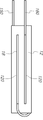
BRIEF DESCRIPTION OF THE DRAWINGS FIG. 1 is an external perspective view showing a basic structure of a chemical water generating unit to which the technique of the present invention is applied. FIG.
2 is an exploded perspective view of a chemical water generating unit to which the technique of the present invention is applied.
3 is a longitudinal sectional view of a chemical water generating unit to which the technique of the present invention is applied.
4 is a plan view of a chemical water generating unit to which the technique of the present invention is applied.
5 is an exploded perspective view of a cavity plate of a chemical water power generating unit to which the technique of the present invention is applied.
DETAILED DESCRIPTION OF THE PREFERRED EMBODIMENTS Hereinafter, preferred embodiments of the present invention will be described in detail with reference to the accompanying drawings.
2 is an exploded perspective view of the water power generating unit, Fig. 3 is a longitudinal sectional view of the water power generating unit, Fig. 4 is a plan view of the water power generating unit, Fig. And Fig. 5 is an exploded perspective view of the air gap plate of the water power generation unit.
1 to 3, the chemical water generating unit of the present invention includes a body 10, a
The main body 10 includes a
In this embodiment, the
In the embodiment of the chemical water generating unit of the present invention, the
Each of the two
As shown in FIGS. 4 and 5,
The
In the embodiment of the present invention, in order to separate the inside of the first containing
The
When the chemical water generating unit of the present invention is used, water used as an electrolyte is injected into the
When the
120: Plus plate
130: Bore plate
Claims (1)
The gap plate 130 having two collector plates 132 made of carbon powder and a tetrafluoroethylene solution and a collector mesh 131 of a metal mesh sandwiched between the two polarization plates 132 And a water accommodating space for water interposed therebetween,
Wherein the positive plate (120) and the air gap plate (130) conduct electricity by a chemical reaction in which water is electrolyzed between the positive plate (120) and the air gap plate (130).
Priority Applications (1)
| Application Number | Priority Date | Filing Date | Title |
|---|---|---|---|
| KR1020150122985A KR20170025890A (en) | 2015-08-31 | 2015-08-31 | Chemcal electric generator |
Applications Claiming Priority (1)
| Application Number | Priority Date | Filing Date | Title |
|---|---|---|---|
| KR1020150122985A KR20170025890A (en) | 2015-08-31 | 2015-08-31 | Chemcal electric generator |
Publications (1)
| Publication Number | Publication Date |
|---|---|
| KR20170025890A true KR20170025890A (en) | 2017-03-08 |
Family
ID=58404613
Family Applications (1)
| Application Number | Title | Priority Date | Filing Date |
|---|---|---|---|
| KR1020150122985A KR20170025890A (en) | 2015-08-31 | 2015-08-31 | Chemcal electric generator |
Country Status (1)
| Country | Link |
|---|---|
| KR (1) | KR20170025890A (en) |
Citations (3)
| Publication number | Priority date | Publication date | Assignee | Title |
|---|---|---|---|---|
| KR200424173Y1 (en) | 2006-06-01 | 2006-08-18 | (주) 코멕스라텍스 | Rubber gloves and dipping mold |
| KR100770049B1 (en) | 2006-03-29 | 2007-10-26 | 권윤석 | Manufacturing process of non slipping rubber gloves |
| KR100833537B1 (en) | 2007-02-14 | 2008-05-29 | 전영식 | A rubber glover |
-
2015
- 2015-08-31 KR KR1020150122985A patent/KR20170025890A/en not_active Application Discontinuation
Patent Citations (3)
| Publication number | Priority date | Publication date | Assignee | Title |
|---|---|---|---|---|
| KR100770049B1 (en) | 2006-03-29 | 2007-10-26 | 권윤석 | Manufacturing process of non slipping rubber gloves |
| KR200424173Y1 (en) | 2006-06-01 | 2006-08-18 | (주) 코멕스라텍스 | Rubber gloves and dipping mold |
| KR100833537B1 (en) | 2007-02-14 | 2008-05-29 | 전영식 | A rubber glover |
Similar Documents
| Publication | Publication Date | Title |
|---|---|---|
| JP5143089B2 (en) | Organic battery that can be used after absorbing moisture | |
| EP1861888A4 (en) | Structure of layering unit cells for high power lithium polymer battery | |
| CN103618096A (en) | Portable water battery element and water battery device comprising the same | |
| CN105591167A (en) | Energy-gathered indication battery | |
| TW201715779A (en) | Non-stationary seawater battery | |
| US10095188B2 (en) | Liquid powered watch | |
| KR20170025890A (en) | Chemcal electric generator | |
| JP5893637B2 (en) | Hydrogen-oxygen gas generator | |
| JP3152190U (en) | Immersion type power generator | |
| US10379499B2 (en) | Liquid powered device | |
| KR100980468B1 (en) | Fuel cell educational kit | |
| JP5986002B2 (en) | Air magnesium battery | |
| CN202905871U (en) | Hydroenergy battery | |
| US20110059354A1 (en) | Pressurized low voltage battery | |
| WO2010056799A3 (en) | Electrolytic hydrogen generating system | |
| CN211789125U (en) | A cylinder lithium cell group for instrument | |
| KR20150139260A (en) | Metal-air fuel cell | |
| CN213425037U (en) | Lithium battery suitable for round battery compartment | |
| JP3109505U (en) | Micro-electric power supply battery | |
| CN206098549U (en) | Water injection type emergency battery | |
| CN209880706U (en) | Waterproof battery | |
| US10754301B2 (en) | Liquid powered device | |
| RU2056676C1 (en) | Gas electric accumulator | |
| CN208939019U (en) | A kind of modified li battery shell | |
| CN203932154U (en) | A kind of casing of lithium ion battery capable of being combined |
Legal Events
| Date | Code | Title | Description |
|---|---|---|---|
| A201 | Request for examination | ||
| E902 | Notification of reason for refusal | ||
| E601 | Decision to refuse application |