KR20170025224A - Grease automatic injection device - Google Patents

Grease automatic injection device Download PDF

Info

Publication number
KR20170025224A
KR20170025224A KR1020150121379A KR20150121379A KR20170025224A KR 20170025224 A KR20170025224 A KR 20170025224A KR 1020150121379 A KR1020150121379 A KR 1020150121379A KR 20150121379 A KR20150121379 A KR 20150121379A KR 20170025224 A KR20170025224 A KR 20170025224A
Authority
KR
South Korea
Prior art keywords
grease
poppet
piston
chamber
compression chamber
Prior art date
Legal status (The legal status is an assumption and is not a legal conclusion. Google has not performed a legal analysis and makes no representation as to the accuracy of the status listed.)
Abandoned
Application number
KR1020150121379A
Other languages
Korean (ko)
Inventor
김성구
Original Assignee
세진 윤활시스템(주)
Priority date (The priority date is an assumption and is not a legal conclusion. Google has not performed a legal analysis and makes no representation as to the accuracy of the date listed.)
Filing date
Publication date
Application filed by 세진 윤활시스템(주) filed Critical 세진 윤활시스템(주)
Priority to KR1020150121379A priority Critical patent/KR20170025224A/en
Publication of KR20170025224A publication Critical patent/KR20170025224A/en
Abandoned legal-status Critical Current

Links

Images

Classifications

    • FMECHANICAL ENGINEERING; LIGHTING; HEATING; WEAPONS; BLASTING
    • F16ENGINEERING ELEMENTS AND UNITS; GENERAL MEASURES FOR PRODUCING AND MAINTAINING EFFECTIVE FUNCTIONING OF MACHINES OR INSTALLATIONS; THERMAL INSULATION IN GENERAL
    • F16NLUBRICATING
    • F16N11/00Arrangements for supplying grease from a stationary reservoir or the equivalent in or on the machine or member to be lubricated; Grease cups
    • FMECHANICAL ENGINEERING; LIGHTING; HEATING; WEAPONS; BLASTING
    • F16ENGINEERING ELEMENTS AND UNITS; GENERAL MEASURES FOR PRODUCING AND MAINTAINING EFFECTIVE FUNCTIONING OF MACHINES OR INSTALLATIONS; THERMAL INSULATION IN GENERAL
    • F16NLUBRICATING
    • F16N11/00Arrangements for supplying grease from a stationary reservoir or the equivalent in or on the machine or member to be lubricated; Grease cups
    • F16N11/10Arrangements for supplying grease from a stationary reservoir or the equivalent in or on the machine or member to be lubricated; Grease cups by pressure of another fluid
    • FMECHANICAL ENGINEERING; LIGHTING; HEATING; WEAPONS; BLASTING
    • F16ENGINEERING ELEMENTS AND UNITS; GENERAL MEASURES FOR PRODUCING AND MAINTAINING EFFECTIVE FUNCTIONING OF MACHINES OR INSTALLATIONS; THERMAL INSULATION IN GENERAL
    • F16NLUBRICATING
    • F16N13/00Lubricating-pumps
    • F16N13/02Lubricating-pumps with reciprocating piston
    • F16N13/06Actuation of lubricating-pumps

Landscapes

  • Engineering & Computer Science (AREA)
  • General Engineering & Computer Science (AREA)
  • Mechanical Engineering (AREA)
  • Reciprocating Pumps (AREA)

Abstract

The present invention provides a grease automatic injection device, which can pump grease without a remaining amount in a grease container, has excellent pumping efficiency, and considers safety when being treated. According to a desirable embodiment of the present invention, the grease automatic injection device comprises: a grease container support plate; an injector column; a vertical transfer rod; an attachment rod; a piston housing; a camshaft; a driving motor; a piston; a screw casing; and a grease pumping screw.

Description

구리스 자동 주입장치{Grease automatic injection device}Grease automatic injection device

본 발명은 구리스 통에 담아져 있는 구리스를 직접 펌핑하여 요구되는 윤활부분에 주입시키기 위한 구리스 자동 주입장치에 관한 것으로, 특히 구리스 통 내부에 잔량 없는 펌핑이 가능하고, 펌핑 효율이 우수하며, 취급시 안전을 고려한 구리스 자동 주입장치에 관한 것이다.The present invention relates to a grease automatic injecting apparatus for directly pumping a grease contained in a grease tank into a required lubricating portion, and more particularly, to a grease automatic injecting apparatus capable of pumping without residual capacity in a grease tank, And an automatic grease automatic injecting apparatus considering safety.

일반적으로 구리스는 중장비 및 대형차량, 산업기계의 마찰 부분등에 주입되면서 장치의 마모 및 원할한 작동을 도모하는데 사용하는 고점성 윤활유이다. 이같이 구리스는 고점성으로 반고체상태이므로 구리스 통에 저장된 구리스를 외부로 자동 주입하기 위해서는 강제적인 펌핑장치가 적용되며, 특히 강제적인 펌핑이 이루어지더라도 잔량이 생길 수 있고, 펌핑장치측에 구리스가 끈끈하게 달라붙어 취급이 용이치 못하므로 이에 대한 대안이 절실하다.In general, grease is a high-viscosity lubricant used in heavy equipment, large vehicles, and friction parts of industrial machinery to assist wear and proper operation of the equipment. Since the grease is semi-solid due to its high viscosity, a forced pumping device is applied to automatically inject the grease stored in the grease container into the outside. In particular, even if the forced pumping is performed, the remaining amount may be generated. On the pumping device side, There is an urgent need for an alternative because it is not easy to handle.

한편, 본 발명의 배경이 되는 기술로는 한국 등록실용 등록번호 제20-0380118호로서, '자동 구리스 주입장치'가 제안되어 있다. 이는 구동모터와 연결된 링크의 구동에 의해 외통속에 삽입된 작동봉은 상하로 승강되면서 구리스를 공간부에 충전시킴과 아울러 공간부에 충전된 구리스는 압축 슬라이더와 밀폐 슬라이더의 작용에 의해 압축되면서 샤프트에 결합된 토출 캡을 통하여 구리스를 외부로 안전하게 배출시킬 수 있는 특징을 갖는다. 따라서 작업자가 필요시마다 짧은 시간에 간단하면서 공구없이 수시로 구리스를 주입할 수 있는 장점을 갖는다. On the other hand, as a technology to be a background of the present invention, Korean Registered Utility Registration No. 20-0380118, 'automatic grease injection device' has been proposed. This is because the operating rod inserted into the outer cylinder is lifted up and down by driving the link connected to the driving motor to fill the space with the grease and the grease filled in the space is compressed by the action of the compression slider and the sealing slider, So that the grease can be safely discharged to the outside through the discharge cap. Therefore, the operator has the advantage of being able to inject grease at any time in a short time, simply and without tools.

그러나 상기 배경기술은 구리스의 점도가 높은 관계로 다사용하게 되더라도 구리스 통에 잔량이 생기므로 경제성이 떨어진다. 또한 외통과 연결부재의 주변으로 구리스가 끈끈하게 달라붙어 취급이 용이치 못한 단점을 가진다.However, the above background art has a high viscosity of the grease, and even if it is used in a large amount, the remaining amount in the grease tank causes economical efficiency. Also, since the grease sticks to the periphery of the outer tube and the connecting member, it has a disadvantage that handling is inconvenient.

한국 등록실용 등록번호 제20-0380118호(자동 구리스 주입장치)Korean Registration No. 20-0380118 (automatic grease injection device)

본 발명은 상기와 같은 사정을 감안하여 창안된 것으로, 구리스 통 내부에 잔량 없는 펌핑이 가능하고, 펌핑 효율이 우수하며, 취급시 안전을 고려한 구리스 자동 주입장치를 제공함에 있다.SUMMARY OF THE INVENTION The present invention has been made in view of the above circumstances, and it is an object of the present invention to provide an automatic pouring apparatus for a green pouring apparatus capable of pumping without remaining in a pouring tank, having excellent pumping efficiency and considering safety during handling.

본 발명의 바람직한 실시예에 따른 구리스 자동 주입장치는,According to a preferred embodiment of the present invention,

구리스 통에 충전되어 있는 구리스를 펌핑하여 필요한 곳에 주입시키기 위한 구리스 자동 주입장치에 있어서,A grease automatic injecting apparatus for pumping a grease filled in a grease tank and injecting it into a required place,

구리스 통을 받쳐주는 구리스 통 받침판과;A grease nipple support plate supporting the grease nipple;

상기 구리스 받침판의 상면 일측에 위치되어 상방으로 일정 높이만큼 입설되어 있고 중공형 단면을 갖는 주입기 컬럼과;An injector column disposed at one side of an upper surface of the supporter and having a hollow section and having a predetermined height upward;

상기 주입기 컬럼의 전면에 위치되어 상하로 일정 구간 이동가능하게 지지되어 있는 수직이송대와;A vertical transfer belt positioned at a front surface of the injector column and supported so as to be movable up and down in a predetermined section;

상기 수직이송대의 상부측에 고정되어 수평 배치되어 있는 구동모터 취부대과;A driving motor mounting base fixed to the upper side of the vertical transfer frame and disposed horizontally;

하면에 수직 하방으로 형성된 구리스 흡입포트, 구리스 흡입포트에 직교 방향으로 연통되어 있는 피스톤 작동실, 피스톤 작동실의 말단에서 연통되어 확장되어 있는 구리스 압축실, 구리스 압축실에 수직 상방으로 연통된 구리스 배출포트를 갖고 상기 구동모터 취부대의 하면에 밀착되게 설치된 피스톤 하우징과;A piston operating chamber communicated in a direction orthogonal to the grease suction port, a grease compression chamber extending and communicating with the end of the piston operating chamber, and a grease communicating vertically upwardly with the grease compression chamber A piston housing having a port and provided so as to be in close contact with a lower surface of the driving motor mounting base;

상기 피스톤 하우징의 중앙에 수직 방향으로 배치되어 회전가능하게 지지되어 상기 있는 캠축과;A camshaft rotatably supported at a center of the piston housing in a vertical direction;

상기 구동모터 취부대에 장착되어 상기 캠축을 회전 구동시키는 구동모터와;A driving motor mounted on the driving motor mounting base for rotationally driving the camshaft;

상기 피스톤 작동실에 미끄럼이동가능하게 삽입되어 상기 캠축의 매 회전마다 피스톤 하우징의 반경 방향에서 진퇴운동하면서 구리스 흡입포트에 구리스 흡입력을 구리스 압축실에는 구리스 압축력을 발생시키는 피스톤과;A piston which is slidably inserted into the piston operating chamber and moves forward and backward in the radial direction of the piston housing every time the camshaft rotates to generate a grease compressive force in the grease compression chamber and a grease compressive force in the grease suction port;

상기 구리스 통보다 작은 직경과 낮은 높이를 갖고 상기 피스톤 하우징의 하면에 장착되어 있는 원통형의 스크류 케이싱과;A cylindrical screw casing having a smaller diameter and a lower height than the grease tank and mounted on a lower surface of the piston housing;

상기 스크류 케이싱의 내부에 배치되고, 동시에 캠축의 하단에 연결되어 구동모터의 회전시 구리스 통내의 구리스를 상방으로 펌핑시키는 구리스 펌핑 스크류;를 포함하여 구성된 것을 특징으로 한다.And a grease pumping screw disposed inside the screw casing and connected to a lower end of the camshaft to pump upward the grease in the grease chamber when the driving motor rotates.

또한, 상기 구리스 압축실에 나사 결합되어 피스톤 하우징에 고정된 압축실 캡과;A compression chamber cap screwed to the grease compression chamber and fixed to the piston housing;

상기 피스톤 작동실의 출구를 개폐 제어하는 포핏과;A poppet for opening and closing an outlet of the piston operating chamber;

상기 압축실 캡과 포핏과의 사이에 끼움 결합되어 피스톤의 구리스 가압 배출시 수축하고 피스톤의 후퇴시 탄성 복원력으로 포핏을 상기 피스톤 작동실의 출구측에 밀어붙이는 고무재의 포핏 시트를 더 포함한 것을 특징으로 한다.And a poppet sheet of rubber material which is fitted between the compression chamber cap and the poppet so as to shrink when the piston is pressurized and discharged by the piston and pushes the poppet to the outlet side of the piston operation chamber by elastic restoring force when the piston is retracted. do.

또한, 포핏은 원추면을 갖는 포핏 몸체와, 포핏 시트에 결합되기 위한 포핏 결합용 보스를 갖는 것을 특징으로 한다.Further, the poppet has a poppet body having a conical surface and a poppet coupling boss for coupling to the poppet sheet.

또한, 포핏 시트는 압출실 캡에 결합되기 위한 시트 결합홈과, 포핏에 결합되기 위한 포핏 결합홈, 구리스 압축실에 접하는 원형 후크부가 형성되어 있는 것을 특징으로 한다.Further, the poppet sheet is characterized in that a seat engagement groove for engagement with the pushing chamber cap, a poppet engagement groove for engagement with the poppet, and a circular hook portion abutting against the grease compression chamber are formed.

또한, 포핏과 포핏 시트간에는 포핏 시트를 1차 압축시킬 수 있는 제1공극을 갖는 것을 특징으로 한다.Further, between the poppet and the poppet sheet, a first gap capable of primarily compressing the poppet sheet is provided.

또한, 압축실 캡과 포핏 시트간에는 포핏 시트를 2차 압축시킬 수 있는 제2공극을 갖는 것을 특징으로 한다.Between the compression chamber cap and the poppet sheet, a second gap capable of secondarily compressing the poppet sheet is provided.

또한, 상기 주입기 컬럼에는 구리스 통내 구리스가 모두 소모된 후 교체를 위해 수직이송대를 상승시키는 수직이송대 승강핸들이 더 구비되어 있는 것을 특징으로 한다.Further, the injector column is further provided with a vertically movable lifting and lowering handle for lifting the vertical lifting belt for replacement after all the grease in the tank is consumed.

또한, 상기 수직이송대 승강핸들은 주입기 컬럼의 상부에 회전가능하게 지지된 피니언 기어축의 일단에 고정되어 있고, 피니언 기어축에 결합된 피니언 기어는 수직이송대에 수직방향으로 연결되어 있는 랙 기어에 이물림 결합되어 있는 것을 특징으로 한다.In addition, the vertical take-off gear lift handle is fixed to one end of a pinion gear shaft rotatably supported on the upper portion of the injector column, and the pinion gear coupled to the pinion gear shaft is vertically connected to the rack in a vertical direction And are engaged with each other.

또한, 일단이 구리스통 받침판측에 연결되고 타단이 상기 수직 이송대에 연결되어 있는 수직이송대 급하강방지용 쇼바가 더 설치되어 있는 것을 특징으로 한다.And a vertically movable lowering preventing shovel, one end of which is connected to the side of the grease bar receiving plate, and the other end of which is connected to the vertical transporting belt, is further provided.

또한, 상기 스크류 케이싱의 하단부에는 구리스 통의 내면에 밀착되는 스크레이퍼가 더 구비되어 있는 것을 특징으로 한다.In addition, a scraper which is in close contact with the inner surface of the grease chamber is further provided at the lower end of the screw casing.

본 발명의 구리스 자동 주입장치에 따르면, 피스톤과 연동하는 구리스 펌핑스크류가 스크류 케이싱 내에 설치되어 강제적으로 구리스를 흡입측에 압송하므로 고점성 그리스의 펌핑성능이 향상된다. 또한, 피스톤 하우징측 구리스 압축실에는 포핏과 포핏시트가 설치되어 흡입력(부압)이 높아지고, 배출력이 향상되어 펌핑 효율이 좋아진다. 또한, 스크레이퍼를 통해 구리스 통의 내면을 훑터 내리고, 구리스 펌핑스크류가 구리스 통의 바닥까지 내려가기 때문에 잔량이 남지 않는다. 또한, 피스톤 하우징은 스크류 케이싱의 외부 최상부에 위치하기 때문에 구리스에 접촉될 염려가 없어 취급이 용이해진다. 또한, 구리스 통을 교체하기 위해 수직이송대의 상승 중 부주의로 급하강이 이루어지더라도 수직이송대 급하강 방지용 쇼바에 의해 급하강이 방지되어 안전사고를 예방할 수 있다.According to the automatic grease inserting apparatus of the present invention, a grease pumping screw interlocking with the piston is installed in the screw casing, and the grease is forcibly fed to the suction side, thereby improving the pumping performance of the high viscosity grease. In addition, a poppet and a poppet seat are provided in the compression chamber of the piston housing side to increase the suction force (negative pressure) and improve the pumping output, thereby improving the pumping efficiency. Also, the inner surface of the grease trough is slid down through the scraper, and the grease pumping screw descends to the bottom of the grease tin, so that no remaining amount remains. Further, since the piston housing is located at the outer uppermost portion of the screw casing, there is no possibility of contact with the grease, thereby facilitating handling. In addition, even if the vertical barrel is inadvertently lowered due to the elevation of the barrel to replace the barrel, it is possible to prevent a safety accident by preventing the barrel bar from being vertically lowered by the lower barrel.

본 명세서에서 첨부되는 다음의 도면들은 본 발명의 바람직한 실시 예를 예시하는 것이며, 발명의 상세한 설명과 함께 본 발명의 기술사상을 더욱 이해시키는 역할을 하는 것이므로, 본 발명은 첨부한 도면에 기재된 사항에만 한정되어서 해석되어서는 아니 된다.
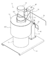
도 1은 본 발명에 따른 구리스 자동 주입장치의 사용상태를 나타낸 사시도.
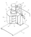
도 2는 도 1에서 구리스 통을 제거한 상태에서의 부분 절취된 사시도.
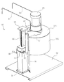
도 3은 도 2의 구리스 자동 주입장치를 배면측에서 본 사시도.
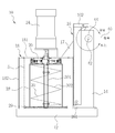
도 4, 도 5 및 도 6은 본 발명에 따른 구리스 자동 주입장치의 사용상태에 따른 순서대로 도시한 작동상태도.
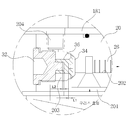
도 7은 도 5의 피스톤 하우징 부분의 확대도.
도 8a 및 도 8b는 도 7에서 구리스 흡입 및 배출시의 작동상태도.
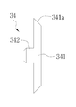
도 9a는 본 발명에 적용되는 포핏의 정단면도.
도 9b는 본 발명에 적용되는 포핏 시트의 정단면도.
BRIEF DESCRIPTION OF THE DRAWINGS The accompanying drawings, which are incorporated in and constitute a part of the specification, illustrate exemplary embodiments of the invention and, together with the description, serve to explain the principles of the invention, Shall not be construed as limiting.
1 is a perspective view illustrating a state of use of an automatic grease injection apparatus according to the present invention;
FIG. 2 is a partially cut away perspective view showing the state in which the cup is removed in FIG. 1; FIG.
FIG. 3 is a perspective view of the automatic automatic irrigation device of FIG. 2 as viewed from the rear side.
FIGS. 4, 5, and 6 are operation states of the automatic inserting apparatus according to the present invention in order, according to the use state.
Figure 7 is an enlarged view of the piston housing portion of Figure 5;
8A and 8B are operational states at the time of suction and discharge of the grease in Fig.
9A is a front sectional view of a poppet according to the present invention.
9B is a front sectional view of the poppet sheet applied to the present invention.

아래에서 본 발명은 첨부된 도면에 제시된 실시 예를 참조하여 상세하게 설명이 되지만 제시된 실시 예는 본 발명의 명확한 이해를 위한 예시적인 것으로 본 발명은 이에 제한되지 않는다. DETAILED DESCRIPTION OF THE PREFERRED EMBODIMENTS The present invention will be described in detail below with reference to the embodiments shown in the accompanying drawings, but the present invention is not limited thereto.

본 발명에 따른 구리스 자동 주입장치(10)는 구리스 통(5)에 충전되어 있는 구리스를 잔량 없이 펌핑하여 주입 비용을 절감할 수 있고, 구리스 펌핑 스크류(30)에 의해 펌핑 효율이 뛰어나고, 피스톤 하우징(20)이 상부측에 설치되어 있어도 펌핑이 이루어짐과 동시에 구리스에 접촉될 염려가 없어 취급이 좋은 이점을 갖는다. 또한 펌핑될 구리스가 구리스 통(5)에 모두 소진된 후 수직이송대(16)를 상승시키는 도중에 수직이송대 승강핸들(40)을 실수로 놓치게 되더라도 급하강을 방지하여 안전한 작업 환경을 갖게 되는 장점을 갖는다.The automatic grease injector 10 according to the present invention can reduce the injection cost by pumping the grease filled in the grease reservoir 5 without remainder and is excellent in the pumping efficiency by the grease pumping screw 30, There is no fear that the pump 20 is brought into contact with the grease while the pump 20 is provided on the upper side, which is advantageous in handling. In addition, even if the vertically slidable lifting handle 40 is accidentally missed while the vertically movable table 16 is lifted after the grease to be pumped is exhausted to the grease container 5, Respectively.

도 1 내지 도 4와 같이 구리스 자동 주입장치(10)는 구리스 통(5)을 받쳐주는 구리스 통 받침판(12)이 구비된다. 구리스 통 받침판(12)은 구리스 통(5)의 밑면보다 큰 지지면을 가지면 족하므로 특정한 형상이나 구조에 한정되는 것은 아니다. 본 실시 예에서는 예시되지 않았지만 구리스 통 받침판(12)에 구리스 통(5)을 지정된 위치에 고정시키는 수단이 더 구비될 수 있다.1 to 4, the automatic grease inserting apparatus 10 is provided with a grease nail support plate 12 for supporting a grease nail 5. Since the grease container support plate 12 has a larger support surface than the bottom surface of the grease container 5, it is not limited to a specific shape or structure. Although not illustrated in this embodiment, it is further possible to provide means for fixing the grease container 5 to the specified position in the grease nail plate 12.

구리스 받침판(12)의 상면 일측에 주입기 컬럼(14)이 입설되어 있다. 주입기 컬럼(14)은 상방으로 일정 높이를 가지고 있고 중공형 단면을 갖는다. 본 실시 예에서 주입기 컬럼(14)은 사각 박스형태로 제작되어 있고 하단에 플랜지가 구비되어 볼트로 구리스 받침판(12)에 고정되어 있다.An injector column 14 is disposed on one side of the top surface of the grease receiving plate 12. The injector column 14 has a constant height upward and has a hollow cross section. In this embodiment, the injector column 14 is manufactured in the form of a square box, and a flange is provided at the lower end thereof, and is fixed to the porous support plate 12 with bolts.

주입기 컬럼(14)에 수직이송대(16)가 설치되어 있다. 수직이송대(16)는 주입기 컬럼(14)의 전면에 위치되어 상하로 일정 구간 이동가능하게 지지되어 있다. 수직이송대(16)는 하단부에 회전가능한 회전롤러(161)가 설치되어 주입기 컬럼(14)의 전면에 지지되어 있고 상단부에 랙기어 연결판(162)이 구비되어 있다. 랙기어 연결판(162)은 후술할 랙 기어(46)의 상단과 연결된다. 따라서 랙 기어(46)의 승강 이동에 연동하여 수직이송대(16)는 컬럼(14)에 회전롤러(161)의 구름운동을 통해 상,하로 이동 안내된다.A vertical transfer belt 16 is provided in the injector column 14. The vertical transfer table 16 is positioned on the front surface of the injector column 14 and is supported so as to be movable up and down in a predetermined section. The vertical transfer table 16 is provided with a rotary roller 161 rotatable at a lower end thereof and is supported on the front surface of the injector column 14 and has a rack gear connecting plate 162 at an upper end thereof. The rack gear connection plate 162 is connected to the upper end of the rack gear 46 to be described later. The vertical transfer belt 16 is guided to move up and down through the rolling motion of the rotary roller 161 to the column 14 in conjunction with the vertical movement of the rack gear 46. [

수직이송대(16)에는 구동모터 취부대(18)이 설치되어 있다. 구동모터 취부대(18)는 수직이송대(16)에 접합된 연결판(17)을 매개로 고정되어 있다. 구동모터 취부대(18)는 수평배치된 원형의 모터 취부판(181)과, 모터 취부판(181)의 하부로 구리스 통(5)을 수용할 수 있는 외통(182)을 더 갖을 수 있다.The vertical transfer table 16 is provided with a drive motor mounting base 18. The drive motor mounting base 18 is fixed via a connecting plate 17 which is vertically connected to the carriage 16. The driving motor mounting base 18 may further include a circular motor mounting plate 181 disposed horizontally and an outer cylinder 182 capable of receiving the grease container 5 below the motor mounting plate 181. [

구동모터 취부대(18)에는 피스톤 하우징(20)이 장착되어 있다. 피스톤 하우징(20)은 구동모터 취부대(18)의 모터 취부판(181) 하면측에 설치된다.A piston housing (20) is mounted on the drive motor mounting base (18). The piston housing 20 is provided on the lower side of the motor mounting plate 181 of the drive motor mounting base 18.

도 7 내지 도 8과 같이 피스톤 하우징(20)은 하면에 수직 하방으로 형성된 구리스 흡입포트(201), 구리스 흡입포트(201)에 직교 방향으로 연통되어 있는 피스톤 작동실(202), 피스톤 작동실(202)의 말단에서 연통되어 확장되어 있는 구리스 압축실(203), 구리스 압축실(203)에 수직 상방으로 연통된 구리스 배출포트(204)를 갖는다. 본 실시 예에서 구리스 흡입포트(201), 피스톤 작동실(202), 구리스 배출포트(204)는 각기 피스톤 하우징(20)의 중심을 기준으로 대칭되어 한 쌍으로 구성된다.As shown in FIGS. 7 to 8, the piston housing 20 is provided with a grease suction port 201 formed vertically downward on the lower surface thereof, a piston operating chamber 202 communicating with the grease suction port 201 in a direction orthogonal to the piston operating chamber 202, 202 and a grease discharge port 204 vertically upwardly communicated with the grease compression chamber 203. The grease discharge port 204 communicates with the grease discharge port 204 at the end thereof. In this embodiment, each of the grease suction port 201, the piston operating chamber 202, and the grease discharge port 204 is symmetrically formed with respect to the center of the piston housing 20 as a pair.

피스톤 하우징(20)의 중앙에 캠축(22)이 회전 가능하게 지지되어 있다. 캠축(22)은 수직 방향으로 배치되어 있다. 캠축(22)은 회전 중심에서 일정 거리(S)를 두고 편심된 캠(221)을 가지고 있다. 캠(221)에는 후술할 피스톤(26)을 연결시키기 위한 피스톤 커넥터(23)가 회전 자유롭게 삽입되어 있다.A camshaft (22) is rotatably supported at the center of the piston housing (20). The camshafts 22 are arranged in the vertical direction. The camshaft 22 has a cam 221 which is eccentric with a certain distance S from the rotation center. A piston connector 23 for connecting a piston 26, which will be described later, is rotatably inserted into the cam 221.

구동모터 취부대(18)에는 캠축(22)을 회전 구동시키는 구동모터(24)가 탑재되어 있다. 구동모터(24)는 감속기가 포함된 기어드 모터가 될 수 있다.A driving motor 24 for rotating the camshaft 22 is mounted on the driving motor mounting base 18. The drive motor 24 may be a geared motor including a speed reducer.

피스톤 하우징(20)에 한 쌍의 피스톤(26)이 설치되어 있다. 피스톤(26)은 피스톤 작동실(202)에 미끄럼이동가능하게 삽입되어 있다. 피스톤(26)은 캠축(22)의 매 회전마다 피스톤 하우징(20)의 반경 방향에서 진퇴운동하면서 구리스 흡입포트(201)에 구리스 흡입력을 구리스 압축실(203)에는 구리스 압축력을 발생시킨다.A pair of pistons (26) are provided in the piston housing (20). The piston 26 is slidably inserted into the piston operating chamber 202. The piston 26 moves forward and backward in the radial direction of the piston housing 20 every time the camshaft 22 rotates to generate a grease suction force in the grease suction port 201 and a grease compressive force in the grease compression chamber 203.

상기 피스톤 하우징(20)의 하면에 스크류 케이싱(28)이 장착되어 있다. 스크류 케이싱(28)은 원통형으로 구리스 통(5)보다 작은 직경과 낮은 높이를 갖는다. 스크류 케이싱(28)의 하단부에는 구리스 통(5)의 내면에 밀착되는 스크레이퍼(29)가 더 구비될 수 있다.A screw casing (28) is mounted on the lower surface of the piston housing (20). The screw casing 28 is cylindrical and has a smaller diameter and a lower height than the grease reservoir 5. A scraper 29 may be further provided on the lower end of the screw casing 28 so as to be in close contact with the inner surface of the cap 5.

스크류 케이싱(28)의 내부에 펌핑 스크류(30)가 배치되어 있다. 펌핑 스크류(30)는 캠축(22)의 하단에 연결되어 구동모터(24)의 회전시 구리스 통(5)내의 구리스를 상방으로 펌핑시킨다. 펌핑 스크류(30)는 스크류 축(301), 스크류 축(301)에 수회 감아져 있는 나선형 날개(302)를 갖는다.A pumping screw (30) is disposed inside the screw casing (28). The pumping screw 30 is connected to the lower end of the camshaft 22 to pump the grease in the grease chamber 5 upward when the drive motor 24 rotates. The pumping screw 30 has a screw shaft 301 and a helical wing 302 wound around the screw shaft 301 several times.

한편, 본 발명은 피스톤(26)의 작동 방향에 따라 구리스의 흡입과 압축이 원활히 이루어지도록 구리스 압축실(203)에 압축실 캡(32), 포핏(34), 포핏 시트(36)가 설치된다.The compression chamber cap 32, the poppet 34, and the poppet seat 36 are provided in the grease compression chamber 203 so that the suction and compression of the grease can be performed smoothly according to the operating direction of the piston 26 .

압축실 캡(32)은 구리스 압축실(203)에 나사 결합되어 피스톤 하우징(20)에 고정되어 있고, 포핏(34)은 피스톤 작동실(202)의 출구측에 위치하여 그 출구를 개폐 제어하고, 포핏 시트(36)는 압축실 캡(32)과 포핏(34)과의 사이에 끼움 결합되어 피스톤(26)의 구리스 가압 배출시 수축하고 피스톤(26)의 후퇴시 탄성 복원력으로 포핏(34)을 피스톤 작동실(202)의 출구측에 밀어붙인다. 포핏 시트(36)는 압축과 탄성 반발력을 가지는 고무재로 제작되어 있다.The compression chamber cap 32 is screwed to the grease compression chamber 203 and fixed to the piston housing 20. The poppet 34 is located at the outlet side of the piston operation chamber 202 to control opening and closing of the outlet The poppet seat 36 is fitted between the compression chamber cap 32 and the poppet 34 to be contracted when the piston 26 is pressurized and discharged from the piston 26 and the resilient restoring force when the piston 26 is retracted, To the outlet side of the piston operating chamber (202). The poppet sheet 36 is made of a rubber material having compression and elastic repulsive force.

포핏(34)은 원추면(341a)을 갖는 포핏 몸체(341)와, 포핏 시트(36)에 결합되기 위한 포핏 결합용 보스(342)를 갖는다. 포핏 시트(36)는 압출실 캡(32)에 결합되기 위한 시트 결합홈(361)과, 포핏(34)에 결합되기 위한 포핏 결합홈(362), 구리스 압축실(203)에 접하는 원형 후크부(363)가 형성되어 있다.The poppet 34 has a poppet body 341 having a conical surface 341a and a poppet coupling boss 342 for engaging the poppet sheet 36. The poppet body 341 has a conical surface 341a. The poppet seat 36 has a seat engagement groove 361 to be engaged with the pushing chamber cap 32, a poppet engagement groove 362 to be engaged with the poppet 34, a circular hook portion (Not shown).

이때 포핏(34)과 포핏 시트(36)간에는 포핏 시트(36)를 1차 압축시킬 수 있는 제1공극(L1)을 갖는다. 또한 압축실 캡(32)과 포핏 시트(36)간에는 포핏 시트(36)를 2차 압축시킬 수 있는 제2공극(L1)을 갖는다.At this time, between the poppet 34 and the poppet seat 36, the first cavity L1 capable of primarily compressing the poppet sheet 36 is provided. Between the compression chamber cap 32 and the poppet seat 36, the second cavity L1 capable of secondarily compressing the poppet seat 36 is provided.

한편, 도 3 및 도 4와 같이 주입기 컬럼(14)에는 구리스 통(5)내 구리스가 모두 소모된 후 교체를 위해 수직이송대(16)를 상승시키는 수직이송대 승강핸들(40)이 더 구비된다.3 and 4, there is further provided a vertically movable lifting / lowering handle 40 for lifting the vertical lifting table 16 for replacement after all the grease in the cup 5 has been consumed. do.

수직이송대 승강핸들(40)은 주입기 컬럼(14)의 상부에 회전가능하게 지지된 피니언 기어축(42)의 일단에 고정되어 있고, 피니언 기어축(42)에 결합된 피니언 기어(44)는 수직이송대(16)에 수직방향으로 연결되어 있는 랙 기어(46)에 이물림 결합되어 있다.The vertically movable lifting handle 40 is fixed to one end of a pinion gear shaft 42 rotatably supported on the upper portion of the injector column 14 and the pinion gear 44 coupled to the pinion gear shaft 42 And is coupled to a rack gear 46 vertically connected to the feeding table 16 in a vertical direction.

또한 본 발명은 구리스 통 받침판(12)측에 연결되고 타단이 상기 수직 이송대(16)에 연결되어 있는 수직이송대 급하강방지용 쇼바(50)가 더 설치될 수 있다. 수직이송대 급하강방지용 쇼바(50)는 내부에 오리피스가 갖는 유체의 저항을 통해 급하강을 제어하는 구조를 갖는다.Further, the present invention may further include a vertically movable lowering preventing shovel 50 connected to the side of the grease nail receiving plate 12 and the other end connected to the vertical conveying belt 16. The vertically movable shovel (50) for preventing the fall of the feed bar has a structure for controlling rapid descent through the resistance of the fluid contained in the orifice.

이와 같이 구성된 구리스 자동 주입장치의 작용을 설명한다.The operation of the automatic grease injector thus constructed will be described.

먼저, 도 4와 같이 수직이송대 승강핸들(40)을 사용하여 수직이송대(16)를 상방으로 위치시킨 상태에서, 구리스통 받침판(12)의 상면에 구리스통(5)을 올려놓는다. 이때 구리스통(5)의 덮개는 제거된 상태이다.4, the vertical barrel lift handle 40 is used to place the vertical barrel 16 in the upper position, and the glass barrel 5 is placed on the upper surface of the grease bar support plate 12. [ At this time, the cover of the grease container 5 is removed.

그 다음, 수직이송대 승강핸들(40)을 자유상태로 한 후 구동모터(24)를 구동시키면 캠축(22)이 연동하여 구리스 펌핑스크류(30)가 회전하고, 동시에 캠(221)에 피스톤 커넥터(23)를 통해 연결된 피스톤(26)이 피스톤 하우징(20)내에서 왕복 동작을 하게 된다.Then, when the drive motor 24 is driven after the vertically movable lifting handle 40 is in the free state, the cam shaft 22 is interlocked to rotate the grease pumping screw 30, and at the same time, The piston 26 connected to the piston housing 20 is reciprocated in the piston housing 20.

이에 의해 구리스통(5)내의 구리스는 도 5와 같이 구리스 펌핑스크류(30)에 의해 스크류 케이싱(28)의 상방으로 펌핑이 이루어지고, 도 8과 같이 피스톤 하우징(20)의 구리스 흡입포트(201)에는 흡입력(부압)이 생성되고 구리스 압축실(203)에는 압축력(구리스 배출력)이 발생된다.As a result, the grease in the grease chamber 5 is pumped upwardly of the screw casing 28 by the grease pumping screw 30 as shown in Fig. 5, and the grease suction port 201 of the piston housing 20 A suction force (negative pressure) is generated and a compressive force (grease-fold output) is generated in the grease compression chamber 203.

피스톤(26)의 흡입 동작시 포핏시트(36)는 탄성 복원력으로 포핏(34)을 원위치시켜 구리스 압축실(203)의 입구를 막고, 피스톤(26)의 압축 동작시 포핏시트(36)는 탄성압축되면서 포핏(34)이 구리스 압축실(203)의 입구를 열게 된다.The poppet seat 36 restores the poppet 34 by restoring the elasticity of the piston 26 during the suction operation of the piston 26 and closes the inlet of the grease compression chamber 203. When the piston 26 is compressed, And the poppet 34 opens the inlet of the grease compression chamber 203 while being compressed.

따라서 스크류 케이싱(28)으로 올라온 구리스는 피스톤(26)의 흡입 동작시 구리스 흡입포트(201)에서 흡입되어지고, 피스톤(26)의 압축 동작시 포핏(34)을 밀고 구리스 압축실(203)을 경유하여 구리스 배출포트(204)를 통해 배출관(19)으로 배출된다.Therefore, the grease that has been introduced into the screw casing 28 is sucked from the grease suction port 201 during the suction operation of the piston 26 and pushes the poppet 34 during the compression operation of the piston 26, And then discharged to the discharge pipe 19 through the grease discharge port 204. [

이같이 구리스의 펌핑이 이루어지는 동안 스크류 케이싱(28)은 하강하고, 이때 스크레이퍼(29)는 구리스 통(5) 내면을 ?고 내려가므로 피스톤 하우징(20)의 둘레로 구리스가 끈끈하게 부착되는 일은 없다.During the pumping of the grease, the screw casing 28 is lowered. At this time, since the scraper 29 is lowered from the inner surface of the grease chamber 5, the grease is not sticky around the piston housing 20.

또한, 구리스 펌핑스크류(30)는 나선형 날개(302)를 이용하여 구리스 통(5)내부의 바닥까지 구리스를 긁어 올리므로 잔량이 남지 않는 경제적 이점을 제공하게 된다.Further, the grease pumping screw 30 scrapes the grease to the bottom of the inside of the grease container 5 by using the spiral blade 302, thereby providing an economical advantage that no remaining amount is left.

이와 같이 하여 구리스의 펌핌이 완료되면, 구리스 통(5)의 교체를 위해 수직이동대 승강핸들(40)을 조작하여 다시 스크류 케이싱(28)을 상방으로 상승시켜 놓는다.When the pumping of the grease is completed in this manner, the screw base 28 is vertically moved upward by operating the vertical lift handle 40 to replace the grease container 5.

이때 부주의로 수직이동대 승강핸들(40)을 놓치게 되더라도, 수직이송대 급하강 방지용 쇼바(50)가 수직이송대(16)의 급하강을 방지하여 안전사고를 예방할 수 있다.Even if the vertical lift handle 40 is inadvertently missed at this time, the vertically movable shovel 50 prevents the vertically movable table 16 from descending, thereby preventing a safety accident.

지금까지 본 발명은 제시된 실시 예를 참조하여 상세하게 설명이 되었지만 이 분야에서 통상의 지식을 가진 자는 제시된 실시 예를 참조하여 본 발명의 기술적 사상을 벗어나지 않는 범위에서 다양한 변형 및 수정 발명을 만들 수 있을 것이다. 본 발명은 이와 같은 변형 및 수정 발명에 의하여 제한되지 않으며 다만 아래에 첨부된 청구범위에 의하여 제한된다. While the present invention has been particularly shown and described with reference to exemplary embodiments thereof, it is evident that many alternatives, modifications and variations will be apparent to those skilled in the art in light of the above teachings. will be. The invention is not limited by these variations and modifications, but is limited only by the claims appended hereto.

12: 구리스통 받침판
14: 주입기 컬럼
16: 수직이송대
18: 구동모터 취부판
20: 피스톤 하우징
22: 캠축
24: 구동모터
26: 피스톤
28: 스크류 케이싱
29: 스크레이퍼
30: 구리스 펌핑 스크류
32: 압축실 캡
34: 포핏
36: 포핏 시트
40: 수직이송대 승강핸들
46: 랙기어
50: 수직이송대 급하강 방지용 쇼바
12: Grease nail plate
14: Injector column
16: Vertical barrow
18: drive motor mounting plate
20: piston housing
22: cam shaft
24: Driving motor
26: Piston
28: Screw casing
29: Scraper
30: Grease pumping screw
32: compression chamber cap
34: Poppet
36: Poppet sheet
40: vertical lifting and lowering handle
46: Racks
50: Shoba for vertical descent prevention

Claims (10)

구리스 통(5)에 충전되어 있는 구리스를 펌핑하여 필요한 곳에 주입시키기 위한 구리스 자동 주입장치에 있어서,
구리스 통(5)을 받쳐주는 구리스 통 받침판(12)과;
상기 구리스 받침판(12)의 상면 일측에 위치되어 상방으로 일정 높이만큼 입설되어 있고 중공형 단면을 갖는 주입기 컬럼(14)과;
상기 주입기 컬럼(14)의 전면에 위치되어 상하로 일정 구간 이동가능하게 지지되어 있는 수직이송대(16)와;
상기 수직이송대(16)의 상부측에 고정되어 수평 배치되어 있는 구동모터 취부대(18)과;
하면에 수직 하방으로 형성된 구리스 흡입포트(201), 구리스 흡입포트(201)에 직교 방향으로 연통되어 있는 피스톤 작동실(202), 피스톤 작동실(202)의 말단에서 연통되어 확장되어 있는 구리스 압축실(203), 구리스 압축실(203)에 수직 상방으로 연통된 구리스 배출포트(204)를 갖고 상기 구동모터 취부대(18)의 하면에 밀착되게 설치된 피스톤 하우징(20)과;
상기 피스톤 하우징(20)의 중앙에 수직 방향으로 배치되어 회전가능하게 지지되어 상기 있는 캠축(22)과;
상기 구동모터 취부대(18)에 장착되어 상기 캠축(22)을 회전 구동시키는 구동모터(24)와;
상기 피스톤 작동실(202)에 미끄럼이동가능하게 삽입되어 상기 캠축(22)의 매 회전마다 피스톤 하우징(20)의 반경 방향에서 진퇴운동하면서 구리스 흡입포트(201)에 구리스 흡입력을 구리스 압축실(203)에는 구리스 압축력을 발생시키는 피스톤(26)과;
상기 구리스 통(5)보다 작은 직경과 낮은 높이를 갖고 상기 피스톤 하우징(20)의 하면에 장착되어 있는 원통형의 스크류 케이싱(28)과;
상기 스크류 케이싱(28)의 내부에 배치되고, 동시에 캠축(22)의 하단에 연결되어 구동모터(24)의 회전시 구리스 통(5)내의 구리스를 상방으로 펌핑시키는 구리스 펌핑 스크류(30);를 포함하여 구성된 것을 특징으로 하는 구리스 자동 주입장치.
1. An automatic grease inserting apparatus for pumping a grease filled in a grease tank (5)
A grease nipple supporting plate (12) for supporting the grease nipple (5);
An injector column (14) located at one side of the upper surface of the supporter plate (12) and extending upwardly to a predetermined height and having a hollow cross section;
A vertical transfer belt 16 positioned on the front surface of the injector column 14 and supported for vertical movement;
A drive motor mounting base 18 fixed horizontally on the upper side of the vertical transfer table 16;
A piston operating chamber 202 communicating in a direction orthogonal to the grease suction port 201, a grease discharge port 201 communicating with the piston compression chamber 202, (203), a piston housing (20) having a grease discharge port (204) vertically upwardly communicated with the grease compaction chamber (203) and closely fitted to a lower surface of the drive motor mounting base (18);
A camshaft 22 rotatably supported at a center of the piston housing 20 in a vertical direction;
A driving motor (24) mounted on the driving motor mounting base (18) for rotationally driving the camshaft (22);
The piston is moved in the radial direction of the piston housing 20 every time the camshaft 22 rotates so that the grease suction force is applied to the grease suction port 201 through the grease compression chamber 203 A piston 26 for generating a grease compressive force;
A cylindrical screw casing 28 having a diameter smaller than that of the grease chamber 5 and mounted on a lower surface of the piston housing 20;
A grease pumping screw 30 disposed inside the screw casing 28 and connected to the lower end of the camshaft 22 to pump upward the grease in the grease chamber 5 when the drive motor 24 rotates; Wherein said automatic injection device comprises:
제 1항에 있어서,
상기 구리스 압축실(203)에 나사 결합되어 피스톤 하우징(20)에 고정된 압축실 캡(32)과;
상기 피스톤 작동실(202)의 출구를 개폐 제어하는 포핏(34)과;
상기 압축실 캡(32)과 포핏(34)과의 사이에 끼움 결합되어 피스톤(26)의 구리스 가압 배출시 수축하고 피스톤(26)의 후퇴시 탄성 복원력으로 포핏(34)을 상기 피스톤 작동실(202)의 출구측에 밀어붙이는 고무재의 포핏 시트(36)를 더 포함한 것을 특징으로 하는 구리스 자동 주입장치.
The method according to claim 1,
A compression chamber cap (32) screwed to the grease compression chamber (203) and fixed to the piston housing (20);
A poppet 34 for opening and closing the outlet of the piston operating chamber 202;
The piston 26 is inserted between the compression chamber cap 32 and the poppet 34 to be contracted when the piston 26 is pressurized with the grease gas and the piston 26 is retracted by the resilient restoring force of the piston 26, Further comprising a poppet sheet (36) of a rubber material which is pushed against the outlet side of the main body (202).
제 2항에 있어서,
포핏(34)은,
원추면(341a)을 갖는 포핏 몸체(341)와, 포핏 시트(36)에 결합되기 위한 포핏 결합용 보스(342)를 갖는 것을 특징으로 하는 구리스 자동 주입장치.
3. The method of claim 2,
The poppet (34)
A poppet body (341) having a conical surface (341a) and a poppet coupling boss (342) to be coupled to the poppet seat (36).
제 2항에 있어서,
포핏 시트(36)는,
압출실 캡(32)에 결합되기 위한 시트 결합홈(361)과, 포핏(34)에 결합되기 위한 포핏 결합홈(362), 구리스 압축실(203)에 접하는 원형 후크부(363)가 형성되어 있는 것을 특징으로 하는 구리스 자동 주입장치.
3. The method of claim 2,
The poppet sheet (36)
A seat coupling groove 361 to be coupled to the pushing chamber cap 32 and a poppet coupling groove 362 to be coupled to the poppet 34 and a circular hook portion 363 to be in contact with the grease compression chamber 203 are formed Wherein the automatic injection device comprises:
제 3항 또는 제 4항에 있어서,
포핏(34)과 포핏 시트(36)간에는 포핏 시트(36)를 1차 압축시킬 수 있는 제1공극(L1)을 갖는 것을 특징으로 하는 구리스 자동 주입장치.
The method according to claim 3 or 4,
Characterized in that a first gap (L1) capable of primarily compressing the poppet seat (36) is provided between the poppet (34) and the poppet seat (36).
제 3항 또는 제 4항에 있어서,
압축실 캡(32)과 포핏 시트(36)간에는 포핏 시트(36)를 2차 압축시킬 수 있는 제2공극(L1)을 갖는 것을 특징으로 하는 구리스 자동 주입장치.
The method according to claim 3 or 4,
Characterized in that a second gap (L1) capable of secondarily compressing the poppet seat (36) is provided between the compression chamber cap (32) and the poppet seat (36).
제 1항에 있어서,
상기 주입기 컬럼(14)에는 구리스 통(5)내 구리스가 모두 소모된 후 교체를 위해 수직이송대(16)를 상승시키는 수직이송대 승강핸들(40)이 더 구비되어 있는 것을 특징으로 하는 구리스 자동 주입장치.
The method according to claim 1,
Characterized in that the injector column (14) further comprises a vertical transfer table lift handle (40) for lifting the vertical transfer table (16) for replacement after all the grease has been consumed in the grease container (5) Injection device.
제 7항에 있어서,
상기 수직이송대 승강핸들(40)은 주입기 컬럼(14)의 상부에 회전가능하게 지지된 피니언 기어축(42)의 일단에 고정되어 있고, 피니언 기어축(42)에 결합된 피니언 기어(44)는 수직이송대(16)에 수직방향으로 연결되어 있는 랙 기어(46)에 이물림 결합되어 있는 것을 특징으로 하는 구리스 자동 주입장치.
8. The method of claim 7,
The vertically movable lifting and lowering handle 40 is fixed to one end of a pinion gear shaft 42 rotatably supported on an upper portion of the injector column 14 and a pinion gear 44 coupled to the pinion gear shaft 42, Is engaged with a rack gear (46) connected in a vertical direction to the vertical transfer table (16).
제 1항에 있어서,
일단이 구리스통 받침판(12)측에 연결되고 타단이 상기 수직 이송대(16)에 연결되어 있는 수직이송대 급하강방지용 쇼바(50)가 더 설치되어 있는 것을 특징으로 하는 구리스 자동 주입장치.
The method according to claim 1,
Further comprising a vertically movable lowering shock absorber (50) having one end connected to the side of the grease cylinder supporter (12) and the other end connected to the vertical transfer belt (16).
제 1항에 있어서,
상기 스크류 케이싱(28)의 하단부에는 구리스 통(5)의 내면에 밀착되는 스크레이퍼(29)가 더 구비되어 있는 것을 특징으로 하는 구리스 자동 주입장치.
The method according to claim 1,
And a scraper (29) attached to the inner surface of the grease chamber (5) at a lower end of the screw casing (28).
KR1020150121379A 2015-08-28 2015-08-28 Grease automatic injection device Abandoned KR20170025224A (en)

Priority Applications (1)

Application Number Priority Date Filing Date Title
KR1020150121379A KR20170025224A (en) 2015-08-28 2015-08-28 Grease automatic injection device

Applications Claiming Priority (1)

Application Number Priority Date Filing Date Title
KR1020150121379A KR20170025224A (en) 2015-08-28 2015-08-28 Grease automatic injection device

Publications (1)

Publication Number Publication Date
KR20170025224A true KR20170025224A (en) 2017-03-08

Family

ID=58403639

Family Applications (1)

Application Number Title Priority Date Filing Date
KR1020150121379A Abandoned KR20170025224A (en) 2015-08-28 2015-08-28 Grease automatic injection device

Country Status (1)

Country Link
KR (1) KR20170025224A (en)

Cited By (3)

* Cited by examiner, † Cited by third party
Publication number Priority date Publication date Assignee Title
KR102044459B1 (en) 2018-11-02 2019-12-02 이일재 Apparatus for feeding grease
KR102408772B1 (en) 2021-11-04 2022-06-13 이일재 Injecting Apparatus of Lubricant
CN117006395A (en) * 2023-07-24 2023-11-07 华能湖南岳阳发电有限责任公司 Grease pump lifting device

Citations (1)

* Cited by examiner, † Cited by third party
Publication number Priority date Publication date Assignee Title
KR200380118Y1 (en) 2004-10-25 2005-03-25 홍국선 automatic ail an inlet pipe aquipment

Patent Citations (1)

* Cited by examiner, † Cited by third party
Publication number Priority date Publication date Assignee Title
KR200380118Y1 (en) 2004-10-25 2005-03-25 홍국선 automatic ail an inlet pipe aquipment

Cited By (3)

* Cited by examiner, † Cited by third party
Publication number Priority date Publication date Assignee Title
KR102044459B1 (en) 2018-11-02 2019-12-02 이일재 Apparatus for feeding grease
KR102408772B1 (en) 2021-11-04 2022-06-13 이일재 Injecting Apparatus of Lubricant
CN117006395A (en) * 2023-07-24 2023-11-07 华能湖南岳阳发电有限责任公司 Grease pump lifting device

Similar Documents

Publication Publication Date Title
KR101063018B1 (en) Air Pressurized Lubricant Automatic Feeding Device
CN101657638B (en) Pumping device and method of pumping out stored fluid
KR20170025224A (en) Grease automatic injection device
KR100921645B1 (en) Pump discharge method of storage liquid in container and its device
CN213505929U (en) Multi-station filling machine
CN102731225B (en) Emulsion explosive continuous filling and conveying piston pump
KR101485168B1 (en) Lubrication Oil Pump
KR101670608B1 (en) Greasing apparatus using radial multi pistons
CN118358801B (en) Liquid preparation filling machine based on go out liquid detection
KR102122642B1 (en) Pneumatic grease pump
CN116833411B (en) Powder forming hydraulic press
CN105669334A (en) Continuous filling and conveying rotary piston pump for emulsion explosives
CN204114521U (en) Novel lubricating grease filling device and corresponding lift
CN220011383U (en) Automatic stacking mechanism convenient to maintain
KR200380118Y1 (en) automatic ail an inlet pipe aquipment
CN212151588U (en) Pneumatic filling mechanism
CN210702176U (en) Unloading structure and punch press in automation of punch press
CN211303477U (en) Plunger type spraying machine
CN105697965A (en) Grease gun capable of automatically conveying grease downwards by foot stamping
JP5774912B2 (en) Cut nozzle
CN210028001U (en) Environment-friendly dustless dry powder material filling machine
KR102206716B1 (en) silicon ejection apparatus
CN111779963B (en) an automatic lubricating device
CN201145130Y (en) Portable high pressure lubricating device
CN224003523U (en) Sinking barrel self-filling type electric filling assembly adapting to standard grease barrel

Legal Events

Date Code Title Description
A201 Request for examination
PA0109 Patent application

Patent event code: PA01091R01D

Comment text: Patent Application

Patent event date: 20150828

PA0201 Request for examination
E902 Notification of reason for refusal
PE0902 Notice of grounds for rejection

Comment text: Notification of reason for refusal

Patent event date: 20161121

Patent event code: PE09021S01D

E701 Decision to grant or registration of patent right
PE0701 Decision of registration

Patent event code: PE07011S01D

Comment text: Decision to Grant Registration

Patent event date: 20161208

PG1501 Laying open of application
NORF Unpaid initial registration fee
PC1904 Unpaid initial registration fee