KR20170023086A - Methods and systems for intra block copy coding with block vector derivation - Google Patents
Methods and systems for intra block copy coding with block vector derivation Download PDFInfo
- Publication number
- KR20170023086A KR20170023086A KR1020177001468A KR20177001468A KR20170023086A KR 20170023086 A KR20170023086 A KR 20170023086A KR 1020177001468 A KR1020177001468 A KR 1020177001468A KR 20177001468 A KR20177001468 A KR 20177001468A KR 20170023086 A KR20170023086 A KR 20170023086A
- Authority
- KR
- South Korea
- Prior art keywords
- vector
- block
- prediction
- derived
- video
- Prior art date
Links
Images


Classifications
-
- H—ELECTRICITY
- H04—ELECTRIC COMMUNICATION TECHNIQUE
- H04N—PICTORIAL COMMUNICATION, e.g. TELEVISION
- H04N19/00—Methods or arrangements for coding, decoding, compressing or decompressing digital video signals
- H04N19/70—Methods or arrangements for coding, decoding, compressing or decompressing digital video signals characterised by syntax aspects related to video coding, e.g. related to compression standards
-
- H—ELECTRICITY
- H04—ELECTRIC COMMUNICATION TECHNIQUE
- H04N—PICTORIAL COMMUNICATION, e.g. TELEVISION
- H04N19/00—Methods or arrangements for coding, decoding, compressing or decompressing digital video signals
- H04N19/50—Methods or arrangements for coding, decoding, compressing or decompressing digital video signals using predictive coding
- H04N19/503—Methods or arrangements for coding, decoding, compressing or decompressing digital video signals using predictive coding involving temporal prediction
- H04N19/51—Motion estimation or motion compensation
- H04N19/513—Processing of motion vectors
- H04N19/521—Processing of motion vectors for estimating the reliability of the determined motion vectors or motion vector field, e.g. for smoothing the motion vector field or for correcting motion vectors
-
- H—ELECTRICITY
- H04—ELECTRIC COMMUNICATION TECHNIQUE
- H04N—PICTORIAL COMMUNICATION, e.g. TELEVISION
- H04N19/00—Methods or arrangements for coding, decoding, compressing or decompressing digital video signals
- H04N19/10—Methods or arrangements for coding, decoding, compressing or decompressing digital video signals using adaptive coding
- H04N19/134—Methods or arrangements for coding, decoding, compressing or decompressing digital video signals using adaptive coding characterised by the element, parameter or criterion affecting or controlling the adaptive coding
- H04N19/146—Data rate or code amount at the encoder output
- H04N19/147—Data rate or code amount at the encoder output according to rate distortion criteria
-
- H—ELECTRICITY
- H04—ELECTRIC COMMUNICATION TECHNIQUE
- H04N—PICTORIAL COMMUNICATION, e.g. TELEVISION
- H04N19/00—Methods or arrangements for coding, decoding, compressing or decompressing digital video signals
- H04N19/10—Methods or arrangements for coding, decoding, compressing or decompressing digital video signals using adaptive coding
- H04N19/134—Methods or arrangements for coding, decoding, compressing or decompressing digital video signals using adaptive coding characterised by the element, parameter or criterion affecting or controlling the adaptive coding
- H04N19/157—Assigned coding mode, i.e. the coding mode being predefined or preselected to be further used for selection of another element or parameter
-
- H—ELECTRICITY
- H04—ELECTRIC COMMUNICATION TECHNIQUE
- H04N—PICTORIAL COMMUNICATION, e.g. TELEVISION
- H04N19/00—Methods or arrangements for coding, decoding, compressing or decompressing digital video signals
- H04N19/10—Methods or arrangements for coding, decoding, compressing or decompressing digital video signals using adaptive coding
- H04N19/169—Methods or arrangements for coding, decoding, compressing or decompressing digital video signals using adaptive coding characterised by the coding unit, i.e. the structural portion or semantic portion of the video signal being the object or the subject of the adaptive coding
- H04N19/186—Methods or arrangements for coding, decoding, compressing or decompressing digital video signals using adaptive coding characterised by the coding unit, i.e. the structural portion or semantic portion of the video signal being the object or the subject of the adaptive coding the unit being a colour or a chrominance component
-
- H—ELECTRICITY
- H04—ELECTRIC COMMUNICATION TECHNIQUE
- H04N—PICTORIAL COMMUNICATION, e.g. TELEVISION
- H04N19/00—Methods or arrangements for coding, decoding, compressing or decompressing digital video signals
- H04N19/46—Embedding additional information in the video signal during the compression process
- H04N19/463—Embedding additional information in the video signal during the compression process by compressing encoding parameters before transmission
-
- H—ELECTRICITY
- H04—ELECTRIC COMMUNICATION TECHNIQUE
- H04N—PICTORIAL COMMUNICATION, e.g. TELEVISION
- H04N19/00—Methods or arrangements for coding, decoding, compressing or decompressing digital video signals
- H04N19/50—Methods or arrangements for coding, decoding, compressing or decompressing digital video signals using predictive coding
- H04N19/593—Methods or arrangements for coding, decoding, compressing or decompressing digital video signals using predictive coding involving spatial prediction techniques
-
- H—ELECTRICITY
- H04—ELECTRIC COMMUNICATION TECHNIQUE
- H04N—PICTORIAL COMMUNICATION, e.g. TELEVISION
- H04N19/00—Methods or arrangements for coding, decoding, compressing or decompressing digital video signals
- H04N19/90—Methods or arrangements for coding, decoding, compressing or decompressing digital video signals using coding techniques not provided for in groups H04N19/10-H04N19/85, e.g. fractals
- H04N19/94—Vector quantisation
Abstract
도출된 블록 벡터를 인트라 블록 복사 모드의 예측자로서 사용하여 비디오를 인코딩하고 디코딩하기 위한 시스템 및 방법이 설명된다. 예시적인 인코딩 방법에서, 인코더는 입력 비디오 블록의 예측을 위한 적어도 제 1 후보 블록 벡터를 식별하며, 여기서 제 1 후보 블록 벡터는 제 1 후보 블록을 나타낸다. 그 다음, 인코더는 제 1 후보 블록을 인코딩하는데 사용된 제 1 예측 벡터(예를 들어, 블록 벡터 또는 움직임 벡터)를 식별한다. 제 1 후보 블록 벡터 및 제 1 예측 벡터로부터, 인코더는 제 1 후보 블록 벡터 및 제 1 예측 벡터로부터 도출된 예측 벡터를 생성한다. 그 다음, 인코더는 입력 비디오 블록의 예측을 위해 도출된 예측 벡터를 사용하여 비트 스트림에서 비디오 블록을 인코딩한다.A system and method for encoding and decoding video using a derived block vector as a predictor of intra block copy mode is described. In an exemplary encoding method, the encoder identifies at least a first candidate block vector for prediction of an input video block, wherein the first candidate block vector represents a first candidate block. The encoder then identifies the first predictive vector (e.g., a block vector or a motion vector) that was used to encode the first candidate block. From the first candidate block vector and the first prediction vector, the encoder generates a prediction vector derived from the first candidate block vector and the first prediction vector. The encoder then encodes the video block in the bitstream using the predictive vector derived for prediction of the input video block.
Description
관련 출원에 대한 상호 참조Cross-reference to related application
본 출원은 2014년 6월 19일에 출원된 미국 가특허 출원 제62/014,664호의 정식 출원이고, 35 U.S.C. §119(e) 하에 이러한 가특허 출원으로부터의 우선권을 주장한다. 이 출원의 내용은 그 전체가 본 명세서에 참고로 통합된다.This application is a formal application of U.S. Provisional Patent Application No. 62 / 014,664, filed June 19, 2014, Priority under §119 (e) from such patent application is asserted. The contents of which are incorporated herein by reference in their entirety.
지난 20년에 걸쳐, 효율적인 디지털 비디오 통신, 분배 및 소비를 가능하게 하기 위해 다양한 디지털 비디오 압축 기술이 개발되고 표준화되었다. 상업적으로 널리 배포된 표준의 대부분은 H.261, MPEG-1, MPEG-2 H.263, MPEG-4(part-2) 및 H.264/AVC(MPEG-4 part 10 Advance Video Coding)와 같이 ISO/IEC 및 ITU-T에 의해 개발되어 있다. 새로운 고급 비디오 압축 기술의 출현(emergence) 및 성숙(maturity)으로 인해, ITU-T VCEG(Video Coding Experts Group) 및 ISO/IEC MPEG에 의한 공동 개발 하에 새로운 비디오 코딩 표준인 HEVC(High Efficiency Video Coding)가 개발되었다. HEVC(ITU-T H.265/ISO/IEC 23008-2)는 2013년 초에 국제 표준으로 승인되었고, 현재 최첨단 H.264/AVC보다 실질적으로 더 높은 코딩 효율을 달성할 수 있다.Over the past two decades, a variety of digital video compression technologies have been developed and standardized to enable efficient digital video communications, distribution and consumption. Most commercial widely distributed standards include H.261, MPEG-1, MPEG-2 H.263, MPEG-4 (part-2) and H.264 / AVC (MPEG-4
스크린 콘텐츠 공유 애플리케이션은 원격 데스크톱, 비디오 회의 및 모바일 미디어 프레젠테이션 애플리케이션의 확산(proliferation)에 따라 최근에 점점 더 대중화되었다. 양방향 스크린 콘텐츠 공유 시스템은 캡처 장치, 인코더 및 송신기를 포함하는 호스트 서브 시스템과, 수신기, 디코더 및 디스플레이(렌더러(renderer))를 포함하는 클라이언트 서브 시스템을 포함할 수 있다. 스크린 콘텐츠 코딩(screen content coding; SCC)을 위한 산업에서 다양한 애플리케이션 요구 사항이 있다. 자연적(natural) 비디오 콘텐츠와 비교할 때, 스크린 콘텐츠는 종종 스크린 콘텐츠에 자주 나타나는 선명한 곡선과 텍스트 때문에 여러 주요 색상과 강한 에지(strong edge)가 있는 수많은 블록을 포함한다. 기존의 비디오 압축 방법이 스크린 콘텐츠를 인코딩하여 해당 콘텐츠를 수신기 측으로 전송하는데 이용될 수 있지만, 대부분의 기존의 방법은 스크린 콘텐츠의 특성을 수용하지 못하며, 따라서 압축 성능이 낮다. 종래의 비디오 코딩 기술을 이용한 스크린 콘텐츠의 재구성은 종종 심각한 품질 문제로 이어진다. 예를 들어, 곡선과 텍스트가 선명하지 않아 인식하기가 어려울 수 있다. 따라서, 스크린 콘텐츠를 효과적으로 재구성하기 위해 잘 설계된 스크린 콘텐츠 압축 방법이 바람직하다.Screen content sharing applications have become more and more popular recently due to the proliferation of remote desktop, video conferencing and mobile media presentation applications. The interactive screen content sharing system may include a host subsystem including a capture device, an encoder and a transmitter, and a client subsystem including a receiver, a decoder and a display (renderer). There are various application requirements in the industry for screen content coding (SCC). Compared to natural video content, screen content often contains many blocks with many primary colors and strong edges due to the sharp curves and text often appearing in screen content. While existing video compression methods can be used to encode screen content and transmit the content to the receiver side, most existing methods do not accommodate the characteristics of the screen content and therefore have poor compression performance. Reconstruction of screen content using conventional video coding techniques often leads to serious quality problems. For example, curves and text are not clear and can be hard to recognize. Thus, a well-designed screen content compression method is desirable for effectively reconstructing screen content.
일부 예시적인 실시예에서, 입력 비디오 블록을 포함하는 비디오를 인코딩하는 비트 스트림을 생성하기 위한 방법이 제공된다. 인코더는 입력 비디오 블록의 예측을 위한 적어도 제 1 후보 블록 벡터(block vector; BV)를 식별하며, 여기서 제 1 후보 블록 벡터는 제 1 후보 블록을 나타낸다. 그 다음, 인코더는 제 1 후보 블록을 인코딩하는데 사용된 제 1 예측 벡터(예를 들어, 블록 벡터 또는 움직임 벡터(motion vector))를 식별한다. 제 1 후보 블록 벡터 및 제 1 예측 벡터로부터,인코더는 제 1 후보 블록 벡터 및 제 1 예측 벡터로부터 도출된 예측 벡터(예를 들어, 도출된 블록 벡터 또는 도출된 움직임 벡터)를 생성한다. 그 다음, 인코더는 입력 비디오 블록의 예측을 위해 도출된 예측 벡터를 사용하여 비트 스트림에서 비디오 블록을 인코딩한다.In some exemplary embodiments, a method is provided for generating a bitstream that encodes video comprising an input video block. The encoder identifies at least a first candidate block vector (BV) for prediction of the input video block, wherein the first candidate block vector represents a first candidate block. The encoder then identifies the first predictor vector (e.g., a block vector or a motion vector) that was used to encode the first candidate block. From the first candidate block vector and the first predictive vector, the encoder generates a predictive vector (e.g., derived block vector or derived motion vector) derived from the first candidate block vector and the first predictive vector. The encoder then encodes the video block in the bitstream using the predictive vector derived for prediction of the input video block.
일부 실시예에서, 인코더는 비트 스트림에서 도출된 예측 벡터를 시그널링한다. 일부 실시예에서, 인코더는 비트 스트림에서 제 1 예측 벡터를 시그널링하고, 또한 입력 비디오 블록이 제 1 예측 벡터로부터 도출되는 도출된 예측 벡터를 사용하여 인코딩됨을 나타내는 플래그를 비트 스트림에서 시그널링한다.In some embodiments, the encoder signals the prediction vector derived from the bitstream. In some embodiments, the encoder signals the first predictive vector in the bitstream, and also signals in the bitstream a flag indicating that the input video block is encoded using the derived predictive vector derived from the first predictive vector.
일부 실시예에서, 인코더는 병합(merge) 후보 리스트에서 도출된 예측 벡터를 식별하는 인덱스를 비트 스트림에서 시그널링한다.In some embodiments, the encoder signals in the bitstream an index that identifies the predictive vector derived from the merge candidate list.
도출된 예측 벡터는 제 1 후보 블록 벡터 및 제 1 예측 벡터를 부가함으로써 생성될 수 있다. 이러한 실시예에서, 제 1 예측 벡터가 제 2 블록 벡터인 경우, 도출된 예측 벡터는 제 1 후보 블록 벡터 및 제 2 블록 벡터(제 1 예측 벡터)를 부가함으로써 생성된 블록 벡터일 수 있다. 제 1 예측 벡터가 움직임 벡터인 경우, 도출된 예측 벡터는 다음 식에 따라 제 1 후보 블록 벡터 및 제 1 움직임 벡터를 부가함으로써 생성된 움직임 벡터일 수 있다:The derived prediction vector may be generated by adding a first candidate block vector and a first prediction vector. In this embodiment, when the first predictive vector is a second block vector, the derived predictive vector may be a block vector generated by adding a first candidate block vector and a second block vector (first predictive vector). If the first predictive vector is a motion vector, the derived predictive vector may be a motion vector generated by adding a first candidate block vector and a first motion vector according to the following equation:
MVd = BV0 +((MV1 + 2)>>2) MVd = BV0 + ((MV1 + 2) " 2)
여기서 BV0는 제 1 후보 블록 벡터이고, MV1은 제 1 움직임 벡터이며, MVd는 도출된 움직임 벡터이다.Where BV0 is the first candidate block vector, MV1 is the first motion vector, and MVd is the derived motion vector.
일부 예시적인 실시예에서, 도출된 예측 벡터(블록 벡터 또는 움직임 벡터)는 병합 후보로서 사용된다. 예시적인 방법에서, 인코더는 입력 비디오 블록의 인코딩을 위해 적어도 제 1 블록 벡터 병합 후보를 식별하고, 인코더는 제 1 후보 블록을 인코딩하는데 사용된 제 1 예측 벡터를 식별한다. 그 후, 인코더는 제 1 블록 벡터 병합 후보 및 제 1 예측 벡터로부터 도출된 예측 벡터(도출된 블록 벡터 또는 도출된 움직임 벡터)를 생성한다. 도출된 예측 벡터는 병합 후보 리스트에 삽입된다. 병합 후보 리스트로부터, 인코더는 입력 비디오 블록의 예측을 위해 선택된 예측 벡터를 선택한다. 그 후, 인코더는 입력 비디오 블록의 예측을 위해 선택된 예측 벡터를 사용하여 비트 스트림에서 비디오 입력 블록을 인코딩한다. 선택된 예측 벡터는 도출된 예측 벡터일 수 있다.In some exemplary embodiments, the derived predictive vector (block vector or motion vector) is used as a merging candidate. In an exemplary method, the encoder identifies at least a first block vector merging candidate for encoding of the input video block, and the encoder identifies the first prediction vector used to encode the first candidate block. Thereafter, the encoder generates a predictive vector (derived block vector or derived motion vector) derived from the first block vector merging candidate and the first predictive vector. The derived prediction vector is inserted into the merging candidate list. From the merging candidate list, the encoder selects the prediction vector selected for prediction of the input video block. The encoder then encodes the video input block in the bitstream using the prediction vector selected for prediction of the input video block. The selected prediction vector may be the derived prediction vector.
이러한 일부 실시예에서, 인코더는 도출된 예측 벡터를 생성하고 삽입하기 전에 병합 후보 리스트가 가득한(full)지를 결정한다. 병합 후보 리스트에서 도출된 예측 벡터를 생성하고 삽입하는 단계는 병합 후보 리스트가 가득하지 않은 것으로 결정이 이루어진 후에만 수행된다.In some such embodiments, the encoder determines whether the merged candidate list is full before generating and inserting the derived predictive vector. The step of generating and inserting the prediction vector derived from the merging candidate list is performed only after the determination is made that the merging candidate list is not full.
이러한 일부 실시예에서, 인코더는 이전에 인코딩된 비디오 블록의 검색을 수행함으로써 제 1 후보 블록 벡터를 식별한다.In some such embodiments, the encoder identifies the first candidate block vector by performing a search of the previously encoded video block.
비트 스트림으로부터 코딩된 비디오 블록을 디코딩하는 예시적인 방법에서, 디코더는 입력 비디오 블록의 예측을 위한 적어도 제 1 후보 블록 벡터를 식별하며, 여기서 제 1 후보 블록 벡터는 제 1 후보 블록을 나타낸다. 디코더는 제 1 후보 블록을 인코딩하는데 사용된 제 1 예측 벡터를 식별한다. 그 후, 디코더는 제 1 블록 벡터 및 제 1 예측 벡터로부터 도출된 예측 벡터를 생성하고, 코딩된 비디오 블록의 예측을 위해 도출된 예측 벡터를 사용하여 코딩된 비디오 블록을 디코딩한다.In an exemplary method of decoding a coded video block from a bitstream, the decoder identifies at least a first candidate block vector for prediction of the input video block, wherein the first candidate block vector represents a first candidate block. The decoder identifies the first prediction vector used to encode the first candidate block. The decoder then generates a predictive vector derived from the first block vector and the first predictive vector and decodes the coded video block using the predictive vector derived for prediction of the coded video block.
이러한 실시예에서, 제 1 후보 블록 벡터는 다양한 상이한 기술을 이용하여 식별될 수 있다. 이러한 하나의 방법에서, 제 1 후보 블록 벡터는 비트 스트림에서 시그널링되고, 제 1 후보 블록 벡터의 식별은 비트 스트림에서 시그널링된 제 1 후보 블록 벡터를 수신하는 것을 포함한다. 이러한 방법에서, 도출된 예측 벡터의 생성은 입력 비디오 블록이 도출된 예측 벡터로 인코딩된다는 것을 나타내는 플래그를 비트 스트림에서 수신하는 것에 응답하여 수행될 수 있다. 이러한 다른 방법에서, 제 1 후보 블록 벡터의 식별은 제 1 블록 벡터 병합 후보의 식별을 포함한다. 이러한 실시예에서, 도출된 예측 벡터는 또한 병합 후보일 수 있다. 디코더는 도출된 예측 벡터 병합 후보를 식별하는 비트 스트림에서 인덱스를 수신하는 것에 응답하여 코딩된 비디오 블록을 디코딩하기 위해 도출된 예측 벡터를 사용할 수 있다.In such an embodiment, the first candidate block vector may be identified using a variety of different techniques. In one such method, the first candidate block vector is signaled in the bitstream, and the identification of the first candidate block vector comprises receiving a first candidate block vector signaled in the bitstream. In this way, the generation of the derived prediction vector can be performed in response to receiving in the bitstream a flag indicating that the input video block is encoded with the derived prediction vector. In this alternative method, the identification of the first candidate block vector includes the identification of the first block vector merging candidate. In such an embodiment, the derived prediction vector may also be a merge candidate. The decoder may use the derived prediction vector to decode the coded video block in response to receiving the index in the bitstream that identifies the derived predicted vector merging candidate.
아래에서 먼저 간단히 설명되는 첨부된 다이어그램과 함께 예로서 제시된 다음의 설명으로부터 더욱 상세한 이해가 이루어질 수 있다.
도 1은 블록 기반 비디오 인코더의 일례를 예시하는 블록도이다.
도 2는 블록 기반 비디오 디코더의 일례를 예시하는 블록도이다.
도 3은 8개 방향성 예측 모드의 일례의 다이어그램이다.
도 4는 33개의 방향성 예측 모드와 2개의 무방향성 예측 모드의 일례를 예시하는 다이어그램이다.
도 5는 수평 예측의 일례의 다이어그램이다.
도 6은 평면 모드의 일례의 다이어그램이다.
도 7은 움직임 예측의 일례를 예시하는 다이어그램이다.
도 8은 화상 내의 블록 레벨 움직임의 일례를 예시하는 다이어그램이다.
도 9는 코딩된 비트 스트림 구조의 일례를 예시하는 다이어그램이다.
도 10은 예시적인 통신 시스템을 예시하는 다이어그램이다.
도 11은 예시적인 무선 송수신 유닛(wireless transmit/receive unit; WTRU)을 예시하는 다이어그램이다.
도 12는 예시적인 스크린 콘텐츠 공유 시스템을 예시하는 다이어그램이다.
도 13은 풀(full) 프레임 인트라 블록 복사 모드의 일례를 예시하는 다이어그램이다.
도 14는 로컬 영역 인트라 블록 복사 모드의 일례를 예시하는 다이어그램이다.
도 15는 인트라 블록 복사 병합을 위한 공간 후보의 2개의 예를 예시하는 다이어그램이다.
도 16은 예시적인 블록 벡터 도출을 예시하는 다이어그램이다.
도 17은 예시적인 움직임 벡터 도출을 예시하는 다이어그램이다.
도 18a 및 도 18b는 모두 예시적인 방법의 흐름도이다.A more detailed understanding may be obtained from the following description, given by way of example, together with the accompanying diagram, which is briefly described below.
Figure 1 is a block diagram illustrating an example of a block-based video encoder.
2 is a block diagram illustrating an example of a block-based video decoder.
3 is a diagram of an example of eight directional prediction modes.
4 is a diagram illustrating an example of 33 directional prediction modes and two non-directional prediction modes.
5 is a diagram of an example of the horizontal prediction.
6 is a diagram of an example of the planar mode.
7 is a diagram illustrating an example of motion prediction.
8 is a diagram illustrating an example of block level motion in an image.
9 is a diagram illustrating an example of a coded bitstream structure.
10 is a diagram illustrating an exemplary communication system.
11 is a diagram illustrating an exemplary wireless transmit / receive unit (WTRU).
12 is a diagram illustrating an exemplary screen content sharing system.
13 is a diagram illustrating an example of a full frame intra-block copy mode.
14 is a diagram illustrating an example of the local area intra-block copy mode.
15 is a diagram illustrating two examples of spatial candidates for intra block copy merging.
16 is a diagram illustrating an exemplary block vector derivation.
17 is a diagram illustrating an exemplary motion vector derivation.
Figures 18A and 18B are all flow diagrams of an exemplary method.
예시적인 실시예의 상세한 설명이 이제 다양한 도면을 참조하여 제공될 것이다. 이러한 설명이 가능한 구현에 대한 상세한 예를 제공하지만, 제공된 상세 사항은 예로서 의도되고, 적용의 범위를 결코 제한하지 않는다는 것이 주목되어야 한다.A detailed description of exemplary embodiments will now be presented with reference to the various figures. While this description provides detailed examples of possible implementations, it should be noted that the details provided are intended to be examples only and are not intended to limit the scope of application in any way.
도 1은 블록 기반 비디오 인코더, 예를 들어, 하이브리드 비디오 인코딩 시스템의 일례를 예시하는 블록도이다. 비디오 인코더(100)는 입력 비디오 신호(102)를 수신할 수 있다. 입력 비디오 신호(102)는 블록 단위로 처리될 수 있다. 비디오 블록은 임의의 크기의 블록일 수 있다. 예를 들어, 비디오 블록 유닛은 16×16 픽셀을 포함할 수 있다. 16×16 픽셀의 비디오 블록 유닛은 매크로 블록(macroblock; MB)으로 지칭될 수 있다. 고효율 비디오 코딩(High Efficiency Video Coding; HEVC)에서, (예를 들어, 코딩 트리 유닛(coding tree unit; CTU) 또는 코딩 유닛(coding unit; CU)으로 지칭될 수 있고, 이러한 두 용어는 본 개시물을 위해 동등한) 확장된 블록 크기는 고해상도(예를 들어, 1080p 이상) 비디오 신호를 효율적으로 압축하는데 사용될 수 있다. HEVC에서, CU는 최대 64×64 픽셀일 수 있다. CU는 별개의 예측 방법이 적용될 수 있는 예측 유닛(prediction unit; PU)으로 분할될 수 있다.1 is a block diagram illustrating an example of a block-based video encoder, e.g., a hybrid video encoding system. The
입력 비디오 블록(예를 들어, MB 또는 CU)에 대해, 공간적 예측(160) 및/또는 시간적 예측(162)이 수행될 수 있다. 공간적 예측(예를 들어, "인트라 예측")은 현재 비디오 블록을 예측하기 위해 동일한 비디오 화상/슬라이스에서 이미 코딩된 이웃한 블록으로부터의 픽셀을 사용할 수 있다. 공간적 예측은 비디오 신호에 내재하는 공간적 중복성(spatial redundancy)을 감소시킬 수 있다. 시간적 예측(예를 들어, "인터 예측" 또는 "움직임 보상된 예측")은 현재 비디오 블록을 예측하기 위해 (예를 들어, "참조 화상"으로 지칭될 수 있는) 이미 코딩된 비디오 화상으로부터의 픽셀을 사용할 수 있다. 시간적 예측은 비디오 신호에 내재하는 시간적 중복성을 감소시킬 수 있다. 비디오 블록에 대한 시간적 예측 신호는 현재 블록과 참조 화상에서의 예측 블록 사이의 움직임의 양 및/또는 방향을 나타낼 수 있는 하나 이상의 움직임 벡터에 의해 시그널링될 수 있다. (예들 들어, H.264/AVC 및/또는 HEVC에 대한 경우와 같이) 다수의 참조 화상이 지원되면, 비디오 블록에 대해, 이의 참조 화상 인덱스가 전송될 수 있다. 참조 화상 인덱스는 참조 화상 저장부(164)에서의 어떤 참조 화상으로부터 시간적 예측 신호가 발생하는지를 식별하는데 사용될 수 있다.For the input video block (e.g., MB or CU),
인코더 내의 모드 판정 블록(180)은 예를 들어 공간적 및/또는 시간적 예측 후에 예측 모드를 선택할 수 있다. 예측 블록은 116에서 현재 비디오 블록으로부터 감산될 수 있다. 예측 잔차(residual)는 변환(104)되고/되거나 양자화(106)될 수 있다. 양자화된 잔차 계수는 재구성된 잔차를 형성하기 위해 역 양자화(110)되고/되거나 역 변환(112)될 수 있으며, 이는 재구성된 비디오 블록을 형성하기 위해 예측 블록(126)에 다시 부가될 수 있다.The
인루프 필터링(in-loop filtering)(예를 들어, 디블로킹 필터, 샘플 적응 오프셋, 적응 루프 필터 및/또는 등)은 참조 화상 저장부(164)에 배치되고/되거나 차후 비디오 블록을 코딩하는데 사용되기 전에 재구성된 비디오 블록에 적용될 수 있다(166). 비디오 인코더(100)는 출력 비디오 스트림(120)을 출력할 수 있다. 출력 비디오 비트스트림(120)을 형성하기 위해, 코딩 모드(예를 들어, 인터 예측 모드 또는 인트라 예측 모드), 예측 모드 정보, 움직임 정보 및/또는 양자화된 잔차 계수는 비트 스트림을 형성하기 위해 압축 및/또는 패킹(packing)되도록 엔트로피 코딩 유닛(108)에 전송될 수 있다. 참조 화상 저장부(164)는 디코딩된 화상 버퍼(DPB)로서 지칭될 수 있다.In-loop filtering (e.g., deblocking filters, sample adaptive offsets, adaptive loop filters, and / or the like) may be placed in the reference image storage 164 and / (166). ≪ / RTI > The
도 2는 블록 기반 비디오 디코더의 일례를 예시하는 블록도이다. 비디오 디코더(200)는 비디오 비트 스트림(202)을 수신할 수 있다. 비디오 비트 스트림(202)은 엔트로피 디코딩 유닛(208)에서 언패킹(unpacking) 및/또는 엔트로피 디코딩될 수 있다. 비디오 비트 스트림을 인코딩하는데 사용된 코딩 모드 및/또는 예측 정보는 예측 블록을 형성하기 위해 (예를 들어, 인트라 코딩된다면) 공간적 예측 유닛(260) 및/또는 (예를 들어, 인터 코딩된다면) 시간적 예측 유닛(262)에 전송될 수 있다. 인터 코딩된다면, 예측 정보는 예측 블록 크기, (예를 들어, 움직임의 방향 및 양을 나타낼 수 있는) 하나 이상의 움직임 벡터, 및/또는 (예를 들어, 예측 신호를 획득하기 위해 어떤 참조 화상으로부터 나타낼 수 있는) 하나 이상의 참조 인덱스를 포함할 수 있다. 움직임 보상된 예측은 시간적 예측 블록을 형성하기 위해 시간적 예측 유닛(262)에 의해 적용될 수 있다.2 is a block diagram illustrating an example of a block-based video decoder. The
잔차 변환 계수는 잔차 블록을 재구성하기 위해 역 양자화 유닛(210) 및 역변환 유닛(212)에 전송될 수 있다. 예측 블록 및 잔차 블록은 226에서 함께 부가될 수 있다. 재구성된 블록은 참조 화상 저장부(264)에 저장되기 전에 인루프 필터링(266)을 통과할 수 있다. 참조 화상 저장부(264)에서의 재구성된 비디오는 디스플레이 디바이스를 구동하는데 사용되고/되거나 차후 비디오 블록을 예측하는데 사용될 수 있다. 비디오 디코더(200)는 재구성된 비디오 신호(220)를 출력할 수 있다. 참조 화상 저장부(264)는 또한 디코딩된 화상 버퍼(DPB)로서 지칭될 수 있다.The residual transform coefficients may be sent to the
비디오 인코더 및/또는 디코더(예를 들어, 비디오 인코더(100) 또는 비디오 디코더(200))는 (예를 들어, 인트라 예측으로서 지칭될 수 있는) 공간적 예측을 수행할 수 있다. 공간적 예측은 (예를 들어, 방향성 인트라 예측으로서 지칭될 수 있는) 복수의 예측 방향 중 하나를 뒤따르는 이미 코딩된 이웃한 픽셀로부터 예측함으로써 수행될 수 있다.A video encoder and / or decoder (e.g.,
도 3은 8개의 방향성 예측 모드의 일례의 다이어그램이다. 도 3의 8개의 방향성 예측 모드는 H.264/AVC에서 지원될 수 있다. 일반적으로 도 3의 300에 도시된 바와 같이, (DC 모드 2를 포함하는) 9개의 모드는 다음과 같다:3 is a diagram of an example of eight directional prediction modes. The eight directional prediction modes of FIG. 3 may be supported in H.264 / AVC. Generally, as shown in 300 of FIG. 3, nine modes (including DC mode 2) are as follows:
![]()
![]()
![]()
![]()
![]()
![]()
![]()
![]()
![]()
![]()
![]()
![]()
![]()
![]()
![]()
![]()
![]()
![]()
공간적 예측은 다양한 크기 및/또는 형상의 비디오 블록 상에서 수행될 수 있다. 비디오 신호의 휘도 성분(luma component)의 공간적 예측은 예를 들어 (예를 들어, H.264/AVC에서) 4×4, 8×8 및 16×16 픽셀의 블록 크기에 대해 수행될 수 있다. 비디오 신호의 채도 성분(chroma component)의 공간적 예측은 예를 들어 (예를 들어, H.264/AVC에서) 8×8의 블록 크기에 대해 수행될 수 있다. 크기 4×4 또는 8×8의 휘도 블록에 대해, 총 9개의 예측 모드, 예를 들어, (예를 들어, H.264/AVC에서) 8개의 방향성 예측 모드 및 DC 모드가 지원될 수 있다. 4개의 예측 모드는 예를 들어, 16×16 크기의 휘도 블록에 대해 수평, 수직, DC 및 평면 예측 모드가 지원될 수 있다.Spatial prediction can be performed on video blocks of various sizes and / or shapes. Spatial prediction of the luma component of a video signal may be performed for block sizes of 4x4, 8x8, and 16x16 pixels (e.g., in H.264 / AVC), for example. Spatial prediction of a chroma component of a video signal may be performed, for example, for an 8x8 block size (e.g., in H.264 / AVC). For a luminance block of size 4x4 or 8x8, a total of nine prediction modes may be supported, for example eight directional prediction modes and DC modes (e.g., in H.264 / AVC). Four prediction modes can be supported, for example horizontal, vertical, DC and planar prediction modes for 16x16 luminance blocks.
더욱이, 방향성 인트라 예측 모드 및 무방향성 예측 모드가 지원될 수 있다.Furthermore, a directional intra-prediction mode and a non-directional prediction mode can be supported.
도 4는 33개의 방향성 예측 모드 및 2개의 무방향성 예측 모드의 일례를 예시하는 다이어그램이다. 일반적으로 도 4의 400에 도시된 33개의 방향성 예측 모드 및 2개의 무방향성 예측 모드가 HEVC에 의해 지원될 수 있다. 더욱 큰 블록 크기를 사용하는 공간적 예측이 지원될 수 있다. 예를 들어, 공간적 예측은 임의의 크기, 예를 들어 4×4, 8×8, 16×16, 32×32 또는 64×64의 정사각형 블록 크기의 블록 상에서 수행될 수 있다. (예를 들어, HEVC에서) 방향성 인트라 예측은 1/32 픽셀 정밀도로 수행될 수 있다.4 is a diagram illustrating an example of 33 directional prediction modes and two non-directional prediction modes. Generally, the 33 directional prediction modes and the two non-directional prediction modes shown in 400 of FIG. 4 can be supported by the HEVC. Spatial prediction using larger block sizes may be supported. For example, spatial prediction may be performed on blocks of any size, e.g., 4x4, 8x8, 16x16, 32x32 or 64x64 square block sizes. Directional intra prediction can be performed with a precision of 1/32 pixel (for example, at HEVC).
예를 들어, 방향성 인트라 예측에 부가하여, (예를 들어, H.264/AVC, HEVC 등에서) 무방향성 인트라 예측 모드가 지원될 수 있다. 무방향성 인트라 예측 모드는 DC 모드 및/또는 평면 모드를 포함할 수 있다. DC 모드에 대해, 이용 가능한 이웃한 픽셀을 평균함으로써 예측 값이 획득될 수 있고, 예측 값은 전체 블록에 균일하게 적용될 수 있다. 평면 모드에 대해, 선형 보간은 느린 전환(slow transition)으로 평활한 영역(smooth regions)을 예측하는데 이용될 수 있다. H.264/AVC는 16×16 휘도 블록 및 채도 블록에 대한 평면 모드를 사용할 수 있다.For example, in addition to directional intra prediction, a non-directional intra prediction mode (e.g., in H.264 / AVC, HEVC, etc.) may be supported. The non-directional intra prediction mode may include a DC mode and / or a flat mode. For the DC mode, a prediction value can be obtained by averaging the available neighboring pixels, and the prediction value can be uniformly applied to the entire block. For planar mode, linear interpolation can be used to predict smooth regions with slow transitions. H.264 / AVC can use the flat mode for 16 × 16 luminance blocks and saturation blocks.
인코더(예컨대, 인코더(100))는 비디오 블록에 대한 최상의 코딩 모드를 결정하기 위해 (예를 들어, 도 1의 블록(180)에서) 모드 판정을 수행할 수 있다. 인코더가 (예를 들어, 인터 예측 대신에) 인트라 예측을 적용하도록 결정할 때, 인코더는 이용 가능한 모드의 세트로부터 최적의 인트라 예측 모드를 결정할 수 있다. 선택된 방향성 인트라 예측 모드는 입력 비디오 블록 내의 임의의 텍스처, 에지 및/또는 구조의 방향에 대한 강한 암시(hint)를 제공할 수 있다.The encoder (e.g., encoder 100) may perform mode determination (e.g., at
도 5는 일반적으로 도 5에서 500으로 도시된 바와 같은 (예를 들어, 4×4 블록에 대한) 수평 예측의 일례의 다이어그램이다. 이미 재구성된 픽셀 P0, P1, P2 및 P3(즉, 음영 박스)은 현재 4×4 비디오 블록 내의 픽셀을 예측하는데 사용될 수 있다. 수평 예측에서, 재구성된 픽셀, 예를 들어 픽셀 P0, P1, P2 및/또는 P3은 4×4 블록을 예측하기 위해 대응하는 행의 방향을 따라 수평으로 전파될 수 있다. 예를 들어, L(x,y)가 (x,y), x,y = 0...3에서 예측되는 픽셀일 수 있는 아래의 식 (1)에 따라 예측이 수행될 수 있다.5 is a diagram of an example of horizontal prediction (e.g., for a 4x4 block) as shown generally at 500 in FIG. The already reconstructed pixels P0, P1, P2, and P3 (i.e., the shaded boxes) can be used to predict the pixels in the current 4x4 video block. In the horizontal prediction, the reconstructed pixels, for example pixels P0, P1, P2 and / or P3, may propagate horizontally along the direction of the corresponding row to predict the 4x4 block. For example, prediction may be performed according to the following equation (1), which may be a pixel predicted at L (x, y), (x, y), x, y = 0 ... 3.
L(x,0) = P0 L (x, 0) = P0
L(x,1) = P1 (1) L (x, 1) = P1 (1)
L(x,2) = P2 L (x, 2) = P2
L(x,3) = P3 L (x, 3) = P3
도 6은 일반적으로 도 6의 600에 도시된 바와 같은 평면 모드의 일례의 다이어그램이다. 평면 모드는 이에 따라 수행될 수 있다: (T에 의해 표시된) 최상단 행의 가장 오른쪽 픽셀은 가장 오른쪽 열의 픽셀을 예측하기 위해 복제될 수 있다. (L에 의해 표시된) 왼쪽 열의 최하단 픽셀은 최하단 행의 픽셀을 예측하기 위해 복제될 수 있다. (왼쪽 블록에 도시된 바와 같은) 수평 방향의 이중 선형 보간은 중심 픽셀의 제 1 예측 H(x,y)를 생성하기 위해 수행될 수 있다. (예를 들어, 오른쪽 블록에 도시된 바와 같은) 수직 방향의 이중 선형 보간은 중심 픽셀의 제 2 예측 V(x,y)를 생성하기 위해 수행될 수 있다. 수평 예측과 수직 예측 사이의 평균은 L(x,y) = ((H(x,y) + V(x,y))>>l)를 이용하여 최종 예측 L(x,y)를 획득하기 위해 수행될 수 있다.6 is a diagram of an example of a planar mode as generally shown at 600 in FIG. The planar mode can be performed accordingly: The rightmost pixel of the top row (denoted by T) can be replicated to predict the pixels in the rightmost column. The lowermost pixel in the left column (denoted by L) can be replicated to predict the pixels in the bottom row. A bilinear interpolation in the horizontal direction (as shown in the left block) can be performed to generate the first prediction H (x, y) of the center pixel. Vertical bilinear interpolation (e.g., as shown in the right block) may be performed to generate a second prediction V (x, y) of the center pixel. The average between the horizontal prediction and the vertical prediction is obtained by obtaining the final prediction L (x, y) using L (x, y) = ((H (x, y) + V . ≪ / RTI >
도 7 및 도 8은 일반적으로 700 및 800에 도시된 바와 같이 (예를 들어, 도 1의 시간적 예측 유닛(162)을 사용하여) 비디오 블록의 움직임 예측의 일례를 예시하는 다이어그램이다. 화상 내의 블록 레벨 움직임의 일례를 예시하는 도 8은 예를 들어 참조 화상 "Ref pic 0", "Ref pic 1" 및 "Ref pic 2"를 포함하는 예시적인 디코딩된 화상 버퍼를 예시하는 다이어그램이다. 현재 화상의 블록 B0, B1 및 B2는 각각 참조 화상 "Ref pic 0", "Ref pic 1" 및 "Ref pic 2" 내의 블록으로부터 예측될 수 있다. 움직임 예측은 현재 비디오 블록을 예측하기 위해 이웃한 비디오 프레임으로부터의 비디오 블록을 사용할 수 있다. 움직임 예측은 시간적 상관을 활용하고/하거나, 비디오 신호에 내재하는 시간적 중복성을 제거할 수 있다. 예를 들어, H.264/AVC 및 HEVC에서, 시간적 예측은 다양한 크기의 비디오 블록 상에서 수행될 수 있다(예를 들어, 휘도 성분에 대해, 시간적 예측 블록 크기는 H.264/AVC에서는 16×16에서 4×4까지, HEVC에서는 64×64에서 4×4까지 다양할 수 있다). (mvx, mvy)의 움직임 벡터로, 시간적 예측은 다음의 식 (2)에 의해 제공되는 바와 같이 수행될 수 있다:Figures 7 and 8 are diagrams illustrating an example of motion prediction of a video block, generally as shown at 700 and 800 (e.g., using the
P(x,y) = ref(x - mvx, y - mvy) (2) P (x, y) = ref (x - mvx, y - mvy)
여기서 ref(x,y)는 참조 화상의 위치(x,y)에서의 픽셀 값일 수 있고, P(x,y)는 예측된 블록일 수 있다. 비디오 코딩 시스템은 단편적인 픽셀 정밀도(fractional pixel precision)로 인터 예측을 지원할 수 있다. 움직임 벡터(mvx, mvy)가 단편적인 픽셀 값을 가질 때, 단편적인 픽셀 위치에서 픽셀 값을 획득하기 위해 하나 이상의 보간 필터가 적용될 수 있다. 블록 기반 비디오 코딩 시스템은 예를 들어 예측 신호가 상이한 참조 화상으로부터의 다수의 예측 신호를 조합함으로써 형성될 수 있는 시간적 예측을 개선하기 위해 다중 가설 예측을 사용할 수 있다. 예를 들어, H.264/AVC 및/또는 HEVC는 2개의 예측 신호를 조합할 수 있는 양방향 예측을 사용할 수 있다. 양방향 예측은 다음의 식 (3)과 같은 예측을 형성하기 위해 참조 화상으로부터의 각각의 2개의 예측 신호를 조합할 수 있다:Where ref (x, y) may be the pixel value at the location (x, y) of the reference picture and P (x, y) may be the predicted block. Video coding systems can support inter prediction with fractional pixel precision. When the motion vector (mvx, mvy) has a fractional pixel value, one or more interpolation filters may be applied to obtain the pixel value at the fractional pixel location. A block-based video coding system can use multiple hypothesis prediction, for example, to improve the temporal prediction that a prediction signal can be formed by combining multiple prediction signals from different reference pictures. For example, H.264 / AVC and / or HEVC can use bi-directional prediction capable of combining two prediction signals. Bidirectional prediction can combine each of the two prediction signals from the reference picture to form a prediction such as the following equation (3): < EMI ID =

여기서, P0(x,y) 및 P1(x,y)는 각각 제 1 및 제 2 예측 블록일 수 있다. 식 (3)에 예시된 바와 같이, 각각 2개의 움직임 벡터(mvxo, mvyo) 및 (mvx1, mvy1)로 2개의 참조 화상(ref0(x,y)) 및 (ref1(x,y))로부터의 움직임 보상된 예측을 수행함으로써 2개의 예측 블록이 획득될 수 있다. 예측 블록 P(x,y)는 예측 잔차 블록을 형성하기 위해 (예를 들어, 116에서) 소스 비디오 블록으로부터 감산될 수 있다. 예측 잔차 블록은 (예를 들어, 변환 유닛(104)에서) 변환되고/되거나 (예를 들어, 양자화 유닛(106)에서) 양자화될 수 있다. 양자화된 잔차 변환 계수 블록은 비트 레이트를 감소시키기 위해 엔트로피 코딩되도록 엔트로피 코딩 유닛(예컨대, 엔트로피 코딩 유닛(108))에 전송될 수 있다. 엔트로피 코딩된 잔차 계수는 출력 비디오 비트 스트림(예를 들어, 비트 스트림(120))의 일부를 형성하도록 패킹될 수 있다.Here, P 0 (x, y) and P 1 (x, y) may be first and second prediction blocks, respectively. Two reference images ref 0 (x, y) and (ref 1 (x, y)) are generated by two motion vectors (mvx o , mvy o ) and (mvx 1 , mvy 1 ), respectively, , y)) by performing motion compensated prediction from the motion vector (x, y). The prediction block P (x, y) may be subtracted from the source video block (e.g., at 116) to form a prediction residual block. The prediction residual block may be transformed (e.g., in transform unit 104) and / or quantized (e.g., in quantization unit 106). The quantized residual transform coefficient block may be sent to an entropy coding unit (e.g., entropy coding unit 108) to be entropy coded to reduce the bit rate. The entropy coded residual coefficients may be packed to form a portion of the output video bitstream (e.g., bitstream 120).
단층 비디오 인코더는 단일 비디오 시퀀스 입력을 취하고, 단층 디코더에 전송되는 단일 압축된 비트 스트림을 생성할 수 있다. 비디오 코덱은 (예를 들어, 위성, 케이블 및 지상 전송 채널을 통해 TV 신호를 전송하는 것과 같지만, 이에 제한되지 않는) 디지털 비디오 서비스를 위해 설계될 수 있다. 이기종(heterogeneous) 환경에서 배치된 비디오 중심 애플리케이션으로, 다양한 애플리케이션을 가능하게 하도록 비디오 코딩 표준의 확장으로서 다층 비디오 코딩 기술이 개발될 수 있다. 예를 들어, 스케일러블(scalable) 비디오 코딩 및/또는 멀티 뷰(multi-view) 비디오 코딩과 같은 다층 비디오 코딩 기술은 각각의 층이 특정 공간적 해상도, 시간적 해상도, 충실도(fidelity) 및/또는 뷰(view)의 비디오 신호를 재구성하기 위해 디코딩될 수 있는 하나 이상의 비디오 층을 처리하도록 설계될 수 있다. 단층 인코더 및 디코더가 도 1 및 도 2를 참조하여 설명되지만, 본 명세서에 설명된 개념은 예를 들어 멀티 뷰 및/또는 스케일러블 코딩 기술에 대해 다층 인코더 및/또는 디코더를 이용할 수 있다.A single layer video encoder can take a single video sequence input and produce a single compressed bitstream that is sent to a single layer decoder. Video codecs may be designed for digital video services (e.g., but not limited to, transmitting TV signals over satellite, cable, and terrestrial transport channels). With video-centric applications deployed in heterogeneous environments, multilayer video coding techniques can be developed as an extension of video coding standards to enable a variety of applications. For example, multi-layer video coding techniques, such as scalable video coding and / or multi-view video coding, require each layer to have a specific spatial resolution, temporal resolution, fidelity, and / lt; / RTI > may be designed to process one or more video layers that can be decoded to reconstruct the video signal of the view. Although a single layer encoder and decoder are described with reference to Figures 1 and 2, the concepts described herein may utilize multi-layered encoders and / or decoders for multi-view and / or scalable coding techniques, for example.
스케일러블 비디오 코딩은 이기종 네트워크를 통해 상이한 능력을 가진 디바이스 상에서 실행하는 비디오 애플리케이션에 대한 경험의 품질을 향상시킬 수 있다. 스케일러블 비디오 코딩은 최고 표현(예를 들어, 시간적 해상도, 공간적 해상도, 품질 등)에서 신호를 한번 인코딩할 수 있지만, 클라이언트 디바이스 상에서 실행하는 어떤 애플리케이션이 필요로 하는 특정 레이트 및 표현에 따라 비디오 스트림의 서브세트로부터의 디코딩을 가능하게 한다. 스케일러블 비디오 코딩은 넌스케일러블(non-scalable) 솔루션에 비해 대역폭 및/또는 스토리지를 절약할 수 있다. 국제 비디오 표준, 예를 들어 MPEG-2 Video, H.263, MPEG4 Visual, H.264 등은 확장성(scalability)의 모드를 지원하는 도구 및/또는 프로파일을 가질 수 있다.Scalable video coding can improve the quality of experience for video applications running on devices with different capabilities over heterogeneous networks. Scalable video coding can encode a signal once in a top presentation (e.g., temporal resolution, spatial resolution, quality, etc.), but it can also be used to encode a video stream in accordance with the particular rate and presentation required by an application running on the client device. Thereby enabling decoding from the subset. Scalable video coding can save bandwidth and / or storage compared to non-scalable solutions. International video standards, such as MPEG-2 Video, H.263, MPEG4 Visual, H.264, etc., may have tools and / or profiles that support a mode of scalability.
표 1은 이들을 지원할 수 있는 대응하는 표준과 함께 상이한 타입의 확장성의 일례를 제공한다. 비트 깊이 확장성 및/또는 채도 포맷 확장성은 예를 들어 프로페셔널(professional) 비디오 애플리케이션에 의해 주로 사용될 수 있는 비디오 포맷(예를 들어, 8비트 비디오보다 높고, YUV4:2:0보다 높은 채도 샘플링 포맷)에 연결될 수 있다. 종횡비 확장성이 제공될 수 있다.Table 1 provides an example of the different types of extensibility with the corresponding standards that can support them. Bit depth extensibility and / or chroma format extensibility may be used, for example, in a video format (e.g., higher than 8-bit video and higher than YUV4: 2: 0) that can be used primarily by professional video applications Lt; / RTI > Aspect ratio scalability can be provided.
스케일러블 HEVCH.264 / AVC, SVC
Scalable HEVC
YUV4:4:4YUV4: 2: 0? YUV4: 2: 2,
YUV4: 4: 4
스케일러블 비디오 코딩은 기본 계층 비트 스트림을 사용하여 제 1 비디오 파라미터 세트와 연관된 제 1 비디오 품질 레벨을 제공할 수 있다. 스케일러블 비디오 코딩은 하나 이상의 향상 계층(enhancement layer) 비트 스트림을 사용하여 하나 이상의 향상된 파라미터 세트와 연관된 하나 이상의 고품질(higher quality) 레벨을 제공할 수 있다. 비디오 파라미터 세트는 공간적 해상도, 프레임 레이트, (예를 들어, SNR, PSNR, VQM, 시각적 품질 등의 형태의) 재구성된 비디오 품질, (예를 들어, 둘 이상의 뷰를 가진) 3D 능력, 휘도 및 채도 비트 깊이, 채도 포맷 및 기본 단층 코딩 표준 중 하나 이상을 포함할 수 있다. 상이한 사용 케이스는 예를 들어 표 1에 예시된 바와 같이 상이한 타입의 확장성을 사용할 수 있다. 스케일러블 코딩 아키텍처는 하나 이상의 확장성(예를 들어, 표 1에 나열된 확장성)을 지원하도록 구성될 수 있는 공통 구조를 제공할 수 있다. 스케일러블 코딩 아키텍처는 최소 구성 노력으로 상이한 확장성을 지원하기 위해 유연할 수 있다. 코딩 로직(예를 들어, 인코딩 및/또는 디코딩 로직)이 스케일러블 코딩 시스템 내에서 최대로 재사용될 수 있도록 스케일러블 코딩 아키텍처는 블록 레벨 동작으로의 변경을 필요로 하지 않을 수 있는 적어도 하나의 바람직한 동작 모드를 포함할 수 있다. 예를 들어, 화상 레벨 계층간 처리 및 관리 유닛에 기초한 스케일러블 코딩 아키텍처가 제공될 수 있고, 계층간 예측은 화상 레벨에서 수행될 수 있다. Scalable video coding may use a base layer bitstream to provide a first video quality level associated with a first set of video parameters. Scalable video coding may use one or more enhancement layer bitstreams to provide one or more higher quality levels associated with one or more enhanced parameter sets. The video parameter set may include spatial resolution, frame rate, reconstructed video quality (e.g., in the form of SNR, PSNR, VQM, visual quality, etc.), 3D capability (e.g., with two or more views) Bit depth, saturation format, and basic single layer coding standards. Different use cases can use different types of extensibility, for example as illustrated in Table 1. The scalable coding architecture may provide a common structure that may be configured to support one or more extensibility (e.g., the scalability listed in Table 1). Scalable coding architectures can be flexible to support different scalability with minimal configuration effort. The scalable coding architecture may include at least one preferred operation (e. G., ≪ RTI ID = 0.0 > Mode. For example, a scalable coding architecture based on image level inter-layer processing and management units can be provided, and inter-layer prediction can be performed at the image level.
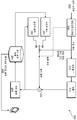
도 9는 코딩된 비트 스트림 구조의 일례를 예시하는 다이어그램이다. 코딩된 비트 스트림(1000)은 다수의 NAL(Network Abstraction layer) 유닛(1001)으로 구성된다. NAL 유닛은 코딩된 슬라이스(1006)와 같은 코딩된 샘플 데이터, 또는 파라미터 세트 데이터, 슬라이스 헤더 데이터(1005) 또는 (SEI 메시지로서 지칭될 수 있는) 보충 강화 정보(supplemental enhancement information) 데이터(1007)와 같은 고레벨의 신택스 메타데이터를 포함할 수 있다. 파라미터 세트는 필수 신택스 요소(syntax element)를 포함하는 고레벨의 신택스 구조이며, 이러한 신택스 구조는 다중 비트 스트림 계층(예를 들어 비디오 파라미터 세트(1002)(VPS))에 적용할 수 있거나, 하나의 계층 내의 코딩된 비디오 시퀀스(예를 들어 시퀀스 파라미터 세트(1003)(SPS))에 적용할 수 있으며, 또는 하나의 코딩된 비디오 시퀀스 내의 다수의 코딩된 화상(예를 들어 화상 파라미터 세트(1004)(PPS))에 적용할 수 있다. 파라미터 세트는 비디오 비트 스트림의 코딩된 화상과 함께 전송되거나, (신뢰 가능한 채널, 하드 코딩 등을 사용한 대역외 전송을 포함하는) 다른 수단을 통해 전송될 수 있다. 슬라이스 헤더(1005)는 또한 어떤 슬라이스 또는 화상 타입에 대해서만 상대적으로 작거나 관련이 있는 몇몇 화상 관련 정보를 포함할 수 있는 고레벨의 신택스 구조이다. SEI 메시지(1007)는 디코딩 프로세스에 의해 필요하지 않을 수 있지만, 화상 출력 타이밍 또는 디스플레이뿐만 아니라 손실 탐지 및 숨김과 같은 다양한 다른 목적을 위해 사용될 수 있는 정보를 반송한다.9 is a diagram illustrating an example of a coded bitstream structure. The coded bitstream 1000 is comprised of a plurality of NAL (Network Abstraction Layer)
도 10은 통신 시스템의 일례를 예시하는 다이어그램이다. 통신 시스템(1300)은 인코더(1302), 통신 네트워크(1304) 및 디코더(1306)를 포함할 수 있다. 인코더(1302)는 유선 접속부 또는 무선 접속부일 수 있는 접속부(1308)를 통해 네트워크(1304)와 통신할 수 있다. 인코더(1302)는 도 1의 블록 기반 비디오 인코더와 유사할 수 있다. 인코더(1302)는 단층 코덱(예를 들어, 도 1) 또는 다층 코덱을 포함할 수 있다. 예를 들어, 인코더(1302)는 화상 레벨 ILP를 지원하는 다층(예를 들어, 2 계층) 스케일러블 코딩 시스템일 수 있다. 디코더(1306)는 유선 접속부 또는 무선 접속부일 수 있는 접속부(1310)를 통해 네트워크(1304)와 통신할 수 있다. 디코더(1306)는 도 2의 블록 기반 비디오 디코더와 유사할 수 있다. 디코더(1306)는 단층 코덱(예를 들어, 도 2) 또는 다층 코덱을 포함할 수 있다. 예를 들어, 디코더(1306)는 화상 레벨 ILP를 지원하는 다층(예를 들어, 2 계층) 스케일러블 디코딩 시스템일 수 있다. 10 is a diagram illustrating an example of a communication system. The
인코더(1302) 및/또는 디코더(1306)는 디지털 텔레비전, 무선 방송 시스템, 네트워크 요소/단말기, (예를 들어, HTTP(Hypertext Transfer Protocol) 서버와 같은) 콘텐츠 또는 웹 서버와 같은 서버, PDA(personal digital assistant), 랩톱 또는 데스크톱 컴퓨터, 태블릿 컴퓨터, 디지털 카메라, 디지털 기록 디바이스, 비디오 게임 디바이스, 비디오 게임 콘솔, 셀룰러 또는 위성 라디오 전화, 디지털 미디어 플레이어 등과 같지만, 이에 한정되지 않는 매우 다양한 유선 통신 디바이스 및/또는 무선 송수신 유닛(wireless transmit/receive unit; WTRU)에 통합될 수 있다.Encoder 1302 and / or decoder 1306 may be a digital television, a wireless broadcast system, a network element / terminal, a server such as a content (such as a Hypertext Transfer Protocol) server or a web server, a personal digital assistant but are not limited to, a variety of wired communication devices and / or devices, such as, but not limited to, digital assistant, laptop or desktop computers, tablet computers, digital cameras, digital recording devices, video game devices, video game consoles, cellular or satellite radio telephones, Or a wireless transmit / receive unit (WTRU).
통신 네트워크(1304)는 적절한 타입의 통신 네트워크일 수 있다. 예를 들어, 통신 네트워크(1304)는 음성, 데이터, 비디오, 메시징, 방송 등과 같은 콘텐츠를 다수의 무선 사용자에게 제공하는 다중 액세스 시스템일 수 있다. 통신 네트워크(1304)는 다수의 무선 사용자가 무선 대역폭을 포함하는 시스템 자원의 공유를 통해 이러한 콘텐츠에 액세스하도록 할 수 있다. 예를 들어, 통신 네트워크(1304)는 CDMA(code division multiple access), TDMA(time division multiple access), FDMA(frequency division multiple access), OFDMA(orthogonal FDMA), SC-FDMA(single-carrier FDMA) 등과 같은 하나 이상의 채널 액세스 방법을 채용할 수 있다. 통신 네트워크(1304)는 다수의 접속된 통신 네트워크를 포함할 수 있다. 통신 네트워크(1304)는 인터넷, 및/또는 셀룰러 네트워크, WiFi 핫스팟, 인터넷 서비스 제공자(Internet Service Provider; ISP) 네트워크 등과 같은 하나 이상의 사설 상용 네트워크를 포함할 수 있다.
도 11은 예시적인 WTRU의 시스템도이다. 도시된 바와 같이, 예시적인 WTRU(1202)는 프로세서(1218), 송수신기(1220), 송수신 요소(1222), 스피커/마이크로폰(1224), 키패드 또는 키보드(1226), 디스플레이/터치 패드(1228), 비이동식 메모리(1230), 이동식 메모리(1232), 전원(1234), GPS(global positioning system) 칩셋(1236) 및/또는 다른 주변 장치(1238)를 포함할 수 있다. WTRU(1202)는 실시예와 일치하면서 상술한 요소의 임의의 서브 조합을 포함할 수 있다는 것이 이해될 것이다. 더욱이, 인코더(예를 들어, 인코더(100)) 및/또는 디코더(예를 들어, 디코더(200))가 통합되는 단말기는 도 11의 WTRU(1202)를 참조하여 본 명세서에 도시되고 설명된 요소의 일부 또는 전부를 포함할 수 있다.11 is a system diagram of an exemplary WTRU. As shown, the
프로세서(1218)는 범용 프로세서, 특수 목적 프로세서, 종래의 프로세서, 디지털 신호 프로세서(digital signal processor; DSP), 그래픽 처리 유닛(graphics processing unit; GPU), 복수의 마이크로 프로세서, DSP 코어와 관련된 하나 이상의 마이크로 프로세서, 제어기, 마이크로 제어기, ASIC(Application Specific Integrated Circuit), FPGA(Field Programmable Gate Array) 회로, 임의의 다른 타입의 집적 회로(integrated circuit; IC), 상태 머신 등일 수 있다. 프로세서(1218)는 신호 코딩, 데이터 처리, 전력 제어, 입출력 처리, 및/또는 WTRU(1500)가 유선 및/또는 무선 환경에서 동작하도록 할 수 있는 임의의 다른 기능을 수행할 수 있다. 프로세서(1218)는 송수신 요소(1222)에 결합될 수 있는 송수신기(1220)에 결합될 수 있다. 도 11은 프로세서(1218) 및 송수신기(1220)를 별개의 구성 요소로서 도시하지만, 프로세서(1218) 및 송수신기(1220)는 전자 패키지 및/또는 칩 내에 함께 통합될 수 있다는 것이 이해될 것이다.The
송수신 요소(1222)는 무선 인터페이스(1215)를 통해 신호를 다른 단말기로 송신하고/하거나 다른 단말로부터 신호를 수신하도록 구성될 수 있다. 예를 들어, 하나 이상의 실시예에서, 송수신 요소(1222)는 RF 신호를 송신하고/하거나 수신하도록 구성된 안테나일 수 있다. 하나 이상의 실시예에서, 송수신 요소(1222)는 예를 들어 IR, UV 또는 가시광 신호를 송신하고/하거나 수신하도록 구성된 이미터/검출기일 수 있다. 하나 이상의 실시예에서, 송수신 요소(1222)는 RF 및 광 신호 둘 다를 송신하고/하거나 수신하도록 구성될 수 있다. 송수신 요소(1222)는 무선 신호의 임의의 조합을 송신하고/하거나 수신하도록 구성될 수 있다는 것이 이해될 것이다.The
게다가, 송수신 요소(1222)가 도 11에서 단일 요소로서 도시되어 있지만, WTRU(1202)는 많은 송수신 요소(1222)를 포함할 수 있다. 특히, WTRU(1202)는 MIMO 기술을 채용할 수 있다. 따라서, 일 실시예에서, WTRU(1202)는 무선 인터페이스(1215)를 통해 무선 신호를 송수신하기 위한 2개 이상의 송수신 요소(1222)(예를 들어, 다중 안테나)를 포함할 수 있다.In addition, although the transmit / receive
송수신기(1220)는 송수신 요소(1222)에 의해 송신될 수 있는 신호를 변조하고/하거나, 송수신 요소(1222)에 의해 수신되는 신호를 복조하도록 구성될 수 있다. 상술한 바와 같이, WTRU(1202)는 다중 모드 능력을 가질 수 있다. 따라서, 송수신기(1220)는 예를 들어 UTRA 및 IEEE 802.11과 같은 다수의 RAT를 통해 WTRU(1500)가 전달할 수 있도록 하기 위한 다수의 송수신기를 포함할 수 있다.The
WTRU(1202)의 프로세서(1218)는 스피커/마이크로폰(1224), 키패드(1226), 및/또는 디스플레이/터치 패드(1228)(예를 들어, LCD(liquid crystal display) 디스플레이 유닛 또는 유기 발광 다이오드(organic light-emitting diode; OLED) 디스플레이 유닛)에 결합될 수 있고, 이로부터 사용자 입력 데이터를 수신할 수 있다. 프로세서(1218)는 또한 사용자 데이터를 스피커/마이크로폰(1224), 키패드(1226) 및/또는 디스플레이/터치 패드(1228)로 출력할 수 있다. 게다가, 프로세서(1218)는 비이동식 메모리(1230) 및/또는 이동식 메모리(1232)와 같은 임의의 타입의 적절한 메모리로부터의 정보에 액세스하고, 데이터를 이러한 메모리 내에 저장할 수 있다. 비이동식 메모리(1230)는 RAM(random-access memory), ROM(read-only memory), 하드 디스크 또는 임의의 다른 타입의 메모리 저장 디바이스를 포함할 수 있다. 이동식 메모리(1232)는 SIM(subscriber identity module) 카드, 메모리 스틱, 보안 디지털(secure digital; SD) 메모리 카드 등을 포함할 수 있다. 하나 이상의 실시예에서, 프로세서(1218)는 서버 또는 가정용 컴퓨터(도시되지 않음)와 같이 WTRU(1202) 상에 물리적으로 위치되지 않는 메모리로부터의 정보에 액세스하고, 데이터를 이러한 메모리에 저장할 수 있다.The
프로세서(1218)는 전원(1234)으로부터 전력을 수신할 수 있고, 전력을 WTRU(1202) 내의 다른 구성 요소에 분배하고/하거나 제어하도록 구성될 수 있다. 전원(1234)은 WTRU(1202)에 전력을 공급하기 위한 임의의 적절한 디바이스일 수 있다. 예를 들어, 전원(1234)은 하나 이상의 건전지(예를 들어, 니켈 카드뮴(NiCd), 니켈 아연(NiZn), 니켈 금속 수소화물(NiMH), 리튬 이온(Li-ion) 등), 태양 전지, 연료 전지 등을 포함할 수 있다.The
프로세서(1218)는 WTRU(1202)의 현재 위치에 관한 위치 정보(예를 들어, 경도 및 위도)를 제공하도록 구성될 수 있는 GPS 칩셋(1236)에 결합될 수 있다. GPS 칩셋(1236)으로부터의 정보에 부가하거나 대신에, WTRU(1202)는 단말기(예를 들어, 기지국)로부터 무선 인터페이스(1215)를 통해 위치 정보를 수신하고/하거나, 둘 이상의 인접 기지국으로부터 수신되는 신호의 타이밍에 기초하여 위치를 결정할 수 있다. WTRU(1202)는 실시예와 일치하면서 임의의 적절한 위치 결정 방법에 의해 위치 정보를 획득할 수 있다.The
프로세서(1218)는 또한, 부가적인 특징, 기능성 및/또는 유선 또는 무선 연결성을 제공하는 하나 이상의 소프트웨어 및/또는 하드웨어 모듈을 포함할 수 있는 다른 주변 장치(1238)에 결합될 수 있다. 예를 들어, 주변 장치(1238)는 가속도계, 방향 센서, 움직임 센서, 근접 센서, 전자 나침반, 위성 송수신기, 디지털 카메라 및/또는 비디오 레코더(예를 들어, 사진 및/또는 비디오용), 범용 직렬 버스(USB) 포트, 진동 디바이스, 텔레비전 송수신기, 핸즈프리 헤드셋, Bluetooth® 모듈, 주파수 변조된(FM) 라디오 유닛, 및 디지털 뮤직 플레이어, 미디어 플레이어, 비디오 게임 플레이어 모듈, 인터넷 브라우저 등과 같은 소프트웨어 모듈을 포함할 수 있다.The
예로서, WTRU(1202)는 무선 신호를 송신하고/하거나 수신하도록 구성될 수 있으며, 사용자 장비(UE), 이동국, 고정 또는 이동 가입자 유닛, 페이저, 셀룰러 전화, 개인 휴대 정보 단말기(PDA), 스마트 폰, 랩톱, 넷북, 태블릿 컴퓨터, 개인용 컴퓨터, 무선 센서, 가전 제품, 또는 압축된 비디오 통신을 수신하고 처리할 수 있는 임의의 다른 단말기를 포함할 수 있다.The
WTRU(1202) 및/또는 통신 네트워크(예를 들어, 통신 네트워크(804))는 WCDMA(wideband CDMA)를 이용하여 무선 인터페이스(1215)를 확립할 수 있는 UMTS(Universal Mobile Telecommunications System) UTRA(Terrestrial Radio Access)와 같은 무선 기술을 구현할 수 있으며, WCDMA는 HSPA(High-Speed Packet Access) 및/또는 진화된 HSPA(HSPA+)와 같은 통신 프로토콜을 포함할 수 있다. HSPA는 HSDPA(High-Speed Downlink Packet Access) 및/또는 HSUPA(High-Speed Uplink Packet Access)를 포함할 수 있다. WTRU(1202) 및/또는 통신 네트워크(예를 들어, 통신 네트워크(804))는 LTE(Long Term Evolution) 및/또는 LTE-A(LTE-Advanced)를 이용하여 무선 인터페이스(1515)를 확립할 수 있는 E-UTRA(Evolved UMTS Terrestrial Radio Access)와 같은 무선 기술을 구현할 수 있다.The
WTRU(1202) 및/또는 통신 네트워크(예를 들어, 통신 네트워크(804))는 IEEE 802.16(예를 들어, WiMAX(Worldwide Interoperability for Microwave Access)), CDMA2000, CDMA2000 1X, CDMA2000 EV-DO, IS-2000(Interim Standard 2000), IS-95(Interim Standard 95), IS-856(Interim Standard 856), GSM(Global System for Mobile communication), EDGE(Enhanced Data rates for GSM Evolution), GERAN(GSM EDGE) 등과 같은 무선 기술을 구현할 수 있다. WTRU(1500) 및/또는 통신 네트워크(예를 들어, 통신 네트워크(804))는 IEEE 802.11, IEEE 802.15 등과 같은 무선 기술을 구현할 수 있다.The
도 12는 예시적인 양방향 스크린 콘텐츠 공유 시스템(1600)을 도시하는 다이어그램이다. 다이어그램은 캡처(1602), 인코더(1604) 및 송신기(1606)를 포함하는 호스트 서브 시스템을 도시한다. 도 12는 또한, (수신된 입력 비트스트림(1610)을 출력하는) 수신기(1608), 디코더(1612) 및 디스플레이(렌더러(renderer))(1618)를 포함하는 클라이언트 서브 시스템을 도시한다. 디코더(1612)는 디스플레이 화상 버퍼(1614)에 출력하여, 디코딩된 화상(1616)을 디스플레이(1618)에 차례로 전송한다. 스크린 콘텐츠 코딩(SCC)을 위한 산업으로부터의 애플리케이션 요건이 있다. [R12], [R13]을 참조한다. 점점 더 많은 사람이 미디어 프레젠테이션 또는 원격 데스크톱 목적을 위해 디바이스 콘텐츠를 공유하기 때문에 스크린 콘텐츠 압축 방법은 일부 특정 애플리케이션에 중요해지고 있다. 모바일 디바이스의 스크린 디스플레이는 고화질 또는 초고화질 해상도를 지원하도록 크게 향상되었다. 종래의 비디오 코딩 방법은 스크린 공유 애플리케이션에서 스크린 콘텐츠를 전송하기 위한 대역폭 요건을 증가시킨다.FIG. 12 is a diagram illustrating an exemplary interactive screen
상술한 바와 같이, 도 2는 도 1의 인코더와 같은 인코더에 의해 생성된 비디오 비트 스트림을 수신하고, 디스플레이될 비디오 신호를 재구성하는 일반적인 블록 기반 단일 계층 디코더의 블록도이다. 또한 상술한 바와 같이, 비디오 디코더에서, 비트 스트림은 먼저 엔트로피 디코더에 의해 파싱(parsing)된다. 잔차 계수는 재구성된 잔차를 획득하기 위해 역 양자화 및 역 변환된다. 코딩 모드 및 예측 정보는 공간적 예측 또는 시간적 예측 중 어느 하나를 사용하여 예측 신호를 획득하는데 사용된다. 예측 신호 및 재구성된 잔차는 재구성된 비디오를 얻기 위해 함께 부가된다. 재구성된 비디오는 표시되고/되거나 향후 비디오 신호를 디코딩하는데 사용될 참조 화상 저장부에 저장되기 전에 루프 필터링을 부가적으로 거칠 수 있다. 도 1에 도시된 바와 같이, 효율적인 압축을 달성하기 위해, 단일 계층 인코더는 입력 비디오 신호를 예측하기 위해 공간적 예측(또한 인트라 예측으로서 지칭됨) 및 시간적 예측(또한 인터 예측 및/또는 움직임 보상된 예측으로서 지칭됨)과 같은 널리 공지된 기술을 채용한다. 인코더는 또한 일반적으로 레이트 및 왜곡 고려 사항의 조합과 같은 특정 기준에 기초하여 가장 적합한 형태의 예측을 선택하는 모드 판정 로직을 갖는다. [R11] 참조. 그 다음, 인코더는 예측 잔차(입력 신호와 예측 신호 사이의 차 신호)를 변환하고 양자화한다. 모드 정보(예를 들어, 인트라 또는 인터 예측) 및 예측 정보(움직임 벡터, 참조 화상 인덱스, 인트라 예측 모드 등)와 함께 양자화된 잔차는 엔트로피 코더에서 더 압축되고, 출력 비디오 비트 스트림으로 패킹된다. 도 1에 도시된 바와 같이, 인코더는 또한 재구성된 잔차를 획득하기 위해 역 양자화 및 역 변환을 양자화된 잔차에 적용하여, 그것을 예측 신호에 다시 부가함으로써 재구성된 비디오 신호를 생성한다. 재구성된 비디오 신호는 부가적으로 루프 필터 프로세스(예를 들어, 디블로킹 필터, 샘플 적응 오프셋 또는 적응 루프 필터)를 거쳐, 최종적으로 향후 비디오 신호를 예측하는데 사용되도록 참조 화상 저장부에 저장될 수 있다.2 is a block diagram of a typical block-based single-layer decoder that receives a video bitstream generated by an encoder, such as the encoder of FIG. 1, and reconstructs the video signal to be displayed. Also, as described above, in the video decoder, the bit stream is first parsed by an entropy decoder. The residual coefficients are dequantized and inverse transformed to obtain reconstructed residuals. The coding mode and prediction information are used to obtain a prediction signal using either spatial prediction or temporal prediction. The prediction signal and the reconstructed residual are added together to obtain reconstructed video. The reconstructed video may be additionally routed through loop filtering before being displayed and / or stored in a reference image store to be used to decode future video signals. As shown in Figure 1, in order to achieve efficient compression, a single layer encoder may use spatial prediction (also referred to as intra prediction) and temporal prediction (also called inter prediction and / or motion compensated prediction Quot;) < / RTI > The encoder also typically has mode decision logic to select the most appropriate form of prediction based on a particular criterion, such as a combination of rate and distortion considerations. See [R11]. The encoder then transforms and quantizes the prediction residual (the difference signal between the input signal and the prediction signal). Quantized residuals along with mode information (e.g., intra or inter prediction) and prediction information (motion vector, reference picture index, intra prediction mode, etc.) are further compressed in the entropy coder and packed into the output video bitstream. As shown in FIG. 1, the encoder also applies a dequantization and an inverse transform to the quantized residuals to obtain reconstructed residuals, and adds them back to the prediction signal to generate a reconstructed video signal. The reconstructed video signal may additionally be stored in the reference image storage to be used for predicting future video signals via a loop filter process (e.g., deblocking filter, sample adaptive offset, or adaptive loop filter) .
전송 대역폭과 저장 공간을 절약하기 위해, MPEG는 수년 동안 비디오 코딩 표준에 대해 작업해 왔다. 고효율 비디오 코딩(HEVC)([R13] 참조)은 떠오르는 비디오 압축 표준이다. HEVC는 현재 ITU-T VCEG(Video Coding Experts Group)과 ISO/IEC MPEG(Moving Picture Experts Group)에 의해 공동으로 개발되고 있다. 이것은 동일한 품질을 가진 H.264에 비해 50%의 대역폭을 절약할 수 있다. 인코더 및 디코더가 일반적으로 도 1 및 도 2와 관련하여 상술한 방식에 따라 동작한다는 점에서 HEVC는 여전히 블록 기반 하이브리드 비디오 코딩 표준이다. HEVC는 더 큰 비디오 블록의 사용을 허용하고, 쿼드트리 파티션(quadtree partition)을 사용하여 블록 코딩 정보를 시그널링한다. 화상 또는 슬라이스는 먼저 동일한 크기(예를 들어, 64×64)를 갖는 코딩 트리 블록(coding tree block; CTB)으로 분할된다. 각각의 CTB는 쿼드트리를 가진 CU로 분할되고, 각각의 CU는 또한 쿼드트리를 사용하여 예측 유닛(prediction unit; PU) 및 변환 유닛(transform unit; TU)으로 더 분할된다. 각각의 인터 코딩된 CU에 대해, PU는 도 3과 관련하여 도시되고 논의된 바와 같이 8개의 파티션 모드 중 하나일 수 있다. 또한 움직임 보상으로 불리는 시간적 예측은 모든 인터 코딩된 PU를 재구성하는데 적용된다. (HEVC에서 최대 1/4 픽셀일 수 있는) 움직임 벡터의 정밀도에 따라, 선형 필터가 단편적인 위치에서 픽셀 값을 획득하기 위해 적용된다. HEVC에서, 보간 필터는 휘도에 대한 7개 또는 8개의 탭 및 채도에 대한 4개의 탭을 갖는다. HEVC의 디블로킹 필터는 콘텐츠 기반이고; 코딩 모드 차이, 움직임 차이, 참조 화상 차이, 픽셀 값 차이 등과 같은 다수의 인자에 따라, 상이한 디블록킹 필터 동작이 TU 및 PU 경계에 적용된다. 엔트로피 코딩의 경우, HEVC는 고레벨 파라미터를 제외한 대부분의 블록 레벨 신택스 요소에 대해 CABAC(context-based adaptive arithmetic binary coding)를 채택한다. CABAC 코딩에는 두 종류의 저장소(bin)가 있으며, 하나는 콘텍스트 기반 코딩된 일반 저장소이고, 다른 하나는 콘텍스트가 없는 바이패스(bypass) 코딩된 저장소이다.To save transmission bandwidth and storage space, MPEG has been working on video coding standards for many years. High-Efficiency Video Coding (HEVC) (see [R13]) is an emerging video compression standard. HEVC is currently being jointly developed by ITU-T Video Coding Experts Group (VCEG) and ISO / IEC MPEG (Moving Picture Experts Group). This saves 50% bandwidth compared to H.264 with the same quality. The HEVC is still a block-based hybrid video coding standard in that the encoder and decoder generally operate in accordance with the manner described above with respect to FIGS. HEVC allows the use of larger video blocks and signals block coding information using a quadtree partition. The picture or slice is first partitioned into a coding tree block (CTB) having the same size (e.g., 64x64). Each CTB is divided into CUs with a quadtree, and each CU is further divided into a prediction unit (PU) and a transform unit (TU) using a quadtree. For each inter-coded CU, the PU may be one of eight partition modes as shown and discussed with respect to FIG. A temporal prediction, also referred to as motion compensation, is applied to reconstruct all inter-coded PUs. Depending on the precision of the motion vector (which may be up to a quarter of the pixels in the HEVC), a linear filter is applied to obtain the pixel value at the fractional position. In HEVC, the interpolation filter has seven or eight taps for luminance and four taps for saturation. HEVC's deblocking filter is content-based; Depending on a number of factors such as coding mode differences, motion differences, reference picture differences, pixel value differences, and the like, different deblocking filter operations are applied to the TU and PU boundaries. In the case of entropy coding, the HEVC adopts context-based adaptive arithmetic binary coding (CABAC) for most block level syntax elements except high level parameters. CABAC coding has two types of bin: one is context-based coded normal storage and the other is bypass-coded storage without context.
현재 HEVC 설계가 다양한 블록 코딩 모드를 포함하지만, 그것은 스크린 콘텐츠 코딩을 위한 공간적 중복성을 충분히 활용하지는 못한다. 이것은 HEVC가 4:2:0 포맷의 연속 톤 비디오 콘텐츠에 초점을 맞추고, 모드 판정 및 변환 코딩 도구가 종종 4:4:4 비디오의 포맷으로 캡처되는 이산 톤 스크린 콘텐츠에 대해 최적화되지 않기 때문이다. HEVC 표준이 2012년 말에 성숙하고 안정화하기 시작할 때, 표준화 기구 VCEG 및 MPEG는 스크린 콘텐츠 코딩을 위한 HEVC의 향후 확장에 작업하기 시작했다. 2014년 1월에, 스크린 콘텐츠 코딩의 CFP(Call for Proposal)가 ITU-T VCEG 및 ISO/IEC MPEG에 의해 공동으로 발급되었다. CFP는 많은 관심을 받았고, 다양한 효율적인 SCC 솔루션을 제안하는 다양한 상이한 회사로부터 7개의 응답 [R2]-[R8]이 있었다. 텍스트 및 그래픽과 같은 스크린 콘텐츠 자료가 자연적 비디오 콘텐츠에 비해 상이한 특성을 보여준다는 것을 고려하면, 스크린 콘텐츠 코딩의 코딩 효율을 향상시키는 일부 새로운 코딩 도구, 예를 들어, 1D 문자열 복사 [R9], 팔레트 코딩 [R10], [R11] 및 인트라 블록 복사(IntraBC) [R12], [R17]가 제안되었다. 핵심적인 실험 [R18]-[R22]에서 이러한 모든 스크린 콘텐츠 코딩 관련 도구가 조사되었다. 스크린 콘텐츠는 라인 세그먼트 또는 블록 및 많은 작은 균질 영역(예를 들어, 단색 영역)의 관점에서 매우 반복적인 패턴을 갖는다. 일반적으로 작은 블록 내에는 몇 가지 색상만이 존재한다. 반대로, 자연적 비디오를 위한 작은 블록에도 많은 색상이 있다. 각각의 위치에서의 색상 값은 일반적으로 위 또는 수평 인접 픽셀에서 반복된다. 1D 문자열 복사는 이전의 재구성된 픽셀 버퍼로부터의 가변 길이를 갖는 문자열을 예측하는 것을 포함한다. 위치 및 문자열 길이는 시그널링된다. 팔레트 코딩 모드에서, 픽셀 값을 직접 코딩하는 대신에, 팔레트 테이블은 사전(dictionary)으로서 중요한 색상을 기록하는데 사용된다. 그리고 대응하는 팔레트 인덱스 맵은 코딩 블록 내의 각각의 픽셀의 색상 값을 나타내는데 사용된다. 더욱이, "실행(run)" 값은 공간적 중복성을 줄이기 위해 동일한 중요한 색상(즉, 팔레트 인덱스)을 갖는 연속적 픽셀의 길이를 나타내는데 사용된다. 팔레트 코딩은 일반적으로 스파스(sparse) 색상을 포함하는 큰 블록에 적합하다. 인트라 블록 복사는 동일한 화상 내의 현재 코딩 블록을 예측하기 위해 재구성된 픽셀을 사용하는 것을 포함하고, 블록 벡터로서 지칭되는 변위 정보는 코딩된다.Current HEVC designs include various block coding modes, but they do not take full advantage of spatial redundancy for screen content coding. This is because the HEVC focuses on continuous tone video content in the 4: 2: 0 format and the mode determination and conversion coding tools are often not optimized for discrete tone screen content captured in the 4: 4: 4 video format. When the HEVC standard matured and stabilized by the end of 2012, the standards bodies VCEG and MPEG began working on the future expansion of HEVC for screen content coding. In January 2014, Call for Proposal (CFP) of screen content coding was jointly issued by ITU-T VCEG and ISO / IEC MPEG. The CFP received a lot of attention, and there were seven responses [R2] - [R8] from a variety of different companies suggesting various efficient SCC solutions. Considering that screen content data, such as text and graphics, exhibit different characteristics compared to natural video content, some new coding tools that enhance the coding efficiency of screen content coding, such as 1D string copy [R9], palette coding [R10], [R11] and IntraBlock [Int12BC] [R12], [R17] were proposed. All of these screen-content coding tools were investigated in core experiments [R18] - [R22]. Screen content has a highly repetitive pattern in terms of line segments or blocks and many small homogeneous regions (e.g., monochromatic regions). In general, there are only a few colors in a small block. Conversely, there are many colors in small blocks for natural video. The color value at each position is typically repeated in the upper or horizontal adjacent pixel. The 1D string copy includes predicting a string of variable length from the previous reconstructed pixel buffer. The location and string length are signaled. In the palette coding mode, instead of coding the pixel values directly, the palette table is used to record important colors as a dictionary. And the corresponding palette index map is used to indicate the color value of each pixel in the coding block. Moreover, the "run" value is used to indicate the length of consecutive pixels having the same significant color (i. E., Palette index) to reduce spatial redundancy. Pallet coding is generally suitable for large blocks containing sparse colors. Intra block copy involves using reconstructed pixels to predict the current coded block in the same picture, and the displacement information referred to as the block vector is coded.
도 13은 풀 프레임 인트라 블록 복사 모드의 일례를 예시하는 다이어그램이다. 복잡성 및 대역폭 액세스를 고려하면, HEVC에서 스크린 콘텐츠 코딩 확장 참조 소프트웨어(SCM-1.0) [R31]는 인트라 블록 복사 모드에 대해 2개의 구성을 갖는다. 하나는 재구성된 모든 픽셀이 일반적으로 도 13의 1700에서 도시된 바와 같이 예측을 위해 사용될 수 있는 전체 프레임 인트라 블록 복사 모드이다. 블록 벡터 검색 복잡도를 줄이기 위해, 해시 기반 인트라 블록 복사 검색이 제안되었다 [R29], [R30]. 다른 하나는 다음에 논의되는 로컬 영역 인트라 블록 복사 모드이다.13 is a diagram illustrating an example of a full-frame intra-block copy mode. Considering complexity and bandwidth access, the Screen Content Coding Extension Reference Software (SCM-1.0) [R31] in HEVC has two configurations for Intra block copy mode. One is a full-frame intra-block copy mode in which all reconstructed pixels are generally usable for prediction as shown at 1700 in FIG. To reduce the block vector search complexity, a hash-based intra block copy search has been proposed [R29], [R30]. The other is the local area intra-block copy mode discussed below.
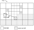
도 14는 일반적으로 1800에서 도시된 바와 같이 로컬 영역 인트라 블록 복사 모드의 일례를 예시하는 다이어그램이다. 로컬 영역 인트라 블록 복사 모드가 사용될 때, 왼쪽 및 현재 코딩 트리 유닛(coding tree unit; CTU)의 재구성된 픽셀만이 참조로서 사용되도록 허용된다.14 is a diagram illustrating an example of a local area intracblock copy mode, generally as shown at 1800. FIG. When the local area Intra block copy mode is used, only the reconstructed pixels of the left and current coding tree unit (CTU) are allowed to be used as references.
SCC와 자연적 비디오 코딩 사이에는 다른 차이가 있다. 자연적 비디오 코딩의 경우, 코딩 왜곡이 전체 화상에 분산한다. 그러나, 스크린 콘텐츠의 경우, PSNR(피크 신호 대 잡음비)이 전체 화상에 대해 상당히 높을 때에도 아티팩트를 더 잘 보이게 하는 강한 에지(strong edge) 주위에 에러가 일반적으로 국한된다. 따라서, 스크린 콘텐츠는 주관적인 품질 관점에서 인코딩하기가 더 어렵다.There is a difference between SCC and natural video coding. In the case of natural video coding, the coding distortion is distributed over the entire image. However, in the case of screen content, errors are generally localized around a strong edge that makes artifacts more visible, even when the PSNR (peak signal-to-noise ratio) is significantly higher for the entire picture. Thus, the screen content is more difficult to encode in terms of subjective quality.
인트라 블록 복사 모드를 사용하는 것은 블록 벡터의 시그널링을 필요로 한다. 전체 프레임 인트라 블록 복사 구성에서, 블록 벡터는 매우 커서, 인트라 블록 복사 모드에 대한 높은 오버헤드를 초래할 수 있다. 종종, 하나의 블록은 스크린 콘텐츠에 대해 매우 반복적인 패턴이 있기 때문에 다수의 유사한 매치(match)를 찾을 수 있다. 블록 벡터 코딩 효율을 향상시키기 위해, 다양한 예측 및 코딩 방법이 제안되었다 [R23]-[R28]. 현재 개시된 시스템 및 방법의 실시예는 인트라 블록 복사 코딩 효율을 향상시키기 위해 블록 벡터 도출을 이용한다. 이러한 개시물에서 논의되고 설명된 변형 중에는 (i) 인트라 블록 복사 병합 모드에서의 블록 벡터 도출 및 (ii) 명시적 블록 벡터 모드를 갖는 인트라 블록 복사에서의 블록 벡터 도출이 있다.Using intra block copy mode requires signaling of the block vector. In a full-frame intra-block copy configuration, the block vector is very large, which may result in a high overhead for the intra-block copy mode. Often, a number of similar matches can be found because one block has a very repetitive pattern for screen content. To improve block vector coding efficiency, various prediction and coding methods have been proposed [R23] - [R28]. Embodiments of the presently disclosed systems and methods utilize block vector derivation to improve Intra block copy coding efficiency. Among the variations discussed and described in this disclosure are (i) derivation of block vectors in intra block copy merging mode and (ii) derivation of block vectors in intra block copy with explicit block vector mode.
본 개시물에는 인트라 블록 복사 코딩을 위한 변위 정보 도출 방법에 대한 논의가 포함된다. 코딩 타입의 참조 블록에 따라, 도출된 블록 벡터 또는 움직임 벡터는 상이한 방식으로 사용될 수 있다. 하나의 방법은 도출된 BV를 IntraBC 병합 모드에서의 병합 후보로서 사용하는 것이다. 이러한 옵션은 제목이 "인트라 블록 복사 병합 모드(Intra Block Copy Merge Mode)"인 서브 섹션으로 아래에서 논의된다. 다른 방법은 일반적인 IntraBC 예측을 위해 도출된 BV/MV를 사용하는 것이다. 이러한 옵션은 제목이 "도출된 블록 벡터를 가진 인트라 블록 복사 모드(Intra Block Copy Mode with Derived Block Vector)"인 서브 섹션으로 아래에서 논의된다.This disclosure includes a discussion of methods for deriving displacement information for intrablock copy coding. Depending on the reference type of coding type, the derived block vector or motion vector may be used in a different manner. One method is to use the derived BV as a merging candidate in IntraBC merging mode. These options are discussed below as subsections with the title "Intra Block Copy Merge Mode". Another method is to use BV / MV derived for general IntraBC prediction. These options are discussed below as subsections with the title "Intra Block Copy Mode with Derived Block Vector".
도 16은 예시적인 블록 벡터 도출을 예시하는 다이어그램이다. 블록 벡터가 주어진 경우, 주어진 BV에 의해 나타내어진 참조 블록이 IntraBC 코딩된 블록인 경우에 제 2 블록 벡터가 도출될 수 있다. 도출된 블록 벡터는 식 (4)에서 계산된다. 도 16은 일반적으로 2000에서 이러한 종류의 블록 벡터 도출을 도시한다.16 is a diagram illustrating an exemplary block vector derivation. Given a block vector, a second block vector may be derived if the reference block represented by the given BV is an IntraBC coded block. The derived block vector is computed in Eq. (4). Figure 16 generally shows derivation of this kind of block vector in 2000.
BVd = BV0 + BVl (4) BVd = BV0 + BVl (4)
도 17은 예시적인 움직임 벡터 도출을 예시하는 다이어그램이다. 주어진 BV에 의해 나타내어진 블록이 인터 코딩된 블록이면, 움직임 벡터가 도출될 수 있다. 도 17은 일반적으로 2100에서의 MV 도출 경우를 도시한다. 도 17의 블록 B1이 단일 예측 모드인 경우, 블록 B0에 대한 정수 픽셀에서의 도출된 움직임 MVd는 다음과 같다:17 is a diagram illustrating an exemplary motion vector derivation. If the block represented by the given BV is an intercoded block, a motion vector may be derived. FIG. 17 generally shows the case of derivation of the MV at 2100. FIG. If block B1 in FIG. 17 is a single prediction mode, the derived motion MVd at the integer pixel for block B0 is:
MVd = BV0 + ((MV1+2)>>2) (5) MVd = BV0 + ((MV1 + 2) > 2) (5)
일부 실시예에서, 1/4 픽셀 해상도의 도출된 값 MVd_q는 다음과 같이 계산된다:In some embodiments, the derived value MVd_q of the quarter pixel resolution is calculated as:
MVd_q = (BV0<<2) + MV1 MVd_q = (BV0 < 2) + MV1
이러한 참조 화상은 B1의 참조 화상과 동일하다. HEVC에서, 보통의 움직임 벡터는 1/4 픽셀 정밀도(precision)를 갖고, 블록 벡터는 정수 정밀도(integer precision)를 갖는다. 도출된 움직임 벡터에 대한 정수 픽셀 움직임은 본 명세서에서 예로서 사용된다. 블록 B1이 양방향 예측 모드이면, 움직임 벡터 도출을 수행하는 두 방법이 있다. 하나는 두 방향에 대해 두 개의 움직임 벡터를 별개로 도출하고, 인덱스를 단방향 예측 모드와 동일하게 참조하는 것이다. 다른 하나는 더 작은 양자화 파라미터(더 높은 품질)로 참조 화상으로부터 움직임 벡터를 선택하는 것이다. 두 참조 화상이 동일한 양자화 파라미터를 갖는다면, POC(picture order of count) 거리(더 높은 상관)의 더 가까운 참조 화상으로부터 움직임 벡터를 선택할 수 있다. 다음의 논의는 복잡성을 줄이기 위해 양방향 예측을 단방향 예측으로 변환하는 제 2 방식을 이용하는 예를 사용한다.This reference image is the same as the reference image of B1. In HEVC, a normal motion vector has 1/4 pixel precision, and a block vector has integer precision. The integer pixel motion for the derived motion vector is used herein as an example. If the block B1 is a bidirectional prediction mode, there are two methods of performing motion vector derivation. One is to derive two motion vectors separately for two directions, and refer to the index in the same way as for the unidirectional prediction mode. And the other is to select a motion vector from the reference picture with a smaller quantization parameter (higher quality). If the two reference pictures have the same quantization parameter, a motion vector can be selected from a closer reference picture with a picture order of count (POC) distance (higher correlation). The following discussion uses an example using a second way of converting bidirectional predictions to unidirectional predictions to reduce complexity.
인트라Intra 블록 복사 병합 Merge block copy 모드mode ..
도 15는 인트라 블록 복사 병합을 위한 공간적 후보의 두 개의 예를 예시하는 다이어그램이다. HEVC 메인 프로파일 [R13] 및 범위 확장 [R17]에서, 인터 코딩 유닛 병합 모드는 움직임 정보를 직접 시그널링하지 않고, 인터 병합 후보 리스트의 인덱스를 디코더에 시그널링할 것이다. 인터 병합 후보 리스트는 결정적으로 인코더와 동일한 방식으로 구성될 것이다. 움직임 정보는 인덱스를 사용하여 후보 리스트로부터 도출된다. 도 15에서 1902로 번호가 매겨진 예에서, 5개의 공간적 인접한 블록과 하나의 시간적 배치된 블록이 있다. 인터 모드로 코딩된 블록만이 인터 병합 후보 리스트에 부가될 것이다. 후보 리스트가 공간적 및 시간적 인접한 블록으로 가득 차 있지 않으면, 2개의 리스트에서의 기존의 병합 후보와 제로 움직임을 조합함으로써 양방향 예측 움직임이 첨가될 것이다.15 is a diagram illustrating two examples of spatial candidates for intra block copy merging. In the HEVC main profile [R13] and range extension [R17], the intercoding unit merging mode will signal the index of the inter-merging candidate list to the decoder without directly signaling the motion information. The inter-merging candidate list will be conclusively constructed in the same manner as the encoder. The motion information is derived from the candidate list using an index. In the example numbered 1902 in Fig. 15, there are five spatial adjacent blocks and one temporally arranged block. Only blocks coded in inter mode will be added to the inter-merging candidate list. If the candidate list is not full of spatially and temporally adjacent blocks, a bidirectional predictive motion will be added by combining the existing merging candidate and zero motion in two lists.
인트라 블록 복사 병합 모드의 경우, 병합 모드를 적용하는 유사한 방법이 수행된다. BV 정보는 명시적으로 코딩되지 않고, 병합 후보 인덱스는 코딩된다. HEVC SCC 확장(SCM-1.0) [R31]에서, BV는 마지막으로 코딩된 BV를 예측자(predictor)로서 사용하여 차등 코딩(differential coding)으로 코딩된다. BV 후보 리스트 구성에서, BV 예측자가 먼저 체크된다. BV 예측자가 현재 CU에 대해 유효하면, 제 1 병합 후보로서 부가된다. 그 다음, 도 15의 1902 및 1904로 번호가 매겨진 예에서, 5개의 공간적 블록이 체크되고; 유효한 BV는 (1) 공간적 인접한 블록이 IntraBC 코딩되어 BV를 갖는 경우, (2) BV가 현재 CU에 대해 유효한 경우(예를 들어, BV에 의해 나타내어진 참조 블록이 화상 경계를 벗어나지 않고 이미 코딩된 경우), 및 (3) BV가 현재 후보 리스트에 이미 나타나지 않은 경우의 순서대로 부가된다. 병합 후보 리스트가 가득 차 있지 않으면, BV는 이미 리스트 내에 있는 유효한 BV로 도출된다. 일 실시예에서, 식 (4)의 도출된 블록 벡터만이 고려되고, 식 (5)의 도출된 움직임 벡터는 고려되지 않으며; 이러한 예에서, 후보 리스트 내의 모든 병합 후보는 인트라 블록 복사 모드에 대응하는 블록 벡터이다.In the intra block copy merge mode, a similar method of applying the merge mode is performed. The BV information is not explicitly coded, and the merge candidate indexes are coded. In the HEVC SCC extension (SCM-1.0) [R31], the BV is coded with differential coding using the last coded BV as a predictor. In the BV candidate list configuration, the BV predictor is checked first. If the BV predictor is valid for the current CU, it is added as the first merging candidate. Then, in the example numbered 1902 and 1904 in Fig. 15, five spatial blocks are checked; The valid BVs are: (1) Spatially adjacent blocks are IntraBC coded to have BV; (2) BV is valid for the current CU (e.g., the reference block indicated by BV is already coded , And (3) BV is not already present in the current candidate list. If the merge candidate list is not full, the BV is already derived to a valid BV in the list. In one embodiment, only the derived block vector of equation (4) is considered, and the derived motion vector of equation (5) is not considered; In this example, all merge candidates in the candidate list are block vectors corresponding to the intra block copy mode.
복잡한 설계에 대해, 식 (5)으로부터 도출된 움직임 벡터는 함께 혼합될 수 있고, 블록 벡터와 함께 병합 후보에 부가될 수 있다. 다른 실시예는 각각의 후보 블록 벡터(BVo)에 대한 것이고, BVo에 기초하여 도출된 BVd 또는 MVd가 유효하면, 후보 블록을 BVo 및 BVd/MVd를 가진 양방향 예측 모드로서 간주할 것이며, 여기서 양방향 예측은 블록 벡터(BV0)를 적용함으로써 획득된 제 1 예측을 도출된 블록 또는 움직임 벡터(BVd/MVd)를 적용함으로써 획득된 제 2 예측과 평균함으로써 획득된다.For a complex design, the motion vectors derived from equation (5) can be mixed together and added to the merging candidate along with the block vector. Another embodiment is for each candidate block vector (BV o ), and if the BV d or MV d derived based on BV o is valid, the candidate block is set as a bidirectional prediction mode with BV o and BV d / MV d Where bidirectional prediction is obtained by averaging a first prediction obtained by applying a block vector (BV 0 ) with a second prediction obtained by applying the derived block or motion vector (BV d / MV d ).
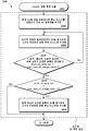
도 18a 및 도 18b는 모두 인트라 블록 복사 병합 후보 리스트 구성의 예시적인 방법의 흐름도이다. 예시적인 방법(2200)은 "IntraBC 병합 후보 도출"인 단계(2202)에서 시작한다. 그 다음, 방법은 "공간적 BV 후보 생성(Spatial BV Candidates Generation)"이라고 표시된 점선 박스로 진행하고, 특히 "현재 CU에 대해 유효하다면 후보 리스트를 병합하기 위해 BV 예측자를 부가함(Add the BV predictor to merge candidate list if it is valid for current CU)"인 단계(2204)로 진행한다. 그 다음, 처리는 "공간적 인접한 블록으로부터 BV를 체크하여, 그것이 유효하면 병합 후보 리스트에 부가함(Check the BV from spatial neighboring blocks, add it to merge candidate list if it is valid)"인 단계(2206)로 진행한다.18A and 18B are flow charts of an exemplary method of constructing an intra-block copy merge candidate list. The
그 다음, 방법은 다음의 조건: "( (왼쪽, 최상부, 오른쪽 최상부, 왼쪽 최하부 인접한 블록이 체크됨(left, top, top right, bottom left Neighboring blocks are checked)) || (num_of_cand_list >= max_num_of_merge_cand) )?"이 평가되는 판정 박스(2208)로 진행한다. 2208에서 조건이 거짓으로 결정되면, 처리는 단계(2206)로 복귀한다.Then, the method proceeds to the next condition: " ((left, top, right top, left bottom left neighbor block checked (left, top, top right, bottom left neighboring blocks are checked) || (num_of_cand_list> = max_num_of_merge_cand) )? "Is evaluated. If the condition is determined to be false at 2208, processing returns to step 2206. [
대신에 2208에서의 조건이 참으로 결정되면, 처리는 다음의 조건: "(num_of_cand_list <max_num_of_merge_cand -1)?"이 평가되는 판정 박스(2210)로 진행한다. 2210에서의 조건이 참으로 결정되면, 처리는 "왼쪽 최상부 인접한 블록의 BV를 체크하여, 그것이 유효하면 병합 후보 리스트에 부가함(Check the BV of top left neighboring block, add it to merge candidate list if it is valid.)"인 단계(2212)로 진행한다. 2210에서의 조건이 거짓으로 결정되면, 단계(2212)는 바이패스된다. 어느 쪽이든, 그 다음 처리는 도 18b로 진행하고, 제목이 "BVd 후보 생성(BVd Candidates Generation)"인 점선 박스, 구체적으로는 다음의 조건: "( (체크된 리스트 내의 모든 공간적 BV 후보(all spatial BV candidates in the list checked)) || (num_of_cand_list >= max_num_of_merge_cand)?"이 평가되는 판정 박스(2216)로 진행한다.Instead, if the condition at 2208 is determined to be true, processing proceeds to
2216에서의 조건이 참으로 결정되면, 처리는 2224에서 종료한다. 2216에서의 조건이 거짓으로 결정되면, 처리는 "후보 리스트로부터 하나의 공간적 BV를 취하고, BVd를 도출함(Take one spatial BV from candidate list, and derive BVd)."인 단계(2218)로 진행한다.If the condition at 2216 is true, the process ends at 2224. If the condition at 2216 is determined to be false, the process proceeds to step 2218, which is "Take one spatial BV from the candidate list and derive BVd (from candidate list, and derive BVd)" .
다음으로, 처리는 다음의 조건: "BVd가 유효한가(BVd is valid)?"이 평가되는 판정 박스(2220)로 진행한다. 2220에서의 조건이 참으로 결정되면, 처리는 "BVd를 병합 후보 리스트에 부가함(add BVd to merge candidate list)"하는 단계(2222)로 진행한다. 대신에 2220에서의 조건이 거짓으로 결정되면, 처리는 판정 박스(2216)로 복귀한다.Next, the process proceeds to the
도출된 블록 벡터를 가진 With derived block vector 인트라Intra 블록 복사 Copy block 모드mode ..
정상적인 인트라 블록 복사 모드에서, 블록 벡터는 코딩 유닛 내의 각각의 예측 유닛에 대해 명시적으로 시그널링될 것이다. 일부 실시예에서, 이러한 모드는 시그널링된 블록 벡터 또는 도출된 블록 벡터가 IntraBC 예측에 사용되는지를 나타내는 플래그를 부가함으로써 확장된다. 플래그가 0이면, 시그널링된 블록 벡터는 IntraBC 예측을 위해 사용되고, BV 도출을 적용할 필요가 없다. 플래그가 1이면, BV 또는 MV는 시그널링된 블록 벡터에 기초하여 식 (4) 또는 식 (5)을 이용하여 도출되고, 도출된 BV 또는 MV는 인트라 블록 복사 예측 또는 움직임 보상된 예측을 위해 사용될 것이다.In normal intra block copy mode, the block vector will be explicitly signaled for each prediction unit in the coding unit. In some embodiments, this mode is extended by adding a flag indicating whether the signaled block vector or derived block vector is used for IntraBC prediction. If the flag is 0, then the signaled block vector is used for IntraBC prediction and there is no need to apply BV derivation. If the flag is 1, the BV or MV is derived using Eq. (4) or Eq. (5) based on the signaled block vector and the derived BV or MV will be used for intra-block copy prediction or motion compensated prediction .
다른 실시예는 2개의 플래그를 정상적인 IntraBC 모드에 부가하는 것이다. 제 1 플래그는 BV 도출 프로세스가 적용되는지 여부를 나타내는데 사용된다. 제 1 플래그가 1이면, 제 2 플래그는 단방향 예측이 사용되는지 양방향 예측이 사용되는지를 나타내기 위해 코딩된다. 제 2 플래그가 0이면, 도출된 BV 또는 MV만이 인트라 블록 복사 예측 또는 움직임 보상된 예측을 위해 사용된다. 그렇지 않으면, 제 2 플래그가 1이면, 시그널링된 BV는 제 1 예측을 생성하는데 사용되고, 도출된 BV 또는 MV는 제 2 예측을 생성하는데 사용되며; 최종 예측은 양방향 예측 모드와 유사하게 이러한 2개의 예측을 평균함으로써 생성된다.Another embodiment is to add two flags to the normal IntraBC mode. The first flag is used to indicate whether or not the BV derivation process is applied. If the first flag is 1, the second flag is coded to indicate whether unidirectional prediction is used or bidirectional prediction is used. If the second flag is 0, only the derived BV or MV is used for intra block copy prediction or motion compensated prediction. Otherwise, if the second flag is 1, the signaled BV is used to generate the first prediction and the derived BV or MV is used to generate the second prediction; The final prediction is generated by averaging these two predictions in a manner similar to the bidirectional prediction mode.
블록 벡터 도출에 대한 메모리 액세스 대역폭 감소.Reduced memory access bandwidth for block vector derivation.
블록 벡터 도출은 도 16 및 도 17의 블록 B1의 정보와 같은 블록 코딩 모드 및 블록 벡터/움직임 벡터에 관한 정보를 사용하여 동작한다. 디코더 칩 설계에 대해, 코딩된 모든 블록의 모드/BV/움직임 정보를 저장하는 두 가지 방식이 있다. 하나는 정보를 외부 메모리에 저장하는 것이다. 이러한 기술은 외부 메모리에 대한 액세스를 필요로 하며, 따라서 메모리 액세스 대역폭을 증가시킨다. 다른 기술은 온칩 메모리에 정보를 캐시하는 것이며, 이는 캐시 크기를 증가시킨다.The derivation of the block vector operates using the information about the block coding mode and the block vector / motion vector, such as the information of the block B1 of Figs. For the decoder chip design, there are two ways to store the mode / BV / motion information of all coded blocks. One is to store the information in external memory. This technique requires access to external memory, thus increasing memory access bandwidth. Another technique is to cache information in on-chip memory, which increases cache size.
저장될 필요가 있는 정보의 양을 감소시키기 위한 2개의 예시적인 방법이 본 명세서에서 설명된다. 하나는 해당 정보를 거친 입도(coarse granularity)로 저장하는 것이다. HEVC에서, 원래의 BV/MV 정보는 4×4 블록 크기에 기초하여 저장된다. 메모리 크기는 더 큰 블록 크기, 예를 들어, 16×16 블록 크기에 기초하여 압축된 형태로 원래의 BV/MV 정보를 저장함으로써 크게 감소될 수 있다. 16×16 블록 크기가 사용되면, 필요한 BV 저장 공간은 HEVC에서의 압축된 움직임과 동일한 입도를 갖는다. 이러한 방식으로, 합리적인 크기로 이러한 데이터를 캐시할 수 있다. 제 2 솔루션은 코딩된 블록의 정보를 이미 코딩된 모든 블록 대신에 제한된 범위에서 캐시하는 것이다. 예를 들어, 디코더는 현재 CTU 행에 관한 정보와 현재 CTU 행 위에 있는 제한된 수의 코딩된 인접한 CTU 행만을 캐시할 수 있다. 도 16 및 도 17에서 제 1 BV에 의해 나타낸 블록(B1)이 디코더가 캐시하는 범위 밖에 있으면, 이러한 BV는 유효하지 않은 것으로 간주될 것이고, BV/MV 도출은 적용되지 않을 것이다.Two exemplary methods for reducing the amount of information that need to be stored are described herein. One is to store the information in coarse granularity. In HEVC, the original BV / MV information is stored based on a 4x4 block size. The memory size can be greatly reduced by storing the original BV / MV information in a compressed form based on a larger block size, for example, a 16x16 block size. When a 16x16 block size is used, the required BV storage space has the same granularity as the compressed motion in the HEVC. In this way, you can cache this data at reasonable size. The second solution is to cache the information of the coded block in a limited range instead of all blocks already coded. For example, the decoder can cache information about the current CTU row and only a limited number of coded contiguous CTU rows currently on the CTU row. If the block B1 indicated by the first BV in Figures 16 and 17 is outside the range cached by the decoder, then this BV will be considered invalid and the BV / MV derivation will not be applied.
코딩 Coding 신택스Syntax 및 And 세맨틱스Semantics (semantics).(semantics).
HEVC 범위 확장 드래프트(draft) [R17]의 현재 신택스 설계에 기초하여 도출된 블록 벡터를 가진 인트라 블록 복사 병합 및 인트라 블록 복사로 코딩되는 CU를 시그널링하기 위해 새로운 신택스 요소가 제안되었다. 이러한 섹션에서 논의된 제안된 팔레트 코딩 방법은 부가적인 신택스를 도입함으로써 비트 스트림으로 시그널링될 수 있다. 다음의 표(표 2)는 제안된 신택스 요소를 나타내고, HEVC 범위 확장 드래프트 [R17]에 대한 변경 사항은 [10], [12], [13], [14], [17], [27], [28], [29], [40], [41] 및 [42]으로 번호가 매겨진 라인에 포함된다.A new syntax element has been proposed for signaling CUs coded with intra block copy merge and intra block copy with derived block vectors based on the current syntax design of the HEVC range extension draft [R17]. The proposed palette coding method discussed in this section can be signaled to the bitstream by introducing additional syntax. 10], [12], [13], [14], [17], [27] for the HEVC range extension draft [R17] are shown in the following table (Table 2) , [28], [29], [40], [41] and [42]
신택스Syntax


표 2와 관련하여, 다음의 것이 언급된다:With reference to Table 2, the following are mentioned:
1과 동일한 intra _bc_merge_flag[x0][y0]는 현재 코딩 유닛이 병합 모드로 코딩되고, 블록 벡터가 병합 후보로부터 선택된다는 것을 지정한다. 0과 동일한 intra_bc_merge_flag[x0][y0]는 코딩 유닛이 병합 모드로 코딩되지 않고, 현재 코딩 유닛의 블록 벡터가 명시적으로 코딩된다는 것을 지정한다. 존재하지 않으면, intra_bc_merge_flag의 값은 0과 동일한 것으로 추론된다. 어레이 인덱스 xO, yO는 화상의 왼쪽 최상부 휘도 샘플에 대한 고려된 코딩 블록의 왼쪽 최상부 휘도 샘플의 위치(x0, y0)를 지정한다.1 and the same intra _bc_merge_flag [x0] [y0] specifies that the current coding unit is encoded in the merge mode, the block vector is selected from the merge candidates. Intra_bc_merge_flag [x0] [y0], which is equal to 0, specifies that the coding unit is not coded in the merging mode, and the block vector of the current coding unit is explicitly coded. If it does not exist, the value of intra_bc_merge_flag is deduced to be equal to zero. The array index xO, yO specifies the position (x0, y0) of the leftmost top luminance sample of the considered coding block for the leftmost top luminance sample of the picture.
intra _bc_merge_index[xO][yO]는 현재 코딩 유닛의 블록 벡터가 동일한 병합 후보 중에서 인덱스를 지정한다. intra_bc_merge_index[xO][yO]는 0 내지 인트라 블록 복사 병합 후보의 최대 수 마이너스 1의 범위(range of 0 to maximal number of intra block copying merge candidates minus 1) 내에 있어야 한다. 어레이 인덱스 xO, yO는 화상의 왼쪽 최상부 휘도 샘플에 대한 고려된 코딩 블록의 왼쪽 최상부 휘도 샘플의 위치(x0, y0)를 지정한다. intra _bc_merge_index [xO] [yO] is a block vector of the current coding unit specifies the index candidates from the same merge. intra_bc_merge_index [xO] [yO] must be within the range of 0 to the maximum number of intra block copy merge candidates (range of 0 to maximal number of intra block copying merge candidates minus 1). The array index xO, yO specifies the position (x0, y0) of the leftmost top luminance sample of the considered coding block for the leftmost top luminance sample of the picture.
1과 동일한 intra _bc_ bv _derivation_flag[x0][y0]는 도출된 BV 또는 MV가 현재 PU 예측을 위해 사용된다는 것을 지정한다.1, the same intra _bc_ bv _derivation_flag and [x0] [y0] specifies that the derived BV or MV are used for predicting the current PU.
추가의 예시적인 Additional illustrative 실시예Example ..
예시적인 실시예에서, 도출된 블록 벡터가 생성되고, 도출된 블록 벡터는 인트라 블록 복사 병합 모드에서 병합 후보로서 사용된다. 이러한 일부 방법에서, 도출된 블록 벡터 BVd는 블록 벡터 BV0가 주어지면 BVd = BV0 + BV1에 따라 결정된다.In the exemplary embodiment, the derived block vector is generated, and the derived block vector is used as the merging candidate in intra block copy merge mode. In some of these methods, the derived block vector BVd is determined according to BVd = BV0 + BV1 given the block vector BV0.
다른 예시적인 실시예에서, 도출된 움직임 벡터가 생성되고, 도출된 움직임 벡터는 인트라 블록 복사 병합 모드에서 병합 후보로서 사용된다. 이러한 일부 방법에서, 정수 픽셀 유닛의 도출된 움직임 벡터 MVd는 블록 벡터 BV0가 주어지면 MVd = BV0+((MV1+2)>>2)에 따라 결정된다.In another exemplary embodiment, the derived motion vector is generated, and the derived motion vector is used as a merge candidate in the intra block copy merge mode. In some of these methods, the derived motion vector MVd of the integer pixel unit is determined according to MVd = BV0 + ((MV1 + 2) " 2) given block vector BV0.
예시적인 실시예에서, 도출된 블록 벡터가 생성되고, 도출된 블록 벡터는 인트라 블록 복사 방법을 사용하여 정상적인 IntraBC 예측을 위해 사용된다.In an exemplary embodiment, the derived block vector is generated, and the derived block vector is used for normal IntraBC prediction using the intra block copy method.
다른 예시적인 실시예에서, 도출된 움직임 벡터가 생성되고, 도출된 움직임 벡터는 움직임 보상 예측 방법을 사용하여 정상적인 IntraBC 예측을 위해 사용된다.In another exemplary embodiment, the derived motion vector is generated and the derived motion vector is used for normal IntraBC prediction using the motion compensated prediction method.
예시적인 실시예에서, 블록 벡터(BV) 후보 리스트가 형성된다. 도출된 BV(BVd)가 생성되고, BVd가 후보 리스트에 부가된다.In an exemplary embodiment, a block vector (BV) candidate list is formed. The derived BV (BVd) is generated, and BVd is added to the candidate list.
이러한 일부 실시예에서, BV 후보 리스트의 형성은 BV 예측자가 현재의 코딩 유닛(CU)에 대해 유효하면 BV 예측자를 부가하고, 5개의 공간 블록을 체크하며, 유효한 각각의 공간 블록 BV를 부가하는 것을 포함한다. 이러한 일부 실시예에서, 공간 블록 BV는 (i) 공간적 인접한 블록이 IntraBC 코딩되고, (ii) BV가 현재 CU에 대해 유효하며, (iii) BV가 현재 후보 리스트에 이미 나타나지 않은 경우에만 부가된다. 이러한 일부 실시예에서, BVd는 병합 후보 리스트가 가득 차 있지 않은 경우에만 생성된다. BVd는 후보 리스트에 부가되기 전에 유효성에 대해 체크될 수 있다. 일부 실시예에서, 생성되는 BVd는 BVd = BV0 + BV1에 따라서만 도출된다. 이러한 일부 방법에서, 도출된 움직임 벡터(MVd)가 생성되고, MVd가 후보 리스트에 부가된다. 일부 실시예에서, BVd는 (i) BVd = BV0 + BV1 및 (ii) MVd = BV0 +((MV1+2)>>2) 둘 다에 따라 도출된다. 일부 실시예에서, 후보 블록은 BV0 및 BVd/MVd를 가진 양방향 예측 모드로서 처리된다. 양방향 예측은 먼저 블록 벡터(BV0)를 적용함으로써 획득된 제 1 예측을 블록 또는 움직임 벡터(BVd/MVd)를 적용함으로써 획득된 제 2 예측과 평균함으로써 획득될 수 있다.In some such embodiments, the formation of a BV candidate list may be accomplished by adding a BV predictor, checking five spatial blocks, and adding each valid spatial block BV if the BV predictor is valid for the current coding unit (CU) . In some such embodiments, the spatial block BV is added only if (i) the spatial adjacent block is IntraBC coded, (ii) the BV is valid for the current CU, and (iii) the BV is not already present in the current candidate list. In some such embodiments, BVd is generated only if the merge candidate list is not full. BVd may be checked for validity before being added to the candidate list. In some embodiments, the generated BVd is derived only according to BVd = BV0 + BV1. In some of these methods, the derived motion vector MVd is generated and MVd is added to the candidate list. In some embodiments, BVd is derived according to both (i) BVd = BV0 + BV1 and (ii) MVd = BV0 + ((MV1 + 2) > In some embodiments, the candidate block is treated as a bidirectional prediction mode with BV0 and BVd / MVd. Bi-directional prediction can be obtained by first averaging the first prediction obtained by applying the block vector (BV0) with the second prediction obtained by applying the block or motion vector (BVd / MVd).
예시적인 실시예에서, 비디오 코딩된 비트 스트림이 수신되고, 시그널링된 블록 벡터 또는 도출된 블록 벡터가 IntraBC 예측에 사용되는지를 나타내는 플래그가 비트 스트림에서 식별된다. 플래그가 제 1 값이면, 시그널링된 블록 벡터는 IntraBC 예측에 사용된다. 플래그가 제 2 값이면, BV 또는 MV는 시그널링된 블록 벡터에 기초하여 도출된다. 이러한 일부 방법에서, 도출된 BV 또는 MV는 인트라 블록 복사 예측 또는 움직임 보상 예측에 사용된다.In an exemplary embodiment, a video coded bitstream is received and a flag indicating whether the signaled block vector or derived block vector is used for IntraBC prediction is identified in the bitstream. If the flag is the first value, the signaled block vector is used for IntraBC prediction. If the flag is a second value, the BV or MV is derived based on the signaled block vector. In some of these methods, the derived BV or MV is used for Intra block copy prediction or motion compensation prediction.
다른 예시적인 실시예에서, 코딩된 비디오 비트 스트림이 수신된다. 비트 스트림에서의 제 1 플래그는 시그널링된 블록 벡터 또는 도출된 블록 벡터가 IntraBC 예측에 사용되는지를 나타내는 것으로 식별된다. 비트 스트림에서의 제 2 플래그는 단방향 예측 또는 양방향 예측이 사용되는지를 나타내는 것으로 식별된다.In another exemplary embodiment, a coded video bitstream is received. The first flag in the bitstream is identified as indicating whether the signaled block vector or derived block vector is used for IntraBC prediction. The second flag in the bitstream is identified as indicating whether unidirectional prediction or bidirectional prediction is used.
이러한 일부 실시예에서, 제 1 플래그가 1이고, 제 2 플래그가 0이면, 도출된 BV/MV만이 인트라 블록 복사 예측 또는 움직임 보상된 예측을 위해 사용된다. 제 1 플래그가 1이고, 제 2 플래그가 1이면, 시그널링된 BV는 제 1 예측을 생성하는데 사용되고, 도출된 BV/MV는 제 2 예측을 생성하는데 사용되며, 최종 예측은 이러한 2개의 예측을 평균함으로써 생성된다.In some such embodiments, if the first flag is 1 and the second flag is 0, then only the derived BV / MV is used for intra block copy prediction or motion compensated prediction. If the first flag is 1 and the second flag is 1, then the signaled BV is used to generate the first prediction and the derived BV / MV is used to generate the second prediction, .
예시적인 실시예에서, 원래의 BV/MV 정보는 더 큰 블록 크기에 기초하여 BV/MV 정보를 저장함으로써 압축된다. 더 큰 블록 크기는 예를 들어 16×16 블록 크기일 수 있다.In an exemplary embodiment, the original BV / MV information is compressed by storing BV / MV information based on a larger block size. The larger block size may be, for example, a 16x16 block size.
다른 예시적인 실시예에서, 디코더는 이미 코딩된 모든 블록보다 적은 제한된 범위 내의 코딩된 블록의 정보를 캐시하는데 사용된다. 이러한 일부 방법에서, 디코더는 현재 CTU 행의 정보 및 현재 CTU 행보다 많은 미리 결정된 수의 코딩된 인접한 CTU 행의 정보만을 캐싱한다.In another exemplary embodiment, a decoder is used to cache information of coded blocks within a limited range that is less than all blocks that are already coded. In some such methods, the decoder only caches information of the current CTU row and information of a predetermined number of coded contiguous CTU rows greater than the current CTU row.
예시적인 실시예에서, 예측 벡터를 도출하는 비디오 코딩 방법이 제공된다. 방법은 비디오 블록의 예측을 위한 제 1 후보 블록 벡터를 식별하는 단계를 포함하며, 제 1 후보 블록 벡터는 제 1 후보 블록을 나타낸다. 제 1 후보 블록과 관련된 적어도 제 1 예측 벡터가 식별된다. 도출된 예측 벡터는 제 1 후보 블록 벡터 및 제 1 예측 벡터로부터 생성되고, 비디오 블록은 도출된 예측 벡터를 사용하여 코딩된다. 일부 실시예에서, 도출된 예측 벡터를 사용하는 비디오 블록의 코딩은 도출된 예측 벡터가 나타내는 제 2 후보 블록을 식별하고, 제 2 후보 블록을 사용하여 비디오 블록을 예측하는 것을 포함한다.In an exemplary embodiment, a video coding method for deriving a prediction vector is provided. The method includes identifying a first candidate block vector for prediction of a video block, wherein the first candidate block vector represents a first candidate block. At least a first prediction vector associated with the first candidate block is identified. The derived prediction vector is generated from the first candidate block vector and the first prediction vector, and the video block is coded using the derived prediction vector. In some embodiments, coding of a video block using the derived prediction vector includes identifying a second candidate block represented by the derived prediction vector, and predicting the video block using the second candidate block.
일부 실시예에서, 비디오 블록을 코딩하는 단계는 비트 스트림에서 제 1 후보 블록 벡터를 시그널링하는 단계를 포함한다. 일부 실시예에서, 비디오 블록을 코딩하는 단계는 비트 스트림에서 제 1 예측 벡터를 시그널링하는 단계를 더 포함한다. 일부 실시예에서, 비디오 블록을 코딩하는 단계는 비트 스트림에서 플래그를 시그널링하는 단계를 더 포함하며, 플래그의 제 1 값은 도출된 예측 벡터가 비디오 블록을 코딩하는데 사용되는 것을 나타내고, 플래그의 제 2 값은 제 1 후보 블록 벡터가 비디오 블록을 코딩하는데 사용되는 것을 나타낸다. 일부 실시예에서, 비트 스트림에서 입력 비디오 블록을 인코딩하는 단계는 병합 후보 리스트에서 도출된 예측 벡터를 식별하는 인덱스를 비트 스트림에서 인코딩하는 단계를 포함한다.In some embodiments, coding a video block includes signaling a first candidate block vector in the bitstream. In some embodiments, coding the video block further comprises signaling a first prediction vector in the bitstream. In some embodiments, coding the video block further comprises signaling a flag in the bitstream, wherein a first value of the flag indicates that the derived prediction vector is used to code the video block, and the second value of the flag Value indicates that the first candidate block vector is used to code the video block. In some embodiments, encoding the input video block in the bitstream includes encoding an index in the bitstream that identifies the prediction vector derived from the merging candidate list.
일부 실시예에서, 도출된 예측 벡터는 제 1 후보 블록 벡터 및 제 1 예측 벡터를 부가함으로써 생성된다. 제 1 후보 블록 벡터 및 제 1 예측 벡터가 상이한 정밀도를 갖는 경우, 제 1 블록 벡터 및 제 1 예측 벡터의 부가는 이러한 두 벡터를 동일한 정밀도로 정렬한 후에 수행될 수 있다.In some embodiments, the derived prediction vector is generated by adding a first candidate block vector and a first prediction vector. When the first candidate block vector and the first predictive vector have different accuracies, the addition of the first block vector and the first predictive vector may be performed after aligning these two vectors with the same precision.
일부 실시예에서, 비디오 코딩 방법은 병합 후보 리스트를 생성하는 단계와, 도출된 예측 벡터를 병합 후보 리스트에 삽입하는 단계를 더 포함한다. 이러한 일부 실시예에서, 도출된 예측 벡터가 유효한지에 대한 결정이 이루어지고, 도출된 예측 벡터가 유효한 것으로 결정한 후에만 도출된 예측 벡터는 병합 후보 리스트에 삽입된다. 도출된 예측 벡터를 사용하여 비디오 블록을 코딩하는 단계는 병합 후보 리스트에서 도출된 예측 벡터를 식별하는 인덱스를 제공하는 단계를 포함한다. 일부 실시예에서, 도출된 예측 벡터가 유효한지의 결정은 도출된 예측 벡터가 나타내는 제 2 후보 블록을 식별하고, 제 2 후보 블록의 모든 샘플이 이용 가능한지를 결정하는 것을 포함한다. 도출된 예측 벡터는 제 2 후보 블록의 모든 샘플이 이용 가능하다면 유효한 것으로 결정된다. 도출된 예측 벡터는 제 2 후보 블록의 적어도 하나의 샘플이 이용 가능하지 않다면 유효하지 않은 것으로 결정된다. 일부 실시예에서, 제 2 후보 블록의 샘플은 다음 것: 샘플이 아직 코딩되지 않았거나, 샘플이 상이한 슬라이스 또는 상이한 타일(tile)에 있거나, 샘플이 비디오 화상 경계에서 벗어난 것 중 하나가 참이라면 이용 가능하지 않다.In some embodiments, the video coding method further comprises generating a merging candidate list and inserting the derived prediction vector into the merging candidate list. In some such embodiments, a determination is made as to whether the derived predicted vector is valid, and the derived predicted vector is inserted into the merge candidate list only after determining that the derived predicted vector is valid. Coding the video block using the derived prediction vector includes providing an index that identifies the prediction vector derived from the merging candidate list. In some embodiments, determining whether the derived prediction vector is valid includes identifying a second candidate block represented by the derived prediction vector, and determining if all samples of the second candidate block are available. The derived prediction vector is determined to be valid if all samples of the second candidate block are available. The derived prediction vector is determined to be invalid if at least one sample of the second candidate block is not available. In some embodiments, the sample of the second candidate block may be one of the following: use if the sample is not yet coded, if the sample is on a different slice or on a different tile, or if one of the samples is off video image boundaries is true not possible.
예시적인 실시예에서, 비디오를 인코딩하는 비트 스트림으로부터 코딩된 비디오 블록을 디코딩하는 방법이 제공된다. 적어도 제 1 후보 블록 벡터는 입력 비디오 블록의 예측을 위해 식별되고, 제 1 후보 블록 벡터는 제 1 후보 블록을 나타낸다. 제 1 후보 블록과 관련된 적어도 제 1 예측 벡터가 식별된다. 도출된 예측 벡터는 제 1 블록 벡터 및 제 1 예측 벡터로부터 생성되고, 코딩된 비디오 블록은 도출된 예측 벡터를 사용하여 디코딩된다. 이러한 일부 실시예에서, 제 1 후보 블록 벡터의 식별은 비트 스트림에서 시그널링된 제 1 후보 블록 벡터를 수신하는 것을 포함한다.In an exemplary embodiment, a method of decoding a coded video block from a bitstream encoding video is provided. At least a first candidate block vector is identified for prediction of an input video block, and a first candidate block vector represents a first candidate block. At least a first prediction vector associated with the first candidate block is identified. The derived prediction vector is generated from the first block vector and the first prediction vector, and the coded video block is decoded using the derived prediction vector. In some such embodiments, the identification of the first candidate block vector comprises receiving a first candidate block vector signaled in the bitstream.
이러한 일부 실시예에서, 도출된 예측 벡터를 사용하는 코딩된 비디오 블록의 디코딩은 입력 비디오 블록이 도출된 예측 벡터로 인코딩되는 것을 나타내는 플래그를 비트 스트림에서 수신하는 것에 응답하여 수행된다.In some such embodiments, decoding of the coded video block using the derived prediction vector is performed in response to receiving in the bitstream a flag indicating that the input video block is encoded with the derived prediction vector.
일부 실시예에서, 제 1 후보 블록 벡터의 식별은 제 1 블록 벡터 병합 후보의 식별을 포함한다. 일부 실시예에서, 도출된 예측 벡터는 도출된 예측 벡터 병합 후보이고, 도출된 예측 벡터 병합 후보를 사용하여 코딩된 비디오 블록의 디코딩은 도출된 예측 벡터 병합 후보를 식별하는 인덱스를 비트 스트림에서 수신하는 것에 응답하여 수행된다.In some embodiments, the identification of the first candidate block vector includes identification of the first block vector merging candidate. In some embodiments, the derived prediction vector is a derived predicted vector merge candidate, and the decoding of the coded video block using the derived predicted vector merge candidate is performed by receiving an index identifying the derived predicted vector merge candidate in the bitstream Lt; / RTI >
예시적인 실시예에서, 입력 비디오 블록을 포함하는 비디오를 인코딩하는 비트 스트림을 생성하기 위한 비디오 인코딩 방법이 제공된다. 입력 비디오 블록의 인접한 블록이 식별된다. 인접한 블록은 예를 들어 입력 비디오 블록의 왼쪽, 최상부 또는 왼쪽 최상부 인접 블록일 수 있다. 인접한 블록과 연관된 제 1 블록 벡터가 식별되며, 여기서 제 1 블록 벡터는 제 1 후보 블록을 나타낸다. 제 1 후보 블록과 연관된 제 2 블록 벡터가 식별된다. 도출된 블록 벡터는 제 1 블록 벡터 및 제 2 블록 벡터를 부가함으로써 생성되고, 제 1 예측 블록은 도출된 블록 벡터를 사용하여 입력 비디오 블록의 예측을 위해 생성된다.In an exemplary embodiment, a video encoding method is provided for generating a bitstream that encodes video comprising an input video block. Adjacent blocks of the input video block are identified. Adjacent blocks may be, for example, the left, top, or leftmost top adjacent block of the input video block. A first block vector associated with an adjacent block is identified, wherein the first block vector represents a first candidate block. A second block vector associated with the first candidate block is identified. The derived block vector is generated by adding a first block vector and a second block vector, and a first prediction block is generated for prediction of the input video block using the derived block vector.
이러한 일부 실시예에서, 입력 비디오 블록의 인코딩은 제 3 블록 벡터를 사용하여 입력 비디오 블록의 예측을 위한 적어도 제 2 예측 블록을 생성하는 것을 더 포함한다. 제 1 예측 블록 및 제 2 예측 블록은 비교되고, 예측 블록 및 연관된 블록 벡터는 인코딩 메트릭에 기초하여 선택된다. 인코딩 메트릭은 예를 들어 라그랑지안 레이트 왜곡 비용(Lagrangian rate-distortion cost)일 수 있다.In some such embodiments, the encoding of the input video block further comprises generating at least a second prediction block for prediction of the input video block using the third block vector. The first prediction block and the second prediction block are compared, and the prediction block and the associated block vector are selected based on the encoding metric. The encoding metric may be, for example, a Lagrangian rate-distortion cost.
예시적인 실시예에서, 입력 비디오 블록을 포함하는 비디오를 인코딩하도록 비트 스트림을 생성하기 위한 비디오 인코더가 제공된다. 인코더는 프로세서와, 프로세서상에서 실행될 때, 다음의 기능을 수행하도록 동작 가능한 명령어를 저장한 비일시적 저장 매체를 포함하고, 이러한 기능은, 입력 비디오 블록의 예측을 위한 적어도 제 1 후보 블록 벡터 - 상기 제 1 후보 블록 벡터는 제 1 후보 블록을 나타냄 - 를 식별하고; 제 1 후보 블록을 인코딩하는데 사용된 제 1 예측 벡터를 식별하고; 제 1 후보 블록 벡터 및 제 1 예측 벡터로부터 도출된 예측 벡터를 생성하며; 입력 비디오 블록의 예측을 위해 도출된 예측 벡터를 사용하여 비트 스트림에서 입력 비디오 블록을 인코딩하는 것을 포함한다.In an exemplary embodiment, a video encoder is provided for generating a bitstream to encode video comprising an input video block. The encoder includes a processor and a non-volatile storage medium that, when executed on the processor, stores instructions operable to perform the following functions: at least a first candidate block vector for prediction of an input video block, One candidate block vector representing a first candidate block; Identify a first prediction vector used to encode the first candidate block; Generating a prediction vector derived from the first candidate block vector and the first prediction vector; And encoding the input video block in the bitstream using the predictive vector derived for prediction of the input video block.
예시적인 실시예에서, 입력 비디오 블록을 포함하는 비디오를 인코딩하는 비트 스트림을 생성하기 위한 비디오 인코더가 제공된다. 인코더는 프로세서와, 프로세서상에서 실행될 때, 다음의 기능을 수행하도록 동작 가능한 명령어를 저장한 비일시적 저장 매체를 포함하고, 이러한 기능은, 입력 비디오 블록의 인코딩을 위한 적어도 제 1 블록 벡터 병합 후보를 식별하고; 제 1 후보 블록을 인코딩하는데 사용된 제 1 예측 벡터를 식별하고; 제 1 블록 벡터 병합 후보 및 제 1 예측 벡터로부터 도출된 예측 벡터를 생성하고; 도출된 예측 벡터를 병합 후보 리스트에 삽입하고; 병합 후보 리스트로부터 입력 비디오 블록의 예측을 위해 선택된 예측 벡터를 선택하며; 입력 비디오 블록의 예측을 위해 선택된 예측 벡터를 사용하여 비트 스트림에서 입력 비디오 블록을 인코딩하는 것을 포함한다.In an exemplary embodiment, a video encoder is provided for generating a bitstream that encodes video comprising an input video block. The encoder includes a processor and a non-volatile storage medium that, when executed on the processor, stores instructions operable to perform the following functions: identifying the at least first block vector merging candidate for encoding of the input video block; and; Identify a first prediction vector used to encode the first candidate block; Generating a prediction vector derived from the first block vector merging candidate and the first prediction vector; Inserting the derived prediction vector into the merging candidate list; Selecting a prediction vector selected for prediction of the input video block from the merging candidate list; And encoding the input video block in the bitstream using the prediction vector selected for prediction of the input video block.
예시적인 실시예에서, 비디오를 인코딩하는 비트 스트림으로부터 코딩된 비디오 블록을 디코딩하기 위한 비디오 디코더가 제공된다. 디코더는 프로세서와, 프로세서상에서 실행될 때, 다음의 기능을 수행하도록 동작 가능한 명령어를 저장한 비일시적 저장 매체를 포함하고, 이러한 기능은, 코딩된 비디오 블록의 디코딩을 위해 적어도 제 1 블록 벡터를 식별하고; 제 1 블록 벡터를 인코딩하는데 사용된 제 1 예측 벡터를 식별하고; 제 1 블록 벡터 및 제 1 예측 벡터로부터 도출된 예측 벡터를 생성하며; 코딩된 비디오 블록의 예측을 위해 도출된 예측 벡터를 사용하여 코딩된 비디오 블록을 디코딩하는 것을 포함한다.In an exemplary embodiment, a video decoder is provided for decoding a coded video block from a bitstream encoding video. The decoder includes a processor and a non-volatile storage medium that, when executed on the processor, stores instructions operable to perform the following functions: identifying the at least a first block vector for decoding of the coded video block ; Identify a first prediction vector used to encode the first block vector; Generating a prediction vector derived from the first block vector and the first prediction vector; And decoding the coded video block using the derived prediction vector for prediction of the coded video block.
특징 및 요소가 특정 조합으로 상술되었지만, 당업자는 각각의 특징 또는 요소가 단독으로 또는 다른 특징 및 요소와 임의의 조합으로 사용될 수 있다는 것을 이해할 것이다. 게다가, 본 명세서에 설명된 방법은 컴퓨터 또는 프로세서에 의한 실행을 위해 컴퓨터 판독 가능 매체에 통합된 컴퓨터 프로그램, 소프트웨어 또는 펌웨어로 구현될 수 있다. 컴퓨터 판독 가능 매체의 예는 (유선 또는 무선 연결을 통해 전송되는) 전자 신호 및 컴퓨터 판독 가능 저장 매체를 포함한다. 컴퓨터 판독 가능 저장 매체의 예는 판독 전용 메모리(ROM), 랜덤 액세스 메모리(RAM), 레지스터, 캐시 메모리, 반도체 메모리 디바이스, 내부 하드 디스크 및 이동식 디스크와 같은 자기 매체, 광 자기 매체 및 CD-ROM 디스크 및 DVD(digital versatile disk)와 같은 광학 매체를 포함하지만, 이에 한정되지 않는다. 소프트웨어와 연관된 프로세서는 WTRU, UE, 단말기, 기지국, RNC 또는 임의의 호스트 컴퓨터에 사용하기 위한 무선 주파수 송수신기를 구현하는데 사용될 수 있다.While the features and elements have been described above in specific combinations, those skilled in the art will understand that each feature or element may be used alone or in combination with other features and elements. In addition, the methods described herein may be implemented as a computer program, software, or firmware integrated into a computer readable medium for execution by a computer or processor. Examples of computer readable media include electronic signals and computer readable storage media (transmitted over a wired or wireless connection). Examples of computer-readable storage media include read-only memory (ROM), random access memory (RAM), registers, cache memory, semiconductor memory devices, magnetic media such as internal hard disks and removable disks, magneto- And optical media such as a digital versatile disk (DVD). A processor associated with the software may be used to implement a radio frequency transceiver for use with a WTRU, UE, terminal, base station, RNC or any host computer.
참고 문헌.references.


Claims (20)
비디오 블록의 예측을 위한 제 1 후보 블록 벡터 - 상기 제 1 후보 블록 벡터는 제 1 후보 블록을 나타냄 - 를 식별하는 단계;
상기 제 1 후보 블록과 연관된 적어도 제 1 예측 벡터를 식별하는 단계;
상기 제 1 후보 블록 벡터 및 상기 제 1 예측 벡터로부터 도출된 예측 벡터를 생성하는 단계; 및
상기 도출된 예측 벡터를 이용하여 상기 비디오 블록을 코딩하는 단계
를 포함하는 비디오 코딩 방법.A video coding method for deriving a prediction vector,
Identifying a first candidate block vector for prediction of a video block, the first candidate block vector representing a first candidate block;
Identifying at least a first prediction vector associated with the first candidate block;
Generating a prediction vector derived from the first candidate block vector and the first prediction vector; And
Coding the video block using the derived prediction vector
/ RTI >
상기 도출된 예측 벡터를 이용하여 상기 비디오 블록을 코딩하는 단계는,
상기 도출된 예측 벡터가 나타내는 제 2 후보 블록을 식별하는 단계; 및
상기 제 2 후보 블록을 이용하여 상기 비디오 블록을 예측하는 단계
를 포함하는 비디오 코딩 방법.The method according to claim 1,
Coding the video block using the derived prediction vector comprises:
Identifying a second candidate block represented by the derived prediction vector; And
Predicting the video block using the second candidate block
/ RTI >
상기 비디오 블록을 코딩하는 단계는, 비트 스트림에서 상기 제 1 후보 블록 벡터를 시그널링하는 단계를 포함하는 비디오 코딩 방법.The method according to claim 1,
Wherein coding the video block comprises signaling the first candidate block vector in a bitstream.
상기 비디오 블록을 코딩하는 단계는, 상기 비트 스트림에서 상기 제 1 예측 벡터를 시그널링하는 단계를 더 포함하는 비디오 코딩 방법.The method of claim 3,
Wherein coding the video block further comprises signaling the first prediction vector in the bitstream.
상기 비디오 블록을 코딩하는 단계는, 상기 비트 스트림에서 플래그를 시그널링하는 단계를 더 포함하고, 상기 플래그의 제 1 값은 상기 도출된 예측 벡터가 상기 비디오 블록을 코딩하는데 사용되는 것을 나타내는 비디오 코딩 방법.The method of claim 3,
Wherein coding the video block further comprises signaling a flag in the bitstream, wherein a first value of the flag indicates that the derived predictive vector is used to code the video block.
상기 플래그의 제 2 값은 상기 제 1 후보 블록 벡터가 상기 비디오 블록을 코딩하는데 사용되는 것을 나타내는 비디오 코딩 방법.6. The method of claim 5,
Wherein a second value of the flag indicates that the first candidate block vector is used to code the video block.
상기 도출된 예측 벡터는 상기 제 1 후보 블록 벡터 및 상기 제 1 예측 벡터를 부가함으로써 생성되는 비디오 코딩 방법.The method according to claim 1,
Wherein the derived prediction vector is generated by adding the first candidate block vector and the first prediction vector.
상기 제 1 후보 블록 벡터 및 상기 제 1 예측 벡터는 상이한 정밀도를 가지며, 상기 제 1 블록 벡터 및 상기 제 1 예측 벡터를 부가하는 것은 상기 제 1 블록 벡터 및 상기 제 1 예측 벡터를 동일한 정밀도로 정렬한 후에 수행되는 비디오 코딩 방법.8. The method of claim 7,
Wherein the first candidate block vector and the first predictive vector have different accuracies and the addition of the first block vector and the first predictive vector is performed by aligning the first block vector and the first predictive vector with the same precision Lt; / RTI >
상기 제 1 예측 벡터는 제 2 블록 벡터이고, 상기 도출된 예측 벡터는 도출된 블록 벡터인 비디오 코딩 방법.The method according to claim 1,
Wherein the first predictive vector is a second block vector and the derived predictive vector is a derived block vector.
상기 도출된 블록 벡터는 상기 제 1 후보 블록 벡터 및 상기 제 2 블록 벡터를 부가함으로써 생성되는 비디오 코딩 방법.10. The method of claim 9,
Wherein the derived block vector is generated by adding the first candidate block vector and the second block vector.
상기 제 1 예측 벡터는 제 1 움직임 벡터이고, 상기 도출된 예측 벡터는 도출된 움직임 벡터인 비디오 코딩 방법.The method according to claim 1,
Wherein the first predictive vector is a first motion vector and the derived predictive vector is an derived motion vector.
상기 도출된 움직임 벡터는 상기 제 1 후보 블록 벡터 및 상기 제 1 움직임 벡터를 부가함으로써 생성되는 비디오 코딩 방법.12. The method of claim 11,
Wherein the derived motion vector is generated by adding the first candidate block vector and the first motion vector.
상기 제 1 후보 블록 벡터 및 상기 제 1 움직임 벡터는 상이한 정밀도를 가지고, 상기 도출된 움직임 벡터는 상기 제 1 후보 블록 벡터 및 상기 제 1 움직임 벡터의 정밀도를 정렬하고, 상기 정밀도가 정렬된 제 1 후보 블록 벡터 및 상기 정밀도가 정렬된 제 1 움직임 벡터를 부가함으로써 생성되는 비디오 코딩 방법.13. The method of claim 12,
Wherein the first candidate block vector and the first motion vector have different precision and the derived motion vector aligns the precision of the first candidate block vector and the first motion vector, A block vector, and a first motion vector with the precision aligned.
상기 정밀도가 정렬된 제 1 후보 블록 벡터 및 상기 정밀도가 정렬된 제 1 움직임 벡터는, 식 MVd = BVO +((MV1+2)>>2)에 따라 부가되고, 여기서 BVO는 제 1 후보 블록 벡터이고, MV1은 제 1 움직임 벡터이며, MVd는 도출된 움직임 벡터인 비디오 코딩 방법.14. The method of claim 13,
The precision-aligned first candidate block vector and the precision-aligned first motion vector are added according to the equation MVd = BVO + ((MV1 + 2) " 2), where BVO is the first candidate block vector MV1 is the first motion vector, and MVd is the derived motion vector.
상기 비디오 코딩 방법은, 상기 도출된 예측 벡터를 병합 후보 리스트에 삽입하는 단계를 더 포함하는 비디오 코딩 방법.The method according to claim 1,
Wherein the video coding method further comprises the step of inserting the derived prediction vector into a merging candidate list.
상기 도출된 예측 벡터가 유효한지를 결정하는 단계를 더 포함하며, 상기 도출된 예측 벡터는 상기 도출된 예측 벡터가 유효한 것으로 결정한 후에만 상기 병합 후보 리스트에 삽입되는 비디오 코딩 방법.16. The method of claim 15,
Further comprising the step of determining whether the derived predictive vector is valid, and the derived predictive vector is inserted into the merge candidate list only after determining that the derived predictive vector is valid.
상기 도출된 예측 벡터가 유효한지를 결정하는 단계는,
상기 도출된 예측 벡터가 나타내는 제 2 후보 블록을 식별하는 단계;
상기 제 2 후보 블록 내의 모든 샘플이 이용 가능한지를 결정하는 단계; 및
상기 제 2 후보 블록 내의 모든 샘플이 이용 가능하다면 상기 도출된 예측 벡터가 유효한 것으로 결정하고, 상기 제 2 후보 블록 내의 적어도 하나의 샘플이 이용 가능하지 않으면 상기 도출된 예측 벡터가 유효하지 않은 것으로 결정하는 단계
를 포함하는 비디오 코딩 방법.17. The method of claim 16,
Wherein the step of determining whether the derived prediction vector is valid comprises:
Identifying a second candidate block represented by the derived prediction vector;
Determining if all samples in the second candidate block are available; And
Determines that the derived predictive vector is valid if all samples in the second candidate block are available and determines that the derived predictive vector is not valid if at least one sample in the second candidate block is not available step
/ RTI >
상기 제 2 후보 블록 내의 샘플은,
상기 샘플이 아직 코딩되지 않았거나,
상기 샘플이 상이한 슬라이스 또는 상이한 타일에 있거나,
상기 샘플이 비디오 화상 경계에서 벗어난 것
중 임의의 것이 참이면 이용 가능하지 않은 비디오 코딩 방법.18. The method of claim 17,
Wherein the sample in the second candidate block comprises:
If the sample is not yet coded,
If the sample is in a different slice or in a different tile,
If the sample deviates from the video image boundary
≪ / RTI > is not available if any of the following is true.
상기 도출된 예측 벡터를 이용하여 상기 비디오 블록을 코딩하는 단계는, 상기 병합 후보 리스트에서 상기 도출된 예측 벡터를 식별하는 인덱스를 제공하는 단계를 포함하는 비디오 코딩 방법.16. The method of claim 15,
Wherein coding the video block using the derived prediction vector comprises providing an index identifying the derived prediction vector in the merging candidate list.
상기 코딩된 비디오 블록의 예측을 위한 적어도 제 1 후보 블록 벡터 - 상기 제 1 후보 블록 벡터는 제 1 후보 블록을 나타냄 - 를 식별하는 단계;
상기 제 1 후보 블록과 연관된 적어도 제 1 예측 벡터를 식별하는 단계;
상기 제 1 후보 블록 벡터 및 상기 제 1 예측 벡터로부터 도출된 예측 벡터를 생성하는 단계; 및
상기 도출된 예측 벡터를 이용하여 상기 코딩된 비디오 블록을 디코딩하는 단계
를 포함하는 코딩된 비디오 블록의 디코딩 방법.A method of decoding a coded video block from a bitstream encoding video,
Identifying at least a first candidate block vector for prediction of the coded video block, the first candidate block vector representing a first candidate block;
Identifying at least a first prediction vector associated with the first candidate block;
Generating a prediction vector derived from the first candidate block vector and the first prediction vector; And
Decoding the coded video block using the derived prediction vector,
/ RTI > of the coded video block.
Priority Applications (1)
| Application Number | Priority Date | Filing Date | Title |
|---|---|---|---|
| KR1020227017321A KR20220079687A (en) | 2014-06-19 | 2015-06-18 | Methods and systems for intra block copy coding with block vector derivation |
Applications Claiming Priority (3)
| Application Number | Priority Date | Filing Date | Title |
|---|---|---|---|
| US201462014664P | 2014-06-19 | 2014-06-19 | |
| US62/014,664 | 2014-06-19 | ||
| PCT/US2015/036472 WO2015195942A1 (en) | 2014-06-19 | 2015-06-18 | Methods and systems for intra block copy coding with block vector derivation |
Related Child Applications (1)
| Application Number | Title | Priority Date | Filing Date |
|---|---|---|---|
| KR1020227017321A Division KR20220079687A (en) | 2014-06-19 | 2015-06-18 | Methods and systems for intra block copy coding with block vector derivation |
Publications (2)
| Publication Number | Publication Date |
|---|---|
| KR20170023086A true KR20170023086A (en) | 2017-03-02 |
| KR102402622B1 KR102402622B1 (en) | 2022-05-27 |
Family
ID=53496980
Family Applications (2)
| Application Number | Title | Priority Date | Filing Date |
|---|---|---|---|
| KR1020177001468A KR102402622B1 (en) | 2014-06-19 | 2015-06-18 | Methods and systems for intra block copy coding with block vector derivation |
| KR1020227017321A KR20220079687A (en) | 2014-06-19 | 2015-06-18 | Methods and systems for intra block copy coding with block vector derivation |
Family Applications After (1)
| Application Number | Title | Priority Date | Filing Date |
|---|---|---|---|
| KR1020227017321A KR20220079687A (en) | 2014-06-19 | 2015-06-18 | Methods and systems for intra block copy coding with block vector derivation |
Country Status (7)
| Country | Link |
|---|---|
| US (4) | US9877043B2 (en) |
| EP (2) | EP3158753B1 (en) |
| JP (1) | JP6640751B2 (en) |
| KR (2) | KR102402622B1 (en) |
| CN (2) | CN106576178B (en) |
| TW (1) | TWI679882B (en) |
| WO (1) | WO2015195942A1 (en) |
Cited By (2)
| Publication number | Priority date | Publication date | Assignee | Title |
|---|---|---|---|---|
| WO2020130678A1 (en) * | 2018-12-21 | 2020-06-25 | 한국전자통신연구원 | Image encoding/decoding method and device, and recording medium having bitstream stored therein |
| WO2021125904A1 (en) * | 2019-12-19 | 2021-06-24 | 주식회사 케이티 | Method and device for processing video signal |
Families Citing this family (66)
| Publication number | Priority date | Publication date | Assignee | Title |
|---|---|---|---|---|
| CN102835114B (en) * | 2010-04-13 | 2016-06-15 | 松下电器(美国)知识产权公司 | Picture decoding method and picture decoding apparatus |
| CN105659602B (en) | 2013-10-14 | 2019-10-08 | 微软技术许可有限责任公司 | Coder side option for the intra block duplication prediction mode that video and image encode |
| RU2654129C2 (en) | 2013-10-14 | 2018-05-16 | МАЙКРОСОФТ ТЕКНОЛОДЖИ ЛАЙСЕНСИНГ, ЭлЭлСи | Features of intra block copy prediction mode for video and image coding and decoding |
| US10390034B2 (en) | 2014-01-03 | 2019-08-20 | Microsoft Technology Licensing, Llc | Innovations in block vector prediction and estimation of reconstructed sample values within an overlap area |
| BR112016015080A2 (en) * | 2014-01-03 | 2017-08-08 | Microsoft Technology Licensing Llc | BLOCK VECTOR PREDICTION IN VIDEO AND IMAGE ENCODING / DECODING |
| US11284103B2 (en) | 2014-01-17 | 2022-03-22 | Microsoft Technology Licensing, Llc | Intra block copy prediction with asymmetric partitions and encoder-side search patterns, search ranges and approaches to partitioning |
| CA2939431C (en) | 2014-03-04 | 2020-09-22 | Microsoft Techology Licensing, Llc | Block flipping and skip mode in intra block copy prediction |
| KR102413529B1 (en) | 2014-06-19 | 2022-06-24 | 마이크로소프트 테크놀로지 라이센싱, 엘엘씨 | Unified intra block copy and inter prediction modes |
| WO2015194913A1 (en) * | 2014-06-20 | 2015-12-23 | 성균관대학교 산학협력단 | Method for encoding/decoding image and device using same |
| KR101748620B1 (en) * | 2014-06-20 | 2017-07-04 | 성균관대학교산학협력단 | Video encoding and decoding method and apparatus using the same |
| US10412387B2 (en) * | 2014-08-22 | 2019-09-10 | Qualcomm Incorporated | Unified intra-block copy and inter-prediction |
| CN107079161B (en) * | 2014-09-01 | 2020-11-20 | 寰发股份有限公司 | Method for intra picture block copying for screen content and video coding |
| RU2679201C2 (en) | 2014-09-30 | 2019-02-06 | МАЙКРОСОФТ ТЕКНОЛОДЖИ ЛАЙСЕНСИНГ, ЭлЭлСи | Rules for intra-picture prediction modes when wavefront parallel processing is enabled |
| CN107409220B (en) | 2015-01-29 | 2020-07-24 | Vid拓展公司 | Intra-block copy search |
| WO2016175550A1 (en) * | 2015-04-27 | 2016-11-03 | 엘지전자 주식회사 | Method for processing video signal and device for same |
| KR102164062B1 (en) * | 2015-09-08 | 2020-10-13 | 미디어텍 인크. | Method and system of decoded picture buffer for intra block copy mode |
| US10812822B2 (en) * | 2015-10-02 | 2020-10-20 | Qualcomm Incorporated | Intra block copy merge mode and padding of unavailable IBC reference region |
| CN116886929A (en) * | 2016-11-28 | 2023-10-13 | 韩国电子通信研究院 | Method and apparatus for encoding/decoding image and recording medium storing bit stream |
| EP3349451A1 (en) * | 2017-01-11 | 2018-07-18 | Thomson Licensing | Method and apparatus for selecting a coding mode used for encoding/decoding a residual block |
| US10986349B2 (en) | 2017-12-29 | 2021-04-20 | Microsoft Technology Licensing, Llc | Constraints on locations of reference blocks for intra block copy prediction |
| JP2019129371A (en) * | 2018-01-23 | 2019-08-01 | 富士通株式会社 | Moving picture image encoder, moving picture image encoding method, moving picture image decoding device, moving picture image decoding method, and computer program for encoding moving picture image and computer program for decoding moving picture image |
| US10523948B2 (en) * | 2018-02-05 | 2019-12-31 | Tencent America LLC | Method and apparatus for video coding |
| US10951903B2 (en) * | 2018-04-02 | 2021-03-16 | Intel Corporation | Video analytics encoding for improved efficiency of video processing and compression |
| US10462483B1 (en) * | 2018-04-26 | 2019-10-29 | Tencent America LLC | Method and apparatus for video coding |
| US11477474B2 (en) * | 2018-06-08 | 2022-10-18 | Mediatek Inc. | Methods and apparatus for multi-hypothesis mode reference and constraints |
| US10448026B1 (en) * | 2018-07-09 | 2019-10-15 | Tencent America LLC | Method and apparatus for block vector signaling and derivation in intra picture block compensation |
| US10904559B2 (en) * | 2018-07-13 | 2021-01-26 | Tencent America LLC | Block vector prediction in intra block copy mode |
| US11057617B2 (en) * | 2018-08-03 | 2021-07-06 | Tencent America LLC | Method and apparatus for video coding |
| JP7219030B2 (en) * | 2018-08-15 | 2023-02-07 | 日本放送協会 | Chroma intra prediction candidate generation device, image coding device, image decoding device, and program |
| TW202025732A (en) | 2018-09-19 | 2020-07-01 | 大陸商北京字節跳動網絡技術有限公司 | Selection of adjacent neighboring block for intra coding |
| US11172236B2 (en) * | 2018-09-21 | 2021-11-09 | Tencent America LLC | Method and apparatus for video decoding that defines a search range for a reference block indicated by a block vector |
| US10848782B2 (en) | 2018-09-21 | 2020-11-24 | Tencent America LLC | Method and apparatus for video coding |
| WO2020058955A1 (en) | 2018-09-23 | 2020-03-26 | Beijing Bytedance Network Technology Co., Ltd. | Multiple-hypothesis affine mode |
| US10764601B2 (en) * | 2018-10-06 | 2020-09-01 | Tencent America LLC | Method and apparatus for video coding |
| WO2020084470A1 (en) | 2018-10-22 | 2020-04-30 | Beijing Bytedance Network Technology Co., Ltd. | Storage of motion parameters with clipping for affine mode |
| KR20210089153A (en) | 2018-11-13 | 2021-07-15 | 베이징 바이트댄스 네트워크 테크놀로지 컴퍼니, 리미티드 | History-based motion candidate list construction for in-screen block copying |
| KR20230129586A (en) | 2018-11-30 | 2023-09-08 | 텐센트 아메리카 엘엘씨 | Method and apparatus for video coding |
| WO2020125798A1 (en) | 2018-12-22 | 2020-06-25 | Beijing Bytedance Network Technology Co., Ltd. | Intra block copy mode with dual tree partition |
| JP7222086B2 (en) * | 2018-12-13 | 2023-02-14 | テンセント・アメリカ・エルエルシー | Method and Apparatus for Multi-Hypothesis Signaling for Skip and Merge Modes and Signaling of Distance Offset Tables for Merging by Motion Vector Differences |
| JP7418152B2 (en) * | 2018-12-17 | 2024-01-19 | キヤノン株式会社 | Image encoding device, image encoding method, image decoding device, image decoding method |
| CN117119200A (en) | 2019-02-02 | 2023-11-24 | 北京字节跳动网络技术有限公司 | Data storage in buffers for intra block copying in video codec |
| CN113383541B (en) | 2019-02-02 | 2024-02-20 | 北京字节跳动网络技术有限公司 | Buffer access method for intra block copy in video encoding and decoding |
| WO2020164629A1 (en) | 2019-02-17 | 2020-08-20 | Beijing Bytedance Network Technology Co., Ltd. | Restriction of applicability for intra block copy mode |
| JP7405861B2 (en) | 2019-03-01 | 2023-12-26 | 北京字節跳動網絡技術有限公司 | Direction-based prediction for intra block copy in video coding |
| KR20210125506A (en) | 2019-03-04 | 2021-10-18 | 베이징 바이트댄스 네트워크 테크놀로지 컴퍼니, 리미티드 | Buffer management for intra-block copying in video coding |
| US20220182661A1 (en) * | 2019-03-08 | 2022-06-09 | Electronics And Telecommunications Research Institute | Image encoding/decoding method and apparatus, and recording medium storing bitstream |
| CN114666602A (en) * | 2019-03-09 | 2022-06-24 | 腾讯美国有限责任公司 | Video decoding method, apparatus and medium |
| KR20200108798A (en) * | 2019-03-11 | 2020-09-21 | 한국전자통신연구원 | Method and apparatus for video encoding/decoding using intra block copy |
| US10986353B2 (en) | 2019-03-15 | 2021-04-20 | Tencent America LLC | Decoded picture buffer management for video coding |
| MX2021012405A (en) * | 2019-04-17 | 2021-11-12 | Huawei Tech Co Ltd | An encoder, a decoder and corresponding methods harmonzting matrix-based intra prediction and secoundary transform core selection. |
| US11350083B2 (en) * | 2019-04-19 | 2022-05-31 | Qualcomm Incorporated | Intra block copy merging data syntax for video coding |
| KR20200145785A (en) * | 2019-06-20 | 2020-12-30 | 한국전자통신연구원 | Method and apparatus for video encoding/decoding |
| CN114175645B (en) | 2019-07-06 | 2024-04-12 | 北京字节跳动网络技术有限公司 | Virtual prediction buffering for intra block copying in video codec |
| BR112022000358A2 (en) | 2019-07-10 | 2022-05-10 | Beijing Bytedance Network Tech Co Ltd | Method and apparatus for processing video data and computer-readable non-transient storage and recording media |
| CN117579816A (en) | 2019-07-11 | 2024-02-20 | 北京字节跳动网络技术有限公司 | Bit stream consistency constraints for intra block copying in video codec |
| CN114208187A (en) | 2019-07-25 | 2022-03-18 | 北京字节跳动网络技术有限公司 | Mapping restriction of intra block copy virtual buffer |
| CN117499659A (en) | 2019-07-25 | 2024-02-02 | 北京字节跳动网络技术有限公司 | Size restriction of intra block copy virtual buffer |
| CN117579825A (en) | 2019-09-05 | 2024-02-20 | 北京字节跳动网络技术有限公司 | Range constraints for block vectors in intra block copy mode |
| WO2021047542A1 (en) | 2019-09-09 | 2021-03-18 | Beijing Bytedance Network Technology Co., Ltd. | Recursive splitting of video coding blocks |
| CN117459723A (en) | 2019-09-23 | 2024-01-26 | 北京字节跳动网络技术有限公司 | Setting intra block copy virtual buffers based on virtual pipeline data units |
| WO2021185306A1 (en) | 2020-03-18 | 2021-09-23 | Beijing Bytedance Network Technology Co., Ltd. | Intra block copy buffer and palette predictor update |
| US11595678B2 (en) * | 2020-06-11 | 2023-02-28 | Tencent America LLC | Spatial displacement vector prediction for intra picture block and string copying |
| CN112333446B (en) * | 2020-11-03 | 2022-11-15 | 中山大学 | Intra-frame block copy reference block compression method |
| CN112565749B (en) * | 2020-12-06 | 2022-08-09 | 浙江大华技术股份有限公司 | Video coding method, device and system and computer readable storage medium |
| WO2023040968A1 (en) * | 2021-09-15 | 2023-03-23 | Beijing Bytedance Network Technology Co., Ltd. | Method, apparatus, and medium for video processing |
| EP4304177A1 (en) * | 2022-07-05 | 2024-01-10 | Beijing Xiaomi Mobile Software Co., Ltd. | Encoding/decoding video picture data |
Citations (1)
| Publication number | Priority date | Publication date | Assignee | Title |
|---|---|---|---|---|
| JPH10341440A (en) * | 1997-06-06 | 1998-12-22 | Nippon Telegr & Teleph Corp <Ntt> | Moving image encoding method and device therefor |
Family Cites Families (13)
| Publication number | Priority date | Publication date | Assignee | Title |
|---|---|---|---|---|
| KR101366241B1 (en) * | 2007-03-28 | 2014-02-21 | 삼성전자주식회사 | Method and apparatus for video encoding and decoding |
| US8665964B2 (en) * | 2009-06-30 | 2014-03-04 | Qualcomm Incorporated | Video coding based on first order prediction and pre-defined second order prediction mode |
| KR101671460B1 (en) * | 2009-09-10 | 2016-11-02 | 에스케이 텔레콤주식회사 | Motion Vector Coding Method and Apparatus and Video Coding Method and Apparatus by Using Same |
| KR101484171B1 (en) * | 2011-01-21 | 2015-01-23 | 에스케이 텔레콤주식회사 | Motion Information Generating Apparatus and Method using Motion Vector Predictor Index Coding, and Image Encoding/Decoding Apparatus and Method using the Same |
| US9288501B2 (en) * | 2011-03-08 | 2016-03-15 | Qualcomm Incorporated | Motion vector predictors (MVPs) for bi-predictive inter mode in video coding |
| US9866859B2 (en) | 2011-06-14 | 2018-01-09 | Texas Instruments Incorporated | Inter-prediction candidate index coding independent of inter-prediction candidate list construction in video coding |
| US9083983B2 (en) * | 2011-10-04 | 2015-07-14 | Qualcomm Incorporated | Motion vector predictor candidate clipping removal for video coding |
| KR101960761B1 (en) * | 2011-11-24 | 2019-03-22 | 에스케이텔레콤 주식회사 | Method and apparatus for predictive coding of motion vector, method and apparatus for predictive decoding of motion vector |
| US20130272409A1 (en) * | 2012-04-12 | 2013-10-17 | Qualcomm Incorporated | Bandwidth reduction in video coding through applying the same reference index |
| JP5983430B2 (en) * | 2013-01-25 | 2016-08-31 | 富士通株式会社 | Moving picture coding apparatus, moving picture coding method, moving picture decoding apparatus, and moving picture decoding method |
| US10015515B2 (en) * | 2013-06-21 | 2018-07-03 | Qualcomm Incorporated | Intra prediction from a predictive block |
| US9883197B2 (en) * | 2014-01-09 | 2018-01-30 | Qualcomm Incorporated | Intra prediction of chroma blocks using the same vector |
| US9854237B2 (en) * | 2014-10-14 | 2017-12-26 | Qualcomm Incorporated | AMVP and merge candidate list derivation for intra BC and inter prediction unification |
-
2015
- 2015-06-18 EP EP15733054.9A patent/EP3158753B1/en active Active
- 2015-06-18 CN CN201580032695.4A patent/CN106576178B/en active Active
- 2015-06-18 JP JP2016574117A patent/JP6640751B2/en active Active
- 2015-06-18 EP EP21205802.8A patent/EP4033766A1/en not_active Withdrawn
- 2015-06-18 KR KR1020177001468A patent/KR102402622B1/en active IP Right Grant
- 2015-06-18 WO PCT/US2015/036472 patent/WO2015195942A1/en active Application Filing
- 2015-06-18 CN CN202010099391.2A patent/CN111432220B/en active Active
- 2015-06-18 US US14/743,657 patent/US9877043B2/en active Active
- 2015-06-18 KR KR1020227017321A patent/KR20220079687A/en not_active Application Discontinuation
- 2015-06-22 TW TW104119945A patent/TWI679882B/en active
-
2018
- 2018-01-19 US US15/875,885 patent/US10284874B2/en active Active
-
2019
- 2019-02-27 US US16/287,505 patent/US20190200038A1/en not_active Abandoned
-
2020
- 2020-09-01 US US17/009,476 patent/US20200404321A1/en not_active Abandoned
Patent Citations (1)
| Publication number | Priority date | Publication date | Assignee | Title |
|---|---|---|---|---|
| JPH10341440A (en) * | 1997-06-06 | 1998-12-22 | Nippon Telegr & Teleph Corp <Ntt> | Moving image encoding method and device therefor |
Non-Patent Citations (1)
| Title |
|---|
| Y. He, et al. Non-SCCE1: Improved intra block copy coding with block vector derivation. JCT-VC of ITU-T and ISO/IEC. JCTVC-R0165 Ver.1, Jun. 21, 2014, pp.1-8 * |
Cited By (2)
| Publication number | Priority date | Publication date | Assignee | Title |
|---|---|---|---|---|
| WO2020130678A1 (en) * | 2018-12-21 | 2020-06-25 | 한국전자통신연구원 | Image encoding/decoding method and device, and recording medium having bitstream stored therein |
| WO2021125904A1 (en) * | 2019-12-19 | 2021-06-24 | 주식회사 케이티 | Method and device for processing video signal |
Also Published As
| Publication number | Publication date |
|---|---|
| TW201618548A (en) | 2016-05-16 |
| WO2015195942A1 (en) | 2015-12-23 |
| CN111432220A (en) | 2020-07-17 |
| US20190200038A1 (en) | 2019-06-27 |
| CN106576178B (en) | 2020-03-13 |
| US10284874B2 (en) | 2019-05-07 |
| US20150373366A1 (en) | 2015-12-24 |
| US20200404321A1 (en) | 2020-12-24 |
| CN106576178A (en) | 2017-04-19 |
| KR102402622B1 (en) | 2022-05-27 |
| JP2017522803A (en) | 2017-08-10 |
| EP4033766A1 (en) | 2022-07-27 |
| CN111432220B (en) | 2022-05-06 |
| US9877043B2 (en) | 2018-01-23 |
| EP3158753B1 (en) | 2021-12-08 |
| TWI679882B (en) | 2019-12-11 |
| JP6640751B2 (en) | 2020-02-05 |
| KR20220079687A (en) | 2022-06-13 |
| US20180160141A1 (en) | 2018-06-07 |
| EP3158753A1 (en) | 2017-04-26 |
Similar Documents
| Publication | Publication Date | Title |
|---|---|---|
| US20200404321A1 (en) | Methods and systems for intra block copy coding with block vector derivation | |
| US10897629B2 (en) | Methods and systems for intra block copy search enhancement | |
| US10440396B2 (en) | Filter information sharing among color components | |
| US10432942B2 (en) | Signaling color values for 3D lookup table for color gamut scalability in multi-layer video coding | |
| KR102520295B1 (en) | Downsampling process for linear model prediction mode | |
| US10404988B2 (en) | Method and apparatus for the signaling of lossless video coding | |
| KR102474636B1 (en) | Quantization parameter derivation for cross-channel residual encoding and decoding | |
| JP2019528024A (en) | Video encoding and decoding | |
| JP6502357B2 (en) | Signaling of segmentation information on 3D lookup table for color gamut scalability in multi-layer video coding | |
| US20140198846A1 (en) | Device and method for scalable coding of video information | |
| KR102218509B1 (en) | View synthesis in 3d video | |
| JP2016537929A (en) | 3D look-up table based color gamut scalability in multi-layer video coding | |
| CN114982246A (en) | Adaptive rounding of loop filters |
Legal Events
| Date | Code | Title | Description |
|---|---|---|---|
| A201 | Request for examination | ||
| E902 | Notification of reason for refusal | ||
| E701 | Decision to grant or registration of patent right | ||
| GRNT | Written decision to grant |