KR20170021018A - Frame Structure Of Lower Limb Assistance Robot - Google Patents
Frame Structure Of Lower Limb Assistance Robot Download PDFInfo
- Publication number
- KR20170021018A KR20170021018A KR1020150115266A KR20150115266A KR20170021018A KR 20170021018 A KR20170021018 A KR 20170021018A KR 1020150115266 A KR1020150115266 A KR 1020150115266A KR 20150115266 A KR20150115266 A KR 20150115266A KR 20170021018 A KR20170021018 A KR 20170021018A
- Authority
- KR
- South Korea
- Prior art keywords
- support member
- joint
- knee joint
- robot
- members
- Prior art date
Links
Images


Classifications
-
- B—PERFORMING OPERATIONS; TRANSPORTING
- B25—HAND TOOLS; PORTABLE POWER-DRIVEN TOOLS; MANIPULATORS
- B25J—MANIPULATORS; CHAMBERS PROVIDED WITH MANIPULATION DEVICES
- B25J9/00—Programme-controlled manipulators
- B25J9/0006—Exoskeletons, i.e. resembling a human figure
-
- B—PERFORMING OPERATIONS; TRANSPORTING
- B25—HAND TOOLS; PORTABLE POWER-DRIVEN TOOLS; MANIPULATORS
- B25J—MANIPULATORS; CHAMBERS PROVIDED WITH MANIPULATION DEVICES
- B25J17/00—Joints
-
- B—PERFORMING OPERATIONS; TRANSPORTING
- B25—HAND TOOLS; PORTABLE POWER-DRIVEN TOOLS; MANIPULATORS
- B25J—MANIPULATORS; CHAMBERS PROVIDED WITH MANIPULATION DEVICES
- B25J9/00—Programme-controlled manipulators
- B25J9/0009—Constructional details, e.g. manipulator supports, bases
-
- B—PERFORMING OPERATIONS; TRANSPORTING
- B25—HAND TOOLS; PORTABLE POWER-DRIVEN TOOLS; MANIPULATORS
- B25J—MANIPULATORS; CHAMBERS PROVIDED WITH MANIPULATION DEVICES
- B25J9/00—Programme-controlled manipulators
- B25J9/10—Programme-controlled manipulators characterised by positioning means for manipulator elements
- B25J9/12—Programme-controlled manipulators characterised by positioning means for manipulator elements electric
- B25J9/126—Rotary actuators
Abstract
Description
BACKGROUND OF THE INVENTION Field of the Invention [0001] The present invention relates to a skeletal structure of a leg- More specifically, the present invention realizes complex joint drive by multi-joint roots that efficiently transmit driving force and enables natural movement of a wearer, and is capable of minimizing the volume and weight of the leg- As shown in FIG.
A robot is a machine that automatically processes or operates a given task by its own abilities, and is widely used in various fields in recent years.
Among these robots, robots equipped with a moving function and robots worn by users to assist the movement of the body are being variously introduced.
The robots equipped with the moving function are robots having a moving function in the conventional wheel-rolling method. However, since the robot is limited in the road surface condition, robots having a multi-joint skeletal structure in robots such as defense, relief, Is being introduced.
In addition, robots with a multi - joint skeletal structure worn by humans are being studied.
Generally, a wearable robot is generally called a wearable robot and is called various names such as a power suit, a powered exoskeleton and an exosuit according to its characteristics, May assist or support the force to perform certain actions to enable the behavior of the wearer.
Examples of wearable robots include a muscle strengthening wearable robot for supporting the power of workers who frequently handle heavy objects, a wearable robot for supporting the walking and lifestyle of the elderly, a wearable robot for patient assistance, And a military robot for improving the combat power by making use of military behavior. These wearable robots can be applied to various fields in various fields.
Also, as an example of a multi-joint auxiliary robot in a manner of being worn on the body, there has been studied a multi-articulated joint auxiliary robot for assisting the behavior of the legs whose functions have deteriorated.
The multi-articulated auxiliary robot is a robot that assists the legs, injured person or the elderly person in using the joint torque to assist the weak leg force, so that the robot can use the walking similar to that of the normal person.
When a driving device is mounted on each joint and a rotation torque necessary for driving is generated, a reaction rotation torque is applied at the adjacent joint to cause movement of the body or animal and awkward and exaggerated movement Lt; / RTI > That is, it is not easy to realize the natural movement of the articulated robot by simply driving the driving device mounted on each joint to generate a necessary torque to rotate the joint.
In addition, when the driving device is mounted on each joint, the weight and volume of the joint are increased, so that the power consumption supplied by the battery or the like is increased and the electrical wiring connecting the joints becomes complicated.
Robots for enhancing or assisting the function of the body should be simulated with natural movement of the body before reinforcing the force and speed.
Therefore, the present invention is capable of simulating complex joint drive by multi-joint roots that efficiently transmit driving force and enable natural movement of the wearer, and is capable of minimizing the volume and weight of the lower limb- Is required.
The present invention realizes complex joint drive by multi-articulated muscles that efficiently transmit driving force and enables natural movement of the wearer, and can minimize the volume and weight of the leg-supporting robot, In order to solve the problem.
According to an aspect of the present invention, there is provided a skeleton structure of a leg-supporting robot provided with a driving force in a driving device mounted on a hip region of a user, wherein one end is connected to a driving device of the leg- A plurality of knee joint members connected to the other ends of the plurality of thigh support members, one end is mounted to the knee joint members, and the plurality of knee joint members are driven A supporting structure for supporting the leg-supporting robot can be provided.
In addition, the thigh support member may include a first thigh support member, which is connected to the drive unit of the base-assistant robot and is operable in a predetermined range, and a first end, which is independent from the first thigh support member, And the other end is connected to the knee joint member separately from the first femoral support member and can be driven in a predetermined range.
The first and second femoral support members may connect the drive unit and the knee joint members in parallel.
Here, the first thigh support member and the lower support member may be configured to surround the femur and the lower limb of the wearer of the undergarment assist robot.
In this case, the first and second femoral support members are connected to the first and second joint driving members and the second joint driving members, respectively, of the driving device, and the first joint driving member and the second joint driving member The member may be independently driven by the first or second hammock support members or may be traction driven by rotation.
In addition, the lower support member may be rotated by a rotation angle deviation of the first and second joint driving members.
The rotational angle of the femur relative to the user's hips may be determined according to the rotational angle of the first joint driving member connected to the first femoral support member.
The rotational angle of the first joint driving member connected to the first femoral support member and the rotational angle deviation of the second joint driving member connected to the second femoral support member may determine a rotation angle of the lower support member with respect to the knee joint member, Can be determined.
In this case, when the rotational angle deviation is increased, the rotation angle of the lower support member with respect to the knee joint member may be increased.
Further, each of the hinge shafts rotatably connecting the other ends of the first and second thigh support members and the lower support member to the knee joint member is installed so as to pass through the knee joint members in parallel .
The piercing points of the three hinge shafts rotatably connecting the other end of the first femoral support member, the other end of the second femoral support member and the upper end of the lower support member to the knee joint member are arranged in the form of a triangle vertex .
Here, the penetration points of the three hinge shafts are arranged in a right triangle shape, and the other end of the first thigh support member may be connected to a vertex corresponding to a right angle among the vertices of the right triangle.
In this case, the other end of the first hammock support member and one end of the lower support member may be rotatable about respective hinge shafts, and the respective hinge shafts may be connected by gears so that mutual rotation is dependent on them.
Further, the knee joint member may be provided with a stopper for restricting the rotation angle of the other end of the first thigh support member and the lower support member.
The skeleton structure of the leg-resting robot according to the present invention is constructed by mimicking the articulated skeletal structure and the joint structure of the body such as the body, so that the motion of the joint of the under-arm robot can be simulated as the movement of the joint of the body by the joint joint roots .
In addition, according to the skeleton structure of the lower limb-assisted robot according to the present invention, the motion of the joint of the lower limb-assisted robot is simulated as the movement of the joints of the joint caused by the joint joints.
Further, according to the skeleton structure of the leg-assistance robot according to the present invention, since the driving force can be transferred to the knee joint by the link member or the like by concentrating the driving device on the hip joint region, the skeletal structure or the electrical wiring can be simplified.
In addition, since the skeleton structure of the leg-assistance robot according to the present invention can minimize the number of driving devices, the volume and weight of the leg-supporting robot including the skeleton structure can be minimized.
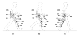
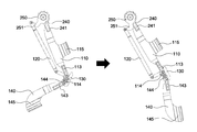
FIG. 1 is a schematic view illustrating a grounding behavior of a user wearing a leg-supporting robot to which a skeletal structure of a leg-supporting robot according to an embodiment of the present invention is applied.
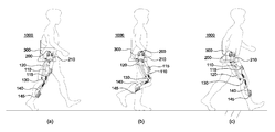
FIG. 2 is a schematic view illustrating a leg-restoring behavior of a wearer wearing a leg-resting robot to which a skeleton structure of a leg-resting robot according to an embodiment of the present invention is applied.
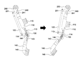
3 is an exploded view of a joint structure of a lower limb-assisted robot according to an embodiment of the present invention.
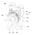
FIG. 4 shows an internal construction of a driving apparatus for controlling the driving of the joint structure of the lower limb-assisted robot according to the embodiment of the present invention.
FIG. 5 illustrates a skeleton structure of a leg-supporting robot applied to a leg supporting the user's body after contacting the ground according to an embodiment of the present invention.
FIG. 6 illustrates a skeleton structure of a leg-supporting robot applied to a leg so as to support the ground according to an embodiment of the present invention and push the ground backward to advance the user's body forward.
FIG. 7 shows a skeletal structure of a leg-resting robot applied to a leg which moves forward and crosses a user's weight center after leaving the ground.
8 shows the skeletal structure of the underarm-assisted robot applied to the legs moving forward while crossing the center of gravity of the user in a state away from the ground.
Hereinafter, preferred embodiments of the present invention will be described in detail with reference to the accompanying drawings. However, the present invention is not limited to the embodiments described herein but may be embodied in other forms. Rather, the embodiments disclosed herein are provided so that the disclosure can be thorough and complete, and will fully convey the scope of the invention to those skilled in the art. Like reference numerals designate like elements throughout the specification.
The present invention relates to a skeleton structure of a lower limb-assisted robot, and in order to facilitate understanding of the present invention, a limb-assisted robot to which the skeletal structure of the limb-assisted robot is applied will be discussed.
FIG. 1 is a perspective view of a right lower limb of a user wearing a leg-supporting robot to which a skeletal structure of a leg-supporting robot according to an embodiment of the present invention is applied. FIG. 4 is a view showing the ground motion of the right lower limb of the user wearing the lower limb robot to which the skeletal structure of the limb-supporting robot according to the present invention is applied.
The leg-resting robot shown in FIGS. 1 and 2 is mounted on the user's body through the
The
The rotational driving force provided from the
As described above, the leg-supporting
That is, the skeleton structure of the lower
The undergarment
One
3 is an exploded view of a joint structure of a lower limb-assisted robot according to an embodiment of the present invention.
1 to 3, the skeleton structure of the lower limb-assisted robot according to an embodiment of the present invention is a skeleton structure of the lower limb-assisted
The plurality of the
When the
The first and second
The first
Therefore, the first
The second
The second
The first and second
FIG. 4 shows an internal configuration diagram of a
The first and second
The first
According to an embodiment of the present invention, the driving
Only one
Accordingly, the
The
The
However, since the
Like the
The first
Here, the first and second joint driving
That is, the driving
That is, it is understood that one rotation axis hj, which is located in the
In other words, the rotation of the first and second joint driving
The
The first
The other end of the first and second
In order to precisely control the knee
The
Accordingly, each of the first and second
Here, the first and second
The
One end and the other end of the first
As described above, the knee
The
The knee
The connection structure between the knee
If the first and second
That is, if the first and second
Accordingly, the other ends of the first and second
Specifically, each of the first and second
3, the knee
The knee
The
1 to 3, the knee
In this case, the
In addition, among the vertexes of the right triangular shape, a penetration point extending in a straight downward direction from a penetration point hinged to the
Accordingly, the
The other end of the first
The
The upper knee joint 113 and the lower knee joint 143 are positioned such that the upper
The rotation of the
That is, the
As described above, according to the structure of the knee
However, either one of the first and second
For example, when the first
Since the first and second
Since the knee
If the angle at which the first
The knee
Hereinafter, according to various embodiments of the present invention, it can be seen that the skeletal structure of the leg-well sub-robot is driven in accordance with the user's walking with the leg-supporting
The walking cycle of the user can be roughly divided into a stomach (Fig. 1) and a non-stomatoscler (Fig. 2) where the lower limb is in contact with the floor, and each stomach and lean is subdivided The hips, the thighs, the knee joints, and the lower legs are individually moved to make a walk.
Therefore, the joint structure of the lower limb-assisted robot can be driven such that the user wearing the underarm-supporting
FIG. 5 illustrates a skeleton structure of a leg-supporting robot applied to a leg supporting the user's body after contacting the ground according to an embodiment of the present invention, and FIG. 6 is a cross- And the backrest is pushed back to advance the user's body forward.
Figs. 1, 5 and 6 show a state in which, after one of the legs of the user's both legs starts to come into contact with the ground (Fig. 1 (a), Fig. 5 1 (b) and 5 (b) of FIG. 1) and pushing the paper backward (FIG. 1 (c) And moves the other legs forward to show that the user's body is moving forward.
In this case, the extremity of the user in contact with the ground must support the user's body weight so that the user can move forward, and push the ground backward, and thus the user's hips must rotate in the backward direction to orient the extension.
1 and 5 to 6, the first
Here, when the first
However, the second
In other words, the second
Specifically, the
FIG. 7 shows a skeleton structure of a leg-resting robot applied to a leg which moves forward and crosses a user's body center of gravity after leaving the ground, FIG. 8 is a cross- And shows the skeletal structure of the applied lower limb robot.
Figs. 2, 7, and 8 show a state in which one of the limbs of the user's limbs begins to fall from the ground surface (Fig. 2A, Fig. 7A) (Fig. 2 (c) and Fig. 8 (b)), the body of the user moves forward.
Therefore, as shown in the drawings subsequent to FIG. 2 and FIG. 7 to FIG. 8, in the walking cycle of the user during the swinging period, the swinging legs must move forward without contacting the ground, The
Specifically, when the leg starting from the swinging leg is moved so as to intersect the base of the stance, the first and second femoral support members (110, 120) The first
In addition, it is necessary to prepare for the stance phase by rotating the stance forward when the stance that overtakes the stance during the stance phase is overturned. If the stance that advances over the stance during the stance phase advances, the lower
The first and second
As described above, the
The amount of deviation of the rotational angles of the first and second joint driving
5, when there is almost no rotational angle deviation between the first and second joint driving
7, when the rotational angular deviation of the first and second joint driving
The skeleton structure of the leg-assistance robot according to the present invention is constructed by mimicking the muscle structure of a human being. The skeleton structure of the leg-assisted robot according to the present invention is configured to connect all the joints and respective joints through a transmission path of a driving force, It is possible to minimize the volume and the weight of the underfitting
The embodiments of the present invention are not intended to limit the scope of the present invention but to limit the scope of the present invention. The scope of protection of the present invention should be construed according to the following claims, and all technical ideas within the scope of equivalents should be construed as falling within the scope of the present invention.
100: skeletal structure of lower limb robot 110: first femoral support member
120: second femoral support member 130: knee joint member
140: lower supporting member 200: driving device
240: first joint drive member 250: second joint drive member
1000: Not Assisted Robot
Claims (14)
A plurality of thigh support members each having one end connected to a drive unit of the base support robot and driven in a predetermined range;
A knee joint member connected to the other end of the plurality of the above-described thigh support members;
And a lower supporting member which is installed at one end of the knee joint member and is driven to move about the knee joint member in accordance with the movement of the plurality of the hammering support members.
The hammock support member is connected to the first hammock supporting member, which is connected to the drive unit of the underfoot assistant robot and is operable in a predetermined range, and to the drive unit of the underfoot assist robot independently from the first hammert support member And the other end includes a second thigh support member connected to the knee joint member separately from the first thigh support member and drivable in a predetermined range.
Wherein the first and second thigh support members connect the drive unit and the knee joint members in parallel.
Wherein the first thigh support member and the lower support member are configured to surround the femur and the lower limb of the wearer of the undergarment assistant robot.
The first and second joint drive members and the second joint drive member are respectively connected to the first joint drive member and the second joint drive member constituting the drive device, Wherein the first and second thigh support members are independently driven for rotation or traction driven by rotation.
Wherein the lower support member is rotated by a rotation angle deviation of the first joint drive member and the second joint drive member.
Wherein the rotation angle of the femur relative to the hip joint of the user is determined according to the rotation angle of the first joint drive member connected to the first femoral support member.
The rotation angle of the lower support member relative to the knee joint member is determined according to the rotation angle of the first joint drive member connected to the first femoral support member and the rotation angle deviation of the second joint drive member connected to the second femoral support member Wherein the first and second legs are connected to each other.
Wherein a rotation angle of the lower support member with respect to the knee joint member is increased when the rotation angle deviation is increased.
And each of the hinge shafts rotatably connecting the other end of the first and second hammock support members and the upper end of the lower support member to the knee joint member is installed so as to pass through the knee joint member in parallel The skeletal structure of the lower limb.
The piercing points of the three hinge shafts rotatably connecting the other end of the first femoral support member, the other end of the second femoral support member, and the upper end of the lower support member to the knee joint member are arranged in the shape of a triangle Features of skeletal structure of lower limb robot.
Wherein the pivot points of the three hinge shafts are arranged in a right triangle shape and the other end of the first pivot support member is connected to a vertex corresponding to a right angle among the vertexes of the right triangle.
Wherein each of the hinge shafts is connected to the hinge shafts by gears so that the other end of the first hammock support member and one end of the lower support member are rotatable about respective hinge shafts, .
And a stopper for restricting a rotation angle of the other end of the first thigh support member and a rotation angle of the lower support member to the knee joint member.
Priority Applications (1)
| Application Number | Priority Date | Filing Date | Title |
|---|---|---|---|
| KR1020150115266A KR20170021018A (en) | 2015-08-17 | 2015-08-17 | Frame Structure Of Lower Limb Assistance Robot |
Applications Claiming Priority (1)
| Application Number | Priority Date | Filing Date | Title |
|---|---|---|---|
| KR1020150115266A KR20170021018A (en) | 2015-08-17 | 2015-08-17 | Frame Structure Of Lower Limb Assistance Robot |
Related Child Applications (1)
| Application Number | Title | Priority Date | Filing Date |
|---|---|---|---|
| KR1020170078258A Division KR20170075699A (en) | 2017-06-21 | 2017-06-21 | Frame Structure Of Lower Limb Assistance Robot |
Publications (1)
| Publication Number | Publication Date |
|---|---|
| KR20170021018A true KR20170021018A (en) | 2017-02-27 |
Family
ID=58315857
Family Applications (1)
| Application Number | Title | Priority Date | Filing Date |
|---|---|---|---|
| KR1020150115266A KR20170021018A (en) | 2015-08-17 | 2015-08-17 | Frame Structure Of Lower Limb Assistance Robot |
Country Status (1)
| Country | Link |
|---|---|
| KR (1) | KR20170021018A (en) |
Cited By (8)
| Publication number | Priority date | Publication date | Assignee | Title |
|---|---|---|---|---|
| KR101862509B1 (en) * | 2017-03-23 | 2018-05-29 | 성균관대학교산학협력단 | Leg structure of walking robot |
| CN108670729A (en) * | 2018-04-27 | 2018-10-19 | 深圳市迈步机器人科技有限公司 | A kind of exoskeleton robot |
| CN109124989A (en) * | 2018-09-25 | 2019-01-04 | 深圳市丞辉威世智能科技有限公司 | Transmission device, lower limb rehabilitation ectoskeleton and exoskeleton robot |
| KR20190002953A (en) * | 2017-06-30 | 2019-01-09 | 현대로템 주식회사 | Multi link apparatus, lower-lomb exoskeleton robot using the same and methed for controlling the same |
| US10973726B2 (en) | 2017-09-04 | 2021-04-13 | Samsung Electronics Co., Ltd | Motion assistance apparatus |
| CN115847381A (en) * | 2023-02-16 | 2023-03-28 | 哈尔滨工业大学 | Configuration-changeable parallel lower limb wearing power assisting device |
| WO2023063737A1 (en) * | 2021-10-14 | 2023-04-20 | 조선대학교산학협력단 | Robot for assisting lower limbs |
| US11707399B2 (en) | 2018-12-10 | 2023-07-25 | Samsung Electronics Co., Ltd. | Motion assistance apparatus |
-
2015
- 2015-08-17 KR KR1020150115266A patent/KR20170021018A/en active Application Filing
Cited By (10)
| Publication number | Priority date | Publication date | Assignee | Title |
|---|---|---|---|---|
| KR101862509B1 (en) * | 2017-03-23 | 2018-05-29 | 성균관대학교산학협력단 | Leg structure of walking robot |
| KR20190002953A (en) * | 2017-06-30 | 2019-01-09 | 현대로템 주식회사 | Multi link apparatus, lower-lomb exoskeleton robot using the same and methed for controlling the same |
| US10973726B2 (en) | 2017-09-04 | 2021-04-13 | Samsung Electronics Co., Ltd | Motion assistance apparatus |
| CN108670729A (en) * | 2018-04-27 | 2018-10-19 | 深圳市迈步机器人科技有限公司 | A kind of exoskeleton robot |
| CN109124989A (en) * | 2018-09-25 | 2019-01-04 | 深圳市丞辉威世智能科技有限公司 | Transmission device, lower limb rehabilitation ectoskeleton and exoskeleton robot |
| CN109124989B (en) * | 2018-09-25 | 2024-03-19 | 深圳市丞辉威世智能科技有限公司 | Transmission device, lower limb rehabilitation exoskeleton and exoskeleton robot |
| US11707399B2 (en) | 2018-12-10 | 2023-07-25 | Samsung Electronics Co., Ltd. | Motion assistance apparatus |
| WO2023063737A1 (en) * | 2021-10-14 | 2023-04-20 | 조선대학교산학협력단 | Robot for assisting lower limbs |
| CN115847381A (en) * | 2023-02-16 | 2023-03-28 | 哈尔滨工业大学 | Configuration-changeable parallel lower limb wearing power assisting device |
| CN115847381B (en) * | 2023-02-16 | 2023-07-14 | 哈尔滨工业大学 | Parallel lower limb wearing booster device with changeable configuration |
Similar Documents
| Publication | Publication Date | Title |
|---|---|---|
| KR20170021018A (en) | Frame Structure Of Lower Limb Assistance Robot | |
| KR20170075699A (en) | Frame Structure Of Lower Limb Assistance Robot | |
| EP2942044B1 (en) | Forward or rearward oriented exoskeleton | |
| US10524972B2 (en) | Machine to human interfaces for communication from a lower extremity orthotic | |
| KR101219795B1 (en) | Wearable robot to assist muscular strength | |
| KR20160148074A (en) | Driving unit of multi-joint robot | |
| KR102360981B1 (en) | Leg orthosis and orthosis | |
| WO2018093448A2 (en) | Robotic upper limb rehabilitation device | |
| KR20180023708A (en) | A motion assist apparatus | |
| US10583551B2 (en) | Exoskeleton and method of increasing the flexibility of an exoskeleton joint | |
| KR20120064410A (en) | Exoskeleton apparatus for assistant physical strength | |
| JP6120421B2 (en) | Walking support machine | |
| KR101230458B1 (en) | Rehabilitation machine device for knee joint | |
| WO2019131152A1 (en) | Joint assistance unit and walking assistance device | |
| AU2014247204A1 (en) | Mechanical linkage | |
| JP6883712B2 (en) | Exoskeleton structure | |
| CN112894765A (en) | Wearable muscle strength auxiliary device | |
| KR102081911B1 (en) | Rehabilitation robot | |
| KR101390219B1 (en) | Exoskeleton | |
| KR102633470B1 (en) | Wearable Assistance Device | |
| KR102418860B1 (en) | Knee Joint Structure And Wearable Assistance Device Having The Same | |
| KR102244673B1 (en) | Driving unit of multi-joint robot | |
| CN112873177B (en) | Lower limb exoskeleton robot | |
| KR102410813B1 (en) | Wearable assisting device | |
| KR20230170447A (en) | Joint structure and exo-skeleton robot including the same |
Legal Events
| Date | Code | Title | Description |
|---|---|---|---|
| E601 | Decision to refuse application | ||
| E601 | Decision to refuse application | ||
| E801 | Decision on dismissal of amendment | ||
| A107 | Divisional application of patent |