KR20170020786A - Carrier aggregation diversity antenna module with integrated lna banks - Google Patents
Carrier aggregation diversity antenna module with integrated lna banks Download PDFInfo
- Publication number
- KR20170020786A KR20170020786A KR1020167035229A KR20167035229A KR20170020786A KR 20170020786 A KR20170020786 A KR 20170020786A KR 1020167035229 A KR1020167035229 A KR 1020167035229A KR 20167035229 A KR20167035229 A KR 20167035229A KR 20170020786 A KR20170020786 A KR 20170020786A
- Authority
- KR
- South Korea
- Prior art keywords
- diversity
- signals
- band
- downlink
- band signals
- Prior art date
Links
Images


Classifications
-
- H—ELECTRICITY
- H04—ELECTRIC COMMUNICATION TECHNIQUE
- H04W—WIRELESS COMMUNICATION NETWORKS
- H04W72/00—Local resource management
- H04W72/04—Wireless resource allocation
- H04W72/044—Wireless resource allocation based on the type of the allocated resource
- H04W72/0453—Resources in frequency domain, e.g. a carrier in FDMA
-
- H—ELECTRICITY
- H04—ELECTRIC COMMUNICATION TECHNIQUE
- H04B—TRANSMISSION
- H04B1/00—Details of transmission systems, not covered by a single one of groups H04B3/00 - H04B13/00; Details of transmission systems not characterised by the medium used for transmission
- H04B1/005—Details of transmission systems, not covered by a single one of groups H04B3/00 - H04B13/00; Details of transmission systems not characterised by the medium used for transmission adapting radio receivers, transmitters andtransceivers for operation on two or more bands, i.e. frequency ranges
- H04B1/0053—Details of transmission systems, not covered by a single one of groups H04B3/00 - H04B13/00; Details of transmission systems not characterised by the medium used for transmission adapting radio receivers, transmitters andtransceivers for operation on two or more bands, i.e. frequency ranges with common antenna for more than one band
- H04B1/0057—Details of transmission systems, not covered by a single one of groups H04B3/00 - H04B13/00; Details of transmission systems not characterised by the medium used for transmission adapting radio receivers, transmitters andtransceivers for operation on two or more bands, i.e. frequency ranges with common antenna for more than one band using diplexing or multiplexing filters for selecting the desired band
-
- H—ELECTRICITY
- H04—ELECTRIC COMMUNICATION TECHNIQUE
- H04B—TRANSMISSION
- H04B1/00—Details of transmission systems, not covered by a single one of groups H04B3/00 - H04B13/00; Details of transmission systems not characterised by the medium used for transmission
- H04B1/38—Transceivers, i.e. devices in which transmitter and receiver form a structural unit and in which at least one part is used for functions of transmitting and receiving
- H04B1/40—Circuits
- H04B1/44—Transmit/receive switching
-
- H—ELECTRICITY
- H04—ELECTRIC COMMUNICATION TECHNIQUE
- H04B—TRANSMISSION
- H04B7/00—Radio transmission systems, i.e. using radiation field
- H04B7/02—Diversity systems; Multi-antenna system, i.e. transmission or reception using multiple antennas
- H04B7/022—Site diversity; Macro-diversity
- H04B7/024—Co-operative use of antennas of several sites, e.g. in co-ordinated multipoint or co-operative multiple-input multiple-output [MIMO] systems
-
- H—ELECTRICITY
- H04—ELECTRIC COMMUNICATION TECHNIQUE
- H04J—MULTIPLEX COMMUNICATION
- H04J4/00—Combined time-division and frequency-division multiplex systems
- H04J4/005—Transmultiplexing
-
- H—ELECTRICITY
- H04—ELECTRIC COMMUNICATION TECHNIQUE
- H04L—TRANSMISSION OF DIGITAL INFORMATION, e.g. TELEGRAPHIC COMMUNICATION
- H04L1/00—Arrangements for detecting or preventing errors in the information received
- H04L1/02—Arrangements for detecting or preventing errors in the information received by diversity reception
-
- H—ELECTRICITY
- H04—ELECTRIC COMMUNICATION TECHNIQUE
- H04L—TRANSMISSION OF DIGITAL INFORMATION, e.g. TELEGRAPHIC COMMUNICATION
- H04L27/00—Modulated-carrier systems
- H04L27/26—Systems using multi-frequency codes
- H04L27/2601—Multicarrier modulation systems
Abstract
통합형 저 잡음 증폭기 뱅크들을 갖는 캐리어 어그리게이션 다이버시티 안테나 모듈이 개시된다. 예시적인 실시예에서, 장치는 적어도 하나의 다이버시티 안테나로부터 업링크 신호를 송신하기 위해 송신 신호 경로를 확립하고 적어도 하나의 다이버시티 안테나로부터 다운링크 다이버시티 신호들을 수신하기 위해 수신 신호 경로를 확립하도록 구성되는 적어도 하나의 스위치를 포함한다. 장치는 또한 적어도 3개의 다이버시티 대역 신호들을 생성하기 위해 다운링크 다이버시티 신호들을 필터링하도록 구성되는 대역 선택 필터들을 포함한다. 장치는 또한, 트랜시버로 출력되는 적어도 3개의 증폭된 다이버시티 대역 신호들을 생성하기 위해 다이버시티 대역 신호들을 증폭시키도록 구성되는 멀티플렉싱 증폭기를 포함한다.A carrier aggregation diversity antenna module with integrated low noise amplifier banks is disclosed. In an exemplary embodiment, the apparatus establishes a transmit signal path to transmit an uplink signal from at least one diversity antenna and establishes a receive signal path to receive downlink diversity signals from at least one diversity antenna And at least one switch configured. The apparatus also includes band selection filters configured to filter downlink diversity signals to produce at least three diversity band signals. The apparatus also includes a multiplexing amplifier configured to amplify the diversity band signals to produce at least three amplified diversity band signals output to the transceiver.
Description
관련 출원의 교차 참조Cross reference of related application
[0001] 본 출원은, 2014년 6월 23일에 출원된 공동 소유의 미국 가특허 출원 제62/015,951호 및 2015년 4월 1일 출원된 미국 정규 특허 출원 제14/676,639호로부터 우선권을 주장하며, 상기 출원의 내용들은 그 전체가 인용에 의해 본원에 명시적으로 포함된다.[0001] This application claims priority from commonly owned U.S. Provisional Patent Application No. 62 / 015,951, filed June 23, 2014, and U.S. Provisional Patent Application No. 14 / 676,639, filed Apr. 1, 2015, The contents of which are expressly incorporated herein by reference in their entirety.
[0002] 본 개시내용은 일반적으로 트랜시버들에 관한 것이며, 보다 구체적으로 캐리어 어그리게이션 트랜시버들에서 사용하기 위한 다이버시티 안테나 모듈에 관한 것이다.[0002] The present disclosure relates generally to transceivers, and more specifically to a diversity antenna module for use in carrier aggregation transceivers.
[0003] RF(radio frequency) 트랜시버에서, 통신 신호는 송신기에 의해 전개, 상향변환, 증폭 및 송신되고 수신기에 의해 수신, 증폭, 하향변환 및 복원된다. 수신기에서, 통신 신호가 일반적으로 수신 회로에 의해 수신되고 하향변환되어 통신 신호에 포함된 정보가 복원된다. 단일 송신기 또는 수신기는 다중 송신 주파수들 및/또는 다중 수신 주파수들을 이용하여 동작하도록 구성될 수 있다. 수신기가 2개 이상의 수신 신호들을 동시에 수신할 수 있기 위해서, 2개 이상 수신 경로들의 동시 동작이 사용된다. 그러한 시스템들은 때때로 "캐리어-어그리게이션(carrier-aggregation)"(CA) 시스템들로 지칭된다. 용어 "캐리어-어그리게이션"은, 인터-CA(inter-band carrier aggregation) 및 인트라-CA(intra-band carrier aggregation)를 포함하는 시스템들을 지칭할 수 있다. 인터-CA는 상이한 통신 대역들에서 발생하는 2개 이상의 별개의 (인접 또는 비인접) 캐리어 신호들의 프로세싱을 지칭한다. 인트라-CA는 동일한 통신 대역에서 발생하는 2개 이상의 별개의 (인접 또는 비인접) 캐리어 신호들의 프로세싱을 지칭한다. 캐리어 어그리게이팅된 RF 신호는 일반적으로, RF 신호에 존재하는 다수의 캐리어들을 프로세싱하기 위해 하나 또는 그 초과의 LNA(low noise amplifier)들을 일반적으로 사용하는 하나 또는 그 초과의 별개의 LO(local oscillator) 주파수들을 이용하여 하향변환된다. 증폭된 신호는 일반적으로, 수신된 신호에 포함된 정보를 추출하기 위해 하향변환 및 복조 회로에 의해 프로세싱된다. [0003] In a radio frequency (RF) transceiver, a communication signal is developed, upconverted, amplified and transmitted by a transmitter, received, amplified, downconverted, and recovered by a receiver. At the receiver, the communication signal is generally received by the receiving circuit and downconverted to recover the information contained in the communication signal. A single transmitter or receiver may be configured to operate using multiple transmit frequencies and / or multiple receive frequencies. The simultaneous operation of two or more receive paths is used so that the receiver can simultaneously receive two or more receive signals. Such systems are sometimes referred to as "carrier-aggregation" (CA) systems. The term "carrier-aggregation" can refer to systems that include inter-band carrier aggregation (inter-CA) and intra-band carrier aggregation (intra-CA). Inter-CA refers to the processing of two or more distinct (adjacent or non-adjacent) carrier signals occurring in different communication bands. Intra-CA refers to the processing of two or more distinct (adjacent or non-adjacent) carrier signals occurring in the same communication band. A carrier-tagged RF signal is typically one or more distinct LOs (LOs) that typically use one or more low noise amplifiers (LNAs) to process multiple carriers present in the RF signal ) ≪ / RTI > frequencies. The amplified signal is typically processed by a down-conversion and demodulation circuit to extract information contained in the received signal.
[0004] 종래의 다중-안테나 트랜시버 설계에는, 일반적으로 1차 안테나와 여러 개의 2차 안테나들이 있다. 2차 안테나들은 다이버시티 안테나들의 어레이를 구성한다. 기저대역 전자기기들(예컨대, 모뎀, 신호 컨디셔너들 등)은 송신을 위한 신호들을 생성하고 또한 수신된 신호들을 프로세싱하도록 동작한다. 기저대역 전자기기들은 RF 프런트 엔드 전자기기들에 연결되는 트랜시버와 인터페이싱한다. RF 프런트 엔드 전자기기들은 증폭기들, 듀플렉서 또는 신호들을 증폭하고 안테나로 그리고 안테나들로부터 라우팅하는 다른 필터들을 포함한다. 신호들은 다양한 통신 대역들에 있는, 이를테면, LB(low band), MB(mid band) 및/또는 HB(high band) 신호들일 수 있다.[0004] Conventional multi-antenna transceiver designs typically include a primary antenna and several secondary antennas. The secondary antennas constitute an array of diversity antennas. Baseband electronic devices (e.g., modems, signal conditioners, etc.) are operative to generate signals for transmission and to process the received signals. Baseband electronic devices interface with transceivers that are connected to RF front-end electronics. RF front end electronics include amplifiers, duplexers, or other filters that amplify signals and route them to and from the antennas. The signals may be in various communication bands, such as LB (low band), MB (mid band) and / or HB (high band) signals.
[0005] RF 프런트 엔드 전자기기들은 일반적으로, 2차 안테나들로부터 수신되는 다이버시티 신호들을 트랜시버로 라우팅하기 위한 수신기 모듈을 포함한다. 불행하게도, 종래의 수신기 모듈들은 많은 스위치들 및 필터들로 복잡해질 수 있고, 이에 큰 회로 면적을 필요로 한다. 또한, 종래의 수신기 모듈들은, 얼마나 많은 다이버시티 신호들이 동시에 수신될 수 있는지 그리고/또는 어떻게 다양한 수신 및 송신 모드들이 함께 수행되는지에 관하여 한계들을 가질 수 있다.[0005] RF front-end electronics generally include a receiver module for routing diversity signals received from secondary antennas to a transceiver. Unfortunately, conventional receiver modules can be complex with many switches and filters, requiring a large circuit area. In addition, conventional receiver modules may have limitations as to how many diversity signals can be received simultaneously and / or how various receive and transmit modes are performed together.
[0006] 따라서, 비용 및 공간 요건들을 감소시키기 위해, 사용되는 스위치들 및 필터들의 수를 감소시키거나 또는 제거하고, 그리고 종래의 설계들과 비교할 때 광범위한 송신 및 수신 결합들을 제공하는 다이버시티 수신기 모듈을 갖는 것이 바람직하다.[0006] Thus, having a diversity receiver module that reduces or eliminates the number of switches and filters used, and provides a wide range of transmit and receive combinations when compared to conventional designs, in order to reduce cost and space requirements desirable.
[0007]
도 1은 다수의 안테나들로부터 수신된 RF 신호들을 무선 시스템 내에서 통신하는 무선 디바이스의 수신기로 효율적으로 라우팅하는 다이버시티 안테나 모듈의 예시적인 실시예를 도시한다.
[0008]
도 2는 캐리어 어그리게이션 통신 시스템에서 신호 캐리어 구성들을 도시하는 다이어그램들을 도시한다.
[0009]
도 3은 다이버시티 안테나 모듈의 예시적인 실시예를 포함하는 수신기 프런트 엔드의 블록도를 도시한다.
[0010]
도 4는 도 3에 도시된 다이버시티 수신기의 상세한 예시적인 실시예를 도시한다.
[0011]
도 5는 도 3에 도시된 다이버시티 안테나 모듈의 상세한 예시적인 실시예를 도시한다.
[0012]
도 6은 도 3에 도시된 프런트 엔드와 함께 사용하기 위한 안테나 구성들을 도시한다.
[0013]
도 7은 프런트 엔드의 다이버시티 수신 신호 경로들을 도시하는 다이어그램을 도시한다.
[0014]
도 8은 다이버시티 수신기 장치의 예시적인 실시예를 도시한다.[0007] FIG. 1 illustrates an exemplary embodiment of a diversity antenna module that efficiently routes RF signals received from multiple antennas to a receiver of a wireless device that communicates within a wireless system.
[0008] FIG. 2 depicts diagrams illustrating signal carrier configurations in a carrier aggregation communication system.
[0009] FIG. 3 shows a block diagram of a receiver front end including an exemplary embodiment of a diversity antenna module.
[0010] FIG. 4 illustrates a detailed exemplary embodiment of the diversity receiver shown in FIG.
[0011] FIG. 5 shows a detailed exemplary embodiment of the diversity antenna module shown in FIG.
[0012] FIG. 6 illustrates antenna configurations for use with the front end shown in FIG.
[0013] FIG. 7 shows a diagram illustrating the diversity receive signal paths of the front end.
[0014] FIG. 8 illustrates an exemplary embodiment of a diversity receiver device.
[0015] 후술되는 상세한 설명은, 본 개시내용의 예시적인 설계들의 설명으로서 의도되며, 본 개시내용이 실시될 수 있는 유일한 설계들만을 나타내도록 의도되지 않는다. 본원에서 사용되는 용어 "예시적인"은 "예시, 실례 또는 예증의 역할을 한다"는 의미로 사용된다. "예시적인" 것으로서 본원에 설명되는 어떠한 설계도 반드시 다른 설계들보다 바람직하거나 또는 유리한 것으로 해석되어서는 안 된다. 상세한 설명은 본 개시내용의 예시적인 설계들의 완전한 이해를 제공할 목적으로 특정 세부 사항들을 포함한다. 본원에 설명된 예시적인 설계들이 이들 특정한 세부사항들 없이 실시될 수도 있다는 것은 당업자들에게 명백할 것이다. 몇몇 예시들에서, 본원에 제시된 예시적인 설계들의 신규성을 불명료하게 하는 것을 회피하기 위해, 잘 알려진 구조들 및 디바이스들은 블록도 형태로 도시되어 있다.[0015] The following detailed description is intended as a description of exemplary designs of the present disclosure and is not intended to represent only those designs in which the present disclosure may be practiced. As used herein, the term "exemplary" is used in the sense of "serving as an example, instance, or illustration. &Quot; Any design described herein as "exemplary " is not necessarily to be construed as preferred or advantageous over other designs. The detailed description includes specific details for the purpose of providing a thorough understanding of the exemplary designs of the present disclosure. It will be apparent to those skilled in the art that the exemplary designs described herein may be practiced without these specific details. In some instances, well known structures and devices are shown in block diagram form in order to avoid obscuring the novelty of the exemplary designs presented herein.
[0016]
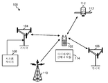
도 1은, 다수의 안테나들로부터 수신되는 RF 신호들을 무선 시스템(100) 내에서 통신하는 무선 디바이스(102)의 수신기로 효율적으로 라우팅하는 다이버시티 안테나 모듈(114)의 예시적인 실시예를 도시한다. 무선 시스템(100)은, LTE(Long Term Evolution) 시스템, CDMA(Code Division Multiple Access) 시스템, GSM(Global System for Mobile Communications) 시스템, WLAN(wireless local area network) 시스템 또는 몇몇 다른 무선 시스템일 수 있다. CDMA 시스템은 광대역 WCDMA(Wideband CDMA), CDMA 1X, EVDO(Evolution-Data Optimized), TD-SCDMA(Time Division Synchronous CDMA), 또는 CDMA의 일부 다른 버전들을 구현할 수 있다. 단순화를 위해, 도 1은 2개의 기지국들(104 및 106) 및 하나의 시스템 제어기(108)를 포함하는 무선 시스템(100)을 도시한다. 일반적으로, 무선 시스템(100)은 임의의 수의 기지국들 및 임의의 세트의 네트워크 엔티티들을 포함할 수 있다.[0016]
1 illustrates an exemplary embodiment of a
[0017]
무선 디바이스(102)는 또한, UE(user equipment), 모바일 스테이션, 단말, 액세스 단말, 가입자 유닛, 또는 스테이션으로 지칭될 수 있다. 무선 디바이스(102)는 셀룰러 폰, 스마트 폰, 태블릿, 무선 모뎀, PDA(personal digital assistant), 핸드 헬드 디바이스, 랩탑 컴퓨터, 스마트북, 넷북, 코드리스 폰, WLL(wireless local loop) 스테이션, 블루투스 디바이스 또는 다른 통신 디바이스일 수 있다. 무선 디바이스(102)는 무선 시스템(100)에서 디바이스들과 통신할 수 있다. 무선 디바이스(102)는 또한, 하나 또한 그 초과의 GNSS(global navigation satellite system)에서, 브로드캐스트 스테이션들(예컨대, 브로드캐스트 스테이션(110))로부터의 신호들, 또는 위성들(예컨대, 위성(112))로부터의 신호들을 수신할 수 있다. 무선 디바이스(102)는, LTE, WCDMA, CDMA 1X, EVDO, TD-SCDMA, GSM, 802.11과 같은 무선 통신을 위한 하나 또는 그 초과의 라디오 기술들을 지원할 수 있다. 다양한 예시적인 실시예들에서, 다이버시티 안테나 모듈(114)은 다수의 안테나들로부터 수신된 RF 신호들을 디바이스(102)의 수신기로 효율적으로 라우팅한다. 예시적인 실시예에서, 다이버시티 안테나 모듈(114)은 회로 면적을 감소시키고 기능을 증가시키기 위해서 종래의 시스템들에서 일반적으로 사용되는 스위치들 및 필터들의 수가 감소된 상태로 동작함으로써, 1차 및 다이버시티 신호들의 더 많은 조합들이 동시에 송신 및 수신될 수 있게 한다.[0017]
The
[0018]
도 2는 캐리어 어그리게이션 통신 시스템에서 신호 캐리어들을 도시하는 다이어그램들(200)을 도시한다. 예컨대, 신호 구성들은, 도 1에 도시된 통신 시스템(100)에서 송신 또는 수신될 수 있는 캐리어들을 도시한다. 예컨대, 다이어그램들(200)은, 저-대역, 중간-대역 및 고-대역 그룹들을 도시하며 각각의 대역 그룹은 하나 또는 그 초과의 캐리어 신호들을 구비할 수 있다. 다이어그램(206)에서, 저-대역 그룹은 2개의 대역들로 분리된다.[0018]
2 shows diagrams 200 illustrating signal carriers in a carrier aggregation communication system. For example, the signal constellations illustrate the carriers that may be transmitted or received in the
[0019]
다이어그램(202)은 인접 대역내(intra-band) 캐리어들의 예시를 도시한다. 예컨대, 하나의 대역에 다수의 인접 캐리어들이 있다(예컨대, 저-대역에 4개의 인접 캐리어들이 있다). 무선 디바이스(100)는 동일한 대역 내의 4개의 인접 캐리어들 상에서 송신들을 전송하고 그리고/또는 수신할 수 있다.[0019]
Diagram 202 shows an example of intra-band carriers. For example, there are a number of adjacent carriers in one band (e.g., there are four adjacent carriers in the low-band).
[0020]
다이어그램(204)은 비인접 대역내 캐리어들의 예시를 도시한다. 예컨대, 하나의 대역에 다수의 비인접 캐리어들이 있다(예컨대, 저-대역에 4개의 비인접 캐리어들이 있다). 캐리어들은 5MHZ, 10MHz 또는 다른 양으로 분리될 수 있다. 무선 디바이스(100)는 동일한 대역 내의 4개의 비인접 캐리어들 상에서 송신들을 전송하고 그리고/또는 수신할 수 있다.[0020]
Diagram 204 shows an example of carriers in non-adjacent bands. For example, there may be multiple non-adjacent carriers in a band (e.g., there are four non-adjacent carriers in the low-band). The carriers may be separated into 5 MHZ, 10 MHz or other quantities. The
[0021]
다이어그램(206)은 동일한 대역 그룹 내의 대역간 캐리어들의 예시를 도시한다. 예컨대, 2개의 대역들에 다수의 캐리어들이 존재한다(예컨대, 저-대역 1에 2개의 인접 캐리어들 및 저-대역 2에 2개의 인접 캐리어들이 존재한다). 무선 디바이스(100)는 동일한 대역 그룹 내의 상이한 대역들에서 4개의 캐리어들 상에서 송신들을 전송하고 그리고/또는 수신할 수 있다.[0021]
Diagram 206 shows an example of interband carriers in the same band group. For example, there are multiple carriers in two bands (e.g., there are two adjacent carriers in low-band 1 and two adjacent carriers in low-band 2). The
[0022]
다이어그램(208)은 상이한 대역 그룹들 내의 대역간 캐리어들의 예시를 도시한다. 예컨대, 상이한 대역 그룹들의 2개의 대역들 내에 다수의 캐리어들이 존재한다(예컨대, 저-대역 그룹에 2개의 캐리어들 및 중간-대역 그룹에 2개의 캐리어들이 존재한다). 무선 디바이스(100)는 상이한 대역 그룹들 내의 4개의 캐리어들 상에서 송신들을 전송하고 그리고/또는 수신할 수 있다. 대역들 및 대역 그룹들의 다른 조합들을 갖는 캐리어 어그리게이션 시스템 내의 다른 캐리어 구성들도 또한 지원될 수 있다는 것을 또한 주목해야 한다.[0022]
Diagram 208 shows an example of interband carriers in different band groups. For example, there are multiple carriers in two bands of different band groups (e.g., there are two carriers in the low-band group and two carriers in the mid-band group). The
[0023]
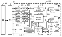
도 3은 다이버시티 안테나 모듈(114)의 예시적인 실시예를 포함하는 수신기 프런트 엔드(300)의 블록도를 도시한다. 예컨대, 수신기 프런트 엔드(300)는 도 1에 도시된 디바이스(102)에서 RF 신호들을 송신하고 수신하는데 사용하기 적합하다. 예시적인 실시예에서, BB(baseband) 프로세서(302)는 트랜시버(304)로 그리고 트랜시버(304)로부터 통신되는 기저대역 신호들을 프로세싱한다. 디바이스(102)로부터 송신되는 기저대역 신호들은 트랜시버(304)에 의해 RF 신호들로 상향변환되고 하나 또는 그 초과의 안테나들에 의한 송신을 위해 프런트 엔드(300)로 출력된다. 예컨대, RF 신호들은 도 2에 도시된 대역 그룹들 중 임의의 것에 있는 캐리어 신호들을 포함할 수 있다. 그러나, 송신을 위한 RF 신호들은 임의의 특정 대역 그룹 구성으로 제한되지 않는다. 프런트 엔드(300)에 의해 수신되는 RF 신호들은, 이 신호들이 기저대역으로 하향변환되는 트랜시버(304)로 전달된 후, 추가 프로세싱을 위해 기저대역 프로세서(302)로 전달된다.[0023]
FIG. 3 shows a block diagram of a receiver
[0024]
프런트 엔드(300)는 1차 안테나(314) 및 2차 (또는 다이버시티) 안테나들(332 및 336)을 포함하는 안테나 그룹을 이용하여 RF 신호들을 송신 및 수신한다. 필터(312)는 저-대역 크로스 스위치(310) 및 중간/고 대역 크로스 스위치(320)에 결합되며, 1차 안테나(314)와 크로스 스위치들(310 및 320) 사이에서 통신되는 신호들을 필터링한다. 예시적인 실시예에서, 필터(312)는, 1차 안테나(314)가 신호들을 저, 중간, 및 고 대역들에서 신호들을 송신하고 수신할 수 있도록 설정된다. 예컨대, 예시적인 실시예에서, 저, 중간 및 고 대역들은 도 2에 도시된 대역들이다.[0024]
The
[0025]
필터(330)는 다이버시티 안테나 모듈(114)에 결합되고 2차 안테나(332)와 다이버시티 안테나 모듈(114) 사이에서 통신되는 신호들을 필터링한다. 예시적인 실시예에서, 필터(330)는, 2차 안테나(332)가 신호들을 저, 중간, 및 고 대역들에서 신호들을 송신하고 수신할 수 있도록 설정된다. 필터(334)는 다이버시티 안테나 모듈(114)에 결합되고 2차 안테나(336)와 다이버시티 안테나 모듈(114) 사이에서 통신되는 신호들을 필터링한다. 예시적인 실시예에서, 필터(334)는, 2차 안테나(336)가 초고 대역에서 신호들을 송신하고 수신할 수 있도록 설정된다. WiFi 모뎀(338)은 2차 안테나들(332 및 336) 중 하나를 이용하여 통신한다. 예시적인 실시예에서, 모뎀(338)은, 2차 안테나(332)가 2.4GHz WiFi 대역에서 신호들을 송신하고 수신할 수 있도록, 신호들을 필터(330)로 그리고 필터(330)로부터 통신한다. 예시적인 실시예에서, 모뎀(338)은, 2차 안테나(336)가 5GHz WiFi 대역에서 신호들을 송신하고 수신할 수 있도록, 신호들을 필터(334)로 그리고 필터(334)로부터 통신한다.[0025]
The
[0026]
저 대역에서 송신될 RF 신호들이 전력 증폭기(PAL)(306)에 의해 증폭되고 듀플렉서(308)로 전달된다. 듀플렉서(308)는, 송신을 위해, 신호들을 1차 안테나(314)로 라우팅하거나 또는 다이버시티 안테나 모듈(114)을 통하여 2차 안테나(332)로 라우팅하는 저 대역 크로스 스위치(310)로 송신되도록 신호들을 전달한다. 1차 안테나(314) 또는 2차 안테나(332)로부터 수신된 저 대역 신호들은 크로스 스위치(310)로 역방향으로 동일한 경로들 중 어느 하나를 통과하여 흐른 후, 듀플렉서(308)로 입력되고 프로세싱을 위해 트랜시버(304)로 다시 전달된다.RF signals to be transmitted in the low band are amplified by a power amplifier (PA L ) 306 and transmitted to a
[0027]
중간 대역에서 송신될 RF 신호들은 PAM(316)에 의해 증폭되고 듀플렉서(318)로 전달된다. 듀플렉서(318)는, 신호들을 1차 안테나(314)로 라우팅하거나 또는 다이버시티 안테나 모듈(114)로 라우팅하는 중간/고 대역 크로스 스위치(320)로 신호들을 전달한다. 다이버시티 안테나 모듈(114)는 중간 대역 신호들을 송신을 위해 안테나(332)로 라우팅한다. 1차 안테나(314) 또는 2차 안테나(332)로부터 수신된 중간 대역 신호들은 역방향으로 다이버시티 안테나 모듈(114)을 통해 크로스 스위치(320)로 다시 흐른 후, 듀플렉서(318)로 입력되며, 이들은 필터링되고 프로세싱을 위해 트랜시버(304)로 다시 전달된다.[0027] RF signals to be transmitted in the intermediate band are amplified by the
[0028]
고 대역에서 송신될 RF 신호들은 PAH(322)에 의해 증폭되고 듀플렉서(324)로 전달된다. 듀플렉서(324)는, 신호들을 1차 안테나(314)로 라우팅하거나 또는 다이버시티 안테나 모듈(114)로 라우팅하는 중간/고 대역 크로스 스위치(320)로 신호들을 전달한다. 다이버시티 안테나 모듈(114)은 고 대역 신호들을 송신을 위해 안테나(332)로 라우팅한다. 1차 안테나(314) 또는 2차 안테나(332)로부터 수신된 고 대역 신호들은 역방향으로 다이버시티 안테나 모듈(114)을 통해 크로스 스위치(320)로 다시 흐른 후, 듀플렉서(324)로 입력되고 프로세싱을 위해 트랜시버(304)로 다시 전달된다.The RF signals to be transmitted in the high band are amplified by the
[0029]
프런트 엔드(300)는, 크로스 스위치(310)로부터 저 대역 다이버시티 신호(DL)를 수신하고 이 신호를 선택적으로 필터링하여 선택된 저 대역 다이버시티 신호들을 트랜시버(304)로 입력하는 다이버시티 수신기(DRx)(326)를 포함한다. 다이버시티 수신기(DRx)(326)는 또한 크로스 스위치(320)로부터 중간, 고 및 초고(M/H/UH) 대역 다이버시티 신호들(DM/DH/DUH)을 수신하고 이들 신호들을 선택적으로 필터링하여 선택된 중간, 고, 및 고 대역 다이버시티 신호들을 트랜시버(304)로 입력한다. The
[0030]
예시적인 실시예에서, 다이버시티 안테나 모듈(114)은 안테나(332)로부터 중간 및 고 대역 신호들을 수신하고 선택적으로 필터링하여 모듈(114)로부터 출력되고 DRx(326)로 입력되는 중간 및 고 대역 다이버시티 신호들(DMB/DHB)을 생성한다. 예시적인 실시예에서, 다이버시티 안테나 모듈(114)은 안테나(332)로부터의 고 대역 신호들을 그리고 안테나(336)로부터 초고 대역 신호들을 수신하고 선택적으로 필터링하여, 모듈(114)로부터 출력되고 DRx(326)로 입력되는 고 및 초고 대역 다이버시티 신호들(DHB/DUHB)을 생성한다. 예시적인 실시예에서, 다이버시티 안테나 모듈(114)은, 선택적인 신호 경로(340)를 이용하여 전체 또는 선택된 다이버시티 신호들을 트랜시버(304)로 직접 출력함으로써 DRx(326)를 바이패싱한다. In an exemplary embodiment, the
[0031]
DRx 모듈(326)은 크로스 스위치들(310 및 320)로부터 수신된 저, 중간, 고 및 초고 대역 다이버시티 신호들을 필터링하고 선택적으로 스위칭하여, 선택된 저, 중, 고 및 고 대역 다이버시티 신호들을 트랜시버(304)로 입력하도록 동작한다. DRx 모듈(326)은 또한 다이버시티 안테나 모듈(114)로부터 수신된 중간(DMB), 고(DHB) 및 초고(DUHB) 신호들을 선택적으로 스위칭하여 추가적인 필터링없이 이러한 신호들 중 하나 또는 그 초과의 것을 트랜시버(304)로 직접 입력하도록 동작한다.The
[0032]
다이버시티 안테나 모듈(114)은 종래의 회로들보다 더 적은 수의 컴포넌트들(예컨대, 더 적은 수의 스위치들 및 필터들)로 그리고 더 큰 유연성(예컨대, 더 많은 다이버시티 신호 조합들)을 갖는 DRx(326)를 통해 다이버시티 신호들을 효율적으로 필터링하고 트랜시버(304)로 라우팅하도록 구성된다. 예컨대, 예시적인 실시예에서, DRx 모듈(326)은 최대 4개의 다이버시티 신호들을 트랜시버(304)로 동시에 입력할 수 있다.[0032]
The
1차 안테나를 이용한 저 대역 통신들 Low-band communications using primary antennas
[0033]
프런트 엔드(300)는 저 대역에서 신호들을 송신하고 수신하는 저 대역 통신을 제공한다. 예시적인 실시예에서, 프런트 엔드(300)는 트랜시버(304)로부터 저 대역 RF 신호들을 수신하는 저 대역 전력 증폭기(PAL; low band power amplifier)(306)를 포함한다. PAL(306)은 증폭된 신호들을 듀플렉서(308)로 출력하고, 듀플렉서(308)는 신호들을 필터링하고 저 대역에서 증폭된 신호들을 저 대역 크로스 스위치(310)로 전달한다. 저 대역 크로스 스위치(310)는 필터(312)로 신호들을 출력하며, 필터(312)는 저 대역 신호들이 1차 안테나(314)에 의해 송신되기 전에 필터링을 제공한다. 1차 안테나(314)에 의해 수신된 저 대역 신호들은 필터(312)에 의해 필터링되고 저 대역 크로스 스위치(310)로 입력된다. 저 대역 크로스 스위치(310)로부터 출력된 저 대역 신호들은 듀플렉서(308)로 다시 입력되며, 이 듀플렉서(308)에서 이들 신호들이 필터링되고 트랜시버(304)로 다시 전달된다.[0033] The
2차 안테나를 이용한 저 대역 통신들Low-band communications using secondary antennas
[0034]
저 대역 크로스 스위치(310)는 또한 다이버시티 안테나 모듈(114)과 통신하여 2차 안테나(332)를 이용하여 저 대역에서 신호들을 송신하고 수신한다. 예컨대, 저 대역 크로스 스위치(310)로부터 출력된 저 대역 신호들이 저 대역 신호들을 필터(330)로 전달하는 다이버시티 안테나 모듈(114)로 입력된다. 신호들이 필터링된 후 2차 안테나(332)를 사용하여 송신된다. 2차 안테나(332)에 의해 수신된 저 대역 신호들은 필터(330)에 의해 필터링되고 다이버시티 안테나 모듈(114)로 입력된다. 다이버시티 안테나 모듈(114)은 저 대역 신호들을 크로스 스위치(310)로 출력한다. 크로스 스위치(310)로부터, 2차 안테나(332)에 의해 수신된 저 대역 신호들이 듀플렉서(308)로 입력되고 다시 트랜시버(304)로 흐른다.[0034]
The low-
저 대역 신호들의 The low- 다이버시티Diversity 수신 reception
[0035]
프런트 엔드(300)는 크로스 스위치(310)를 이용하여 저 대역 신호들의 다이버시티 수신을 수행한다. 예컨대, 1차 안테나(314) 및 2차 안테나(332) 둘 모두는 저 대역 크로스 스위치(310)로 라우팅되는 저 대역 신호들을 수신한다. 저 대역 크로스 스위치(310)는 자신의 저 대역 입력들 중 하나를 선택하여, DRx(326)로 입력되는 저 대역 다이버시티 신호(DL)로서 출력한다. DRx(326)는, 트랜시버(304)로 입력될 저 대역 다이버시티 신호의 대역들을 필터링하고 선택한다.[0035] The
1차 안테나를 이용한 중간 대역 통신들 Medium band communications using primary antennas
[0036]
프런트 엔드(300)는 중간 대역에서 신호들을 송신하고 수신하는 중간 대역 통신을 제공한다. 예시적인 실시예에서, 프런트 엔드(300)는 트랜시버(304)로부터 중간 대역 RF 신호들을 수신하는 중간 대역 전력 증폭기(PAM)(316)를 포함한다. PAM(316)은 증폭된 신호들을, 듀플렉서(318)로 출력하고, 듀플렉서(318)는 신호들을 필터링하고 중간 대역에서 증폭된 신호들을 중간/고 대역 크로스 스위치(320)로 전달한다. 크로스 스위치(320)는, 중간 대역 신호들의 신호들을 필터(312)로 출력하며, 필터(312)는 중간 대역 신호들이 1차 안테나(314)에 의해 송신되기 전에 중간 대역 필터링을 제공한다. 1차 안테나(314)에 의해 수신된 중간 대역 신호들은 필터(312)에 의해 필터링되고 크로스 스위치(320)로 입력된다. 크로스 스위치(320)로부터 출력된 중간 대역 신호들은 듀플렉서(318)로 다시 입력되며, 이 듀플렉서(318)에서 이들 신호들이 필터링되고 트랜시버(304)로 다시 전달된다.[0036] The
2차 안테나를 이용한 중간 대역 통신들Medium band communications using secondary antennas
[0037]
중간 대역 크로스 스위치(320)는 또한 다이버시티 안테나 모듈(114)과 통신하여 2차 안테나(332)를 이용하여 중간 대역에서 신호들을 송신하고 수신한다. 예컨대, 중간 대역 크로스 스위치(320)로부터 출력된 중간 대역 신호들이 다이버시티 안테나 모듈(114)로 전달되고, 필터(330)로 전달되어 2차 안테나(332)를 이용하여 송신된다. 2차 안테나(332)에 의해 수신된 중간 대역 신호들이 필터(330)에 의해 필터링되고, 다이버시티 안테나 모듈(114)로 입력된 후, 중간 대역 크로스 스위치(320)로 전달된다. 크로스 스위치(320)로부터, 2차 안테나(332)에 의해 수신된 중간 대역 신호들은 듀플렉서(318)로 입력되고 다시 트랜시버(304)로 흐른다.[0037]
The intermediate
중간 대역 신호들의 The mid- 다이버시티Diversity 수신 reception
[0038]
프런트 엔드(300)는 1차 안테나(314) 또는 2차 안테나(332)를 이용하여 중간 대역 신호들의 다이버시티 수신을 제공한다. 예컨대, 1차 안테나(314)에 의해 수신된 다이버시티 중간 대역 신호들이 필터(312)에 의해 필터링되고 크로스 스위치(320)로 입력된다. 크로스 스위치(320)로부터 출력된 다이버시티 중간 대역 신호들(DM)이 DRx(326)로 입력되고, DRx(326)에서 이들 신호들이 필터링되고 스위칭되어 트랜시버(304)로 입력되는 선택된 다이버시티 중간 대역 신호들이 생성된다.[0038] The
[0039]
다른 실시예에서, 2차 안테나(332)는 다이버시티 안테나 모듈(114)로 라우팅되는 다이버시티 중간 대역 신호들을 수신한다. 다이버시티 안테나 모듈(114)은 중간 대역들 중 하나 또는 그 초과의 것을 필터링하고 선택하여 DRx(326)로 입력되는 중간 대역 다이버시티 신호들(DMB)을 생성하며, DRx(326)는 추가 필터링없이 이러한 신호들을 트랜시버(304)로 선택적으로 입력한다.[0039] In another embodiment, the
1차 안테나를 이용한 고 대역 통신들 High-band communications using primary antennas
[0040]
프런트 엔드(300)는 고 대역에서 신호들을 송신하고 수신하는 고 대역 통신을 제공한다. 예시적인 실시예에서, 프런트 엔드(300)는 트랜시버(304)로부터 고 대역 RF 신호들을 수신하는 고 대역 전력 증폭기(PAH)(322)를 포함한다. PAH(322)는 증폭된 신호들을 듀플렉서(324)로 출력하고, 듀플렉서(324)는 신호들을 필터링하고 고 대역에서 증폭된 신호들을 크로스 스위치(320)로 전달한다. 크로스 스위치(320)는, 고 대역 신호들의 신호들을 필터(312)로 출력하며, 필터(312)는 고 대역 신호들이 1차 안테나(314)에 의해 송신되기 전에 필터링을 제공한다. 1차 안테나(314)에 의해 수신된 고 대역 신호들은 필터(312)에 의해 필터링되고 크로스 스위치(320)로 입력된다. 크로스 스위치(320)로부터 출력된 고 대역 신호들은 듀플렉서(324)로 다시 입력되며, 이 듀플렉서(324)에서 이들 신호들이 필터링되고 트랜시버(304)로 다시 전달된다.[0040] The
2차 안테나를 이용한 고 대역 통신들High-band communications using secondary antennas
[0041]
크로스 스위치(320)는 또한 다이버시티 안테나 모듈(114)과 통신하여 2차 안테나(332)를 이용하여 고 대역에서 신호들을 송신하고 수신한다. 예컨대, 크로스 스위치(320)로부터 출력된 고 대역 신호들이 다이버시티 안테나 모듈(114)로 전달되고, 필터(330)로 전달되어 2차 안테나(332)를 이용하여 송신된다. 2차 안테나(332)에 의해 수신된 고 대역 신호들은 필터(330)에 의해 필터링되고, 다이버시티 안테나 모듈(114)로 입력된 후, 크로스 스위치(320)로 전달된다. 크로스 스위치(320)로부터 고 대역 신호들이 듀플렉서(324)로 입력되고, 트랜시버(304)로 다시 흐른다.[0041]
The
고 대역 신호들의 The high- 다이버시티Diversity 수신 reception
[0042]
프런트 엔드(300)는 1차 안테나(314) 및 2차 안테나(332)를 이용하여 고 대역 신호들의 다이버시티 수신을 제공한다. 예컨대, 1차 안테나(314)에 의해 수신된 고 대역 신호들은 필터(312)에 의해 필터링되고 크로스 스위치(320)로 입력된다. 크로스 스위치(320)로부터 출력된 고 대역 신호들이 고 대역 다이버시티 신호들(DH)로서 DRx(326)로 입력되며, DRx(326)에서 이들 신호들이 트랜시버(304)로 전달되기 전에 필터링되고 스위칭된다.[0042] The
[0043]
다른 실시예에서, 2차 안테나(332)는 다이버시티 안테나 모듈(114)로 라우팅되는 고 대역 신호들을 수신한다. 다이버시티 안테나 모듈(114)은 하나 또는 그 초과의 대역들의 고 대역 다이버시티 신호들을 선택하고 선택된 고 대역 다이버시티 신호들(DHB)을 DRx(326)로 출력한다. DRx(326)는 추가적인 필터링없이 고 대역 다이버시티 신호들을 트랜시버(304)로 선택적으로 출력한다.[0043] In another embodiment, the
초고 대역 신호들의 The high- 다이버시티Diversity 수신 reception
[0044]
프런트 엔드(300)는 2차 안테나(336)와 함께 작동하는 다이버시티 안테나 모듈(114)을 이용하여 초고 대역 신호들의 송신 및 수신을 제공한다. 예컨대, 2차 안테나(336)는 다이버시티 안테나 모듈(114)로 라우팅되는 초고 대역 신호들을 수신한다. 다이버시티 안테나 모듈(114)은 하나 또는 그 초과의 대역들의 초고 대역 다이버시티 신호들을 선택하고 선택된 고 대역 다이버시티 신호들(DUHB)을 DRx(326)로 출력한다. DRx(326)는 추가적인 필터링없이 초고 대역 다이버시티 신호들을 트랜시버(304)로 출력한다.[0044] The
[0045] 다음 테이블은 FDD LTE 통신 대역들에 대한 대역 할당들, 업링크 주파수들, 다운링크 주파수들 및 대역 그룹들을 제공한다.[0045] The following table provides bandwidth assignments, uplink frequencies, downlink frequencies and band groups for FDD LTE communication bands.


[0046] 다음 테이블은 TDD LTE 통신 대역들에 대한 대역 할당들, 주파수 할당들, 대역 폭들 및 대역 그룹들을 제공한다.[0046] The following table provides bandwidth allocations, frequency allocations, bandwidths and band groups for TDD LTE communication bands.

[0047]
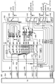
도 4는 도 3에 도시된 DRx(326)의 상세한 예시적인 실시예를 도시한다. DRx(326)는 다이버시티 신호들을 트랜시버(304)로 통신한다. 예컨대, 다이버시티 신호들은 입력 단자(404)에서 저 대역 출력(LBO) 신호, 입력 단자(406)에서 저/중간 대역 출력(LMBO) 신호, 입력 단자(408)에서 중간 대역 출력(MBO), 입력 단자(410)에서 제 1 고 대역 출력(HBO1) 신호, 입력 단자(412)에서 제 2 고 대역 출력(UHBO2), 및 입력 단자(414)에서 제 1 초고 대역 출력(UHBO1), 및 입력 단자(416)에서 제 2 초고 대역 출력(UHBO2) 신호를 포함하며, 이 신호들은 DRx(326)와 트랜시버(304) 사이에서 통신된다.[0047]
FIG. 4 shows a detailed exemplary embodiment of
[0048]
예시적인 실시예에서, DRx(326)는 도시된 바와 같이 저 대역 입력(432), 중간/고/초고 대역 입력(436), 고/초고 대역 입력(438) 및 중/고 대역 입력(440)을 수신한다. 예시적인 실시예에서, 수신된 신호들은, 스위치(442), 스위치(444) 및 스위치(446)를 포함하는 스위치 그룹(452)으로 흐른다. 스위치 그룹(452)은 수신된 신호들을 선택된 스위치 출력들로 스위칭하며, 이는, 스위칭된 신호들을 대역 통과 필터들로 전달하거나 또는 스위칭된 신호들을 직접 DRx(326)로 전달한다.[0048]
In the exemplary embodiment,
[0049]
스위치(442)는, 저 대역 입력 신호(432)를 수신하고 이 신호를 9개의 출력 단자들 중 하나로 선택적으로 연결하는 단일 입력을 포함하는 싱글 폴 9 스로우 스위치(single pole nine throw switch)를 포함한다. 스위치(442)의 제 1 출력 단자는 단자(404)에서 LBO로 직접 연결된다. 스위치(442)의 제 2 출력 단자는 멀티플렉싱 LNA(418)의 별개의 스위치로 연결되고, 그 스위치의 출력은 단자(406)에서 LMBO로 연결된다.[0049]
The
[0050]
스위치(452)의 제 3 내지 제 8 출력 단자들은, 일반적으로 454로 도시되는 필터들을 포함하는 신호 경로에 연결된다. 필터들은 저 대역 입력 신호(432)를 필터링하여 선택된 저 대역들을 멀티플렉싱 LNA(418)로 전달하도록 동작한다. 예컨대, 필터(456)는 저 대역 입력 신호(432)를 필터링하여 대역 27 "B27"을 멀티플렉싱 LNA(418)로 전달한다. 따라서, 필터들(454)은 단자(432)에서 저 대역 입력 신호를 필터링하여 대역들(B12 / B13, B26, B20, B8, B27 및 B28)을 멀티플렉싱 LNA(418)로 전달한다. 스위치(442)의 제 9 출력 단자가 임피던스 "Z"를 통해 신호 접지에 연결된다.[0050]
The third through eighth output terminals of the
[0051]
스위치(444)는, 중간/고/초고 대역 입력 신호(436)를 수신하는 제 1 입력 단자 및 스위치(446)의 출력 단자에 연결되는 제 2 입력 단자를 포함하는 더블 폴 7 스로우 스위치(double pole seven throw switch)를 포함한다. 스위치(444)의 제 1 및 제 2 입력 단자들은 출력 단자들 중 임의의 것에 연결될 수 있지만 동일한 출력 단자에는 연결되지 않는다.[0051]
The
[0052]
스위치(444)의 제 1 2개의 출력 단자들은 일반적으로 458로 도시되는 필터들에 연결된다. 필터들(458)은, 스위치(444)의 제 1 2개의 출력 단자들로부터 출력된 신호들을 필터링하여 선택된 중간 및 고 대역들을 멀티플렉싱 LNA(418)로 전달하도록 동작한다. 따라서, 필터들(458)은 스위치(444)의 제 1 2개의 출력 단자들로부터 출력된 신호들을 필터링하여 중간 대역들(B1, B3+DGSM, B25+PGSM, 및 B4) 및 고 대역들(B7 및 B30)을 멀티플렉싱 LNA(418)로 전달한다.[0052]
The first two output terminals of the
[0053]
스위치(444)는 미사용된 제 3 출력 단자 및 임피던스 "Z"를 통해 신호 접지로 연결되는 제 7 출력 단자를 포함한다. 스위치(444)의 제 3, 제 4 및 제 5 출력 단자들이 DRx(326)의 출력 단자들에 직접 연결된다. 예컨대, 제 4 출력 단자는 LMBO 단자(406)에 직접 연결되어 중간 대역(MB-B) 신호를 트랜시버(304)로 직접 전달한다. 제 5 출력 단자는 HB02 단자(412)에 직접 연결되어 고 대역(HB-B) 신호를 트랜시버(304)로 직접 전달한다. 제 6 출력 단자는 UHBO2 단자(416)에 직접 연결되어 초고 대역 신호(UHB-B)를 트랜시버(304)로 직접 전달한다. [0053]
The
[0054]
스위치(446)는 고/초고 대역 입력 신호(438) 및 중간/고 대역 입력 신호(440)를 수신하는 2개의 입력 단자들을 포함하는 더블 폴 5 스로우 스위치를 포함한다. 스위치(446)는 그의 입력 단자들에서 입력 신호들(438 및 440)을 5개의 출력 단자들 중 임의의 단자에 선택적으로 연결하여 선택된 신호들을 DRx(326)의 선택된 출력 단자들로 직접 전달한다. 예컨대, 스위치(446)의 제 1 출력 단자는 스위치(444)의 제 2 입력 단자에 연결된다. 따라서, 스위치(444)는 스위치(444)에 대한 입력으로서 단자(438)에서 HUHB 신호를 수신하거나, 단자(440)에서 MHB 신호를 수신할 수 있다. 스위치(446)의 제 2 출력 단자가 MB0 단자(408)에 직접 연결되어 중간 대역(MB-A) 신호를 트랜시버(304)로 직접 전달한다. 스위치(446)의 제 3 출력 단자가 HB02 단자(412)에 직접 연결되어 고 대역(HB-A) 신호를 트랜시버(304)로 직접 전달한다. 스위치(446)의 제 4 출력 단자가 UHBO1 단자(414) 직접 연결되어 초고 대역(UHB-A) 신호를 트랜시버(304)로 직접 전달한다. 스위치(446)의 제 6 출력 단자가 임피던스 "Z"를 통해 신호 접지에 연결된다. [0054]
[0055]
예시적인 실시예에서, MIPI(mobile industry processor interface)(448)가 스위치 그룹(452)의 스위치들(442, 444 및 446)의 동작을 제어하도록 동작한다. 예컨대, MIPI(448)가 스위치들(442, 444 및 446)의 동작을 제어하여, 디바이스에서의 다른 엔티티, 이를 테면, 기저대역 프로세서(302)로부터의 수신 커맨드 및 제어 정보에 기초하여 이 스위치들의 입력 단자들을 선택된 출력 단자들에 연결한다.[0055]
In an exemplary embodiment, a mobile industry processor interface (MIPI) 448 operates to control the operation of the
[0056]
멀티플렉싱 LNA(418)는 증폭기들(A1-A13)를 포함한다. 멀티플렉싱 LNA(418)의 선택된 증폭기들은 그들의 출력들을 함께 연결시켜 결합 신호를 생성한다. 예컨대, 증폭기들(A1-A4)의 제 1 그룹의 출력들은 그들의 출력들을 함께 연결시켜 선택된 저 대역을 포함하는 신호를 노드(420)에 제공하며, 노드(420)는 LBO 단자(404)에 연결된다. 증폭기들(A1-A10)의 제 2 그룹은 그들의 출력들을 함께 연결시켜 선택된 저 또는 중간 대역을 포함하는 신호를 노드(422)에 제공하며, 노드(422)는 LMBO 단자(406)에 연결된다. 증폭기들(A5-A10)의 제 3 그룹은 그들의 출력들을 함께 연결시켜 선택된 중간 대역을 포함하는 신호를 노드(424)에 제공하며, 노드(424)는 MBO 단자(408)에 연결된다. 증폭기들(A12-A13)의 제 4 그룹은 그들의 출력들을 함께 연결시켜 선택된 고 대역을 포함하는 신호를 노드(426)에 제공하며, 노드(426)는 HBO1 단자(410)에 연결된다. 증폭기들(A12-A13)의 제 5 그룹은 그들의 출력들을 함께 연결시켜 선택된 고 대역을 포함하는 신호를 노드(428)에 제공하며, 노드(428)는 HBO2 단자(412)에 연결된다.[0056]
The
[0057]
증폭기들(A1-A13)을 인에이블시키고 디스에이블시키는 것은 입력 신호 대역들 중 어느 것이 증폭되고 출력 노드로 전달될지를 제어한다. 예시적인 실시예에서, MIPI(430)는 멀티플렉싱 LNA(418)의 동작을 제어하기 위해 증폭기들(A1-A13)을 인에이블시키고 디스에이블시키도록 동작하여 선택된 신호 대역들을 증폭시키고 출력 단자들(404, 406, 408, 410, 및 412)로 전달한다. 따라서, DRx (326)는 1차 및 2차 안테나들 중 하나 또는 그 초과의 것으로부터 획득된 다이버시티 신호들을 수신하고, 선택된 신호들을 필터링하여 선택된 대역들로 전달하고, 선택된 대역들을 증폭하고, 증폭된 대역들을 트랜시버(304)로 입력한다. 예시적인 실시예에서, DRx(326)에 의해 수신된 선택된 다이버시티 신호들은, 스위치 그룹(452) 내의 스위치들 중 하나 또는 그 초과의 것을 통해 흐른 후 트랜시버(304)로 직접 입력된다. 예컨대, 신호들(MB-A, MB-B, HB-A, HB-B, UHB-A 및 UHB-B)이 추가적인 필터링 또는 증폭없이 스위치들(444 및 446)로부터 트랜시버(304)로 직접 흐른다.[0057]
Enabling and disabling the amplifiers A1-A13 controls which of the input signal bands are amplified and delivered to the output node. In an exemplary embodiment, the
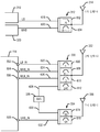
[0058]
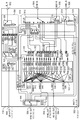
도 5는 도 3에 도시된 다이버시티 안테나 모듈(114)의 상세한 예시적인 실시예를 도시한다. 예시적인 실시예에서, 다이버시티 안테나 모듈(114)은 2차 안테나들로부터 신호들을 수신하고 트랜시버(304)로의 입력을 위해 선택된 수신 신호들을 다이버시티 신호들로서 출력한다. 예컨대, 모듈(114)은 단자(502)에서 안테나(332)로부터 저 대역 입력을, 단자(504)에서 안테나(332)로부터 중간/고 대역 입력을, 단자(506)에서 안테나(332)로부터 중간/저 대역 입력을, 그리고 단자(508)에서 안테나(336)로부터 초고 대역 입력을 수신한다. [0058]
FIG. 5 shows a detailed exemplary embodiment of the
[0059]
단자(502)에서 저 대역 입력 신호가 저 대역 모듈(530)의 스위치(520)의 입력 단자로 입력된다. 스위치(520)는 그의 입력 단자를 6개의 출력 단자들 중 하나에 연결하여 저 대역 신호를 연관된 신호 경로들로 전달한다. 필터 뱅크(560)는 스위치(520)의 출력들을 필터링하여, 선택된 저 대역 신호들을 스위치들(522 및 524)로 전달한다. 예컨대, 예시적인 실시예에서, 필터 뱅크(560)는 저 대역 입력 신호를 필터링하여 신호 대역들(B12/B13, B26, B20, B8, B29, B27 및 B28)을 모두 스위치들(522 및 524)로 전달한다.[0059]
A low-band input signal at
[0060]
필터들의 출력들이 스위치들(522 및 524)의 대응하는 입력 단자들로 흐른다. 스위치(522)는 그의 입력 단자들 중 하나를 출력 단자에 연결하여 저 대역 신호의 선택된 대역을 제 1 저 대역 입력(LB1)으로서 멀티플렉싱 LNA(532)로 전달한다. 스위치(524)는 또한 그의 입력 단자들에서 저 대역 신호의 다양한 대역들을 수신하고 그의 입력 단자 중 하나를 하나의 출력 단자에 연결하여, 선택된 저 대역 신호를 제 2 저 대역 입력(LB2)으로서 멀티플렉싱 LNA(532)로 전달한다.[0060]
The outputs of the filters flow to the corresponding input terminals of the
[0061]
스위치(526)는 크로스 스위치(310)를 이용하여 저 대역 신호들을 전송하고 수신하도록 단자(558)에 연결되는 입력 단자를 구비한다. 예컨대, 크로스 스위치(310)로부터 저 대역 송신 신호를 수신할 경우, 스위치(526)는 그의 입력 단자를 제 1 출력 단자에 연결하여 저 대역 송신 신호를 스위치(520)의 제 5 단자로 전달한다. 스위치(520)가 제 5 단자를 그의 입력 단자에 연결하도록 제어되어 저 대역 송신 신호를 단자(502)로 그리고 이에 따라 송신을 위해 안테나(332)로 전달한다. 안테나(332)로부터 저 대역 신호를 수신할 경우, 스위치(526)는 그의 입력 단자를 제 2 출력 단자에 연결하여 멀티플렉싱 LNA(532)의 노드(544)로부터 출력된 저 대역 신호 출력을 수신한다. 그런 다음, 이 신호는 단자(558)로 흐르고, 이후에는 크로스 스위치(310)로 흐른다. [0061]
The
[0062]
스위치 그룹(510)은 스위치(512) 및 스위치(514)를 포함한다. 스위치(512)는, 입력 단자에서, 단자(504)에서의 중간/고 대역 신호를 수신하고 이 입력 단자를 10개의 출력 단자들 중 하나에 선택적으로 연결한다. 스위치(512)의 출력 단자들은, 일반적으로 518로 도시되는 필터들을 포함하는 신호 경로들에 연결된다. 필터들은 단자(504)에서의 MHB 입력 신호를 필터링하여 선택된 대역들을 멀티플렉싱 LNA(532)로 전달하도록 동작한다. 예컨대, 필터들(518)은 중간/고 대역 입력 신호를 필터링하여 중간 대역들(B1, B3, B4, B25, B34 및 B39)을 멀티플렉싱 LNA(532)로 전달한다. 필터(518)는 또한 중간/고 대역 입력 신호를 필터링하여 고 대역들(B7, B30, B40A 및 B41b/B38)을 멀티플렉싱 LNA(532)로 전달한다.[0062]
The
[0063]
송신 모드 동안, 스위치(548)의 제 1 단자가 스위치(512)의 제 1 단자에 연결되어 중간/고 대역 Tx 바이패스 신호를 전달하는데, 이 스위치(548)는 중간/고 대역 Tx 바이패스 신호를 안테나(332)로 전달하기 위해 스위치(512)의 단자에 선택적으로 연결될 수 있다. 스위치(548)의 제 2 단자가 스위치들(568)의 제 1 스위치 섹션에 연결되어 중간 대역 Tx 바이패스 신호를 전달하는데, 이 중간 대역 Tx 바이패스 신호는 필터들(566)을 통과하고 스위치(512)의 제 4 단자로 흐른다. 스위치(548)의 제 5 단자가 스위치들(568)의 제 2 스위치 부분에 연결되어 고 대역 Tx 신호를 전달하는데, 이 고 대역 Tx 신호는 필터들(566)을 통과하고 스위치(512)의 제 4 단자로 흐른다. 스위치(548)의 제 7 단자가 스위치(514)의 제 2 단자에 연결되어 초고 대역 Tx 바이패스 신호를 스위치(514)로 전달한다.[0063]
During transmission mode, a first terminal of
[0064]
스위치(514)는 모듈(114)과 2차 안테나(336) 사이에서 초고 대역 신호(508)를 통신한다. 단자(508)에서 2차 안테나(336)로부터의 초고 대역 신호를 수신할 때, 스위치(514)는 그의 입력 단자를 제 1 출력 단자에 연결하여 초고 대역 신호를 필터로 전달하며, 필터는 이 신호를 필터링하여 멀티플렉싱 LNA(532)로 입력되는 초고 대역 "B42"를 출력한다. 초고 대역 신호를 송신할 경우, 스위치(514)는 그의 입력 단자를 제 2 출력 단자에 연결하여 2차 안테나(336)로 전달되는 초고 대역 송신 신호를 수신한다. MIPI(516)는 스위치 그룹(510)의 스위치들(512, 570 및 514)의 동작, 및 스위치들(568)의 동작을 제어한다.[0064]
The
[0065]
스위치(570)는 단자(506)에서의 중간/저 대역 신호를 수신하도록 연결되는 입력 단자를 갖는다. 스위치(570)는, 중간/저 대역 신호를 필터들(518)로 전달하기 위해 입력 단자에 선택적으로 연결될 수 있는 제 1 및 제 2 단자들을 구비하며, 필터들(518)은 이 신호를 필터링하여 중간 대역 신호 대역들((B11 + B21) 및 B32)을 멀티플렉싱 LNA(532)에 출력한다.[0065]
The
[0066]
멀티플렉싱 LNA(532)는 증폭기들(D1-D17)을 포함한다. 멀티플렉싱 LNA(532)의 선택된 증폭기들은 선택된 대역을 포함하는 신호를 생성하기 위해 함께 연결되는 그들의 출력들을 갖는다. 예컨대, 증폭기들(D1-D4, D7-D11 및 D13)의 제 1 그룹의 출력들은 선택된 저/중간 대역 출력(LMBO) 신호를 포함하는 신호를 제공하기 위해 노드(546)에서 함께 연결되는 그들의 출력들을 갖는다. 증폭기들(D1-D2)의 제 2 그룹은 선택된 저 대역(LBO) 신호를 제공하기 위해 노드(544)에서 함께 연결되는 그들의 출력들을 갖는다. 증폭기들(D3-D8)의 제 3 그룹은 선택된 제 1 중간/고 대역(MHBO1) 신호를 제공하기 위해 노드(542)에서 함께 연결되는 그들의 출력들을 갖는다. 증폭기들(D3-D13)의 제 4 그룹은 선택된 제 2 중간/고 대역(MHBO2) 신호를 제공하기 위해 노드(540)에서 함께 연결되는 그들의 출력들을 갖는다. 증폭기들(D5, D6, D12, D14, D15 및 D17)의 제 5 그룹은 선택된 제 1 고/초고 대역(HUHBO1) 신호를 제공하기 위해 노드(538)에서 함께 연결되는 그들의 출력들을 갖는다. 증폭기들(D5, D6, D12, D14, D15 및 D17)의 제 6 그룹은 선택된 제 2 고/초고 대역(HUHBO2) 신호를 제공하기 위해 노드(536)에서 함께 연결되는 그들의 출력들을 갖는다.[0066]
The
[0067]
증폭기들(D1-D17)을 인에이블시키고 디스에이블시키는 것은 입력 신호 대역들 중 어느 것이 증폭되고 출력 노드로 전달될지를 제어한다. 예시적인 실시예에서, MIPI(534)는, 선택된 신호 대역들을 출력하도록 멀티플렉싱 LNA(532)의 동작을 제어하기 위해 증폭기들(D1-D17)을 인에이블시키고 디스에이블시키도록 동작한다. 따라서, 다이버시티 안테나 모듈(114)은 2차 안테나들(332, 336) 중 하나 또는 그 초과의 것으로부터 획득된 다이버시티 신호들을 수신하고, 이들 신호들을 필터링하여 선택된 대역들을 전달하고, 선택된 대역들은 증폭되어 크로스 스위치(310)(예컨대, LB-out-CS)로, 크로스 스위치(320)로, 또는 트랜시버(304)로의 입력을 위해 직접 DRx(326)로 출력된다.[0067]
Enabling and disabling the amplifiers D1-D17 controls which of the input signal bands are amplified and delivered to the output node. In an exemplary embodiment, the
[0068]
도 6은 도 3에 도시된 프런트 엔드(300)와 함께, 보다 구체적으로 도 5에 도시된 다이버시티 모듈(114)과 함께 사용하기 위한 안테나 구성들을 도시한다. 1차 안테나(314)는 필터(312)와 수신 및 송신 신호들을 통신한다. 필터(312)는 저 대역 송신 및 수신 신호들을 필터링하는 제 1 스테이지(602)를 포함한다. 예컨대, 제 1 스테이지(602)는 신호 경로(618)를 사용하여 안테나(314)와 크로스 스위치(310) 사이에서 저 대역 신호들을 통신한다. 필터(312)는 중간 및 고 대역 송신 및 수신 신호들을 필터링하는 제 2 스테이지(604)를 포함한다. 예컨대, 제 2 스테이지(604)는 신호 경로를 사용하여 안테나(314)와 크로스 스위치(320) 사이에서 중간 및 고 대역 신호들을 통신한다.[0068]
FIG. 6 shows antenna configurations for use with the
[0069]
제 2 안테나(332)는 수신 및 송신 신호들을 필터(330)와 통신한다. 필터(330)는 저 대역 송신 및 수신 신호들을 필터링하는 제 1 스테이지(606)를 포함한다. 예컨대, 제 1 스테이지(606)는 단자(502)에 연결되는 신호 경로(622)를 이용하여 안테나(332)와 다이버시티 안테나 모듈(114) 사이에서 저 대역 신호들을 통신한다. 필터(330)는 고 대역 송신 및 수신 신호들을 필터링하는 제 2 스테이지(608)를 포함한다. 예컨대, 제 2 스테이지(608)는 단자(504)에 연결되는 신호 경로(624)를 이용하여 안테나(332)와 다이버시티 안테나 모듈(114) 사이에서 중간 대역 신호들을 통신한다. 필터(330)는 중간 대역 송신 및 수신 신호들을 필터링하는 제 3 스테이지(610)를 포함한다. 예컨대, 제 3 스테이지(610)는 단자(506)에 연결되는 신호 경로(626)를 이용하여 안테나(332)와 다이버시티 안테나 모듈(114) 사이에서 고 대역 신호들을 통신한다. 필터(330)는 WiFi 송신 및 수신 신호들을 필터링하는 제 4 스테이지(612)를 포함한다. 예컨대, 제 4 스테이지(612)는 신호 경로(628)를 이용하여 안테나(332)와 WiFi 모뎀(338) 사이에서 2.4GHz WiFi 신호들을 통신한다.[0069]
The
[0070]
제 2 안테나(336)는 수신 및 송신 신호들을 필터(334)와 통신한다. 필터(334)는 WiFi 송신 및 수신 신호들을 필터링하는 제 1 스테이지(614)를 포함한다. 예컨대, 제 1 스테이지(614)는 신호 경로(630)를 이용하여 안테나(336)와 WiFi 모뎀(338) 사이에서 5GHz WiFi 신호들을 통신한다. 필터(334)는 초고 대역 송신 및 수신 신호들을 필터링하는 제 2 스테이지(616)를 포함한다. 예컨대, 제 2 스테이지(616)는 단자(508)에 연결되는 신호 경로(632)를 이용하여 안테나(336)와 다이버시티 안테나 모듈(114) 사이에서 초고 대역 신호들을 통신한다.[0070]
A
[0071]
도 7은 프런트 엔드(300)의 다이버시티 수신 신호 경로들을 도시하는 다이어그램을 도시한다. 예시적인 실시예에서, 다이버시티 안테나 모듈(114)은 2차 안테나 신호들을 프로세싱하여, 트랜시버(304)로 직접 입력되는 중간, 고 및 초고 대역 다이버시티 신호들을 출력한다. 예컨대, 중간, 고 및 초고 신호들은 DRx(326)의 스위치 그룹(452)의 폐쇄 스위치들을 통해 트랜시버(304)로 흐른다.[0071]
FIG. 7 shows a diagram illustrating the diversity receive signal paths of the
[0072]
1차 안테나(314)에 의해 수신된 저 대역 신호들은 경로(618)를 따라 크로스 스위치(310)의 대역 선택기(702)로 흐른다. 2차 안테나(332)에 의해 수신된 저 대역 신호들은 저 대역 회로(530)를 통과하여 흐르고, DRx(326)의 단자(432)에서 수신되는 선택된 저 대역들(LB-in)을 출력하는 대역 선택기(702)로 출력(LB-out)된다. 크로스 스위치(310)의 대역 선택기(702)는, 그가 수신하는 저 대역들로부터 선택하여 저 대역 다이버시티 신호들(LB-in)을 DRx(326)로 출력한다.[0072]
The lowband signals received by the
[0073]
1차 안테나(314)에 의해 수신된 중간 및 고 대역 신호들은 경로(620)를 따라 크로스 스위치(320)의 대역 선택기(704)로 흐른다. 2차 안테나들 (332 및 336)에 의해 수신된 중간, 고 및 초고 대역 신호들은 경로(706)를 따라 멀티플렉싱 LNA(532)를 통해 크로스 스위치(320)의 대역 선택기(704)로 흐른다. 대역 선택기(704)는 DRx(326)의 단자(436)에서 수신되는 선택된 중간, 고, 및 초고 대역 다이버시티 신호들(MHUHB-in)을 출력한다.[0073]
The intermediate and highband signals received by the
[0074]
다이버시티 수신기(326)는 스위치 그룹(452), 대역 선택 필터들(454 및 458) 및 멀티플렉싱 LNA(418)를 포함한다. 스위치 그룹(452)은 선택된 수신 신호를, 멀티플렉싱 LNA(418)로 입력하기 위한 대역들을 선택하기 위해 신호들을 필터링하는 대역 선택 필터들(454 및 458)로 출력한다. 멀티플렉싱 LNA(418)는 신호 대역들을 결합하고 증폭하여, 트랜시버(304)로 입력되는 신호들(LBO, LMBO, MBO, HBO1 및 HBO2 신호들)을 생성한다.[0074]
The
[0075]
2차 안테나(332)에 의해 수신된 중간 및 고 대역 신호들은 다이버시티 안테나 모듈(114)의 스위치 그룹(510)으로 흐른다. 2차 안테나(336)에 의해 수신된 초고 대역 신호들은 또한 다이버시티 안테나 모듈(114)의 스위치 그룹(510)으로 흐른다. 스위치 그룹(510)은, 선택된 중간, 고 및 초고 대역 신호들을 필터들(518)로 출력하고, 필터들(518)은 수신된 신호들로부터 선택된 대역들을 필터링하고 이들 대역들을 멀티플렉싱 LNA(532)로 입력한다. 멀티플렉싱 LNA(532)는, 그가 수신하는 선택된 신호 대역들을 결합하고, 경로(706)(DM/DH/DUH)를 따라 단자(556)에서의 중/고/초고 대역 신호들(MHUHB-out)을 크로스 스위치(320)로 출력한다. 크로스 스위치(320)의 선택기(704)는 그가 수신하는 신호들로부터 선택된 중간/고/초고 대역들을 출력하며, 단자(436)에서 수신되는 MHUHB-in 신호를 DRx(326)로 출력한다.[0075] The intermediate and highband signals received by the
[0076]
멀티플렉싱 LNA(532)는 또한 단자(564)에서 고/초고 대역 다이버시티 신호(HUHB-out)를 출력하고, 단자(554)에서 중간/고 대역 다이버시티 신호들(MHB-out)을 출력한다. 이러한 신호들은 각각 단자들(438 및 440)에서 DRx(326)에 의해 수신된다. 이러한 신호들이 DRx(326)의 스위치 그룹(452)으로 입력되고, 스위치 그룹(452)은 트랜시버(304)로 직접 입력되는 이들 신호들 중 하나 또는 그 초과의 것을 선택한다. 따라서, 이러한 신호들은, 선택 필터들(454, 458)에 의해 제공되는 것과 같은 어떠한 추가적인 필터링없이 트랜시버(304)로 입력된다.[0076]
[0077]
예시적인 실시예에서, 다이버시티 안테나 모듈(114)은 종래의 시스템들과 비교할 때 더 많은 수의 다이버시티 신호 결합들을 프로세싱하도록 더 큰 유연성 및 능력을 제공한다. 예컨대, 예시적인 실시예에서, 다이버시티 안테나 모듈(114)은 다이버시티 안테나(332)를 사용하여 고 대역 TDD 신호를 송신하기 위한 송신 신호 경로를 제공하도록 구성된다. 예컨대, HB Tx 신호들이, 스위치(556)를 통과하여 HB TX 바이패스 신호 경로 상으로 스위치(568)로 흐르며, 스위치(568)는 고 대역 Tx 신호가 듀플렉서(566)로 흐를 수 있게 하도록 구성된다. 듀플렉서(566)가 MIPI(516)에 의해 스위치(504)의 입/출력 단자에 연결되도록 구성되는 스위치(512)의 제 4 단자에 연결됨으로써, 2차 안테나(332)에 의한 송신을 위해 고 대역 Tx 신호가 필터(330)로 입력된다.[0077]
In an exemplary embodiment, the
[0078]
고 대역 신호의 송신과 동시에, 2차 안테나(332)는 다이버시티 안테나 모듈(114)로 입력되는 FDD 중간 대역 및 저 대역 신호들을 수신한다. 예컨대, 저 대역 신호들이 단자(502)로 입력되고, 중간 대역 신호들이 단자들(504 및 506)로 입력된다. 수신된 저 대역 다이버시티 신호들은, 선택된 저 대역 신호들이 단자(558)로부터 출력되도록, 모듈(530)을 통해 단자(502)로부터 라우팅된다. 단자(504)에서 수신된 중간 대역 다이버시티 신호들은 듀플렉서(566)를 통해 다시 라우팅되고 대역 선택 필터들(518)로 입력된다. 예컨대, 듀플렉서(566)의 출력은. 수신된 다이버시티 신호들을 선택된 대역 선택 필터들로 출력하도록 구성되는 스위치(568)로 입력된다. 단자(506)에서 수신된 중간 대역 다이버시티 신호들은 수신된 다이버시티 신호들을 대역 선택 필터들(518)로 전달하도록 구성되는 스위치(570)로 입력된다.[0078]
At the same time as the transmission of the high-band signal, the
[0079]
대역 선택 필터(518)는 수신 다이버시티 신호들을 필터링하여, 멀티플렉싱 LNA(532)로 입력되는 중간 대역 신호들을 생성한다. 예컨대, 중간 대역 신호들은 신호 대역들(B1, B3, B4, B25, B11 + B21 및 B32)을 포함할 수 있다. 멀티플렉싱 LNA(532)는, 증폭기들(D1-D17) 중 선택된 것들을 인에이블함으로써 선택된 중간 대역 신호들을 증폭시키고 단자(554)에 연결되는 포트(540)에서 증폭된 중간 대역 신호들을 출력한다. 단자(554)는 DRx(326)의 입력 포트들(440)에 연결된다. DRx(326)의 입력 포트들(440)에서 수신된 증폭된 중간 대역 신호들이 스위치(446)에 의해 트랜시버(304)로 라우팅된다. 또한, 저 대역 다이버시티 신호들이 단자(432)에서 DRx(326)에 의해 수신되고 트랜시버(304)로 라우팅된다. 따라서, 이 예에서, 다이버시티 안테나 모듈(114)은 하나의 고 대역 TDD 신호를 송신하기 위한 송신 신호 경로를 확립하도록 구성된다. 다이버시티 안테나 모듈(114)은 또한 3개의 다운링크 FDD 다이버시티 신호들(예컨대, 1개의 저 대역 및 2개의 중간 대역 신호들)을 수신하도록 구성된다. 3개의 다운링크 다이버시티 신호들이 DRx(326)의 스위칭 기능들을 이용하여 트랜시버(304)로 입력된다. DRx(326)는 그가 수신하는 중간 대역 신호들의 추가적인 필터링을 제공하지 않으며, 따라서 이들 신호들은 추가적인 필터링없이 다이버시티 안테나 모듈(114)로부터 수신될 때 트랜시버(304)로 입력된다는 것을 주목해야 한다. 또한, 예시적인 실시예에서, 다이버시티 안테나 모듈(114)로부터 출력된 중간 대역 신호들이 도 3 및 도 7에 도시된 선택적인 신호 경로(340)를 이용하여 트랜시버(304)에 직접 입력될 수 있다는 것을 주목해야 한다.[0079]
The
[0080]
다른 예시적인 실시예에서, 다이버시티 안테나 모듈(114)은 다이버시티 안테나(332)를 이용하여 중간 대역 FDD 신호를 송신하기 위한 송신 신호 경로를 제공하도록 구성된다. 예컨대, 중간 대역 Tx 신호가, 스위치(556)를 통과하여 MB TX 바이패스 신호 경로 상으로 스위치(568)로 흐르며, 스위치(568)는 중간 대역 Tx 신호가 듀플렉서(566)로 흐를 수 있게 하도록 구성된다. 듀플렉서(566)가, 스위치(504)의 입/출력 단자에 연결될 MIPI(516)에 의해 구성되는 스위치(512)의 제 4 단자에 연결됨으로써, 2차 안테나(332)에 의한 송신을 위해 중간 대역 Tx 신호가 필터(330)로 입력된다.[0080]
In another exemplary embodiment, the
[0081]
FDD 중간 대역 신호의 송신과 동시에, 2차 안테나(332)는 다이버시티 안테나 모듈(114)로 입력되는 2개의 TDD 고 대역 신호들 및 FDD 저 및 중간 대역 신호들을 수신한다. 예컨대, 저 대역 신호들이 단자(502)로 입력되고, 고 및 중간 대역 신호들이 단자들(504 및 506)로 입력된다. 수신된 저 대역 다이버시티 신호들은 모듈(530)을 통해 단자(502)로부터 라우팅되어, 선택된 저 대역 신호들이 단자(558)로부터 출력된다. 단자(504)에서 수신된 중간 및 고 대역 다이버시티 신호들은 듀플렉서(566)를 통해 다시 라우팅되고 대역 선택 필터들(518)로 입력된다. 예컨대, 듀플렉서(566)의 출력은 수신된 다이버시티 신호들을 선택된 대역 선택 필터들로 출력하도록 구성되는 스위치(568)로 입력된다. 단자(506)에서 수신된 중간 대역 다이버시티 신호들은 수신된 다이버시티 신호들을 대역 선택 필터들(518)로 전달하도록 구성되는 스위치(570)로 입력된다.[0081]
Simultaneously with the transmission of the FDD intermediate band signal, the
[0082]
대역 선택 필터(518)는 수신 다이버시티 신호들을 필터링하여, 멀티플렉싱 LNA(532)로 입력되는 고 및 중간 대역 신호들을 생성한다. 예컨대, 중간 대역 신호들은 신호 대역들(B1, B3, B4, B25, B11 + B21 및 B32)을 포함할 수 있고 고 대역 신호들은 (B7, B30)을 포함할 수 있다. 멀티플렉싱 LNA(532)는, 증폭기들(D1-D17) 중 선택된 것들을 인에이블함으로써 선택된 중간 대역 신호들을 증폭하고 단자들(554 및 564)에 연결되는 포트들(540) 및 포트(538)에서, 증폭된 고 및 중간 대역 신호들을 출력한다. 단자(554)가 DRx(326)의 입력 포트들(440)에 연결되고, 단자(564)가 DRx(326)의 단자(438)에 연결된다. DRx(326)의 입력 포트들(440)에서 수신된 증폭된 중간 대역 신호들은 스위치(446)에 의해 트랜시버(304)로 라우팅된다. 입력 포트(438)에서 수신되는 증폭된 고 대역 신호들은 또한 스위치(446)에 의해 트랜시버(304)로 라우팅된다. 이외에도, 저 대역 다이버시티 신호들은 단자(432)에서 DRx(326)에 의해 수신되고 트랜시버(304)로 라우팅된다. 따라서, 이 예에서, 다이버시티 안테나 모듈(114)은 하나의 중간 대역 FDD 신호를 송신하기 위한 송신 신호 경로를 확립하도록 구성된다. 다이버시티 안테나 모듈(114)은 또한 4개의 다운링크 FDD 다이버시티 신호들(예컨대, 1개의 저 대역 및 2개의 고 대역(인트라 CA), 1개의 중간 신호들)을 수신하도록 구성된다. 4개의 다운링크 다이버시티 신호들은 DRx(326)의 스위칭 기능들을 이용하여 트랜시버(304)로 입력된다. DRx(326)는, 그가 수신하는 고 및 중간 대역 신호들의 추가적인 필터링을 제공하지 않으며, 따라서 이들 신호들은 추가적인 필터링없이 다이버시티 안테나 모듈(114)로부터 수신될 때 트랜시버(304)로 입력된다는 것을 주목해야 한다. 또한, 예시적인 실시예에서, 다이버시티 안테나 모듈(114)로부터 출력된 고 및 중간 대역 신호들이 도 3 및 도 7에 도시된 선택적인 신호 경로(340)를 이용하여 트랜시버(304)로 직접 입력될 수 있다는 것을 주목해야 한다.[0082]
The
[0083]
따라서, 다이버시티 안테나(332)에 의해 수신된 저 대역 다이버시티 신호들은 단자(432)에서 DRx(326)로 입력되고 트랜시버(304)에 선택적으로 입력될 수 있다. 저 대역 다이버시티 신호들을 수신하는 것 이외에, 다이버시티 안테나 모듈(114)은 안테나들(332 및 336)로부터 중간, 고 및 초고 대역 다이버시티 신호들을 동시에 수신한다. 그런다음, 다이버시티 안테나 모듈(114)의 멀티플렉싱 LNA(532)는 크로스 스위치(320)에, 선택된 중간, 고 및 초고 대역 신호를 (단자(556)에서) 출력하고, 선택된 중간, 고 및 초고 신호 대역들을 DRx(326)로 (단자들(564, 554)에서) 출력한다. DRx(326)는, 단자들(432, 436, 438, 및 440)에서 수신된 신호 대역들로부터 선택하여 트랜시버(304)로 입력할 저, 중간, 고 및 초고 대역 다이버시티 신호들을 결정할 수 있다.[0083]
The low band diversity signals received by the
[0084]
또한, 예시적인 실시예에서, 멀티플렉싱 LNA(532)로부터 출력된 중간, 고 및 초고 신호 대역들이 DRx(326)로 직접 입력되고 스위치 그룹(452)에서 수신된다. 스위치 그룹(452)은 추가적인 필터링없이 어느 신호가 트랜시버(304)에 직접 입력될 것인지를 결정하기 위해 이러한 수신된 신호들로부터 선택을 한다. 따라서, 트랜시버(304)는 동시에 최대 4개의 다이버시티 신호들을 수신하는 것이 가능하다. 예컨대, 트랜시버(304)는 1차 안테나(314)로부터 저 대역 다이버시티 신호를 수신하고 2차 안테나들(332 및 336)로부터 3개의 추가 다이버시티 신호들을 수신할 수 있다. 예컨대, 3개의 추가 다이버시티 신호들은 중간, 고 및 초고 대역들로부터 선택될 수 있다. 따라서, 트랜시버(304)에 의해 동시에 수신될 수 있는 다이버시티 신호들의 대역 그룹 조합들은 (L/M/M/H, L/M/H/H, L/M/H/UH, L/L/M/H, L/L/M/UH, M/M/H/H, 및 M/M/UH/UH)을 포함한다. 또한, 다른 대역 그룹 조합들이 가능하며 도면들에 도시된 다양한 모듈들 및 스위치들의 스위치 선택들로부터 결정될 수 있음을 주목해야 한다.[0084]
Further, in the exemplary embodiment, the intermediate, high, and ultra high signal bands output from the
[0085]
따라서, 다이버시티 안테나 모듈(114)은 2차 안테나들(332 및 336)로부터 수신된 다이버시티 신호들을 프로세싱하고 선택된 다이버시티 신호들을 다이버시티 수신기(326)로 직접 제공하고 그리고/또는 크로스 스위치들(310, 320)로 제공한다. DRx(326)로 제공된 다이버시티 신호들은 추가적인 증폭 및/또는 필터링없이 트랜시버(304)로 직접 입력된다. 예시적인 실시예에서, 신호들은 스위치 그룹(452)의 폐쇄 스위치들을 통해 흐르지만 추가적인 필터링이 방지된다. 예시적인 실시예에서, 선택 신호 경로(340)는 다이버시티 신호들을 트랜시버(304)에 직접 입력하는데 사용될 수 있다. 다양한 실시예들은 종래의 프런트 엔드들에 비해 부품들, 공간 및 비용들을 감소시키면서 더 많은 유연성 및 다이버시티 신호 수신 결합들을 제공한다.[0085]
The
[0086]
도 8은 다이버시티 수신기 장치(800)의 예시적인 실시예를 도시한다. 예시적인 실시예에서, 장치(800)는 도 5에 도시된 다이버시티 수신기 모듈(114)로서 사용하기에 적합하다.[0086]
FIG. 8 illustrates an exemplary embodiment of a
[0087]
장치(800)는, 적어도 하나의 다이버시티 안테나로부터 업링크 신호를 송신하기 위해 송신 신호 경로를 확립하도록 구성되고 적어도 하나의 다이버시티 안테나로부터 다운링크 다이버시티 신호들을 수신하기 위해 수신 신호 경로를 확립하도록 구성되는, 스위칭하기 위한 제 1 수단(802)을 포함하며, 이는 예시적인 실시예에서, 스위치 그룹(510)을 포함한다. 장치(800)는 또한, 적어도 3개의 다이버시티 대역 신호들을 생성하기 위해 다운링크 다이버시티 신호들을 필터링하도록 구성되는, 대역 선택을 위한 제 2 수단(804)을 포함하며, 이는 예시적인 실시예에서, 필터들(518)을 포함한다. 장치(800)는 또한, 트랜시버로 출력되는 적어도 3개의 증폭된 다이버시티 대역 신호들을 생성하기 위해 다이버시티 대역 신호들을 증폭시키도록 구성되는, 증폭하기 위한 제 3 수단(806)을 포함하며, 이는 예시적인 실시예에서, 멀티플렉싱 LNA(532)를 포함한다.[0087]
The
[0088] 본원에 설명된 예시적인 실시예들은 IC, 아날로그 IC, RFIC, 혼합-신호 IC, ASIC, PCB(printed circuit board), 전자 디바이스 등에서 구현될 수 있다. 예시적인 실시예들은 또한 다양한 IC 프로세스 기술들, 이를 테면, CMOS(complementary metal oxide semiconductor), NMOS(N-channel MOS), PMOS(P-channel MOS), BJT(bipolar junction transistor), BiCMOS(bipolar-CMOS), SiGe(silicon germanium), GaAs(gallium arsenide), HBT(heterojunction bipolar transistor)들, HEMT(high electron mobility transistor)들, SOI(silicon-on-insulator) 등으로 제조될 수 있다.[0088] The exemplary embodiments described herein may be implemented in ICs, analog ICs, RFICs, mixed-signal ICs, ASICs, printed circuit boards (PCBs), electronic devices, Exemplary embodiments also include various IC process technologies, such as complementary metal oxide semiconductor (CMOS), n-channel MOS (NMOS), p-channel MOS (PMOS), bipolar junction transistor (BJT), bipolar- CMOS), silicon germanium (SiGe), gallium arsenide (GaAs), heterojunction bipolar transistors (HBT), high electron mobility transistors (HEMT), and silicon-on-insulator (SOI).
[0089] 본원에 설명된 예시적인 실시예를 구현하는 장치는 독립형 디바이스일 수 있거나 대형 디바이스의 일부일 수 있다. 디바이스는 (i) 독립형 IC, (ⅱ) 데이터 및/또는 명령들을 저장하기 위한 메모리 IC들을 포함할 수 있는 하나 또는 그 초과의 IC들의 세트, (ⅲ) RFIC, 이를 테면, RF 수신기(RFR) 또는 RTR(RF transmitter/receiver), (ⅳ) ASIC, 이를 테면, MSM(mobile station modem), (v) 다른 디바이스들 내에 임베딩될 수 있는 모듈, (ⅵ) 수신기, 셀룰러 폰, 무선 디바이스, 핸드셋, 또는 모바일 유닛, (ⅶ) 등일 수 있다.[0089] An apparatus embodying the exemplary embodiments described herein may be a stand-alone device or may be part of a larger device. A device may be a set of one or more ICs that may include (i) a standalone IC, (ii) memory ICs for storing data and / or instructions, (iii) an RFIC, such as an RF receiver RTR (RF transmitter / receiver), (iv) ASIC, such as a mobile station modem (MSM), (v) a module that can be embedded in other devices, (vi) a receiver, a cellular phone, a wireless device, A mobile unit, or the like.
[0090] 본 개시내용의 이전 설명은 어떤 당업자라도 본 개시내용을 사용 또는 실시할 수 있게 하도록 제공된다. 본 개시내용에 대한 다양한 변형들은 당업자들에게 용이하게 명백할 것이며, 본원에 정의된 일반적인 원리들은 본 개시내용의 범위를 벗어나지 않으면서 다른 변경들에 적용될 수 있다. 따라서, 본 개시내용은 본원에 설명된 예들 및 설계들로 제한되도록 의도되지 않으며, 본 개시내용은 본원에 개시된 원리들 및 신규한 특징들과 일치하는 가장 넓은 범위를 따를 것이다.[0090] The previous description of the disclosure is provided to enable any person skilled in the art to make or use the disclosure. Various modifications to the present disclosure will be readily apparent to those skilled in the art, and the generic principles defined herein may be applied to other modifications without departing from the scope of the present disclosure. Accordingly, the present disclosure is not intended to be limited to the examples and designs described herein, and this disclosure will be accorded the widest scope consistent with the principles and novel features disclosed herein.
Claims (20)
적어도 하나의 다이버시티 안테나로부터 업링크 신호를 송신하기 위해 송신 신호 경로를 확립하고 상기 적어도 하나의 다이버시티 안테나로부터 다운링크 다이버시티 신호들을 수신하기 위해 수신 신호 경로를 확립하도록 구성되는 적어도 하나의 스위치;
적어도 3개의 다이버시티 대역 신호들을 생성하기 위해 상기 다운링크 다이버시티 신호들을 필터링하도록 구성되는 대역 선택 필터들; 및
트랜시버로 출력되는 적어도 3개의 증폭된 다이버시티 대역 신호들을 생성하기 위해 상기 다이버시티 대역 신호들을 증폭시키도록 구성되는 멀티플렉싱 증폭기를 포함하는, 장치.As an apparatus,
At least one switch configured to establish a transmit signal path for transmitting an uplink signal from at least one diversity antenna and establish a receive signal path for receiving downlink diversity signals from the at least one diversity antenna;
Band selection filters configured to filter the downlink diversity signals to generate at least three diversity band signals; And
And a multiplexing amplifier configured to amplify the diversity band signals to produce at least three amplified diversity band signals output to the transceiver.
상기 송신 신호 경로는 업링크 TDD(time division duplex) 신호를 송신하도록 구성되고, 상기 대역 선택 필터들은 적어도 3개의 다운링크 FDD(frequency division duplex) 다이버시티 대역 신호들을 생성하기 위해, 수신된 다운링크 다이버시티 신호들을 필터링하도록 구성되는, 장치.The method according to claim 1,
Wherein the transmit signal path is configured to transmit an uplink time division duplex (TDD) signal and the band selection filters are configured to transmit at least three downlink frequency division duplex (FDD) Lt; RTI ID = 0.0 > signals. ≪ / RTI >
상기 업링크 TDD 신호는 고 대역 그룹에 존재하고, 상기 적어도 3개의 다운링크 FDD 다이버시티 대역 신호들은 저 및 중간 대역 그룹들 중 적어도 하나에 존재하는, 장치. 3. The method of claim 2,
Wherein the uplink TDD signal is in a highband group and the at least three downlink FDD diversity band signals are present in at least one of low and middle band groups.
상기 멀티플렉싱 증폭기는 상기 적어도 3개의 다운링크 FDD 다이버시티 대역 신호들의 증폭된 버전들을 생성하기 위해 상기 적어도 3개의 다운링크 FDD 다이버시티 대역 신호들을 증폭시키고, 상기 중간 대역 그룹 내에 있는 상기 적어도 3개의 다운링크 FDD 다이버시티 대역 신호들의 상기 증폭된 버전들은 상기 트랜시버로 출력되는, 장치.The method of claim 3,
Wherein the multiplexing amplifier amplifies the at least three downlink FDD diversity band signals to generate amplified versions of the at least three downlink FDD diversity band signals, and wherein the at least three downlink And the amplified versions of the FDD diversity band signals are output to the transceiver.
상기 송신 신호 경로는 업링크 FDD 신호를 송신하도록 구성되고, 상기 대역 선택 필터들은 4개의 다운링크 다이버시티 대역 신호들을 생성하기 위해, 수신된 다이버시티 신호들을 필터링하도록 구성되는, 장치. The method according to claim 1,
Wherein the transmit signal path is configured to transmit an uplink FDD signal and the band selection filters are configured to filter received diversity signals to produce four downlink diversity band signals.
상기 업링크 FDD 신호는 중간 대역 그룹에 존재하며, 제 1 및 제 2 다운링크 다이버시티 대역 신호들은 상기 고 대역에 존재하는 TDD 신호들을 포함하고, 그리고 제 3 및 제 4 다운링크 다이버시티 대역 신호들은 저 및 중간 대역들 중 적어도 하나에 존재하는 FDD 신호들을 포함하는, 장치. 6. The method of claim 5,
Wherein the uplink FDD signal is in a middle band group and the first and second downlink diversity band signals comprise TDD signals present in the high band and the third and fourth downlink diversity band signals are And FDD signals present in at least one of the low and middle bands.
상기 멀티플렉싱 증폭기는 상기 4개의 다운링크 다이버시티 대역 신호들의 증폭된 버전들을 생성하기 위해 상기 4개의 다운링크 다이버시티 대역 신호들을 증폭시키고, 상기 고 대역 및 상기 중간 대역 내에 있는 상기 4개의 다운링크 다이버시티 대역 신호들의 상기 증폭된 버전들은 상기 트랜시버로 출력되는, 장치.The method according to claim 6,
Wherein the multiplexing amplifier is configured to amplify the four downlink diversity band signals to produce amplified versions of the four downlink diversity band signals and to amplify the four downlink diversity signals in the high band and the middle band, And the amplified versions of the band signals are output to the transceiver.
상기 멀티플렉싱 증폭기는, 증폭된 다이버시티 대역 신호들을 생성하기 위해 상기 다이버시티 대역 신호들을 수신하고 상기 다이버시티 대역 신호들을 선택적으로 증폭시키는 복수의 증폭기들을 포함하고, 각각의 증폭기는 상기 멀티플렉싱 증폭기로부터 출력된 증폭된 다이버시티 대역 신호의 주파수 대역에 기초하여 상기 멀티플렉싱 증폭기의 출력 포트에 연결되는 출력을 갖는, 장치.The method according to claim 1,
Wherein the multiplexing amplifier comprises a plurality of amplifiers for selectively receiving the diversity band signals and for amplifying the diversity band signals to generate amplified diversity band signals, And an output coupled to an output port of the multiplexing amplifier based on a frequency band of the amplified diversity band signal.
상기 출력 포트들은 중간 및 고 대역들에 있는 증폭된 다이버시티 대역 신호들을 출력하는 제 1 출력 포트, 중간 및 고 대역들에 있는 증폭된 다이버시티 대역 신호들의 제 2 부분을 출력하는 제 2 출력 포트, 고 및 초고 대역들에 있는 증폭된 다이버시티 대역 신호들의 제 3 부분을 출력하는 제 3 출력 포트, 및 고 및 초고 대역들에 있는 증폭된 다이버시티 대역 신호들의 제 4 부분을 출력하는 제 4 포트를 포함하는, 장치.9. The method of claim 8,
The output ports include a first output port for outputting amplified diversity band signals in the middle and high bands, a second output port for outputting a second portion of the amplified diversity band signals in the middle and high bands, A third output port for outputting a third portion of the amplified diversity band signals in the high and ultra high bands and a fourth port for outputting a fourth portion of the amplified diversity band signals in the high and ultra high bands, Comprising:
상기 제 1 출력 포트, 상기 제 2 출력 포트, 상기 제 3 출력 포트 및 상기 제 4 출력 포트 중 적어도 하나는 상기 트랜시버에 직접 연결되는, 장치.10. The method of claim 9,
Wherein at least one of the first output port, the second output port, the third output port, and the fourth output port is directly connected to the transceiver.
상기 제 1 출력 포트, 상기 제 2 출력 포트, 상기 제 3 출력 포트 및 상기 제 4 출력 포트 중 적어도 하나는 선택된 증폭된 다이버시티 대역 신호들을 상기 트랜시버로 출력하는 적어도 하나의 중간 컴포넌트에 연결되는, 장치.10. The method of claim 9,
Wherein at least one of the first output port, the second output port, the third output port, and the fourth output port is coupled to at least one intermediate component that outputs selected amplified diversity band signals to the transceiver, .
상기 수신된 다이버시티 신호들을 상기 대역 선택 필터들 중 하나 또는 그 초과의 것에 선택적으로 출력하도록 상기 적어도 하나의 스위치를 제어하도록 구성되는 제 1 제어기를 더 포함하는, 장치.The method according to claim 1,
Further comprising a first controller configured to control the at least one switch to selectively output the received diversity signals to one or more of the band selection filters.
상기 제 1 출력 포트, 상기 제 2 출력 포트, 상기 제 3 출력 포트 및 상기 제 4 출력 포트로부터, 선택된 증폭된 다이버시티 대역 신호들을 출력하도록 상기 멀티플렉싱 증폭기를 제어하도록 구성되는 제어기를 더 포함하는, 장치.9. The method of claim 8,
Further comprising a controller configured to control the multiplexing amplifier to output selected amplified diversity band signals from the first output port, the second output port, the third output port, and the fourth output port, .
상기 장치는 무선 디바이스의 프런트 엔드에서, 상기 증폭기 다이버시티 대역 신호들을 상기 트랜시버로 라우팅하도록 구성되는, 장치.The method according to claim 1,
Wherein the apparatus is configured to route the amplifier diversity band signals to the transceiver at a front end of the wireless device.
적어도 하나의 다이버시티 안테나로부터 업링크 신호를 송신하기 위해 송신 신호 경로를 확립하도록 구성되고 상기 적어도 하나의 다이버시티 안테나로부터 다운링크 다이버시티 신호들을 수신하기 위해 수신 신호 경로를 확립하도록 구성되는, 스위칭하기 위한 수단;
적어도 3개의 다이버시티 대역 신호들을 생성하기 위해 상기 다운링크 다이버시티 신호들을 필터링하도록 구성되는, 대역 선택을 위한 수단; 및
트랜시버로 출력되는 적어도 3개의 증폭된 다이버시티 대역 신호들을 생성하기 위해 상기 다이버시티 대역 신호들을 증폭시키도록 구성되는, 증폭하기 위한 수단을 포함하는, 장치.As an apparatus,
And configured to establish a transmit signal path for transmitting an uplink signal from at least one diversity antenna and to establish a receive signal path for receiving downlink diversity signals from the at least one diversity antenna, Means for;
Means for band selection configured to filter the downlink diversity signals to produce at least three diversity band signals; And
And amplify the diversity band signals to produce at least three amplified diversity band signals output to the transceiver.
상기 송신 신호 경로는 상기 적어도 하나의 다이버시티 안테나로부터 업링크 TDD(time division duplex) 신호를 송신하도록 구성되고, 상기 대역 선택을 위한 수단은 상기 증폭하기 위한 수단으로 입력되는 적어도 3개의 다운링크 FDD(frequency division duplex) 다이버시티 대역 신호들을 생성하기 위해 상기 다운링크 다이버시티 신호들을 필터링하도록 구성되는, 장치. 16. The method of claim 15,
Wherein the transmit signal path is configured to transmit an uplink time division duplex (TDD) signal from the at least one diversity antenna and the means for band selection comprises at least three downlink FDDs frequency division duplex (FDD) diversity band signals.
상기 업링크 TDD 신호는 고 대역 그룹에 존재하고, 상기 적어도 3개의 다운링크 FDD 다이버시티 대역 신호들은 저 및 중간 대역 그룹들 중 적어도 하나에 존재하는, 장치.17. The method of claim 16,
Wherein the uplink TDD signal is in a highband group and the at least three downlink FDD diversity band signals are present in at least one of low and middle band groups.
상기 증폭하기 위한 수단은 상기 적어도 3개의 다운링크 FDD 다이버시티 대역 신호들의 증폭된 버전들을 생성하기 위해 상기 적어도 3개의 다운링크 FDD 다이버시티 대역 신호들을 증폭하고, 상기 중간 대역 그룹 내의 상기 증폭된 다이버시티 대역 신호들은 상기 트랜시버로 출력되는, 장치.18. The method of claim 17,
Wherein the means for amplifying comprises means for amplifying the at least three downlink FDD diversity band signals to produce amplified versions of the at least three downlink FDD diversity band signals and for amplifying the amplified diversity Band signals are output to the transceiver.
상기 송신 신호 경로는 중간 대역 업링크 FDD 신호를 상기 적어도 하나의 다이버시티 안테나로 송신하도록 구성되고 상기 대역 선택을 위한 수단은 고 대역에 존재하는 TDD 신호들을 포함하는 제 1 및 제 2 다운링크 다이버시티 대역 신호들을 생성하기 위해 상기 다운링크 다이버시티 신호들을 필터링하도록 구성되고, 제 3 및 제 4 다운링크 다이버시티 대역 신호들은 저 및 중간 대역들 중 적어도 하나에 존재하는 FDD 신호들을 포함하는, 장치.16. The method of claim 15,
Wherein the transmit signal path is configured to transmit an intermediate band uplink FDD signal to the at least one diversity antenna and wherein the means for band selection comprises first and second downlink diversity < RTI ID = 0.0 > Wherein the third and fourth downlink diversity band signals are configured to filter the downlink diversity signals to produce band signals, wherein the third and fourth downlink diversity band signals comprise FDD signals present in at least one of the low and middle bands.
상기 증폭하기 위한 수단은 4개의 다운링크 다이버시티 대역 신호들의 증폭된 버전들을 생성하기 위해 상기 4개의 다운링크 다이버시티 대역 신호들을 증폭하고, 상기 고 대역 및 상기 중간 대역 내에 있는 상기 4개의 다운링크 다이버시티 대역 신호들의 상기 증폭된 버전들은 상기 트랜시버로 출력되는, 장치.20. The method of claim 19,
Wherein the means for amplifying comprises means for amplifying the four downlink diversity band signals to produce amplified versions of four downlink diversity band signals and for amplifying the four downlink diversity signals within the high band and the middle band, And the amplified versions of the band-band signals are output to the transceiver.
Applications Claiming Priority (5)
| Application Number | Priority Date | Filing Date | Title |
|---|---|---|---|
| US201462015951P | 2014-06-23 | 2014-06-23 | |
| US62/015,951 | 2014-06-23 | ||
| US14/676,639 | 2015-04-01 | ||
| US14/676,639 US10390343B2 (en) | 2014-06-23 | 2015-04-01 | Carrier aggregation diversity antenna module with integrated LNA banks |
| PCT/US2015/035252 WO2015199990A1 (en) | 2014-06-23 | 2015-06-11 | Carrier aggregation diversity antenna module with integrated lna banks |
Publications (1)
| Publication Number | Publication Date |
|---|---|
| KR20170020786A true KR20170020786A (en) | 2017-02-24 |
Family
ID=54870979
Family Applications (1)
| Application Number | Title | Priority Date | Filing Date |
|---|---|---|---|
| KR1020167035229A KR20170020786A (en) | 2014-06-23 | 2015-06-11 | Carrier aggregation diversity antenna module with integrated lna banks |
Country Status (7)
| Country | Link |
|---|---|
| US (1) | US10390343B2 (en) |
| EP (1) | EP3158650A1 (en) |
| JP (1) | JP6622230B2 (en) |
| KR (1) | KR20170020786A (en) |
| CN (1) | CN106471744B (en) |
| BR (1) | BR112016030053A2 (en) |
| WO (1) | WO2015199990A1 (en) |
Cited By (1)
| Publication number | Priority date | Publication date | Assignee | Title |
|---|---|---|---|---|
| US11159147B2 (en) | 2019-04-10 | 2021-10-26 | Samsung Electro-Mechanics Co., Ltd. | Front end module |
Families Citing this family (26)
| Publication number | Priority date | Publication date | Assignee | Title |
|---|---|---|---|---|
| US9774485B2 (en) | 2014-05-16 | 2017-09-26 | Qualcomm Incorporated | Multiplex modules for carrier aggregation receivers |
| US9813137B2 (en) * | 2014-10-31 | 2017-11-07 | Skyworks Solutions, Inc. | Diversity receiver front end system with flexible routing |
| US9853698B2 (en) * | 2015-04-29 | 2017-12-26 | Qorvo Us, Inc. | CA FDD-FDD and FDD-TDD architecture |
| US9608692B2 (en) | 2015-06-11 | 2017-03-28 | At&T Intellectual Property I, L.P. | Repeater and methods for use therewith |
| US10142086B2 (en) * | 2015-06-11 | 2018-11-27 | At&T Intellectual Property I, L.P. | Repeater and methods for use therewith |
| US9912027B2 (en) | 2015-07-23 | 2018-03-06 | At&T Intellectual Property I, L.P. | Method and apparatus for exchanging communication signals |
| US10616053B2 (en) | 2015-12-04 | 2020-04-07 | Skyworks Solutions, Inc. | Multi-stage reconfigurable triplexer |
| KR102496907B1 (en) * | 2016-06-16 | 2023-02-08 | 삼성전자주식회사 | Antenna and Electric Device comprising the same |
| US9961600B2 (en) * | 2016-06-30 | 2018-05-01 | Qualcomm Incorporated | Techniques for employing antenna switched diversity in wireless communications |
| CN115664484A (en) * | 2016-08-11 | 2023-01-31 | 中兴通讯股份有限公司 | Method, device and medium for acquiring and informing packet indication information |
| US10811767B2 (en) | 2016-10-21 | 2020-10-20 | At&T Intellectual Property I, L.P. | System and dielectric antenna with convex dielectric radome |
| KR102559978B1 (en) * | 2017-02-21 | 2023-07-26 | 삼성전자 주식회사 | Front end module supporting device to device communication using a plurality of frequency bands and electronic device comprising the front end module |
| JP6729790B2 (en) * | 2017-03-14 | 2020-07-22 | 株式会社村田製作所 | High frequency module |
| CN107124190B (en) * | 2017-05-10 | 2021-05-25 | Oppo广东移动通信有限公司 | Radio frequency circuit switch chip, radio frequency circuit, antenna device and electronic equipment |
| CN107104698B (en) * | 2017-05-10 | 2021-03-02 | Oppo广东移动通信有限公司 | Radio frequency circuit switch chip, radio frequency circuit, antenna device and electronic equipment |
| US20190097671A1 (en) * | 2017-09-26 | 2019-03-28 | Apple Inc. | Converged transmitter architecture with reduced power consumption |
| CN108039892B (en) * | 2017-12-04 | 2020-11-13 | Tcl移动通信科技(宁波)有限公司 | Mobile terminal for expanding LTE B42 frequency band bandwidth and implementation method thereof |
| US10541716B1 (en) * | 2018-09-28 | 2020-01-21 | Apple Inc. | Radio frequency front-end circuitry amplifier gain calibration systems and methods |
| CN110808722A (en) * | 2019-10-08 | 2020-02-18 | 珠海众通乐行网络科技有限公司 | Circuit for improving LTE diversity sensitivity |
| US20210211145A1 (en) * | 2020-01-08 | 2021-07-08 | Skyworks Solutions, Inc. | Ultrahigh band architecture for radio frequency front-ends |
| CN113746496B (en) * | 2020-03-03 | 2022-07-08 | Oppo广东移动通信有限公司 | Radio frequency system and electronic equipment |
| US11394432B2 (en) * | 2020-06-26 | 2022-07-19 | Avago Technologies International Sales Pte. Limited | Front end module (FEM) with integrated functionality |
| DE112021003812T5 (en) | 2020-07-16 | 2023-04-27 | Murata Manufacturing Co., Ltd. | High frequency circuit and communication device |
| JP2022019182A (en) | 2020-07-17 | 2022-01-27 | 株式会社村田製作所 | High frequency module and communication device |
| US11967981B2 (en) * | 2021-10-01 | 2024-04-23 | Skyworks Solutions, Inc. | Diversity receiver product architectures for high band, ultra-high band and E-UTRAN new radio |
| CN113949400B (en) * | 2021-11-30 | 2022-12-13 | Oppo广东移动通信有限公司 | Radio frequency system and communication equipment |
Family Cites Families (28)
| Publication number | Priority date | Publication date | Assignee | Title |
|---|---|---|---|---|
| KR20020072539A (en) | 2000-09-29 | 2002-09-16 | 가부시키가이샤 엔.티.티.도코모 | High-sensitivity wireless receiving device and high-frequency unit used therefor |
| US7116952B2 (en) | 2003-10-09 | 2006-10-03 | Intel Corporation | Method and apparatus to provide an area efficient antenna diversity receiver |
| US7869528B2 (en) | 2003-10-31 | 2011-01-11 | Northrop Grumman Systems Corporation | Multi-carrier transceiver assembly |
| JP2006135814A (en) | 2004-11-08 | 2006-05-25 | Fujitsu Ltd | Wireless receiver |
| KR100654459B1 (en) | 2005-06-30 | 2006-12-06 | 삼성전자주식회사 | Low noise amplifier for wideband and method for amplifying rf signal using the amplifier |
| US20120032782A1 (en) * | 2006-12-27 | 2012-02-09 | Colella Brian A | System for restricted biometric access for a secure global online and electronic environment |
| US20090108911A1 (en) | 2007-10-30 | 2009-04-30 | Rohm Co., Ltd. | Analog switch |
| KR101454487B1 (en) | 2008-01-04 | 2014-11-03 | 엘지전자 주식회사 | Tuner |
| EP2293458B1 (en) * | 2008-06-25 | 2015-09-02 | Hitachi Metals, Ltd. | High-frequency circuit, high-frequency component, and communication device |
| US8086197B2 (en) | 2008-11-12 | 2011-12-27 | Nxp B.V. | Multi-channel receiver architecture and reception method |
| US8045592B2 (en) | 2009-03-04 | 2011-10-25 | Laird Technologies, Inc. | Multiple antenna multiplexers, demultiplexers and antenna assemblies |
| US8976302B2 (en) | 2009-09-30 | 2015-03-10 | Wi-Lan, Inc. | Radio frequency front end for television band receiver and spectrum sensor |
| JP2011130088A (en) | 2009-12-16 | 2011-06-30 | Sony Corp | User equipment, method for performing handover, base station, and radio communication system |
| US8837331B2 (en) | 2011-02-02 | 2014-09-16 | Qualcomm Incorporated | Duplexer bypass |
| EP2487800B1 (en) | 2011-02-11 | 2013-06-19 | Alcatel Lucent | Active antenna arrays |
| US9252827B2 (en) | 2011-06-27 | 2016-02-02 | Qualcomm Incorporated | Signal splitting carrier aggregation receiver architecture |
| US20130043946A1 (en) * | 2011-08-16 | 2013-02-21 | Qualcomm Incorporated | Low noise amplifiers with combined outputs |
| US9219594B2 (en) * | 2012-06-18 | 2015-12-22 | Rf Micro Devices, Inc. | Dual antenna integrated carrier aggregation front end solution |
| US9312888B2 (en) | 2012-06-29 | 2016-04-12 | Qualcomm Incorporated | Antenna interface circuits for carrier aggregation on multiple antennas |
| US9300420B2 (en) | 2012-09-11 | 2016-03-29 | Qualcomm Incorporated | Carrier aggregation receiver architecture |
| US8774068B2 (en) | 2012-10-11 | 2014-07-08 | Sony Corporation | Dual swapping switches to meet linearity demands of carrier aggregation |
| US9543903B2 (en) | 2012-10-22 | 2017-01-10 | Qualcomm Incorporated | Amplifiers with noise splitting |
| EP3031140B1 (en) | 2013-08-08 | 2019-04-17 | Telefonaktiebolaget LM Ericsson (publ) | Low noise amplifier module and method of implementation |
| CN103780280B (en) | 2014-02-27 | 2016-06-15 | 华为技术有限公司 | Radio frequency path |
| US9374042B2 (en) * | 2014-03-27 | 2016-06-21 | Infineon Technologies Ag | System and method for a low noise amplifier |
| US9654169B2 (en) * | 2014-04-22 | 2017-05-16 | Skyworks Solutions, Inc. | Apparatus and methods for multi-band radio frequency signal routing |
| US9774485B2 (en) | 2014-05-16 | 2017-09-26 | Qualcomm Incorporated | Multiplex modules for carrier aggregation receivers |
| US9473336B2 (en) | 2014-05-16 | 2016-10-18 | Qualcomm Incorporated | Radio frequency (RF) front end having multiple low noise amplifier modules |
-
2015
- 2015-04-01 US US14/676,639 patent/US10390343B2/en not_active Expired - Fee Related
- 2015-06-11 WO PCT/US2015/035252 patent/WO2015199990A1/en active Application Filing
- 2015-06-11 BR BR112016030053A patent/BR112016030053A2/en not_active Application Discontinuation
- 2015-06-11 KR KR1020167035229A patent/KR20170020786A/en not_active Application Discontinuation
- 2015-06-11 CN CN201580033608.7A patent/CN106471744B/en not_active Expired - Fee Related
- 2015-06-11 JP JP2016574390A patent/JP6622230B2/en active Active
- 2015-06-11 EP EP15731452.7A patent/EP3158650A1/en not_active Withdrawn
Cited By (1)
| Publication number | Priority date | Publication date | Assignee | Title |
|---|---|---|---|---|
| US11159147B2 (en) | 2019-04-10 | 2021-10-26 | Samsung Electro-Mechanics Co., Ltd. | Front end module |
Also Published As
| Publication number | Publication date |
|---|---|
| CN106471744B (en) | 2020-10-23 |
| JP2017527155A (en) | 2017-09-14 |
| JP6622230B2 (en) | 2019-12-18 |
| US10390343B2 (en) | 2019-08-20 |
| US20150373711A1 (en) | 2015-12-24 |
| WO2015199990A1 (en) | 2015-12-30 |
| BR112016030053A2 (en) | 2017-08-22 |
| EP3158650A1 (en) | 2017-04-26 |
| CN106471744A (en) | 2017-03-01 |
Similar Documents
| Publication | Publication Date | Title |
|---|---|---|
| CN106471744B (en) | Carrier aggregation diversity antenna module with integrated LNA bank | |
| US10439858B2 (en) | Multiplex modules for carrier aggregation receivers | |
| JP6224293B1 (en) | Two-stage low noise amplifier for multiband receivers | |
| US9154171B2 (en) | Reconfigurable radio frequency circuits and methods of receiving | |
| US10848105B2 (en) | Power amplification module | |
| KR101804529B1 (en) | Radio frequency (rf) front end having multiple low noise amplifier modules | |
| US9419674B2 (en) | Shared filter for transmit and receive paths | |
| CN108141258B (en) | Analog processing system for massive MIMO | |
| EP3149859A1 (en) | Reconfigurable multi-mode transceiver | |
| JP2017539151A (en) | SAW-less architecture for receivers | |
| KR20210131874A (en) | Radio frequency circuit and communication device | |
| WO2016118375A1 (en) | Half-duplex sawless receiver | |
| US20090085671A1 (en) | Load inductor sharing |
Legal Events
| Date | Code | Title | Description |
|---|---|---|---|
| A201 | Request for examination | ||
| E601 | Decision to refuse application |