KR20170019614A - Device for Electrolyte Injection Including Vacuum Generator and Battery Cell Prepared by Using the Same - Google Patents
Device for Electrolyte Injection Including Vacuum Generator and Battery Cell Prepared by Using the Same Download PDFInfo
- Publication number
- KR20170019614A KR20170019614A KR1020150113650A KR20150113650A KR20170019614A KR 20170019614 A KR20170019614 A KR 20170019614A KR 1020150113650 A KR1020150113650 A KR 1020150113650A KR 20150113650 A KR20150113650 A KR 20150113650A KR 20170019614 A KR20170019614 A KR 20170019614A
- Authority
- KR
- South Korea
- Prior art keywords
- electrolyte
- battery case
- vacuum generator
- electrolytic solution
- electrolyte solution
- Prior art date
Links
Images


Classifications
-
- H01M2/361—
-
- H—ELECTRICITY
- H01—ELECTRIC ELEMENTS
- H01M—PROCESSES OR MEANS, e.g. BATTERIES, FOR THE DIRECT CONVERSION OF CHEMICAL ENERGY INTO ELECTRICAL ENERGY
- H01M10/00—Secondary cells; Manufacture thereof
- H01M10/42—Methods or arrangements for servicing or maintenance of secondary cells or secondary half-cells
- H01M10/4214—Arrangements for moving electrodes or electrolyte
-
- H01M2/0287—
-
- Y—GENERAL TAGGING OF NEW TECHNOLOGICAL DEVELOPMENTS; GENERAL TAGGING OF CROSS-SECTIONAL TECHNOLOGIES SPANNING OVER SEVERAL SECTIONS OF THE IPC; TECHNICAL SUBJECTS COVERED BY FORMER USPC CROSS-REFERENCE ART COLLECTIONS [XRACs] AND DIGESTS
- Y02—TECHNOLOGIES OR APPLICATIONS FOR MITIGATION OR ADAPTATION AGAINST CLIMATE CHANGE
- Y02E—REDUCTION OF GREENHOUSE GAS [GHG] EMISSIONS, RELATED TO ENERGY GENERATION, TRANSMISSION OR DISTRIBUTION
- Y02E60/00—Enabling technologies; Technologies with a potential or indirect contribution to GHG emissions mitigation
- Y02E60/10—Energy storage using batteries
-
- Y02E60/12—
Landscapes
- Engineering & Computer Science (AREA)
- Manufacturing & Machinery (AREA)
- Chemical & Material Sciences (AREA)
- Chemical Kinetics & Catalysis (AREA)
- Electrochemistry (AREA)
- General Chemical & Material Sciences (AREA)
- Filling, Topping-Up Batteries (AREA)
- Secondary Cells (AREA)
Abstract
Description
본 발명은 진공 생성기를 포함하는 전해액 주액 장치 및 이를 사용하여 제조된 전지셀에 관한 것이다.The present invention relates to an electrolyte injection apparatus including a vacuum generator and a battery cell manufactured using the same.
모바일 기기에 대한 기술 개발과 수요의 증가로, 이차전지의 수요 또한 급격히 증가하고 있으며, 그 중에서도 에너지 밀도와 작동전압이 높고 보존과 수명 특성이 우수한 리튬 이차전지는 각종 모바일 기기는 물론 다양한 전자제품의 에너지원으로 널리 사용되고 있다.Due to the development of technology and demand for mobile devices, the demand for secondary batteries is also rapidly increasing. Among them, lithium secondary batteries, which have high energy density, high operating voltage and excellent storage and life characteristics, It is widely used as an energy source.
리튬 이차전지는 집전체 상에 각각 활물질이 도포되어 있는 양극과 음극 사이에 다공성의 분리막이 개재된 전극조립체에 리튬염을 포함하는 전해액이 함침되어 있는 구조로 이루어져 있다. 양극 활물질은 주로 리튬 코발트계 산화물, 리튬 망간계 산화물, 리튬 니켈계 산화물, 리튬 복합 산화물 등으로 이루어져 있으며, 음극 활물질은 주로 탄소계 물질로 이루어져 있다. 충전 시에는 양극 활물질의 리튬 이온이 방출되어 음극의 탄소층으로 삽입되고, 방전시에는 반대로 음극 탄소층의 리튬 이온이 방출되어 양극 활물질로 삽입되며, 이때 전해액은 음극과 양극 사이에서 리튬 이온을 이동시키는 매질 역할을 한다. The lithium secondary battery has a structure in which an electrolyte solution containing a lithium salt is impregnated in an electrode assembly having a porous separator interposed between a positive electrode and a negative electrode coated with an active material on a current collector. The cathode active material is mainly composed of a lithium cobalt oxide, a lithium manganese oxide, a lithium nickel oxide, a lithium composite oxide and the like, and the anode active material is mainly composed of a carbon-based material. During charging, lithium ions of the positive electrode active material are released and inserted into the carbon layer of the negative electrode. In discharging, lithium ions of the negative electrode carbon layer are released and inserted into the positive electrode active material. At this time, the electrolyte moves lithium ions between the negative electrode and the positive electrode It acts as a medium to make.
따라서, 상기와 같은 전극조립체들을 포함하는 이차전지가 고용량 및 고에너지 밀도를 갖고 긴 수명을 유지하기 위해서는 전지 내부에 개재된 전극조립체가 전해액에 완전히 함침되어 전극들 간의 전극반응이 활발히 일어날 수 있도록 하여야 하며, 전극조립체가 전해액에 불완전하게 함침되는 경우에는 전극간의 반응이 원활하지 못하여 저항이 높아지고 출력 특성 및 전지의 용량이 급격히 떨어지며, 이로 인하여 전지 성능 저하, 수명 단축 현상 등이 나타나는 것은 물론, 높은 저항의 발현으로 전지의 열화 또는 폭발 현상이 일어날 수 있는 위험에 노출되게 된다.Therefore, in order for the secondary battery including the above-mentioned electrode assemblies to have a high capacity and a high energy density and to maintain a long lifetime, the electrode assembly disposed inside the battery is completely impregnated with the electrolyte solution so that the electrode reaction between the electrodes can be actively performed When the electrode assembly is impregnated incompletely in the electrolyte solution, the reaction between the electrodes is not smooth, the resistance is increased, the output characteristics and the capacity of the battery are drastically lowered, thereby deteriorating the battery performance, shortening the life span, The battery is exposed to the risk of deterioration or explosion of the battery.
상기 전해액은 리튬 이차전지 제조의 마지막 단계에서 전지 내로 투입되는데, 일반적으로 전해액은 전해질 염을 효과적으로 용해시키고 해리시킬 수 있는 극성을 가진 극성 용매임과 동시에, 활성수소를 갖고 있지 않은 비양자성 용매이다. 이러한 전해액은 종종 전해액 내부의 광범위한 상호작용으로 인해 점성 및 표면장력이 높은 바, 고밀도로 적층되어 있거나 또는 적층 상태로 권취되어 있는 전극조립체에 침투시키기 어렵고, 따라서, 전해액을 함침시키기까지 긴 시간을 필요로 한다.The electrolyte solution is introduced into the battery at the final stage of the production of the lithium secondary battery. In general, the electrolyte solution is a polar solvent having a polarity capable of effectively dissolving and dissociating the electrolyte salt, and is an aprotic solvent having no active hydrogen. These electrolytic solutions often have a high viscosity and surface tension due to extensive interactions within the electrolyte and are difficult to penetrate into an electrode assembly that is laminated at high density or wound in a laminated state and therefore requires a long time to impregnate the electrolyte .
따라서, 이차전지의 성능을 개선하고 안전성을 향상시키기 위하여 전극조립체의 전해액 함침성을 높이기 위한 여러 방법에 대한 연구가 계속적으로 진행되고 왔다.Therefore, in order to improve the performance of the secondary battery and improve safety, various methods for increasing the electrolyte impregnability of the electrode assembly have been continuously studied.
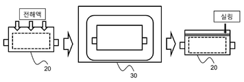
도 1에는 종래의 진공 챔버 안에서 전해액을 함침하는 공정에 대한 과정이 도시되어 있다.FIG. 1 illustrates a process for impregnating an electrolyte in a conventional vacuum chamber.
도 1을 참조하면, 과정 (a)에서 전극조립체(도시하지 않음)가 내장된 전지케이스(20)에 전해액을 주액하고, 과정 (b)에서 전해액이 주액된 전지케이스(20)를 진공 챔버(30) 내부로 이동 시킨다. 진공 챔버(30) 내부로 이동된 전지케이스(20)는 진공 상태에서 전극조립체 내의 포어(pore) 내부의 기체가 제거되고 전해액이 전극조립체 내로 깊숙이 함침되도록 유도된다. 과정 (c)에서는 진공 챔버(30)로부터 나온 전지케이스(20)의 외주면을 실링하여 전지셀 제조 공정을 완료한다.1, an electrolytic solution is injected into a
그러나, 이러한 종래의 주액 방법은 전지셀이 전해액이 주액된 상태에서 진공 챔버로 이동하기 때문에, 전극 내의 포어 내부의 기체가 완전히 제거되지 않으므로, 전해액이 전극 내로 함침되는데 한계가 있다.However, such a conventional liquid pouring method has a limitation in that the gas in the pores in the electrode is not completely removed since the battery cell moves to the vacuum chamber in the state where the electrolyte solution is poured therein, so that the electrolyte solution is impregnated into the electrode.
따라서, 전지셀 제조 공정에서 전해액 함침성을 향상시킬 수 있는 기술에 대한 필요성이 높은 실정이다.Therefore, there is a high need for a technique capable of improving electrolyte impregnability in a battery cell manufacturing process.
본 발명은 상기와 같은 종래기술의 문제점과 과거로부터 요청되어온 기술적 과제를 해결하는 것을 목적으로 한다.SUMMARY OF THE INVENTION It is an object of the present invention to solve the above-mentioned problems of the prior art and the technical problems required from the past.
구체적으로, 본 발명의 목적은 전지셀 제조 공정에서 전극조립체 내에 전해액을 주액하는 과정에서 전극 내부의 기체를 완전히 제거하여 전해액이 전극 내로 깊숙이 함침되도록 유도할 수 있는 전해액 주액 장치를 제공하는 것이다.In particular, it is an object of the present invention to provide an electrolyte solution injecting apparatus capable of completely removing gas inside an electrode during a process of injecting an electrolyte solution into an electrode assembly in a battery cell manufacturing process to induce the electrolyte solution to be impregnated deeply into the electrode.
이러한 목적을 달성하기 위한 본 발명에 따른 전해액 주액 장치는,According to an aspect of the present invention,
전지셀의 제조 공정에서 전극조립체가 수납부에 내장되어 있는 전지케이스에 전해액을 주입하는 장치로서,An apparatus for injecting an electrolyte into a battery case in which an electrode assembly is housed in a housing part in a manufacturing process of the battery cell,
전지케이스의 일변에 장착되는 전해액 주액기; 및An electrolyte main liquor mounted on one side of the battery case; And
전지케이스의 일변에서 상기 전해액 주액기로부터 이격된 위치에 장착되는 진공 생성기;A vacuum generator mounted on a side of the battery case at a position spaced apart from the electrolyte main liquor;
를 포함할 수 있고,, ≪ / RTI >
상기 전해액 주액 장치는, 상기 진공 생성기에 의해 수납부를 진공으로 만든 후 전해액 주입기에 의해 전해액을 수납부에 주입하도록 작동하는 구조일 수 있다.The electrolyte solution injecting apparatus may have a structure in which the accommodating section is made to be vacuumed by the vacuum generator, and then the electrolytic solution injector injects the electrolytic solution into the accommodating section.
따라서, 본 발명에 따른 전해액 주액 장치는, 진공 생성기에 의해 수납부를 진공으로 만듦으로써 전극 내의 기체를 완전히 제거할 수 있고, 전해액 주입기에 의해 기체가 제거된 전극 내에 전해액을 주입함으로써, 전해액이 전극 내로 깊숙이 함침되도록 유도할 수 있다.Therefore, the electrolyte injection device according to the present invention can completely remove the gas in the electrode by making the accommodating portion vacuum by the vacuum generator, and by injecting the electrolytic solution into the electrode from which the gas is removed by the electrolyte injector, It can be induced to be deeply impregnated.
상기 전극조립체는 스택형 또는 스택/폴딩형 구조로 이루어져 있을 수 있다.The electrode assembly may have a stacked or stacked / folded structure.
상기 전지케이스는 금속층과 수지층을 포함하는 라미네이트 구조의 파우치형 케이스일 수 있다.The battery case may be a pouch type case having a laminate structure including a metal layer and a resin layer.
상기 전지케이스의 하나의 구체적인 예로서, 상기 전지케이스는 우수한 내구성의 수지 외층, 차단성의 금속층, 및 열용융성의 수지 실란트층을 포함하는 라미네이트 시트로 이루어져 있고, 상기 수지 실란트층이 상호 열융착되는 것일 수 있다.As a specific example of the battery case, the battery case is made of a laminate sheet including a resin outer layer of excellent durability, a metal layer of barrier property, and a heat-fusible resin sealant layer, and the resin sealant layers are heat- .
상기 수지 외층은 외부 환경으로부터 우수한 내성을 가져야 하므로, 소정 이상의 인장강도와 내후성을 가지는 것이 필요하다. 그러한 측면에서 외측 수지층의 고분자 수지로는 폴리에틸렌 테레프탈레이트(PET)와 연신 나일론 필름이 바람직하게 사용될 수 있다.Since the resin outer layer must have excellent resistance from the external environment, it is necessary to have a tensile strength and weather resistance higher than a predetermined level. In this respect, polyethylene terephthalate (PET) and stretched nylon film can be preferably used as the polymer resin of the outer resin layer.
상기 차단성 금속층은 가스, 습기 등 이물질의 유입 내지 누출을 방지하는 기능 이외에 전지케이스의 강도를 향상시키는 기능을 발휘할 수 있도록, 바람직하게는 알루미늄이 사용될 수 있다.The barrier metal layer may preferably be made of aluminum so as to exhibit a function of improving the strength of the battery case, in addition to a function of preventing foreign matter such as gas or moisture from leaking or leaking.
상기 수지 실란트층은 열융착성(열접착성)을 가지고, 전해액의 침입을 억제하기 위해 흡습성이 낮으며, 전해액에 의해 팽창하거나 침식되지 않는 폴리올레핀(polyolefin)계 수지가 바람직하게 사용될 수 있으며, 더욱 바람직하게는 무연신 폴리프로필렌(CPP)이 사용될 수 있다.The resin sealant layer may preferably be a polyolefin resin having low heat absorbability (thermal adhesiveness), low hygroscopicity to suppress penetration of an electrolyte solution, and not being swollen or eroded by an electrolytic solution, Preferably, lead-free polypropylene (CPP) can be used.
상기 전지케이스의 외주는 전해액 주액기와 진공 생성기가 장착된 부위를 제외하고 열융착 되어 실링(sealing)되어 있을 수 있다. 이는 수납부에서 전해액 주액기 및 진공 생성기로 연통된 부위를 제외하고 완전히 밀봉하여, 진공 생성기에 의해 수납부 내부를 완전히 진공 상태로 만들기 위함일 수 있다.The outer circumference of the battery case may be thermally fused and sealed except for a portion where the electrolyte liquid main body and the vacuum generator are mounted. This can be done to completely seal the inside of the storage portion except for the portion communicated with the electrolyte main liquor and the vacuum generator and to make the inside of the storage portion completely vacuumed by the vacuum generator.
전해액 주입기의 하나의 구체적인 예로서, 상기 전해액 주입기는,As one specific example of the electrolyte injector,
전해액 주액 장치의 외부로부터 전해액이 유입되고, 하기 전해액 저장부의 상부에 연통되어 있는 전해액 유입부;An electrolyte inflow portion into which an electrolytic solution flows from the outside of the electrolyte solution instilling device and communicates with an upper portion of the electrolytic solution storing portion;
상기 전해액 유입부로부터 유입된 전해액을 저장하고, 하부가 하기 전해액 주입부에 연통되어 있는 전해액 저장부; 및An electrolytic solution storage part for storing the electrolytic solution introduced from the electrolytic solution inflow part and communicating with the lower electrolytic solution injection part at the lower part; And
상기 전지케이스의 일변을 관통하여 장착되고, 상기 전해액 저장부로부터 유입된 전해액을 상기 수납부로 주액하는 전해액 주입부;An electrolyte injecting unit mounted through one side of the battery case and injecting the electrolytic solution introduced from the electrolyte storage unit into the accommodating unit;
를 포함하는 구조로 이루어져 있을 수 있다.As shown in FIG.
또한, 상기 전해액 유입부 및 전해액 저장부의 연통 부위에는 제 1 밸브가 장착되어 있을 수 있고, 상기 전해액 저장부 및 전해액 주입부의 연통 부위에는 제 3 밸브가 장착되어 있을 수 있다.In addition, a first valve may be mounted on the communicating portion of the electrolyte inflow portion and the electrolyte reservoir, and a third valve may be mounted on the communicating portion of the electrolyte reservoir and the electrolyte infusion portion.
상기와 같은 구조에 의해, 본 발명에 따른 전해액 주액 장치는,According to the above structure, in the electrolyte solution injecting apparatus according to the present invention,
상기 제 1 밸브가 제 3 밸브가 폐쇄된 상태에서 개방되어, 전해액 유입부로부터 전해액 저장부로 전해액이 유입될 수 있고, 유입된 전해액이 전해액 저장부로 저장될 수 있다.The first valve is opened in a state where the third valve is closed so that the electrolytic solution can flow into the electrolytic solution storing part from the electrolytic solution inflow part and the introduced electrolytic solution can be stored in the electrolytic solution storing part.
이어서, 상기 진공 생성기에 의해 상기 수납부가 진공이 된 상태에서 제 1 밸브는 폐쇄되고 제 3 밸브는 개방되어, 전해액 저장부로부터 전해액 주입부를 거쳐 전해액이 수납부로 주액될 수 있다.Then, the first valve is closed and the third valve is opened in a state where the storage portion is evacuated by the vacuum generator, so that the electrolyte solution can be injected into the storage portion from the electrolyte storage portion through the electrolyte injection portion.
상기 구조와 함께, 상기 진공 생성기에는 전지케이스에 접하는 부위에 제 2 밸브가 장착되어 있을 수 있다.In addition to the above structure, the vacuum generator may be equipped with a second valve at a portion in contact with the battery case.
구체적으로, 상기 제 2 밸브는 수납부가 미진공인 상태에서 개방되어 수납부 내부를 진공으로 만들 수 있고, 상기 수납부가 진공이 된 상태에서는 제 2 밸브가 폐쇄될 수 있다. 전해액은 제 2 밸브가 폐쇄되고 수납부가 진공이 된 상태에서 전해액 주입기로부터 수납부에 주입될 수 있다.Specifically, the second valve may be opened in a state in which the housing part is not opened, thereby making the interior of the housing part vacuum, and the second valve may be closed in a state where the housing part is evacuated. The electrolytic solution can be injected from the electrolyte injector into the storage portion in a state where the second valve is closed and the storage portion is evacuated.
상기한 바와 같은 전해액 주입 과정 후에, 상기 전지케이스는, 수납부에 전해액이 주액되고, 전해액 주액기 및 진공 생성기가 전지케이스로부터 탈거된 상태에서, 일변이 열융착되어 밀봉될 수 있다. 상기 전해액 주액기 및 진공 생성기가 탈거된 상태에서 기체가 수납부 내부로 재진입 되는 것을 방지하기 위해서, 전해액 주액기 및 진공 생성기의 탈거 작업과 전지케이스를 열융착 하여 밀봉하는 작업은 동시에 진행될 수 있다.After the electrolytic solution injecting process as described above, the battery case may be sealed with an electrolyte injected into the accommodating portion, and one side of the battery case may be thermally fused with the electrolytic liquid main body and the vacuum generator removed from the battery case. In order to prevent the gas from being reintroduced into the accommodating portion in a state where the electrolyte liquid main body and the vacuum generator are removed, the operation of removing the electrolyte liquid main body and the vacuum generator and sealing the battery case by heat fusion can be performed at the same time.
전해액 주액기 및 진공 생성기의 하나의 예로서, 상기 전해액 주액기 및 진공 생성기는 호스(hose) 또는 파이프(pipe) 구조로 이루어져 있을 수 있다. 전해액 주액기 및 진공 생성기의 구조는, 소망하는 전해액 주입 공정 시간에 따라 변경될 수 있다. 예를 들어, 전해액 주입 공정을 단축하기 위해서 전해액 주액기 및 진공 생성기의 단면적을 크게 구성할 수 있지만, 이와 같은 경우, 전해액 주액 후 전지케이스를 실링하는 공정에서 실링 부위가 벌어지는 문제점을 야기시킬 수 있다. 반면에, 전해액 주액기 및 진공 생성기의 단면적을 작게 구성하는 경우에는, 전해액 주입 공정 시간이 증가할 수 있지만, 전해액 주액 후 전지케이스를 실링하는 공정에서 실링 부위가 벌어지는 문제점을 방지할 수 있다. As an example of the electrolyte liquid main body and the vacuum generator, the electrolyte liquid main body and the vacuum generator may have a hose or pipe structure. The structures of the electrolyte main liquid and the vacuum generator can be changed according to the desired time of injecting the electrolyte solution. For example, in order to shorten the electrolyte injecting process, the cross-sectional area of the main liquid electrolyte and the vacuum generator can be increased. However, in such a case, there may arise a problem that the sealing portion is opened in the step of sealing the battery case after injecting the electrolyte solution . On the other hand, when the cross-sectional area of the main liquid electrolyte and the vacuum generator is made small, the time for injecting the electrolyte solution can be increased, but the problem of the sealing part being worn during the step of sealing the battery case after injecting the electrolyte can be prevented.
전해액 주액기 및 진공 생성기를 구성하는 소재의 하나의 예로서, 상기 전해액 주액기 및 진공 생성기는 전지케이스에 접하는 부위가 고분자 수지로 이루어져 있을 수 있다.As one example of the material constituting the electrolyte main liquid device and the vacuum generator, the electrolyte main liquid device and the vacuum generator may be made of a polymer resin at a portion in contact with the battery case.
구체적으로, 상기 고분자 수지는 전지케이스의 내면을 형성하는 소재와 동일하거나 상기 소재에 대해 친화성이 있는 고분자로 이루어져 있을 수 있다.Specifically, the polymer resin may be made of the same material as the material forming the inner surface of the battery case, or may be made of a polymer having affinity with the material.
상기와 같아 전해액 주액기 및 진공 생성기가 고분자 수지로 이루어져 있는 경우, 상기 전지케이스는 전해액 주액기 및 진공 생성기가 장착된 상태에서 일변이 열융착되어 완전히 밀봉될 수 있고, 상기 전지케이스의 일변을 따라 전해액 주액기 및 진공 생성기의 부위가 절취되어 전지셀 주액 공정을 완료할 수 있다.When the electrolyte liquid main body and the vacuum generator are made of a polymer resin, the battery case may be completely sealed by heat-sealing one side in a state where the electrolyte liquid main body and the vacuum generator are mounted, The portions of the electrolyte main liquid and the vacuum generator are cut off, and the battery cell pouring process can be completed.
본 발명의 또 하나의 실시예에서, 상기 전해액 주액 장치는 상기 전해액 주액기 및 진공 생성기와 상기 전지케이스를 내부로 수납하여 외기로부터 완전히 차단하는 진공 챔버를 추가로 포함하고 있을 수 있다. 그에 따라, 상기 전해액 주액기 및 진공 생성기와 상기 전지케이스를 진공 상태의 진공 챔버 내부에 위치시킨 상태에서 전해액 주액 공정이 이루어 지므로, 전극조립체의 전극 내의 기체를 보다 완전히 제거할 수 있다.In another embodiment of the present invention, the electrolyte solution injecting apparatus may further include a vacuum chamber in which the electrolyte solution main body, the vacuum generator, and the battery case are housed in the vacuum chamber and completely cut off from the outside air. Accordingly, since the electrolyte pouring process is performed with the electrolyte main liquor, the vacuum generator, and the battery case positioned inside the vacuum chamber in a vacuum state, the gas in the electrode of the electrode assembly can be completely removed.
본 발명은 또한 상기 전해액 주액 장치를 사용하여 제조되는 전지셀을 제공한다.The present invention also provides a battery cell manufactured using the electrolyte injection apparatus.
상기 전지셀은 다양한 종류가 가능하며, 상세하게는, 양극/분리막/음극 구조의 전극조립체가 각형 또는 원통형 금속 캔에 내장되어 있는 각형 또는 원통형 전지셀일 수 있고, 또는 상기 전극조립체가 금속층 및 수지층을 포함하는 라미네이트 시트의 전지케이스에 밀봉되어 있는 얇은 두께와 낮은 중량의 파우치형 전지셀일 수 있다.The battery cell may be of various types, and in particular, the electrode assembly of the anode / separator / cathode structure may be a prismatic or cylindrical battery cell embedded in a square or cylindrical metal can, or the electrode assembly may include a metal layer and a resin layer A pouch-shaped battery cell of a thin thickness and a low weight which is sealed in a battery case of a laminate sheet including the pouch type battery cell.
상기 양극, 분리막, 음극의 구성은 한정됨 없이, 종래 개시된 구성들을 모두 포함할 수 있는 바, 본 명세서에서 자세한 설명은 생략한다.The configurations of the anode, the separator, and the cathode are not limited, and may include all the configurations disclosed in the prior art, and a detailed description thereof will be omitted herein.
더 나아가 본 발명은, 상기 전지셀을 포함하는 디바이스를 제공하고, 상기 디바이스는, 예를 들어, 휴대폰, MP3(MPEG Audio Layer-3), 태블릿 PC, 또는 스마트 패드 등의 소형 디바이스일 수도 있고, 전기 자동차, 하이브리드 전기자동차, 플러그-인 하이브리드 전기자동차, 또는 전력 저장장치 등의 중대형 디바이스일 수 있으나, 이에 한정되는 것은 아니다.Further, the present invention provides a device including the battery cell, wherein the device may be a small device such as, for example, a mobile phone, MPEG Audio Layer-3 (MP3), a tablet PC, or a smart pad, But is not limited to, a mid-sized device such as an electric vehicle, a hybrid electric vehicle, a plug-in hybrid electric vehicle, or a power storage device.
상기에서 설명한 바와 같이, 본 발명에 따른 전해액 주액 장치는, 진공 생성기에 의해 수납부를 진공으로 만듦으로써 전극 내의 기체를 완전히 제거할 수 있고, 전해액 주입기에 의해 기체가 제거된 전극 내에 전해액을 주입함으로써, 전해액이 전극 내로 깊숙이 함침되도록 유도할 수 있다.As described above, the electrolyte injection device according to the present invention can completely remove the gas in the electrode by making the holding part vacuum by the vacuum generator, and by injecting the electrolyte solution into the electrode from which the gas is removed by the electrolyte injector, It is possible to induce the electrolyte to be impregnated deeply into the electrode.
또한, 상기 전해액 주액 장치를 사용하여 전지셀을 제조하는 경우, 전해액 함침성을 향상시킬 수 있으므로 전지셀의 출력 특성, 수명 특성 및 전지 용량 등의 전지 성능이 향상되는 효과가 있다.In addition, when the battery cell is manufactured by using the electrolyte solution injecting apparatus, the electrolyte impregnability can be improved, so that battery performance such as output characteristics, life characteristics, and battery capacity of the battery cell can be improved.
도 1은 종래의 진공 챔버 안에서 전해액을 함침하는 공정에 대한 모식도이다;
도 2는 본 발명의 하나의 실시예에 따른 전해액 주액 장치의 모식도이다;
도 3은 도 2의 "A" 부위의 확대도이다.
도 4는 도2의 전해액 주액 장치를 전해액 주액 후 전지케이스로부터 탈거한 상태의 모식도이다;
도 5는 본 발명의 또하나의 실시예에 따른 전해액 주액 후 전해액 주액 장치를 전지케이스로부터 절취한 상태의 모식도이다.1 is a schematic view of a process of impregnating an electrolyte in a conventional vacuum chamber;
2 is a schematic view of an electrolyte injection device according to one embodiment of the present invention;
3 is an enlarged view of the "A" portion of FIG.
4 is a schematic view showing a state in which the electrolyte solution injecting apparatus of FIG. 2 is detached from the battery case after injecting the electrolyte solution;
FIG. 5 is a schematic view showing a state in which an electrolyte solution injecting apparatus is detached from a battery case after electrolyte solution injection according to another embodiment of the present invention. FIG.
이하, 도면을 참조하여 본 발명을 구체적인 실시예에 대해 상술하지만, 이는 본 발명을 예시하기 위한 것이며, 본 발명의 범주가 이들만으로 한정되는 것은 아니다. Hereinafter, the present invention will be described in detail with reference to the drawings. However, the present invention is not intended to be limited by the scope of the present invention.
도 2에는 본 발명의 하나의 실시예에 따른 전해액 주액 장치의 모식도가 도시되어 있고, 도 3에는 도 2의 "A"부위의 확대도가 도시되어 있다.FIG. 2 is a schematic view of an electrolyte injection device according to one embodiment of the present invention, and FIG. 3 is an enlarged view of a portion "A" of FIG.
도 2 및 도 3을 참조하면, 전해액 주액 장치(100)는 전해액 주액기(110) 및 진공 생성기(120)로 이루어져 있다.Referring to FIGS. 2 and 3, the
전해액 주액기(110)는 전지케이스(200)의 상변의 좌측에 장착되어 있고, 진공 생성기(120)는 전해액 주액기(110)로부터 이격된 위치에서 전지케이스(200)의 상변의 우측에 장착되어 있다. 전해액 주액기(110) 및 진공 생성기(120)는 파이프 구조로 이루어져 있다.The electrolyte
또한, 전해액 주액 장치(100)는 전해액 주액기(110) 및 진공 생성기(120)와 전지케이스(200)를 내부로 수납하여 외기로부터 완전히 차단하는 진공 챔버(140)를 추가로 포함하고 있다. 그에 따라, 전해액 주액기(110) 및 진공 생성기(120)와 전지케이스(200)를 진공 상태의 진공 챔버(140) 내부에 위치시킨 상태에서 전해액 주액 공정이 이루어 지므로, 전극조립체의 전극 내의 기체를 보다 완전히 제거할 수 있다.The electrolyte
전해액 주액기(110)는 진공 생성기(120)에 의해 수납부(210)를 진공으로 만든 후 전해액 주입기(110)에 의해 전해액을 수납부에 주입하도록 작동한다.The electrolyte
전지케이스(200)의 외주는 전해액 주액기(110) 및 진공 생성기(120)기 장착된 상태에서, 전해액 주액기(110) 및 진공 생성기(120)가 장착된 부위를 제외하고 열융착 되어 실링되어 있다.The outer periphery of the
구체적으로, 전해액 주입기(110)는 전해액 유입부(111), 전해액 저장부(112) 및 전해액 주입부(113)으로 이루어져 있다.Specifically, the
전해액 유입부(111)는 전해액 주액 장치(100)의 외부로부터 전해액을 유입하고, 전해액 저장부(112)의 상부에 연통되어 있다.The
전해액 저장부(112)는 전해액 유입부(111)로부터 유입된 전해액을 저장하고, 하부가 전해액 주입부(113)에 연통되어 있다.The
전해액 주입부(113)는 전지케이스(200)의 상변을 관통하여 장착되어 있고, 전해액 저장부(112)로부터 유입된 전해액을 수납부(210)로 주액한다.The
또한, 전해액 유입부(111) 및 전해액 저장부(112)의 연통 부위에는 제 1 밸브(131)가 장착되어 있고, 전해액 저장부(112) 및 전해액 주입부(113)의 연통 부위에는 제 3 밸브(133)가 장착되어 있으며, 진공 생성기(120)와 전지케이스(200)가 접하는 부위에는 제 2 밸브(132)가 장착되어 있다.A
제 1 밸브(131)는 제 3 밸브(133)가 폐쇄된 상태에서 개방되어, 전해액 유입부(111)로부터 전해액 저장부(112) 전해액을 유입하고 다시 폐쇄된다.The
전해액 주액 장치(100)는 제 1 밸브(131) 및 제 3 밸브(133)가 폐쇄된 상태에서 제 2 밸브(132)를 개방하여 수납부(210)를 진공 상태로 만들고, 수납부(210)가 진공 상태가 되면 제 2 밸브(132)를 폐쇄한다.The
수납부(210)가 진공이 된 상태에서 제 1 밸브(131)는 폐쇄되고 제 3 밸브(133)는 개방되며, 전해액 저장부(112)로부터 전해액 주입부(113)를 거쳐 전해액이 수납부(210)로 주액된다.The
도 4는 도2의 전해액 주액 장치를 전해액 주액 후 전지케이스로부터 탈거한 상태의 모식도가 도시되어 있다.FIG. 4 is a schematic view showing a state in which the electrolyte solution injecting apparatus of FIG. 2 is detached from the battery case after injecting the electrolyte solution.
도 4를 도 2와 함께 참조하면, 전지케이스(200)는 수납부(210)에 전해액이 주액되고, 전해액 주액기(110) 및 진공 생성기(120)가 전지케이스(200)로부터 탈거된 상태에서, 상변이 열융착되어 밀봉하고, 전해액 주액 공정을 완료한다.Referring to FIG. 4 together with FIG. 2, in the
이와 같은 구조를 제외한, 나머지 구조는 상기 도 2 및 도 3에서 설명한 실시예의 구조와 동일하므로, 이에 관한 기타 자세한 설명은 생략하기로 한다.The remaining structure except for this structure is the same as the structure of the embodiment described with reference to FIG. 2 and FIG. 3, and thus detailed description thereof will be omitted.
도 5는 본 발명의 또하나의 실시예에 따른 전해액 주액 후 전해액 주액 장치를 전지케이스로부터 절취한 상태의 모식도이다.FIG. 5 is a schematic view showing a state in which an electrolyte solution injecting apparatus is detached from a battery case after electrolyte solution injection according to another embodiment of the present invention. FIG.
도 5를 참조하면, 전해액 주액기(310) 및 진공 생성기(320)는 호스 구조로 이루어져 있고, 전지케이스(200)에 접하는 부위(311, 312)가 고분자 수지로 이루어져 있다. 5, the electrolyte
그에 따라, 전지케이스(200)는 전해액 주액기(310) 및 진공 생성기(320)가 장착된 상태에서 상변을 열융착하여 완전히 밀봉하고, 전지케이스(200)의 상변을 따라 전해액 주액기(310) 및 진공 생성기(320)를 절취하여 전해액 주액 공정을 완료한다.The
본 발명은 첨부한 도면을 참조하여 설명되었지만, 본 발명이 속한 분야에서 통상의 지식을 가진 자라면 상기 내용을 바탕으로 본 발명의 범주 내에서 다양한 응용 및 변형을 행하는 것이 가능할 것이다.Although the present invention has been described with reference to the accompanying drawings, it will be apparent to those skilled in the art that various changes and modifications may be made therein without departing from the scope of the present invention.
Claims (17)
전지케이스의 일변에 장착되는 전해액 주액기; 및
전지케이스의 일변에서 상기 전해액 주액기로부터 이격된 위치에 장착되는 진공 생성기;
를 포함하고 있고,
상기 진공 생성기에 의해 수납부를 진공으로 만든 후 전해액 주입기에 의해 전해액을 수납부에 주입하도록 작동하는 것을 특징으로 하는 전해액 주액 장치.An apparatus for injecting an electrolyte into a battery case in which an electrode assembly is housed in a housing part in a manufacturing process of the battery cell,
An electrolyte main liquor mounted on one side of the battery case; And
A vacuum generator mounted on a side of the battery case at a position spaced apart from the electrolyte main liquor;
And,
Wherein the vacuum generator operates to evacuate the accommodating portion to vacuum, and then injects the electrolytic solution into the accommodating portion by the injector of the electrolytic solution.
전해액 주액 장치의 외부로부터 전해액이 유입되고, 하기 전해액 저장부의 상부에 연통되어 있는 전해액 유입부;
상기 전해액 유입부로부터 유입된 전해액을 저장하고, 하부가 하기 전해액 주입부에 연통되어 있는 전해액 저장부; 및
상기 전지케이스의 일변을 관통하여 장착되고, 상기 전해액 저장부로부터 유입된 전해액을 상기 수납부로 주액하는 전해액 주입부;
를 포함하고 있는 것을 특징으로 하는 전해액 주액 장치.The apparatus according to claim 1,
An electrolyte inflow portion into which an electrolytic solution flows from the outside of the electrolyte solution instilling device and communicates with an upper portion of the electrolytic solution storing portion;
An electrolytic solution storage part for storing the electrolytic solution introduced from the electrolytic solution inflow part and communicating with the lower electrolytic solution injection part at the lower part; And
An electrolyte injecting unit mounted through one side of the battery case and injecting the electrolytic solution introduced from the electrolyte storage unit into the accommodating unit;
And an electrolytic solution supply unit that supplies the electrolytic solution to the electrolytic solution supply unit.
상기 제 1 밸브는 제 3 밸브가 폐쇄된 상태에서 개방되어, 전해액 유입부로부터 전해액 저장부로 전해액이 유입되어 전해액 저장부에 전해액이 저장되고;
상기 수납부가 진공이 된 상태에서 제 1 밸브가 폐쇄되고 제 3 밸브는 개방되어, 전해액 저장부로부터 전해액 주입부를 거쳐 전해액이 수납부로 주액되는 것을 특징으로 하는 전해액 주액 장치.The method according to claim 6,
The first valve is opened in a state where the third valve is closed, and the electrolytic solution flows from the electrolyte inflow part to the electrolyte solution storage part to store the electrolyte solution in the electrolyte solution storage part;
Wherein the first valve is closed and the third valve is opened in a state where the storage portion is in a vacuum state so that the electrolyte solution is poured into the storage portion from the electrolyte storage portion through the electrolyte injection portion.
A device comprising a battery cell according to claim 16.
Priority Applications (1)
| Application Number | Priority Date | Filing Date | Title |
|---|---|---|---|
| KR1020150113650A KR101986200B1 (en) | 2015-08-12 | 2015-08-12 | Device for Electrolyte Injection Including Vacuum Generator and Battery Cell Prepared by Using the Same |
Applications Claiming Priority (1)
| Application Number | Priority Date | Filing Date | Title |
|---|---|---|---|
| KR1020150113650A KR101986200B1 (en) | 2015-08-12 | 2015-08-12 | Device for Electrolyte Injection Including Vacuum Generator and Battery Cell Prepared by Using the Same |
Publications (2)
| Publication Number | Publication Date |
|---|---|
| KR20170019614A true KR20170019614A (en) | 2017-02-22 |
| KR101986200B1 KR101986200B1 (en) | 2019-06-05 |
Family
ID=58314881
Family Applications (1)
| Application Number | Title | Priority Date | Filing Date |
|---|---|---|---|
| KR1020150113650A KR101986200B1 (en) | 2015-08-12 | 2015-08-12 | Device for Electrolyte Injection Including Vacuum Generator and Battery Cell Prepared by Using the Same |
Country Status (1)
| Country | Link |
|---|---|
| KR (1) | KR101986200B1 (en) |
Cited By (1)
| Publication number | Priority date | Publication date | Assignee | Title |
|---|---|---|---|---|
| WO2019054666A1 (en) * | 2017-09-18 | 2019-03-21 | 주식회사 엘지화학 | Method for manufacturing pouch-type battery cell, comprising jig grading |
Citations (4)
| Publication number | Priority date | Publication date | Assignee | Title |
|---|---|---|---|---|
| KR101317003B1 (en) * | 2011-09-29 | 2013-10-11 | 가부시끼가이샤 도시바 | Method of fabricating secondary battery |
| KR20140022691A (en) * | 2012-08-14 | 2014-02-25 | 주식회사 엘지화학 | Secondary battery, method of preparing the same |
| JP2015079578A (en) * | 2013-10-15 | 2015-04-23 | トヨタ自動車株式会社 | Method of manufacturing secondary battery |
| JP2015088280A (en) * | 2013-10-29 | 2015-05-07 | トヨタ自動車株式会社 | Method for manufacturing nonaqueous electrolyte secondary battery |
-
2015
- 2015-08-12 KR KR1020150113650A patent/KR101986200B1/en active IP Right Grant
Patent Citations (4)
| Publication number | Priority date | Publication date | Assignee | Title |
|---|---|---|---|---|
| KR101317003B1 (en) * | 2011-09-29 | 2013-10-11 | 가부시끼가이샤 도시바 | Method of fabricating secondary battery |
| KR20140022691A (en) * | 2012-08-14 | 2014-02-25 | 주식회사 엘지화학 | Secondary battery, method of preparing the same |
| JP2015079578A (en) * | 2013-10-15 | 2015-04-23 | トヨタ自動車株式会社 | Method of manufacturing secondary battery |
| JP2015088280A (en) * | 2013-10-29 | 2015-05-07 | トヨタ自動車株式会社 | Method for manufacturing nonaqueous electrolyte secondary battery |
Cited By (2)
| Publication number | Priority date | Publication date | Assignee | Title |
|---|---|---|---|---|
| WO2019054666A1 (en) * | 2017-09-18 | 2019-03-21 | 주식회사 엘지화학 | Method for manufacturing pouch-type battery cell, comprising jig grading |
| US11075419B2 (en) | 2017-09-18 | 2021-07-27 | Lg Chem, Ltd. | Method of manufacturing pouch-shaped battery cell comprising jig grading |
Also Published As
| Publication number | Publication date |
|---|---|
| KR101986200B1 (en) | 2019-06-05 |
Similar Documents
| Publication | Publication Date | Title |
|---|---|---|
| EP2978050B1 (en) | Battery comprising gas discharging member and electrolyte injection member | |
| KR101499471B1 (en) | Method for Manufacturing a secondary Battery and the secondary Battery Manufactured Thereby | |
| KR101234243B1 (en) | Pouch type battery and using method thereof | |
| KR20110132856A (en) | Rechargeable battery and method of injecting electrolyte thereinto | |
| KR20190055594A (en) | The Secondary Battery And The Method For Manufacturing Thereof, The Pouch For Secondary Battery And The Method For Manufacturing Thereof | |
| KR101730338B1 (en) | Manufacturing method of pouch type secondary battery | |
| KR101780786B1 (en) | Electrolyte injection apparatus and electrolyte injection method | |
| KR20170033601A (en) | Method for Preparing Secondary Battery Having Improved Performance of Degassing Process | |
| KR102183772B1 (en) | Process for Preparation of Pouch-typed Battery Cell Using Member for Preventing Electrolyte Leakage | |
| KR20160071439A (en) | Method for manufacturing film-packaged cell | |
| KR20140018014A (en) | The manufacturing method of pouch type secondary battery | |
| KR20120062232A (en) | Secondary battery with means for supplying electrolyte | |
| KR20140067246A (en) | Battery cell having nozzle member | |
| KR101791535B1 (en) | Method for Manufacturing Battery Cell by Device for Eliminating Gas from Battery Cell | |
| KR20190055595A (en) | The Method For Manufacturing Secondary Battery And The Apparatus For Degassing Secondary Battery | |
| KR20210025405A (en) | The Case For Secondary Battery And The Method For Manufacturing Gas Discharger | |
| KR101739853B1 (en) | Apparatus for impregnating electrolyte and fabricating method of secondary battery using thereof | |
| JP2012059450A (en) | Bipolar secondary battery, manufacturing apparatus and manufacturing method of bipolar secondary battery, and gas discharge device | |
| KR101986200B1 (en) | Device for Electrolyte Injection Including Vacuum Generator and Battery Cell Prepared by Using the Same | |
| KR101357311B1 (en) | Pouch type secondary battery and method of preparing the same | |
| KR101754484B1 (en) | Cap assembly and secondary battery including the same | |
| KR102449106B1 (en) | Secondary battery capable of internal and external pressure balancing | |
| KR20140052917A (en) | Elctrochemical cell and method for producing same | |
| KR20090076278A (en) | Secondary battery with excellent sealability | |
| US11749837B2 (en) | Battery pack and production method for battery pack |
Legal Events
| Date | Code | Title | Description |
|---|---|---|---|
| A201 | Request for examination | ||
| E902 | Notification of reason for refusal | ||
| E701 | Decision to grant or registration of patent right | ||
| GRNT | Written decision to grant |