KR20170019059A - Rack for window frame - Google Patents
Rack for window frame Download PDFInfo
- Publication number
- KR20170019059A KR20170019059A KR1020150112915A KR20150112915A KR20170019059A KR 20170019059 A KR20170019059 A KR 20170019059A KR 1020150112915 A KR1020150112915 A KR 1020150112915A KR 20150112915 A KR20150112915 A KR 20150112915A KR 20170019059 A KR20170019059 A KR 20170019059A
- Authority
- KR
- South Korea
- Prior art keywords
- frame
- shelf
- lower frame
- guide groove
- window frame
- Prior art date
Links
Images


Classifications
-
- A—HUMAN NECESSITIES
- A47—FURNITURE; DOMESTIC ARTICLES OR APPLIANCES; COFFEE MILLS; SPICE MILLS; SUCTION CLEANERS IN GENERAL
- A47B—TABLES; DESKS; OFFICE FURNITURE; CABINETS; DRAWERS; GENERAL DETAILS OF FURNITURE
- A47B96/00—Details of cabinets, racks or shelf units not covered by a single one of groups A47B43/00 - A47B95/00; General details of furniture
- A47B96/02—Shelves
- A47B96/021—Structural features of shelf bases
-
- A—HUMAN NECESSITIES
- A47—FURNITURE; DOMESTIC ARTICLES OR APPLIANCES; COFFEE MILLS; SPICE MILLS; SUCTION CLEANERS IN GENERAL
- A47B—TABLES; DESKS; OFFICE FURNITURE; CABINETS; DRAWERS; GENERAL DETAILS OF FURNITURE
- A47B96/00—Details of cabinets, racks or shelf units not covered by a single one of groups A47B43/00 - A47B95/00; General details of furniture
- A47B96/02—Shelves
- A47B96/024—Shelves characterised by support bracket location means, e.g. fixing means between support bracket and shelf
-
- A—HUMAN NECESSITIES
- A47—FURNITURE; DOMESTIC ARTICLES OR APPLIANCES; COFFEE MILLS; SPICE MILLS; SUCTION CLEANERS IN GENERAL
- A47B—TABLES; DESKS; OFFICE FURNITURE; CABINETS; DRAWERS; GENERAL DETAILS OF FURNITURE
- A47B96/00—Details of cabinets, racks or shelf units not covered by a single one of groups A47B43/00 - A47B95/00; General details of furniture
- A47B96/02—Shelves
- A47B96/025—Shelves with moving elements, e.g. movable extensions or link elements
-
- A—HUMAN NECESSITIES
- A47—FURNITURE; DOMESTIC ARTICLES OR APPLIANCES; COFFEE MILLS; SPICE MILLS; SUCTION CLEANERS IN GENERAL
- A47B—TABLES; DESKS; OFFICE FURNITURE; CABINETS; DRAWERS; GENERAL DETAILS OF FURNITURE
- A47B96/00—Details of cabinets, racks or shelf units not covered by a single one of groups A47B43/00 - A47B95/00; General details of furniture
- A47B96/02—Shelves
- A47B96/027—Cantilever shelves
-
- E—FIXED CONSTRUCTIONS
- E06—DOORS, WINDOWS, SHUTTERS, OR ROLLER BLINDS IN GENERAL; LADDERS
- E06B—FIXED OR MOVABLE CLOSURES FOR OPENINGS IN BUILDINGS, VEHICLES, FENCES OR LIKE ENCLOSURES IN GENERAL, e.g. DOORS, WINDOWS, BLINDS, GATES
- E06B7/00—Special arrangements or measures in connection with doors or windows
- E06B7/28—Other arrangements on doors or windows, e.g. door-plates, windows adapted to carry plants, hooks for window cleaners
Abstract
Description
The present invention relates to a window frame mounting shelf.
In recent years, many people live in apartments that are convenient for living, and apartments have versatile interior spaces such as verandas and multi-purpose rooms.
Such a veranda is widely used as a place where laundry is installed in most households to dry clothes, or a shelf having a multi-layer structure is used to store articles such as household goods and pollen.
More specifically, the veranda may be provided with a stand-type laundry hanger for drying laundry or a ceiling hanger for hanging clothes on a ceiling to dry laundry, and a multi-stage or multilayered shelf is provided for air conditioner outdoor unit, , Pots, and so on.
However, the stand-type laundry hanger and the shelf occupy too much space in the veranda to make the space narrower, which has a problem in that space utilization is very low.
Also, it is not easy to place the shelf at a desired position, and it is also inconvenient to move the shelf to a position desired by the user.
The present invention has been made to solve the above-mentioned problems, and it is an object of the present invention to solve the above-mentioned problems, and it is an object of the present invention to provide a multi- And can be moved to a desired position by the user.
In addition, the present invention includes other objects which are not explicitly described, but can be derived from the constitution of the present invention.
In order to achieve the above object, a window frame mounting shelf according to an embodiment of the present invention includes a frame provided on a guide rail formed on a window frame, a reinforcing member disposed on the frame and supporting the frame, Wherein the frame has an upper frame and a lower frame which are relatively slidable relative to each other, a guide groove is formed in the lower frame in the longitudinal direction, and a first protrusion inserted into the guide groove is formed in the shelf And a shelf support member slidable along the guide groove of the lower frame. The shelf support member may be disposed at a predetermined position of the lower frame.
In addition, a plurality of through-holes spaced from each other are formed in the lower frame, and a latching member for latching the lathe supporting member is inserted into the through-hole.
The latching member may include an insertion portion to be inserted into the through hole, a fitting portion to which a part is disposed in a space formed between the first projecting portion and the guide groove facing each other, and a latching portion for supporting the lathe supporting member do.
A space for inserting at least a part of the latching part is formed on the bottom surface of the shelf supporting member.
The reinforcing member may include a second protrusion inserted into the guide groove so as not to be separated from the guide groove, wherein one end of the reinforcing member and the lower frame are fixed to the reinforcing member and the other end is fixed to the lower frame They are fixed to each other by a bracket.
The apparatus further includes a frame length adjusting member that is capable of fixing or releasing the upper frame to the lower frame by contacting or releasing the upper frame through the lower frame.
In the upper frame, a recess is formed so that when the engaging member is inserted into the through hole, the insertion portion does not contact the upper frame.
The present invention having the above-described configuration can achieve the following effects.
The shelf support member fixed to the bottom surface of the shelf is formed so that the first protrusion is inserted into the guide groove of the lower frame and is slidable along the guide groove of the lower frame so as not to be released to the outside, have.
Further, when the engaging member is inserted into the through hole, the upper frame is provided with a concave portion which is an empty space so that the inserting portion does not contact the upper frame, so that the frame length adjusting member unlocks the upper frame and the lower frame, The interference between the upper frame and the engaging member does not occur.
Also, it is possible to fix the reinforcement member to the frame more firmly without detaching from each other through the guide groove and the second projecting portion, in contrast to the case where the reinforcement member and the lower frame are connected to each other only by the bracket.
Further, since a part of the fitting portion of the engaging member is disposed in the space between the first projecting portion and the guide groove, it is possible to prevent a safety problem caused by the falling of the shelf by preventing the engaging member from being unintentionally removed from the through hole.
Further, the effects of the present invention are not limited thereto, and further include various effects derived from the constitution of the present invention described later.
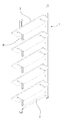
1 shows a window frame mounting shelf mounted on a window frame according to an embodiment of the present invention.
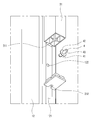
2 is a perspective view of the window frame mounting shelf of FIG. 1 viewed from above.
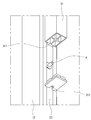
Fig. 3 is a perspective view of the window frame mounting shelf of Fig. 1 viewed from below.
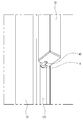
4 is an enlarged view of a portion A in Fig.
Fig. 5 is an enlarged view of the window frame mounting shelf of Fig. 1 viewed from below.
FIGS. 6 to 9 are views showing a coupling relation between the shelf support member, the latch member, and the lower frame of the window frame placing shelf of FIG.
Fig. 10 shows the coupling relationship between the upper frame and the lower frame of the window frame mounting shelf of Fig. 1. Fig.
Hereinafter, a window frame mounting shelf (hereinafter referred to as a " window frame mounting shelf ") according to an embodiment of the present invention will be described in detail with reference to the drawings.
1, the window frame mounting shelf includes a
Specifically, the
In the present embodiment, the
Here, as shown in FIG. 4,
5 and 6, the
On the other hand, the
As shown in FIG. 6, a plurality of through
An engaging member (4) to which the lathe supporting member (31) is engaged is inserted into these through holes (122).
The
A
4, the reinforcing
This allows the reinforcing
10, the window frame mounting shelf according to the present embodiment is configured such that the
A
Hereinafter, the operation of the window frame mounting shelf according to one embodiment of the present invention will be described.
When the window frame mounting shelf according to the present embodiment is installed on an existing window frame of an apartment veranda or the like, there is a need to adjust its height as necessary. 10, the frame
On the other hand, the
That is, the
The first projecting
As described above, the window frame mounting shelf according to the present invention can be installed on the window frame veranda, and can slide the shelf efficiently while being slidable, and also can install the required number of shelves at desired positions, And the safety was improved through the joint structure.
While the present invention has been particularly shown and described with reference to exemplary embodiments thereof, it is to be understood that the invention is not limited to the disclosed exemplary embodiments, Of the right.
1 ... frame,
11 ... upper frame, 12 ... lower frame
111 ... guide projection insertion groove, 112 ... concave portion
121 ... guide groove
122 ... through hole
2: reinforcing member,
3 ... shelf
31 ... rack supporting member, 312 ... space
4 ... engaging member
41 ... insertion portion, 42 ... insertion portion
43 ... engaging portion
6: frame length adjusting member
Claims (7)
A reinforcing member disposed in the frame and supporting the frame,
At least one shelf
/ RTI >
Wherein the frame has an upper frame and a lower frame which are slidable relative to each other,
A guide groove is formed in the longitudinal direction of the lower frame,
The shelf includes a shelf support member having a first projection inserted into the guide groove and slidable along the guide groove of the lower frame,
The shelf support member may be disposed at a predetermined position of the lower frame
Window frame mounting shelf.
A plurality of through holes spaced from each other are formed in the lower frame,
And an engaging member to which the lathe supporting member is hooked is inserted into the through hole
Window frame mounting shelf.
Wherein the engaging member includes an insertion portion to be inserted into the through hole, a fitting portion to which a part is disposed in a space formed between the first projecting portion and the guide groove facing each other, and a latching portion for supporting the lathe supporting member
Window frame mounting shelf.
And a space for inserting at least a part of the latching portion is formed on the bottom surface of the shelf support member.
Wherein the reinforcing member has a second protrusion inserted into the guide groove so as not to be separated from the guide groove,
The reinforcing member and the lower frame are fixed to each other by a bracket whose one end is fixed to the reinforcing member and the other end is fixed to the lower frame
Window frame mounting shelf.
Further comprising a frame length adjusting member capable of fixing or releasably fixing the upper frame to the lower frame by contacting or releasing the upper frame through the lower frame
Window frame mounting shelf.
Wherein the upper frame is provided with a concave portion such that when the engaging member is inserted into the through hole, the insertion portion does not contact the upper frame.
Priority Applications (1)
| Application Number | Priority Date | Filing Date | Title |
|---|---|---|---|
| KR1020150112915A KR20170019059A (en) | 2015-08-11 | 2015-08-11 | Rack for window frame |
Applications Claiming Priority (1)
| Application Number | Priority Date | Filing Date | Title |
|---|---|---|---|
| KR1020150112915A KR20170019059A (en) | 2015-08-11 | 2015-08-11 | Rack for window frame |
Publications (1)
| Publication Number | Publication Date |
|---|---|
| KR20170019059A true KR20170019059A (en) | 2017-02-21 |
Family
ID=58313846
Family Applications (1)
| Application Number | Title | Priority Date | Filing Date |
|---|---|---|---|
| KR1020150112915A KR20170019059A (en) | 2015-08-11 | 2015-08-11 | Rack for window frame |
Country Status (1)
| Country | Link |
|---|---|
| KR (1) | KR20170019059A (en) |
Cited By (2)
| Publication number | Priority date | Publication date | Assignee | Title |
|---|---|---|---|---|
| KR20220005802A (en) * | 2020-07-07 | 2022-01-14 | 송원용 | shelf device |
| KR20220002308U (en) * | 2021-03-19 | 2022-09-27 | 김안이 | Cat tower |
Citations (1)
| Publication number | Priority date | Publication date | Assignee | Title |
|---|---|---|---|---|
| KR200437008Y1 (en) | 2006-10-27 | 2007-10-24 | 김도형 | multipurpose shelf |
-
2015
- 2015-08-11 KR KR1020150112915A patent/KR20170019059A/en not_active Application Discontinuation
Patent Citations (1)
| Publication number | Priority date | Publication date | Assignee | Title |
|---|---|---|---|---|
| KR200437008Y1 (en) | 2006-10-27 | 2007-10-24 | 김도형 | multipurpose shelf |
Cited By (2)
| Publication number | Priority date | Publication date | Assignee | Title |
|---|---|---|---|---|
| KR20220005802A (en) * | 2020-07-07 | 2022-01-14 | 송원용 | shelf device |
| KR20220002308U (en) * | 2021-03-19 | 2022-09-27 | 김안이 | Cat tower |
Similar Documents
| Publication | Publication Date | Title |
|---|---|---|
| US8132768B2 (en) | Shelving end brackets with interchangeable pieces for supporting hang rods of different sizes | |
| US9655443B2 (en) | Adjustable shelf support system for medicine cabinets | |
| US20220061523A1 (en) | Storage systems including back channels and walls mountable along the back channels | |
| KR20170019059A (en) | Rack for window frame | |
| KR20100067349A (en) | Laundry drying stand for installation of window | |
| US10575634B1 (en) | Over and under closet rod and shelf supports | |
| KR20170100949A (en) | A hanger device for furniture | |
| US2996193A (en) | Suspendable furniture assembly | |
| KR20160015985A (en) | Rack for window frame | |
| KR20210113844A (en) | Multipurpose shelf | |
| US20160066729A1 (en) | Clothes hanging device | |
| KR200473928Y1 (en) | Furniture-loading clothes | |
| KR101804754B1 (en) | Extractable closet tweeser | |
| JP2009002100A (en) | Continuous panel wall structure | |
| CN210766036U (en) | Portable windowsill clothes hanger | |
| KR102552100B1 (en) | Built-in storage | |
| US9427082B2 (en) | Rotating storage cabinet for corner installation | |
| KR200368834Y1 (en) | A hanger fixing device | |
| KR200352622Y1 (en) | Display rack for a dress room | |
| KR200466241Y1 (en) | Bathroom shelf | |
| KR20170042856A (en) | Multi-purpose storage apparatus | |
| KR200479896Y1 (en) | Fixing member for wall attachment shelf | |
| KR200199558Y1 (en) | Fixed furniture | |
| KR200481593Y1 (en) | Drying rack | |
| KR20140000778U (en) | Rail for installation drawer |
Legal Events
| Date | Code | Title | Description |
|---|---|---|---|
| A201 | Request for examination | ||
| E902 | Notification of reason for refusal | ||
| E601 | Decision to refuse application |