KR20170018017A - Radio communication - Google Patents
Radio communication Download PDFInfo
- Publication number
- KR20170018017A KR20170018017A KR1020177000596A KR20177000596A KR20170018017A KR 20170018017 A KR20170018017 A KR 20170018017A KR 1020177000596 A KR1020177000596 A KR 1020177000596A KR 20177000596 A KR20177000596 A KR 20177000596A KR 20170018017 A KR20170018017 A KR 20170018017A
- Authority
- KR
- South Korea
- Prior art keywords
- sequence
- radio receiver
- radio
- correlator
- data
- Prior art date
Links
Images

Classifications
-
- H—ELECTRICITY
- H04—ELECTRIC COMMUNICATION TECHNIQUE
- H04L—TRANSMISSION OF DIGITAL INFORMATION, e.g. TELEGRAPHIC COMMUNICATION
- H04L27/00—Modulated-carrier systems
- H04L27/18—Phase-modulated carrier systems, i.e. using phase-shift keying
- H04L27/20—Modulator circuits; Transmitter circuits
- H04L27/2003—Modulator circuits; Transmitter circuits for continuous phase modulation
- H04L27/2007—Modulator circuits; Transmitter circuits for continuous phase modulation in which the phase change within each symbol period is constrained
- H04L27/2017—Modulator circuits; Transmitter circuits for continuous phase modulation in which the phase change within each symbol period is constrained in which the phase changes are non-linear, e.g. generalized and Gaussian minimum shift keying, tamed frequency modulation
-
- H—ELECTRICITY
- H04—ELECTRIC COMMUNICATION TECHNIQUE
- H04B—TRANSMISSION
- H04B1/00—Details of transmission systems, not covered by a single one of groups H04B3/00 - H04B13/00; Details of transmission systems not characterised by the medium used for transmission
- H04B1/69—Spread spectrum techniques
- H04B1/707—Spread spectrum techniques using direct sequence modulation
- H04B1/7073—Synchronisation aspects
-
- H—ELECTRICITY
- H04—ELECTRIC COMMUNICATION TECHNIQUE
- H04J—MULTIPLEX COMMUNICATION
- H04J13/00—Code division multiplex systems
- H04J13/0074—Code shifting or hopping
-
- H—ELECTRICITY
- H04—ELECTRIC COMMUNICATION TECHNIQUE
- H04J—MULTIPLEX COMMUNICATION
- H04J13/00—Code division multiplex systems
- H04J13/10—Code generation
-
- H—ELECTRICITY
- H04—ELECTRIC COMMUNICATION TECHNIQUE
- H04L—TRANSMISSION OF DIGITAL INFORMATION, e.g. TELEGRAPHIC COMMUNICATION
- H04L27/00—Modulated-carrier systems
- H04L27/18—Phase-modulated carrier systems, i.e. using phase-shift keying
-
- H—ELECTRICITY
- H04—ELECTRIC COMMUNICATION TECHNIQUE
- H04L—TRANSMISSION OF DIGITAL INFORMATION, e.g. TELEGRAPHIC COMMUNICATION
- H04L27/00—Modulated-carrier systems
- H04L27/18—Phase-modulated carrier systems, i.e. using phase-shift keying
- H04L27/20—Modulator circuits; Transmitter circuits
- H04L27/2003—Modulator circuits; Transmitter circuits for continuous phase modulation
-
- H—ELECTRICITY
- H04—ELECTRIC COMMUNICATION TECHNIQUE
- H04L—TRANSMISSION OF DIGITAL INFORMATION, e.g. TELEGRAPHIC COMMUNICATION
- H04L27/00—Modulated-carrier systems
- H04L27/18—Phase-modulated carrier systems, i.e. using phase-shift keying
- H04L27/22—Demodulator circuits; Receiver circuits
-
- H—ELECTRICITY
- H04—ELECTRIC COMMUNICATION TECHNIQUE
- H04L—TRANSMISSION OF DIGITAL INFORMATION, e.g. TELEGRAPHIC COMMUNICATION
- H04L27/00—Modulated-carrier systems
- H04L27/18—Phase-modulated carrier systems, i.e. using phase-shift keying
- H04L27/22—Demodulator circuits; Receiver circuits
- H04L27/233—Demodulator circuits; Receiver circuits using non-coherent demodulation
-
- H—ELECTRICITY
- H04—ELECTRIC COMMUNICATION TECHNIQUE
- H04L—TRANSMISSION OF DIGITAL INFORMATION, e.g. TELEGRAPHIC COMMUNICATION
- H04L27/00—Modulated-carrier systems
- H04L27/26—Systems using multi-frequency codes
- H04L27/2601—Multicarrier modulation systems
- H04L27/2647—Arrangements specific to the receiver only
- H04L27/2655—Synchronisation arrangements
- H04L27/2657—Carrier synchronisation
- H04L27/2659—Coarse or integer frequency offset determination and synchronisation
-
- H—ELECTRICITY
- H04—ELECTRIC COMMUNICATION TECHNIQUE
- H04L—TRANSMISSION OF DIGITAL INFORMATION, e.g. TELEGRAPHIC COMMUNICATION
- H04L27/00—Modulated-carrier systems
- H04L27/26—Systems using multi-frequency codes
- H04L27/2601—Multicarrier modulation systems
- H04L27/2647—Arrangements specific to the receiver only
- H04L27/2655—Synchronisation arrangements
- H04L27/2662—Symbol synchronisation
-
- H—ELECTRICITY
- H04—ELECTRIC COMMUNICATION TECHNIQUE
- H04L—TRANSMISSION OF DIGITAL INFORMATION, e.g. TELEGRAPHIC COMMUNICATION
- H04L7/00—Arrangements for synchronising receiver with transmitter
-
- H—ELECTRICITY
- H04—ELECTRIC COMMUNICATION TECHNIQUE
- H04L—TRANSMISSION OF DIGITAL INFORMATION, e.g. TELEGRAPHIC COMMUNICATION
- H04L27/00—Modulated-carrier systems
- H04L27/0014—Carrier regulation
- H04L2027/0044—Control loops for carrier regulation
- H04L2027/0046—Open loops
-
- H—ELECTRICITY
- H04—ELECTRIC COMMUNICATION TECHNIQUE
- H04L—TRANSMISSION OF DIGITAL INFORMATION, e.g. TELEGRAPHIC COMMUNICATION
- H04L27/00—Modulated-carrier systems
- H04L27/0014—Carrier regulation
- H04L2027/0044—Control loops for carrier regulation
- H04L2027/0063—Elements of loops
- H04L2027/0065—Frequency error detectors
-
- H—ELECTRICITY
- H04—ELECTRIC COMMUNICATION TECHNIQUE
- H04L—TRANSMISSION OF DIGITAL INFORMATION, e.g. TELEGRAPHIC COMMUNICATION
- H04L23/00—Apparatus or local circuits for systems other than those covered by groups H04L15/00 - H04L21/00
- H04L23/02—Apparatus or local circuits for systems other than those covered by groups H04L15/00 - H04L21/00 adapted for orthogonal signalling
Abstract
The radio transmitter 4 receives one or more variable message bits and encodes each message having a first value as a predetermined first binary chip sequence and transmits each message bit having an opposite value as a predetermined second binary chip sequence And an encoder 5 for encoding the data. A radio transmitter (4) transmits data packets, each packet comprising (i) a predetermined synchronization portion comprising one or more instances of a first binary chip sequence, and (ii) one or more encoded And a variable data portion containing message bits. The radio receiver 9 receives these data packets. It uses the synchronized portion of the received data packet to perform frequency and / or timing synchronization operations and then decodes the message bits from the data portion of the data packet.
Description
The present invention relates to radio transmitters and receivers for delivering binary data.
Various radio communication systems for transmitting binary message data are known. Examples include Bluetooth ™ and Bluetooth Low Energy ™. In order for the radio receiver to be able to reliably decode the message data, it is important to quickly and accurately determine the timing synchronization from the received data packet. Near the beginning of each data packet, it is known to include a predetermined synchronization sequence, previously known to both the transmitter and the receiver. The receiver may use this to perform operations such as frequency synchronization, phase synchronization, symbol timing estimation, and automatic gain control (AGC) training before decoding the payload message data.
When the received radio signal is weak (e.g., because there is a significant distance between the transmitter and the receiver), it may be difficult for the receiver to obtain accurate synchronization. Attempts to mitigate this can cause considerable additional complexity within the radio receiver. The present invention seeks to provide a novel approach that facilitates a particularly efficient radio receiver design with good performance at low signal levels.
From the first aspect, the present invention provides a method and apparatus for receiving one or more variable message bits and encoding each message bit having a first value as a predetermined first binary chip sequence and for each of the message bits having opposite values as a predetermined second binary chip sequence Wherein the radio transmitter is configured to transmit data packets, each packet including (i) one or more instances of the first binary chip sequence, and A determined synchronization portion, and (ii) one or more encoded message bits output by the encoder.
From a second aspect, the invention provides a radio receiver comprising:
Receiving data packets, each packet comprising a predetermined synchronization portion comprising one or more instances of a predetermined first binary chip sequence, and a variable data portion comprising one or more encoded message bits, wherein the first value Each message bit having an opposite value is encoded as a predetermined second binary chip sequence; receiving the data packets;
Prior to decoding the data portion of the data packet, using a synchronization portion of the received data packet to perform a frequency and / or timing synchronization operation;
And to decode message bits from the data portion of the data packet.
From a third aspect, the present invention provides a radio communication system including a radio transmitter and a radio receiver,
The radio transmitter comprising:
An encoder configured to receive one or more variable message bits and to encode each message bit having a first value as a predetermined first binary chip sequence and to encode each message bit having an opposite value as a predetermined second binary chip sequence, ;
Data packets, each packet comprising (i) a predetermined synchronization portion comprising one or more instances of the first binary chip sequence, and (ii) one or more encoded message bits output by the encoder Comprising variable data portions,
The radio receiver comprising:
Receive the data packets transmitted by the radio transmitter;
Prior to decoding the data portion of the data packet, using the synchronization portion of the received data packet to perform a frequency and / or timing synchronization operation;
And to decode the message bits from a data portion of the data packet.
According to a fourth aspect, the present invention provides a radio communication method comprising:
The method comprising: transmitting a data packet by radio, the data packet comprising (i) a predetermined synchronization portion comprising one or more instances of a first binary chip sequence, and (ii) a data portion comprising one or more encoded message bits Wherein each message bit having a first value is encoded as a predetermined first binary chip sequence and each message bit having an opposite value is encoded as a predetermined second binary chip sequence;
Receiving the data packet;
Using the synchronized portion of the received data packet to perform frequency and / or timing synchronization operations; And
And decoding the message bits from the data portion of the received data packet.
Thus, it will be appreciated that the same binary chip sequence is used for both synchronization and data encoding. This allows a particularly efficient radio receiver design, since much of the circuitry at the receiver can be shared for both purposes. In particular, the receiver may use a fixed-coefficient correlator for both operations, as described in more detail below.
In some embodiments, the synchronization portion and the variable data portion are frequency-shift-keying (FSK); Preferably Gaussian FSK (GFSK); And more preferably modulated on a radio carrier using a two-level GFSK. When GFSK modulation is used, a modulation index of approximately 0.5 is preferred (preferably within about 20% of 0.5, or more preferably within about 10% of 0.5, such as between about 0.45 and about 0.55) in). In some embodiments, the radio receiver may be configured to demodulate received data portions using a differential-binary-phase-shift-keying (DBPSK) demodulator. This is possible because, for appropriate first and second binary chip sequences, the transmitted signal modulated using GFSK can have the qualities of the DBPSK signal. In particular, for appropriate sequences, the receiver may decode data based on phase differences between portions of consecutive sequences in the data portion, as described in more detail below.
The frequency of the carrier wave may vary between successive data packets according to a predetermined frequency-hopping sequence. The radio transmitter and / or receiver may be configured to transmit and receive data, as defined in the Bluetooth 占 specification, such as the Bluetooth 占 low energy 占 physical layer specification section of the Bluetooth 占 Core Specification 4.0 published on June 30, 2010, A physical layer, and optionally other layers.
The first binary chip sequence may be of any length, but is preferably an even number of bit lengths of four or more. It may be, for example, bits of
The first binary chip sequence is preferably phase neutral when modulated using GFSK; That is, it is such that the phase of the modulated carrier signal with the first binary chip sequence is substantially the same at the beginning and end of the first binary chip sequence. The second binary chip sequence is preferably also phase neutral. This is advantageous because it allows the radio receiver to more easily identify the first and second binary chip sequences in the data portion, since a constant phase can be assumed to be at the end of each chip sequence. It can also enable better automatic frequency control on the receiver.
The first binary chip sequence preferably consists of the same number of 0 bits and 1 bit. The second binary chip sequence preferably also comprises the same number of 0 bits and 1 bit. This is advantageous because, when using GFSK modulation, it means that any modulation errors are automatically erased on the sequence and therefore need not be estimated or tracked at the receiver.
The second binary chip sequence is preferably identical to the first binary chip sequence except for a plurality of other predetermined bit positions. This number is preferably less than half the length of the first binary chip sequence. It is preferably an even number. In some preferred embodiments, the first and second binary chip sequences are different at precisely two bit positions, preferably first and last bit positions. This may allow efficient use of the correlator at the radio receiver, as will be described in more detail below.
The second binary chip sequence is preferably different from the first binary chip sequence at least in the first and last bit positions. In particularly preferred embodiments, the first and second chip sequences are identical to one another, except for their different first and last bit positions. The first chip sequence preferably has different binary values at the first and last bit positions (thus, the first chip sequence is also the second sequence in the different embodiments at the first and last positions). This is because the last chip of the sequence in the data part is different from the first chip in the sequence immediately following the two message bits (two '1' message bits, or two '0' message bits) And will have the same value each time the two message bits differ (message bits ('10', or '0 1')). When using GFSK modulation with a modulation index of approximately 0.5, this results in a phase shift of approximately 0 or approximately? Between intermediate sections of adjacent sequences (i.e., for the entire sequence except for the first and last bit positions) . This is because every '1' bit in the sequence causes a phase shift of Π / 2 positive, while all '0' causes a π / 2 negative phase shift. The presence or absence of a phase shift between adjacent sequences is determined by the value of the basic message bits. This simply allows the radio receiver to decode the message bits by determining the phase shifts between successive chip sequences in the data portion of the received packet. While no phase shift represents the repetition of the same message bit, the phase shift represents a change in the message bit. The radio receiver can use this difference information to decode the basic message data. It may determine whether the first message bit should be decoded as a '0' or '1' based on whether there is a phase change between the first message chip sequence and the last chip sequence of the synchronization part. Alternatively, in some embodiments, the message data may already be differentially encoded before it is transmitted by the radio transmitter; In this case, the original data can be directly determined using a differential decoder on the radio receiver.
If the GFSK modulation index is not exactly 0.5, the same approach may still be used, but the phase shift will be approximately 0 or a further removed value from? (Depending on how far the modulation index is from 0.5).
The first binary chip sequence preferably has a constraint that for a set of all possible sequences of a given length the sequence must have the same number of 0 bits and 1 bit and that it has first and last bits with different values from one another To have maximum autocorrelation performance. This allows the receiver to perform reliable synchronization timing by applying correlation operations to the received synchronization portion and also to reliably decode the message bits. Sequences that do not have these attributes may nevertheless still be useful. In some embodiments, any sequence with an autocorrelation quality of less than 0.3, or preferably less than 0.28, or more preferably less than 0.26 may be applied to any one or more of the additional constraints mentioned elsewhere in this application And the autocorrelation quality for the sequence may be used to determine the maximum sidelobe amplitude versus the maximum sidelobe amplitude when the sequence is correlated with the pulse train of 4-sequence- Is determined as the ratio of the zero-lag peak amplitude.
The 16-chip sequence ([0 0 0 1 1 0 1 0 1 1 0 0 1 0 1 1]), its bitwise complement, inverse sequence, and inverse bitwise complement are particularly good when used as the first binary chip sequence ≪ / RTI > performance. Particularly preferred embodiments use one of these sequences. The second binary chip sequence is then shifted to the first chip sequence, i.e. [1 0 0 1 1 0 1 0 1 1 0 0 1 0 0] where the first and last bits are flipped, Reverse sequence, or inverse bitwise complement (respectively).
The predetermined synchronization portion of the data packets preferably includes instances between one and two and about thirty of the first binary chip sequence; And more preferably between about 5 and about 30 instances. In some embodiments, it includes exactly or approximately 15 instances. This includes (i) having enough instances to allow reliable synchronization, and to allow any drift correction at the receiver to be resolved before the data portion arrives, and (ii) Is considered to be a particularly good trade-off between keeping data packets as short as possible to reduce the power consumption of the system. The sequence instances in the synchronization portion preferably follow immediately after one another, without any gaps. The data portion preferably follows the synchronization portion without any gap. The receiver is preferably configured to perform a tracking of at least the synchronization portion. By including the synchronization portion and the data portion in the same data packet without substantially any gaps therebetween, there is no loss of phase information between the two portions, and a particularly efficient side across the entire data packet allows tracking .
The radio receiver preferably includes a correlator. The receiver is preferably configured to use a correlator when performing frequency and / or timing synchronization operations. The receiver may, for example, use a correlator output for frequency ramp tracking as part of an automatic frequency control (AFC) loop. The correlator is preferably a fixed-coefficient correlator. This is desirable because it can be implemented in silicon with a relatively small number of gates. Reusing the same correlator for synchronization and for data correlation leads to a small receiver footprint and reduced complexity. The correlator may be configured to correlate the received signal with the first binary chip sequence and / or its sub-sequence. In some embodiments, it may be configured to, when processing the synchronization portion, correlate the received signal with a combination of two or more copies of the first binary chip sequences; For example, it may be a 32-bit correlator and may be configured to correlate a received synchronization portion with a 32-bit pattern consisting of two copies of a 16-bit first binary chip sequence, one after the other . This 32-bit correlator can be simulated by applying appropriate processing to the output of the 16-bit correlator. Such a multi-length correlator is preferably configured to return a received signal to a correlation for a single instance of the first binary chip sequence, or a sub-sequence thereof, when processing the data portion of the received signal.
The correlator is preferably arranged to correlate the received signal with a sub-sequence of the first binary chip sequence. It may be switchable between two modes: a second mode for correlating a first mode that correlates to a complete first binary chip sequence and a sub-sequence of a first binary chip sequence. The sub-sequence is preferably defined by bit positions where the first and second binary chip sequences have the same values. The sub-sequence is preferably an adjacent sequence of bits from the first binary chip sequence. For example, if the first chip sequence is a 16-bit sequence and the second chip sequence is only different in only the first and last bit positions, then the correlator will only correlate the middle 14 bits of the sequences when in the first mode It will be possible. The radio receiver may use the first mode when processing the synchronized portion of the received data packet and may switch the correlator to the second mode when decoding the message bits from the data portion.
This idea is novel in its own right and, from a further aspect, the invention provides a first mode in which it is configured to correlate a received signal to a binary chip sequence, and a second mode in which it receives a received signal for a short sub- Coefficient correlator that is switchable between a first mode configured to correlate a sub-sequence with a first mode and a second mode configured to correlate a sub-sequence with a second mode configured to correlate a sub- And outputs a signal indicative of the phase shift. The radio receiver may be configured to use the output from the correlator to decode the message data from the received signal. Features of previous aspects and embodiments may also be features of embodiments of this aspect.
The correlator is preferably configured to output the amplitude information. The radio receiver may use this amplitude information to perform symbol timing synchronization. The correlator is preferably also configured to output phase information. The radio receiver is preferably configured to use this phase information to perform initial frequency synchronization. The radio receiver can also be configured to use this information to perform on-going frequency shift tracking and to apply appropriate adjustments or compensation when the frequency is shifted. This is particularly simple when the binary chip sequences are phase neutral, as in the preferred embodiments, since the phase should always return to zero after each sequence if there is no frequency shift.
The radio receiver is preferably arranged to use a correlator to determine whether a sub-sequence in a data portion of a received data packet has a substantially zero or approximately? Phase change relative to a previous sub-sequence in the data portion. The correlator preferably outputs a signal representative of this phase change, suitable for the radio receiver to use to determine the message bits.
Alternatively, in embodiments of any of the aspects of the present application, the receiver may include a fixed-coefficient correlator that correlates the received signal for a shorter subsequence for both the data portion and the synchronization portion have. The correlator can be configured to ignore all these bit positions that are different from the first binary chip sequence and instead correlate on those positions where they agree. This may result in lower synchronization performance, but it will reduce the size and complexity of the receiver. This correlator preferably outputs a signal representative of this phase change, which determines whether the sub-sequence in the data portion has a roughly zero or? Phase change relative to the previous sub-sequence in the data portion, Can be used to determine.
The data portion of the data packet may comprise any suitable information, such as any one or more of address information, data payload, error-correction information, and the like. The data packets may be transmitted and received on a predetermined schedule or irregularly.
In some embodiments of the invention, the '1' bit (or equivalently, the '0' bit) in the synchronization portion and the data portion is preferably any 16-bit pattern One bitwise complement and / or inverted reflection) is used. The opposite bit values in the data portion may be represented with the same sequence but with the first and last bit values flipped.
The table shows possible 16-bit sequences for the autocorrelation quality, and the quality values shown for the sequences indicate that when the sequence is correlated with a pulse train of four sequence-repetitions (determined by simulation), the maximum side lobe amplitude The ratio of large zero-lag peak amplitude. Sequences toward the top of the table are preferred, but any of these sequences, or others, can still be advantageously used with embodiments of the present invention.

In some embodiments, the receiver may perform a 32-bit correlation operation on the synchronized portion of the received data packet by correlating the two copies of the 16-bit first binary chip sequence, one after the other . This correlator will match the pairs of instances of the repeated 16-bit sequence that occur in the synchronization portion. In the simulations of these embodiments, 16-bit sequences providing optimal autocorrelation have been found to be different from those used in 16-bit correlators. They are provided in the following table.
Bit (or equivalently ' 0 ' bit) in the data portion is any 16-bit pattern (or one of the entries) taken from the table below Bitwise complement and / or inverted reflection). The opposite bit values in the data portion may be represented with the same sequence but with the first and last bit values flipped. The quality value is based on the same given definition given above.

The radio transmitter may be embodied as a whole or generally as an integrated circuit. It may include, or be configured to communicate with, a microcontroller or other processor. It may be configured to receive message data from a microcontroller, processor, or other logic device, and to transmit message data by radio. The radio receiver may be embodied as an overall or, generally, integrated circuit. It may include, or be configured to communicate with, a microcontroller or other processor. It may be configured to decode the message data from one or more received data packets and output the message data to a microcontroller, processor, or other logic device. In some embodiments, the radio transmitter includes or is communicatively coupled to an input source such as a button, keyboard, touch screen or other sensor. In some embodiments, the radio receiver includes or is communicatively coupled to an output, such as a display, loudspeaker, or indicator.
The features of any aspect or embodiment described in this application may be applied to any other aspect or embodiment described in the present application where appropriate. Where reference is made to different embodiments or sets of embodiments, it should be understood that they are not necessarily individual and may overlap.
Certain preferred embodiments of the present invention will now be described, by way of example only, with reference to the accompanying drawings.
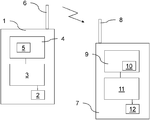
1 is a schematic diagram of a radio communication system embodying the present invention.
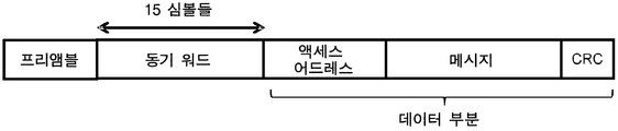
2 is a diagram of a data packet that may be transmitted and received by a radio communication system.
3 is a schematic diagram of a portion of a radio transmitter embodying the present invention.
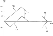
Figure 4 is a plot of the phase versus time for two different chip sequences.
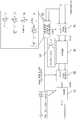
5 is a schematic diagram of a portion of a radio receiver embodying the present invention.
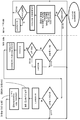
Figure 6 is a state diagram for such a radio receiver.
Fig. 1 shows a wireless
The wireless
The
In use, the wireless heart rate monitor (1) receives periodic heart rate readings from a heart rate sensor (2) for a human user. The
The
Figure 2 shows a representative data packet structure, including a fixed preamble, a synchronization portion (synchronization word), and a data portion. The data portion includes an access address, message bits, and a cyclic-redundancy check (CRC).
The
The radio receiver 9 then uses the 14-bit sub-sequence ([0 0 1 1 0 1 0 1 1 0 0 1 0 1], which is the shared, intermediate 14 bits contained in each of the two 16- ) With the received data portion. It separately processes the I and Q components to determine the phase shift between consecutive occurrences of sub-sequences in the data portion. The radio receiver 9 receives an initial phase reference (e.g., '1') from the synchronization portion to decode any sequence that has an inverse value for the immediately previous decoded message bit and shifts in phase by approximately 180 degrees. Decode the message data from the phase shift information by using an arbitrary sequence with a phase shift of about 0 degrees with the same value as the immediately decoded message bit (corresponding to the initially decoded bit value).
The radio receiver 9 performs tracking of the ongoing shift while processing the data packet, based on the phase information output by the
The radio receiver 9 can then extract the message from the decoded data, check the CRC, and perform any other suitable operations. It then forwards the decoded message data to the
The wireless
Figure 3 illustrates in greater detail elements within a radio transmitter embodying the present invention. This may be the
These radio transmitters first differentially encode the data bits using the
FIG. 4 illustrates two possible
Figure 5 illustrates in detail the digital baseband processing stage of a radio receiver embodying the present invention. This may be the same radio receiver 9 as described above, or it may be a different radio receiver.
Steps such as filtering and residual frequency offset tracking are not shown for reasons of brevity.
The design of a radio receiver aims to optimize sensitivity while accommodating realistic channel conditions (carrier frequency offset, carrier drift, fading, etc.). It uses correlation for timing synchronization and detection.
The complex-valued baseband samples are shown from the left side of FIG. These are transferred to the
Figure 5 includes the following abbreviations:
n = chip index;
m = symbol index;
z (n) = complex baseband samples;
z '(n) = carrier-frequency offset (CFO) compensation z (n); And
p (k) = complex values representing the chip sequence.
Synchronization is built on a particular type of correlator. The correlator is a data-assisted common timing and frequency estimator that utilizes the knowledge of the data in the received symbols to cancel the effect of modulation on the estimates of the conventional delay-and correlation-type carrier frequency offset estimator. The principle of supporting synchronization is described by the Applicant in WO 2014/167318, the entire contents of which are incorporated herein by reference.
The performance of the radio receiver of FIG. 5 can be analyzed as follows, assuming ideal synchronization.
For discriminator detection of FSK signaling with a modulation index of h = 0.5, E b / N o for bit error rate (BER) = 0.001
Detector detection will generally outperform non-coherent detection of correlated binary signaling for this modulation index. However, by correlating behind the discriminator, the discriminator here operates below the FM "threshold" - the area where the detector performance deteriorates rapidly.
For differential detection of DBPSK, E b / N o for bit error rate (BER) = 0.001
In Figure 5, the "common timing and frequency offset sync"

Where L is the number of samples representing the up-sampled "synchronization word" (such as the specified 16-bit sequence); Where D is a lag determined at design time; Where T is the sample period.
The coefficients are given as d i = p i * p i + D , where p is the samples constituting the upsampled and modulated synchronous word bits. The correlator is valid and should be sampled at the precise time point for the frequency offset estimate, and this time instant is when the "peak" is observed at the value of M n given by:

The effective peak at M n is determined for a programmable threshold. A successful synchronization event is defined by observing several effective peaks spaced in time by amounts corresponding to the value " DELTA " for considering the "sync word" length, plus or minus noise. This synchronization event further defines a strobe time to be used for later detection of data symbols.
The coefficients (d i = p i * p i + D ) are calculated at design time.
The DBPSK detection is implemented as follows.
The received sequence of complex baseband samples z (n) representing a sequence of GFSK-modulation chips is processed by a digital-to-baseband-
From here,
The message data bits are transmitted between consecutive received symbols
The coefficient p (k) is given by the following equation to correlate the N values of z (n) with the set of N complex coefficients representing the N GFSM modulation chips (for simplicity, assuming no oversampling from now on) Can be written as:
p (k) = e j ? k.
For simplicity, assuming that omega cfo = 0, the complex-value correlator output at time t is then given by:

Thus, the angular difference between C (t) and C (t + T s ) will be 0 or?.
If the angular difference is more than Π / 2 or less than -Π / 2, the detector will output '1'; Otherwise it will print '0'.
For coherence detection,
Synchronization or tracking of symbol timing may be performed when the "peak value" is | C (t) | Lt; RTI ID = 0.0 > time < / RTI >
The residual carrier frequency offset? Cfo is the result of the carrier-frequency shift and the initial carrier frequency offset estimation error and can be traced by looking at the angular difference between C (t) and C (t + T s ). After subtracting the known phase shift (after the determination) due to modulation ,? cfo can be estimated as:

Residual carrier frequency offset to [Hz] (
6 illustrates a finite state machine (FSM) capable of organizing synchronization processes and data reception at a radio receiver as illustrated in FIG.
The state of this FSM is given by the variable synstate. At time (t = 0) the FSM starts at syncstate = 0. In this state, the FSM is directed to the right side of the dashed line in FIG. 6 and finds "peaks" from the value of M n calculated by the
The average time of "peaks" as measured by the counter (the number of samples per symbol into the counts module) defines the symbol boundaries (strobe timing). Additionally, the initial carrier frequency offset estimate is calculated as the average of the elements in the vector (cfoVec). These values (
Now, with syncstate> 0, the FSM enters the left side of the dashed line in FIG. 6 to receive the payload. In this state, the message data bits are transmitted between successive received symbols in the
Claims (37)
Wherein the radio transmitter is configured to transmit data packets, each packet including (i) a predetermined synchronization portion comprising one or more instances of the first binary chip sequence, and (ii) Comprising a variable data portion comprising one or more encoded message bits
Radio transmitter.
And configured to modulate the synchronization portion and the variable data portion on a radio carrier using Gaussian frequency-shift-keying (GFSK)
Radio transmitter.
The GFSK modulation has a modulation index of approximately 0.5
Radio transmitter.
Wherein one or each of the first and second binary chip sequences is at least four,
Radio transmitter.
The first binary chip sequence is phase-neutral when it is modulated using GFSK
Radio transmitter.
Wherein one or each of the first and second binary chip sequences comprises the same number of 0 bits and 1 bit
Radio transmitter.
Wherein the second binary chip sequence is identical to the first binary chip sequence except at its other first and last bit positions.
Radio transmitter.
Wherein the first and last bits of the first binary chip sequence are different
Radio transmitter.
Wherein the first binary chip sequence is identical to the first binary chip sequence, the sequence being dependent on constraints that the sequence should have the same number of 0 bits and 1 bit and that it should have first and last bits with different values from one another Having a maximum autocorrelation performance for a set of all possible binary sequences of length
Radio transmitter.
Wherein the first binary chip sequence is determined as a ratio of a maximum sidelobe amplitude to a zero-lag peak amplitude when the sequence is correlated with a pulse train of four sequence- Having an autocorrelation quality of less than 0.26
Radio transmitter.
The first binary chip sequence may be a 16-bit sequence ([0 0 0 1 1 0 1 0 1 1 0 0 1 0 1 1]), or its inverse, or its bitwise complement, A conservative
Radio transmitter.
Wherein the predetermined synchronization portion of the data packets includes instances between two and about thirty of the first binary chip sequence
Radio transmitter.
Wherein the data portions of the data packets are followed by the synchronization portions without any gap
Radio transmitter.
Receiving data packets, each packet comprising a predetermined synchronization portion comprising one or more instances of a predetermined first binary chip sequence, and a variable data portion comprising one or more encoded message bits, wherein the first value Wherein each message bit having an opposite value is encoded as the first binary chip sequence and each message bit having an opposite value is encoded as a predetermined second binary chip sequence;
Prior to decoding the data portion of the data packet, using the synchronization portion of the received data packet to perform a frequency and / or timing synchronization operation;
And to decode message bits from the data portion of the data packet
Radio receiver.
(DPSK) demodulator for demodulating the data portion of the received data using a differential-binary-phase-shift-keying (DBPSK)
Radio receiver.
Wherein the controller is configured to use the correlator to perform the frequency and / or timing synchronization operations
Radio receiver.
The correlator is a fixed-coefficient correlator
Radio receiver.
Wherein the correlation is switchable between a first mode in which it correlates to a complete first binary chip sequence and a second mode in which it correlates to a subsequence of the first binary chip sequence, Containing a group
Radio receiver.
Configured to use the correlator in the first mode to process the synchronized portion of a received data packet and to switch the correlator to the second mode to decode message bits from the data portion
Radio receiver.
Wherein the sub-sequence is defined by bit positions in the first binary chip sequence in which the first and second binary chip sequences have identical values to each other
Radio receiver.
The sub-sequence consists of all bits of the first binary chip sequence except the first and last bits
Radio receiver.
Wherein the correlator is configured to output amplitude information and the radio receiver is configured to use the amplitude information to perform symbol timing synchronization
Radio receiver.
Wherein the correlator is configured to output phase information and the radio receiver is configured to use the phase information to perform initial frequency synchronization
Radio receiver.
Is configured to perform on-going frequency drift tracking and to use phase information from the correlator to apply the appropriate adjustment or compensation when the frequency of the received signal is shifted
Radio receiver.
Sequence from the correlator to determine whether the sub-sequence in the data portion of the received data packet has a substantially zero or approximately? Phase change relative to a previous sub-sequence in the data portion, And to use the correlator to use a signal representative of this phase change
Radio receiver.
The radio transmitter comprising:
An encoder configured to receive one or more variable message bits and to encode each message bit having a first value as a predetermined first binary chip sequence and to encode each message bit having an opposite value as a predetermined second binary chip sequence; ;
Data packets, each packet comprising (i) a predetermined synchronization portion comprising one or more instances of the first binary chip sequence, and (ii) one or more encoded message bits output by the encoder Comprising variable data portions,
The radio receiver comprising:
Receive the data packets transmitted by the radio transmitter;
Prior to decoding the data portion of the data packet, using the synchronization portion of the received data packet to perform a frequency and / or timing synchronization operation;
And to decode the message bits from the data portion of the data packet
Radio communication system.
The method comprising: transmitting a data packet by radio, the data packet comprising (i) a predetermined synchronization portion comprising one or more instances of a first binary chip sequence, and (ii) a data portion comprising one or more encoded message bits Wherein each message bit having a first value is encoded as a predetermined first binary chip sequence and each message bit having an opposite value is encoded as a predetermined second binary chip sequence;
Receiving the data packet;
Using the synchronized portion of the received data packet to perform frequency and / or timing synchronization operations; And
And decoding the message bits from the data portion of the received data packet
Radio communication method.
The correlator is configured to output a signal indicative of a phase shift between two consecutive occurrences of the sub-sequence in the received signal when in the second mode
Radio receiver.
And to use a signal indicative of a phase shift between two successive occurrences of the sub-sequence in a received signal to decode message data from a data portion of a received data packet
Radio receiver.
And to demodulate the data portion of the received data packet using a differential-binary-phase-shift-keying (DBPSK) demodulator
Radio receiver.
Configured to use the correlator to perform frequency and / or timing synchronization operations
Radio receiver.
Configured to use the correlator in the first mode to process a synchronized portion of a received data packet and to switch the correlator to the second mode to decode message bits from a data portion of the data packet
Radio receiver.
The sub-sequence consists of all bits of the binary chip sequence except the first and last bits
Radio receiver.
Wherein the correlator is configured to output amplitude information and the radio receiver is configured to use the amplitude information to perform symbol timing synchronization
Radio receiver.
Wherein the correlator is configured to output phase information and the radio receiver is configured to use the phase information to perform initial frequency synchronization
Radio receiver.
Configured to use the phase information from the correlator to perform an ongoing frequency shift tracking and to apply appropriate adjustments or compensation when the frequency of the received signal is shifted
Radio receiver.
Sequence from the correlator to determine whether the sub-sequence in the data portion of the received data packet has a substantially zero or approximately? Phase change relative to a previous sub-sequence in the data portion, And to use the correlator to use a signal representative of this phase change
Radio receiver.
Applications Claiming Priority (5)
| Application Number | Priority Date | Filing Date | Title |
|---|---|---|---|
| GBGB1410641.3A GB201410641D0 (en) | 2014-06-13 | 2014-06-13 | Radio communication |
| GB1410641.3 | 2014-06-13 | ||
| GBGB1410713.0A GB201410713D0 (en) | 2014-06-13 | 2014-06-16 | Radio communication |
| GB1410713.0 | 2014-06-16 | ||
| PCT/GB2015/051669 WO2015189584A1 (en) | 2014-06-13 | 2015-06-09 | Radio communication |
Publications (1)
| Publication Number | Publication Date |
|---|---|
| KR20170018017A true KR20170018017A (en) | 2017-02-15 |
Family
ID=51266612
Family Applications (1)
| Application Number | Title | Priority Date | Filing Date |
|---|---|---|---|
| KR1020177000596A KR20170018017A (en) | 2014-06-13 | 2015-06-09 | Radio communication |
Country Status (8)
| Country | Link |
|---|---|
| US (1) | US9942070B2 (en) |
| EP (1) | EP3155739A1 (en) |
| JP (1) | JP2017519468A (en) |
| KR (1) | KR20170018017A (en) |
| CN (1) | CN106464295A (en) |
| GB (3) | GB201410641D0 (en) |
| TW (1) | TW201547214A (en) |
| WO (1) | WO2015189584A1 (en) |
Families Citing this family (5)
| Publication number | Priority date | Publication date | Assignee | Title |
|---|---|---|---|---|
| US10187235B2 (en) * | 2016-07-01 | 2019-01-22 | Intel IP Corporation | Long range bluetooth low energy synchronization system |
| GB2557300A (en) | 2016-12-05 | 2018-06-20 | Nordic Semiconductor Asa | Demodulation |
| GB201620669D0 (en) | 2016-12-05 | 2017-01-18 | Nordic Semiconductor Asa | Digital radio communication |
| GB201907717D0 (en) * | 2019-05-31 | 2019-07-17 | Nordic Semiconductor Asa | Apparatus and methods for dc-offset estimation |
| GB2602683B (en) | 2021-05-06 | 2023-03-08 | Nordic Semiconductor Asa | Radio receiver synchronization |
Family Cites Families (16)
| Publication number | Priority date | Publication date | Assignee | Title |
|---|---|---|---|---|
| US4943974A (en) * | 1988-10-21 | 1990-07-24 | Geostar Corporation | Detection of burst signal transmissions |
| US5497395A (en) * | 1994-04-04 | 1996-03-05 | Qualcomm Incorporated | Method and apparatus for modulating signal waveforms in a CDMA communication system |
| US6493338B1 (en) | 1997-05-19 | 2002-12-10 | Airbiquity Inc. | Multichannel in-band signaling for data communications over digital wireless telecommunications networks |
| US6421371B1 (en) * | 1998-11-17 | 2002-07-16 | Ericsson Inc. | Modulation sequence synchronization methods and apparatus employing partial sequence correlation |
| DE60019773T2 (en) | 2000-12-20 | 2006-01-19 | Agilent Technologies, Inc. (n.d.Ges.d.Staates Delaware), Palo Alto | Detection of preambles of data packets |
| US20030043947A1 (en) | 2001-05-17 | 2003-03-06 | Ephi Zehavi | GFSK receiver |
| FI20030046A (en) | 2003-01-13 | 2004-07-14 | Nokia Corp | Modulation Method |
| US7295546B2 (en) * | 2003-02-26 | 2007-11-13 | Nokia Corporation | Method for synchronizing bluetooth packets |
| US7986725B2 (en) * | 2005-03-04 | 2011-07-26 | Nokia Corporation | Spread spectrum transmission systems |
| EP1838008A1 (en) * | 2006-03-23 | 2007-09-26 | Sony Deutschland Gmbh | Preamble for synchronization |
| EP2090005A2 (en) * | 2006-10-26 | 2009-08-19 | QUALCOMM Incorporated | Method and apparatus for packet detection in a wireless communications system |
| US7760821B2 (en) * | 2006-11-13 | 2010-07-20 | International Business Machines Corporation | Oversampled channel response identification |
| US8374291B1 (en) | 2009-02-04 | 2013-02-12 | Meteorcomm Llc | Methods for bit synchronization and symbol detection in multiple-channel radios and multiple-channel radios utilizing the same |
| FR2942576B1 (en) * | 2009-02-23 | 2011-02-18 | Commissariat Energie Atomique | METHOD OF ESTIMATING A CARRIER FREQUENCY OFFSET IN A TELECOMMUNICATION SIGNAL RECEIVER, IN PARTICULAR A MOBILE DEVICE |
| KR101188834B1 (en) * | 2009-08-13 | 2012-10-09 | 캐스코더 리미티드 | Wireless receiver |
| US9408147B2 (en) | 2012-09-24 | 2016-08-02 | Broadcom Corporation | Enhanced rate physical layer for Bluetooth™ low energy |
-
2014
- 2014-06-13 GB GBGB1410641.3A patent/GB201410641D0/en not_active Ceased
- 2014-06-16 GB GBGB1410713.0A patent/GB201410713D0/en not_active Ceased
-
2015
- 2015-06-02 TW TW104117759A patent/TW201547214A/en unknown
- 2015-06-09 CN CN201580031232.6A patent/CN106464295A/en active Pending
- 2015-06-09 JP JP2017517428A patent/JP2017519468A/en active Pending
- 2015-06-09 WO PCT/GB2015/051669 patent/WO2015189584A1/en active Application Filing
- 2015-06-09 EP EP15728127.0A patent/EP3155739A1/en not_active Withdrawn
- 2015-06-09 US US15/312,148 patent/US9942070B2/en not_active Expired - Fee Related
- 2015-06-09 KR KR1020177000596A patent/KR20170018017A/en unknown
- 2015-06-09 GB GB1509982.3A patent/GB2528769B/en not_active Expired - Fee Related
Also Published As
| Publication number | Publication date |
|---|---|
| GB201410641D0 (en) | 2014-07-30 |
| US9942070B2 (en) | 2018-04-10 |
| GB201410713D0 (en) | 2014-07-30 |
| WO2015189584A1 (en) | 2015-12-17 |
| JP2017519468A (en) | 2017-07-13 |
| GB2528769B (en) | 2017-11-08 |
| EP3155739A1 (en) | 2017-04-19 |
| GB2528769A (en) | 2016-02-03 |
| CN106464295A (en) | 2017-02-22 |
| GB201509982D0 (en) | 2015-07-22 |
| TW201547214A (en) | 2015-12-16 |
| US20170078125A1 (en) | 2017-03-16 |
Similar Documents
| Publication | Publication Date | Title |
|---|---|---|
| CA3041397C (en) | Optimized combination of preamble and data fields for sensor networks having low electricity consumption on the basis of the telegram splitting method | |
| KR100937602B1 (en) | Human body communication system and communication method thereof | |
| KR100837702B1 (en) | Carrier frequency recovery apparatus and method using phase shift | |
| US10686489B2 (en) | Radio communication | |
| KR20170018017A (en) | Radio communication | |
| CN105282021A (en) | Signal concentrator device | |
| WO2004088901A3 (en) | Method and system for synchronization in a frequency shift keying receiver | |
| US9614696B2 (en) | Alternating phase filter for increasing communication speeds, spectral efficiency and enabling other benefits | |
| US11070246B2 (en) | Digital radio communication | |
| US9847895B2 (en) | Modulation index shift signaling | |
| KR20070049832A (en) | Method and apparatus for estimating frequency offset in mobile communications system | |
| CN111010686B (en) | Parallel processing of dirty packets in bluetooth and bluetooth low energy systems | |
| WO2004095720A3 (en) | Timing synchronization for m-dpsk channels | |
| CN112105958B (en) | Bipolar CSK modulation composite text signal broadcasting method and device | |
| JP4800886B2 (en) | Receiving apparatus and receiving method | |
| WO2001052493A1 (en) | Method for blind modulation detection | |
| CN103067117B (en) | Digital signal receive-transmit system and receiving/transmission method | |
| CN110235377A (en) | Demodulator | |
| KR100363382B1 (en) | Apparatus for compensating multipath fading channels in wireless personal area network | |
| KR100882435B1 (en) | Method for symbol timing estimation based on ir-uwb systems | |
| CN104202114B (en) | Digital signal receive-transmit system and receiving/transmission method | |
| JP2001285134A (en) | Spread spectrum communication equipment | |
| KR20100059515A (en) | Apparatus and method for acquisitioning symbol synchronization in a non-coherent asynchronous receiver | |
| CN103152122A (en) | Transmit-receive system and transmit-receive method of digital signal |