KR20170017818A - Magnetic sensor, integrated circuit and motor assembly - Google Patents
Magnetic sensor, integrated circuit and motor assembly Download PDFInfo
- Publication number
- KR20170017818A KR20170017818A KR1020160100018A KR20160100018A KR20170017818A KR 20170017818 A KR20170017818 A KR 20170017818A KR 1020160100018 A KR1020160100018 A KR 1020160100018A KR 20160100018 A KR20160100018 A KR 20160100018A KR 20170017818 A KR20170017818 A KR 20170017818A
- Authority
- KR
- South Korea
- Prior art keywords
- state
- magnetic sensor
- magnetic
- output
- circuit
- Prior art date
Links
Images


Classifications
-
- H—ELECTRICITY
- H02—GENERATION; CONVERSION OR DISTRIBUTION OF ELECTRIC POWER
- H02K—DYNAMO-ELECTRIC MACHINES
- H02K1/00—Details of the magnetic circuit
- H02K1/06—Details of the magnetic circuit characterised by the shape, form or construction
- H02K1/12—Stationary parts of the magnetic circuit
- H02K1/14—Stator cores with salient poles
- H02K1/141—Stator cores with salient poles consisting of C-shaped cores
- H02K1/143—Stator cores with salient poles consisting of C-shaped cores of the horse-shoe type
-
- G—PHYSICS
- G01—MEASURING; TESTING
- G01R—MEASURING ELECTRIC VARIABLES; MEASURING MAGNETIC VARIABLES
- G01R33/00—Arrangements or instruments for measuring magnetic variables
- G01R33/0023—Electronic aspects, e.g. circuits for stimulation, evaluation, control; Treating the measured signals; calibration
-
- G—PHYSICS
- G01—MEASURING; TESTING
- G01R—MEASURING ELECTRIC VARIABLES; MEASURING MAGNETIC VARIABLES
- G01R19/00—Arrangements for measuring currents or voltages or for indicating presence or sign thereof
- G01R19/165—Indicating that current or voltage is either above or below a predetermined value or within or outside a predetermined range of values
- G01R19/16566—Circuits and arrangements for comparing voltage or current with one or several thresholds and for indicating the result not covered by subgroups G01R19/16504, G01R19/16528, G01R19/16533
- G01R19/16576—Circuits and arrangements for comparing voltage or current with one or several thresholds and for indicating the result not covered by subgroups G01R19/16504, G01R19/16528, G01R19/16533 comparing DC or AC voltage with one threshold
-
- G—PHYSICS
- G01—MEASURING; TESTING
- G01R—MEASURING ELECTRIC VARIABLES; MEASURING MAGNETIC VARIABLES
- G01R33/00—Arrangements or instruments for measuring magnetic variables
- G01R33/0088—Arrangements or instruments for measuring magnetic variables use of bistable or switching devices, e.g. Reed-switches
-
- G—PHYSICS
- G01—MEASURING; TESTING
- G01R—MEASURING ELECTRIC VARIABLES; MEASURING MAGNETIC VARIABLES
- G01R33/00—Arrangements or instruments for measuring magnetic variables
- G01R33/02—Measuring direction or magnitude of magnetic fields or magnetic flux
-
- H—ELECTRICITY
- H02—GENERATION; CONVERSION OR DISTRIBUTION OF ELECTRIC POWER
- H02K—DYNAMO-ELECTRIC MACHINES
- H02K11/00—Structural association of dynamo-electric machines with electric components or with devices for shielding, monitoring or protection
- H02K11/20—Structural association of dynamo-electric machines with electric components or with devices for shielding, monitoring or protection for measuring, monitoring, testing, protecting or switching
-
- H—ELECTRICITY
- H02—GENERATION; CONVERSION OR DISTRIBUTION OF ELECTRIC POWER
- H02K—DYNAMO-ELECTRIC MACHINES
- H02K11/00—Structural association of dynamo-electric machines with electric components or with devices for shielding, monitoring or protection
- H02K11/30—Structural association with control circuits or drive circuits
-
- H—ELECTRICITY
- H02—GENERATION; CONVERSION OR DISTRIBUTION OF ELECTRIC POWER
- H02P—CONTROL OR REGULATION OF ELECTRIC MOTORS, ELECTRIC GENERATORS OR DYNAMO-ELECTRIC CONVERTERS; CONTROLLING TRANSFORMERS, REACTORS OR CHOKE COILS
- H02P6/00—Arrangements for controlling synchronous motors or other dynamo-electric motors using electronic commutation dependent on the rotor position; Electronic commutators therefor
- H02P6/14—Electronic commutators
- H02P6/16—Circuit arrangements for detecting position
-
- H—ELECTRICITY
- H02—GENERATION; CONVERSION OR DISTRIBUTION OF ELECTRIC POWER
- H02P—CONTROL OR REGULATION OF ELECTRIC MOTORS, ELECTRIC GENERATORS OR DYNAMO-ELECTRIC CONVERTERS; CONTROLLING TRANSFORMERS, REACTORS OR CHOKE COILS
- H02P6/00—Arrangements for controlling synchronous motors or other dynamo-electric motors using electronic commutation dependent on the rotor position; Electronic commutators therefor
- H02P6/20—Arrangements for starting
- H02P6/22—Arrangements for starting in a selected direction of rotation
-
- H—ELECTRICITY
- H02—GENERATION; CONVERSION OR DISTRIBUTION OF ELECTRIC POWER
- H02P—CONTROL OR REGULATION OF ELECTRIC MOTORS, ELECTRIC GENERATORS OR DYNAMO-ELECTRIC CONVERTERS; CONTROLLING TRANSFORMERS, REACTORS OR CHOKE COILS
- H02P2203/00—Indexing scheme relating to controlling arrangements characterised by the means for detecting the position of the rotor
- H02P2203/09—Motor speed determination based on the current and/or voltage without using a tachogenerator or a physical encoder
Landscapes
- Physics & Mathematics (AREA)
- Engineering & Computer Science (AREA)
- Power Engineering (AREA)
- General Physics & Mathematics (AREA)
- Condensed Matter Physics & Semiconductors (AREA)
- Microelectronics & Electronic Packaging (AREA)
- Measuring Magnetic Variables (AREA)
- Measurement Of Current Or Voltage (AREA)
Abstract
Description
본 발명은 회로 기술 분야에 관한 것이다. 특히, 본 발명은 자기 센서에 관한 것이다.The present invention relates to the field of circuit technology. More particularly, the present invention relates to a magnetic sensor.
동기식 모터의 시작 동안, 고정자는 교번 자계를 생성하여 영구 자석 회전자가 발진하도록 한다. 회전자의 발진의 진폭은 회전자가 회전을 시작할 때까지 증가하고, 최종적으로 회전자는 고정자의 교번 자계와 동기식으로 회전하도록 가속된다. 종래 기술의 동기식 모터의 시작을 보장하기 위하여, 모터의 시작점은 낮게 설정되고, 그 결과 모터가 상대적으로 높은 동작점에서 동작할 수 없고, 이에 따라 효율은 낮다. 다른 측면에서, 회전자는 영구 자석 회전자의 중지 또는 고정 위치가 고정되지 않으므로 매번 동일한 방향으로 회전하는 것을 보장할 수 없다. 따라서, 팬 및 워터 펌프와 같은 응용에서, 회전자에 의해 구동되는 임펠러는 직선의 방사 날개를 가지며, 이는 팬 및 워터 펌프의 낮은 동작 효율을 초래한다.During the start of the synchronous motor, the stator generates an alternating magnetic field to cause the permanent magnet rotor to oscillate. The amplitude of the oscillation of the rotor increases until the rotor starts to rotate, and finally the rotor is accelerated to rotate synchronously with the alternating magnetic field of the stator. In order to ensure the start of the prior art synchronous motor, the starting point of the motor is set low and as a result the motor can not operate at a relatively high operating point, and hence efficiency is low. In another aspect, the rotor can not ensure that the permanent magnet rotor rotates in the same direction each time because the stop or fixed position is not fixed. Thus, in applications such as fans and water pumps, the impeller driven by the rotor has a straight radial blade, which results in low operating efficiency of the fan and water pump.
도 1은 동기식 모터에 대한 종래 기술의 구동 회로를 도시하는데, 이는 시작 할 때마다 동일한 소정 방향으로 회전자를 회전하도록 한다. 회로에서, 모터의 고정자 권선(1)은 AC 전원의 두 단자(M 및 N) 사이에서 TRIAC와 직렬로 연결되며, AC 전원(VM)은 변환 회로(DC)에 의해 직류 전압으로 변환되고, 직류는 위치 센서(H)에 공급된다. 모터 내에서 회전자의 자극 위치는 위치 센서(H)에 의해 검출되고, 위치 센서(H)의 출력 신호(Vh)는 스위치 제어 회로(PC)에 연결되어, 양방향 사이리스터(T)를 제어한다.Figure 1 shows a prior art drive circuit for a synchronous motor, which causes the rotor to rotate in the same predetermined direction each time it is started. In the circuit, the stator winding 1 of the motor is connected in series with TRIAC between two terminals M and N of the AC power source, the AC power source VM is converted into a DC voltage by the converter circuit DC, Is supplied to the position sensor (H). The magnetic pole position of the rotor in the motor is detected by the position sensor H and the output signal Vh of the position sensor H is connected to the switch control circuit PC to control the bidirectional thyristor T. [
도 2는 구동 회로의 파형을 도시한다. 도 2로부터, 구동 회로에서, 양방향 사이리스터(T)가 스위치 온 또는 오프인 것과 상관 없이, AC 전원은 변환 회로(DC)에 대해 전력을 공급하여, 변환 회로(DC)가 위치 센서(H)에 대해 일정하게 전력을 출력하고 공급한다(도 2에서 신호(VH) 참조). 저전력 응용에서, AC 전원이 약 200V의 상업적 전기인 경우, 변환 회로(DC)에서의 두 저항(R2 및 R3)에 의해 소비되는 전기 에너지는 모터에 의해 소비되는 전기 에너지 보다 더 많다.Fig. 2 shows the waveform of the driving circuit. 2, in the drive circuit, regardless of whether the bi-directional thyristor T is switched on or off, the AC power supply supplies power to the converter circuit DC so that the converter circuit DC is connected to the position sensor H (See signal (VH) in Fig. 2). In low power applications, when the AC power source is commercial electricity of about 200 volts, the electrical energy consumed by the two resistors R2 and R3 in the conversion circuit DC is greater than the electrical energy consumed by the motor.
자기 센서는 홀 효과를 응용하고, 여기서, 전류(I)가 기판을 통해 흐르고, 자계(B)가 전류(I)에 대해 양의 각도로 인가되는 경우, 전위차(V)가 전류(I)의 방향 및 자계(B)의 방향에 대해 수직인 방향으로 생성된다. 자기 센서는 종종 전기 회전자의 자극을 검출하기 위하여 이행된다.The magnetic sensor applies a Hall effect where a potential difference V is applied across the substrate when the current I flows through the substrate and the magnetic field B is applied at a positive angle with respect to the current I Direction and a direction perpendicular to the direction of the magnetic field B. Magnetic sensors are often implemented to detect stimulation of an electric rotor.
회로 디자인 및 신호 처리 기술이 발전함에 따라, 자기 센서의 개선 및 용이한 사용과 정확한 검출을 위한 구현된 IC에 대한 필요성이 존재한다.As circuit design and signal processing techniques evolve, there is a need for an implemented IC for improved and easy to use and accurate detection of magnetic sensors.
본 발명의 일 측면은 하우징, 하우징으로부터 둘다 연장하는 입력 포트 및 출력 포트, 및 전기 회로를 포함하는 자기 센서를 제공한다. 입력 포트는 외부 교류 (AC) 전원에 연결된다. 전기 회로는 외부 자계를 검출하고 외부 자계의 적어도 하나의 특성을 나타내는 자기 유도 신호를 출력하도록 구성된 자계 검출 회로, 및 상기 출력 포트와 결합되며 소정 조건이 만족되면 제1 상태 및 제2 상태 중 적어도 하나에서 동작하도록 자기 센서를 제어하고, 소정 조건이 만족되지 않으면 제2 상태에서 동작하도록 자기 센서를 제어하도록 구성되는 출력 제어 회로를 포함한다. 제1 상태에서, 부하 전류는 출력 포트로부터 자기 센서의 외부로 제1 방향으로 흐르고, 제2 상태에서, 부하 전류는 자기 센서의 외부로부터 출력 포트를 통해 자기 센서로 제1 방향의 반대인 제2 방향으로 흐른다. 자기 센서의 동작 주파수는 외부 AC 전원의 주파수에 정비례한다.One aspect of the invention provides a housing, a magnetic sensor including an input port and an output port extending both from the housing, and an electrical circuit. The input port is connected to an external AC (AC) power source. The electric circuit includes a magnetic field detection circuit configured to detect an external magnetic field and output a magnetic induction signal indicative of at least one characteristic of the external magnetic field and a magnetic field detection circuit coupled to the output port and configured to detect at least one of a first state and a second state, And an output control circuit configured to control the magnetic sensor to operate in a second state if a predetermined condition is not satisfied. In the first state, the load current flows from the output port to the outside of the magnetic sensor in the first direction, and in the second state, the load current flows from the outside of the magnetic sensor through the output port to the magnetic sensor, Lt; / RTI > The operating frequency of the magnetic sensor is directly proportional to the frequency of the external AC power source.
본 발명의 다른 측면은 모터 어셈블리를 제공하고, 상기 모터 어셈블리는 교류(AC) 전원을 기초로 동작하도록 구성되는 모터, 자기 센서 - 자기 센서는 모터에 의해 생성된 자계를 검출하고 검출된 자계를 기초로 결정된 동작 상태에서 동작하도록 구성됨 - ; 및 모터와 직렬로 결합되며, 자기 센서의 동작 상태를 기초로 모터를 제어하도록 구성된 양방향 AC 스위치를 포함한다. 자기 센서는 입력 포트 및 출력포트 및 전기 회로를 포함한다. 입력 포트는 외부 교류(AC) 전원에 연결되고 출력 포트는 양방향 AC 스위치의 제어 단자에 연결된다. 전기 회로는 검출된 자계의 적어도 하나의 특성을 표시하는 자기 유도 신호에 적어도 반응하여, 소정 조건이 만족되면 제1 상태 및 제2 상태 중 적어도 하나에서 동작하고 소정 조건이 만족되지 않으면 제 3 상태에서 동작하도록 구성되는 출력 제어 회로를 포함한다. 제1 상태에서, 부하 전류는 상기 자기 센서의 출력 포트에서 외부로의 제 1 방향으로 흐르고, 제2 상태에서, 부하 전류는 상기 출력 포트를 통해 상기 자기 센서의 외부에서 상기 자기 센서 내로의 제 1 방향에 반대인 제 2 방향으로 흐른다. 자기 센서의 동작 주파수는 상기 외부 AC 전원의 주파수에 정비례한다.Another aspect of the present invention provides a motor assembly, wherein the motor assembly is configured to operate on the basis of an alternating current (AC) power source, the magnetic sensor-magnetic sensor detects a magnetic field generated by the motor, To operate in an operating state determined as; And a bidirectional AC switch coupled in series with the motor and configured to control the motor based on the operating state of the magnetic sensor. The magnetic sensor includes an input port and an output port and an electric circuit. The input port is connected to the external AC (AC) power supply and the output port is connected to the control terminal of the bidirectional AC switch. Wherein the electrical circuit is at least responsive to a magnetic induction signal indicative of at least one characteristic of the detected magnetic field to operate in at least one of a first state and a second state if a predetermined condition is met, And an output control circuit configured to operate. In a first state, a load current flows in a first direction from an output port of the magnetic sensor to the outside, and in a second state, a load current flows through a first port of the magnetic sensor outside the magnetic sensor In the second direction opposite to the direction. The operating frequency of the magnetic sensor is directly proportional to the frequency of the external AC power source.
본 발명의 다른 측면은 집적 회로를 제공하고, 상기 집적 회로는, 반도체 기판, 입력 포트 및 출력 포트 및 반도체 기판상의 전기 회로를 포함한다. 입력 포트는 외부 교류 전원과 결합된다. 전기 회로는 출력 포트와 결합되고, 소정 조건이 만족될 때 부하 전류가 출력 포트로부터 흐르는 상태에서 동작하도록, 그리고 소정 조건이 만족도지 않을 때 다른 상태에서 동작하도록 집적 회로를 제어하기 위해 검출된 신호에 반응하도록 구성되는 출력 제어 회로를 포함한다. 집적 회로의 동작 주파수는 외부 AC 전원의 주파수에 정비례한다.Another aspect of the present invention provides an integrated circuit, wherein the integrated circuit includes a semiconductor substrate, an input port and an output port, and an electrical circuit on the semiconductor substrate. The input port is coupled to an external AC power source. The electrical circuit is coupled to the output port and is operable to control the integrated circuit to operate in a state where the load current flows from the output port when a predetermined condition is satisfied and to control the integrated circuit to operate in other states when the predetermined condition is not satisfied And an output control circuit configured to respond. The operating frequency of the integrated circuit is directly proportional to the frequency of the external AC power source.
여기에 설명된 방법, 시스템, 및/또는 프로그래밍은 예시적 실시예 측면에서 더욱 설명된다. 이들 실시예는 도면을 참조로 상세히 설명된다. 이들 실시예는 비제한적 실시예로서, 여기서 도면 번호는 도면에 걸쳐 유사한 구조를 나타내며, 여기서:
도 1은 본 발명의 실시예에 따른 동기식 모터에 대한 종래 기술의 구동 회로를 도시한다.
도 2는 도 1에 도시된 구동 회로의 파형을 도시한다.
도 3은 본 발명의 실시예에 따른 자기 센서(1105)의 예시적 도면을 도시한다.
도 4는 본 발명의 다른 실시예에 따른 자기 센서(1105)의 예시적 도면을 도시한다.
도 5는 본 발명의 다른 실시예에 따른 자기 센서(1105)의 예시적 도면을 도시한다.
도 6은 본 발명의 실시예에 따른 출력 제어 회로(1120)의 예시적 구현을 도시한다.
도 7은 본 발명의 다른 실시예에 따른 출력 제어 회로(1120)의 예시적 구현을 도시한다.
도 8은 본 발명의 다른 실시예에 따른 자기 센서(1105)의 다른 예시적 도면을 도시한다.
도 9는 본 발명의 실시예에 따른 정류기(1150)의 예시적 도면을 도시한다.
도 10은 본 발명의 다른 실시예에 따른 자기 센서(1105)의 예시적 도면을 도시한다.
도 11은 본 발명의 다른 실시예에 따른 자기 센서(1105)의 일부의 예시적 구현 회로를 도시한다.
도 12는 상태 제어 회로(1140)와 연결된 출력 제어 회로(1120)의 다른 실시예를 도시한다.
도 13은 본 발명의 실시예에 따라 자기 센서(1105)에 의해 수행도는 신호 처리의 예시적 방법의 흐름도이다.
도 14는 본 발명의 실시예에 따른 여기에 설명되는 자기 센서를 포함하는 모터 어셈블리(2200)의 예시적 도면을 도시한다.
도 15는 본 발명의 실시예에 따른 모터(2300)의 예시적 도면을 도시한다.
도 16은 본 발명의 실시예에 따른 AC 전원(1610) 및 정류기 브리지(1150) 각각으로부터의 출력 전압의 파형을 도시한다.The methods, systems, and / or programming described herein are further described in terms of exemplary embodiments. These embodiments are described in detail with reference to the drawings. These embodiments are non-limiting examples in which reference numerals indicate like structures throughout the figures, wherein:
1 shows a prior art drive circuit for a synchronous motor according to an embodiment of the present invention.
Fig. 2 shows the waveform of the driving circuit shown in Fig.
FIG. 3 shows an exemplary view of a
FIG. 4 shows an exemplary view of a
5 shows an exemplary view of a
6 illustrates an exemplary implementation of an
FIG. 7 illustrates an exemplary implementation of an
FIG. 8 shows another exemplary view of a
9 illustrates an exemplary diagram of a
10 shows an exemplary view of a
11 illustrates an exemplary implementation circuit of a portion of a
12 shows another embodiment of the
13 is a flowchart of an exemplary method of signal processing performed by the
Figure 14 illustrates an exemplary view of a
15 shows an exemplary diagram of a
16 shows waveforms of output voltages from
이하의 상세한 설명에서, 수개의 특정 상세가 관련 기술이 철저한 이해를 제공하기 위하여 예로서 제시되었다. 그러나, 당업자에게는 본 발명이 그러한 상세없이도 실시될 수 있음이 명백하다. 다른 예에서, 공지된 방법, 절차, 시스템, 구성 요소, 및/또는 회로가 본 발명의 측면을 불필요하게 모호하게 하는 것을 회피하기 위하여 상세 없이 상대적으로 높은 레벨에서 설명되었다.In the following detailed description, numerous specific details are set forth in order to provide a thorough understanding of the related art. However, it will be apparent to those skilled in the art that the present invention may be practiced without such details. In other instances, well-known methods, procedures, systems, components, and / or circuits have been described at a relatively high level without detail to avoid unnecessarily obscuring aspects of the present invention.
상세한 설명 및 청구범위를 통해, 용어가 명백하게 언급된 의미를 넘어서는 측면에서 제안되거나 암시된 미묘한 의미를 가질 수 있다. 유사하게, 여기에 이용된 용어 "일 실시예/예에서"는 반드시 동일한 실시예를 지칭할 필요는 없으며, 용어 "다른 실시예/예에서"는 반드시 상이한 실시예를 지칭할 필요가 없다. 예를 들면, 청구된 요지는 전체로서 또는 일부에서 예시적 실시예의 조합을 포함하는 것을 의도한다.Throughout the description and the claims, a term may have subtle meaning suggested or implied in terms that is beyond the explicitly stated meaning. Similarly, the term " in one embodiment / example "used herein need not necessarily refer to the same embodiment, and the term " in another embodiment / example" For example, the claimed subject matter is intended to include a combination of exemplary embodiments in whole or in part.
일반적으로, 용어들은 문맥 내의 활용으로부터 적어도 일부 이해될 수 있다. 예를 들면, 여기에 이용된 "및", "또는", 또는 "및/또는"과 같은 용어는 그러한 용어가 이용되는 문맥의 적어도 일부에 의존할 수 있는 다양한 의미를 포함할 수 있다. 일반적으로, 여기에서 이용되는 A, B, 또는 C와 같은 리스트를 관련짓기 위하여 "또는"이 이용되는 경우, 포함적 의미로 이용되는 A, B, 및 C 외에도, 배타적 의미로 이용되는 A, B 또는 C를 의미할 수 있다. 또한, 여기에 이용되는 용어 "하나 이상"은 문맥의 적어도 일부에 의존하여 단일 의미에서 어떠한 특성, 구조, 또는 특징을 설명하거나 또는 복수의 의미에서의 특성, 구조 또는 특징의 조합을 설명하는데 이용될 수 있다. 유사하게, "a", "an", 또는 "the"와 같은 용어는 다시 적어도 문맥의 일부에 의존하여 단수 용법을 전달하거나 또는 복수 용법을 전달하는 것으로 이해될 수 있다. 또한, 용어 "~을 기초로(based on)"는 반드시 요인의 배타적 집합을 전하려는 의도는 아니고, 대신에, 적어도 문맥의 일부에 의존하여 다시 불필요하게 명확하게 설명되지 않은 추가적 요인의 존재를 허용할 수 있다.In general, terms may be at least partially understood from contextual use. For example, terms such as "and" or "or" and / or ", as used herein, may include various meanings that may depend on at least a part of the context in which such term is used. Generally, when "or" is used to relate a list such as A, B, or C used herein, A, B, and C, which are used in an inclusive sense, Or C < / RTI > Furthermore, the term "one or more ", as used herein, is to be interpreted as referring to any characteristic, structure, or characteristic in a single sense, or to describe a combination of characteristic, . Similarly, terms such as "a "," an ", or "the" may again be understood to convey singular or at least multiple uses depending at least in part on the context. It should also be understood that the term "based on" is not intended to convey an exclusive set of factors, but instead permits the presence of additional factors that are not necessarily undifferentiated again, can do.
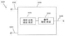
도 3은 본 발명의 실시예에 따른 자기 센서(1105)의 예시적 도면을 도시한다. 자기 센서(1105)는 하우징(도시 없음), 상기 하우징(도시 없음) 내에 있는 반도체 기판, 제1 입력 A1(1102), 제2 입력 A2(1104), 출력 포트 B(1106), 및 반도체 기판 상에 있는 전자 회로(1100)를 포함한다. 전자 회로(1100)는 제어 신호 생성 회로(1110) 및 제어 신호 생성 회로(1110)에 결합된 출력 제어 회로(1120)를 포함한다. 실시예에서, 제1 입력 A1(1102) 및 제2 입력 A2(1104)는 외부 전원에 직접 연결될 수 있다(예를 들면, 도 16에서 1610). 실시예에서, 제1 입력 A1(1102) 및 제2 입력 A2(1104)은 예를 들면 외부 부하를 통해 외부 전원에 직렬로 연결될 수 있다.FIG. 3 shows an exemplary view of a
제어 신호 생성 회로(1110)는 하나 이상의 신호를 검출하고, 검출된 하나 이상의 신호를 기초로 제어 신호를 생성하도록 구성될 수 있다. 일부 예에서, 하나 이상의 신호는 전기 배선 또는 케이블을 통해 수신된 하나 이상의 전기 신호일 수 있다. 일부 다른 예에서, 하나 이상의 신호는 자기 센서(1105)에 의해 무선으로 또는 다른 수단에 의해 수신된 하나 이상의 자기 신호 또는 다른 유형의 신호일 수 있다.The control
동작에서, 제어 신호 생성 회로(1110)는 하나 이상의 검출된 신호를 기초로 소정 조건이 만족되는지 여부를 결정한다. 하나 이상의 검출된 신호를 기초로 소정 조건이 만족되는 경우, 제어 신호 생성 회로(1110)는 제1 제어 신호를 생성하여 출력 제어 회로(1120)에 전송하고, 다음으로 이에 따라 자기 센서(1105)를 제1 상태에서 동작하도록 제어할 것이다. 제1 상태에서, 전기(부하) 전류는 자기 센서로부터 나와 출력 포트 B(1106)로 흐를 것이다. 제어 신호 생성 회로(1110)는 또한 제2 제어 신호를 생성하고 출력 제어 회로(1120)로 전송하여 자기 센서(1105)를 제2 상태에서 동작하도록 제어한다. 제2 상태에서, 전기(부하) 전류는 출력 포트 B(1106)로부터 나와서 자기 센서로 흐를 수 있다. 제어 신호 생성 회로에서 제1 상태 또는 제2 상태를 결정하는 방법이 더욱 상세히 설명된다.In operation, the control
반면에, 하나 이상의 검출된 신호를 기초로 소정 조건이 만족되지 않은 경우, 제어 신호 생성 회로(1110)는 제3 제어 신호를 생성하고 출력 제어 회로(1120)에 전송하여 자기 센서(1105)를 제3 상태에서 동작하도록 제어한다. 제3 상태에서, 전기(부하) 전류는 출력 포트 B(1106)를 통해 흐르지 않는다. 제3 상태에 있는 일부 상황에서, 소량의 전류만이 출력 포트 B(1106)를 통해 흐른다 즉, 전류의 세기는 전기(부하) 전류의 1/5 보다 적다.On the other hand, when a predetermined condition is not satisfied based on one or more detected signals, the control
일부 실시예에서, 출력 제어 회로(1120)는 제어 신호 생성 회로(1110)와 결합되고, 자기 센서(1105)를 제어 신호 생성 회로(1110)로부터 수신된 제어 신호를 기초로 결정된 상태에서 동작하도록 제어한다. 예를 들면, 출력 제어 회로(1120)가 제1 제어 신호를 수신하는 경우, 출력 제어 회로(1120)는 자기 센서(1105)를 전기(부하) 전류가 출력 포트 B(1106)로 흐르는 제1 상태에서 동작하도록 제어한다. 출력 제어 회로(1120)가 제2 제어 신호를 수신하는 경우, 출력 제어 회로(1120)는 자기 센서(1105)를 전기(부하) 전류가 외부로부터 출력 포트 B(1106)를 통해 자기 센서로 흐르는 제2 상태에서 동작하도록 제어한다. 출력 제어 회로(1120)가 제3 제어 신호를 수신하는 경우, 출력 제어 회로(1120)는 자기 센서(1105)를 전기(부하) 전류가 출력 포트 B(1106)를 통해 흐르지 않는(또는 전기(부하) 전류와 비교할 때 소량의 전류, 예를 들면 전기(부하) 전류의 1/4 보다 적은 전류만이 흐르는) 제3 상태에서 동작하도록 제어한다. 실시예에서, 출력 제어 회로(1120)는 제1 제어 신호 및 제2 제어 신호 등을 포함하는 복수개의 제어 신호를 교호로 수신할 수 있다. 따라서, 출력 제어 회로(1120)는 자기 센서(1105)를 상이한 상태 사이에서 교호로 동작하도록 제어할 수 있다. 구체적으로, 자기 센서(1150)는 제1 상태와 제2 상태 사이에서 교호로 동작할 수 있다. 실시예에서, 자기 센서(1105)는 제3 상태에서 동작하는 경우, 자기 센서(1105)는 제1 상태 또는 제2 상태에서 동작하는 것이 방지될 수 있다.In some embodiments, the
실시예에서, 제1 입력 A1(1102) 및 제2 입력 A2(1104)가 외부 AC 전원(1610)로 연결되는 경우(도 8), 제1 상태, 제2 상태, 또는 제3 상태에 있는 자기 센서(1105)의 동작 주파수는 외부 AC 전원(1610)의 주파수에 정비례하도록 설정될 수 있다. 실시예에서, 제3 상태에 있는 자기 센서(1105)의 동작 주파수는 외부 AC 전원(1610)의 주파수의 2배인, 제1 상태 또는 제2 상태의 동작 주파수의 2배이다.In an embodiment, when the
도 4는 본 발명의 상이한 실시예에 따른 자기 센서(1105)의 예시도이다. 이 실시예에서, 자기 센서(1105)는 제1 입력 A1(1102), 제2 입력 A2(1104), 출력 포트 B(1106), 및 전자 회로(1100)를 포함한다. 전자 회로(1100)는 자계 검출 회로(1130), 자계 검출 회로(1130)와 결합된 상태 제어 회로(1140), 및 상태 제어 회로(1140)와 결합된 출력 제어 회로(1120)를 포함한다.4 is an exemplary diagram of a
자계 검출 회로(1130)는 외부 자계를 검출하고 검출된 외부 자계에 따라 자기 유도 신호를 출력하도록 구성될 수 있다. 자기 유도 신호는 외부 자계의 극성 및 강도를 표시 또는 나타낼 수 있다.The magnetic
상태 제어 회로(1140)는 소정 조건이 만족되는지 여부를 결정하고, 또한 제어 신호의 수신시의 결정을 기초로 출력 제어 회로(1120)에 대응하는 제어 신호를 전송하도록 구성될 수 있으며, 출력 제어 회로(1120)는 자기 센서(1105)를 자기 유도 신호를 기초로 결정되는 대응하는 상태에서 동작하도록 제어할 수 있다. 구체적으로, 소정 조건이 만족되는 경우, 대응하는 상태는 제1 상태 및 제2 상태 중 하나일 수 있으며, 이는 각각이 자기 유도 신호에 의해 표시되는 외부 자계의 특정 극성에 대응한다. 예를 들면, 제1 상태는 외부 자계의 제1 극성이 검출되는 상황에 대응할 수 있으며, 제2 상태는 외부 자계의 제2 극성(제1 극성의 반대임)이 검출되는 상황에 대응할 수 있다. 따라서, 소정 조건이 만족되고 외부 자계가 제1 극성을 나타내는 경우, 상태 제어 회로(1140)는 이를 나타내는 제어 신호를 출력 제어 회로(1120)에 전송할 수 있으며, 이에 따라 출력 제어 회로(1120)는 자기 센서(1105)를 제1 상태에서 동작하도록 제어할 수 있다. 상술한 것처럼, 제1 상태에서, 전기(부하) 전류는 자기 센서로부터 출력 포트 B(1106)를 통해 외부로 흐른다. 소정 조건이 만족되고 외부 자계가 제1 극성의 반대인 제2 극성을 나타내는 경우, 상태 제어 회로(1140)는 이를 나타내는 제어 신호를 출력 제어 회로(1120)로 전송하고, 이를 기초로 출력 제어 회로(1120)는 자기 센서(1105)를 제2 상태에서 동작하도록 제어할 수 있다. 상술한 것처럼, 제2 상태에서, 전기(부하) 전류는 외부로부터 출력 포트 B(1106)를 통해 자기 센서로 흐른다.The
반면에, 상태 제어 회로(1140)가 소정 조건이 만족되지 않는 경우(또는 상태 제어 회로(1140)가 자기 유도 신호에 응답하지 않거나 자계 검출 회로(1130)로부터 자기 유도 신호를 획득할 수 없는 경우), 상태 제어 회로(1140)는 이를 나타내는 제어 신호를 출력 제어 회로(1120)에 전송하여 자기 센서(1105)를 제3 상태에서 동작하도록 제어할 수 있다. 제3 상태에서, 전기(부하) 전류가 출력 포트 B(1106)을 통해 흐르지 않는다(또는 전기(부하) 전류에 비해 소량의 전류만이 출력 포트 B를 통해 흐른다, 예를 들면 전류의 세기가 전기(부하) 전류의 1/4 보다 적다).On the other hand, if the
출력 제어 회로(1120)는 제어 신호 생성 회로(1110)와 결합되고, 자기 센서(1105)를 제어 신호 생성 회로(1110)로부터 수신된 제어 신호를 기초로 결정되는 상태에서 동작하도록 제어하도록 구성된다. 예를 들면, 출력 제어 회로(1120)가 소정 조건이 충족됨을 나타내는 제어 신호 및 외부 자계의 제1 극성을 수신하는 경우, 출력 제어 회로(1120)는 자기 센서(1105)를 제1 상태에서 동작하도록 제어하여, 전기(부하) 전류가 출력 포트 B(1106)를 통해 자기 센서 밖으로 흐르도록 한다. 출력 제어 회로(1120)가 소정 조건의 만족 및 외부 자계로부터 검출된 제2 극성을 나타내는 제어 신호를 수신하는 경우, 출력 제어 회로(1120)는 자기 센서(1105)를 제2 상태에서 동작하도록 제어하여, 전기(부하) 전류가 외부로부터 출력 포트 B(1106)를 통해 자기 센서로 흐르도록 한다. 출력 제어 회로(1120)가 소정 조건이 충족되지 않음을 나타내는 제어 신호를 수신하는 경우, 출력 제어 회로(1120)는 자기 센서(1105)를 제3 상태에서 동작하도록 제어하고, 여기서는 전기(부하) 전류가 출력 포트 B(1106)를 통해 흐르지 않는다(또는 전기(부하) 전류에 비해 소량의 전류가 출력 포트 B를 통해 흐른다 예를 들면, 전류는 전기(부하) 전류의 1/4 보다 적다). 실시예에서, 출력 제어 회로(1120)는 시간 내에 복수개의 제어 신호를 교호로 수신할 수 있다. 따라서, 출력 제어 회로(1120)는 자기 센서(1105)를 제1 상태와 제2 상태 사이를 포함하는 상이한 상태 중에서 동작하도록 제어한다.The
실시예에서, 출력 제어 회로(1120)는 사용자의 사양을 기초로 구성될 수 있다. 예를 들면, 출력 제어 회로(1120)는 자기 센서(1105)를 작업 상태와 고임피던스 상태 사이에서 교호로 동작하도록 제어하도록 구성될 수 있다. 작업 상태는 제1 상태 또는 제2 상태에 대응할 수 있으며, 고-임피던스 상태는 제3 상태에 대응할 수 있다.In an embodiment, the
도 5는 본 발명의 다른 실시예에 따른 자기 센서(1105)의 예시도를 도시한다. 이 실시예에서, 자계 검출 회로(1130)의 예시적 구조가 제공된다. 도 4와 유사한 전자 회로(1100)는 자계 검출 회로(1130), 상태 제어 회로(1140), 및 출력 제어 회로(1120)를 포함한다. 이 실시예에서 자계 검출 회로(1130)는 자기 감지 소자(1131), 신호 처리 소자(1132) 및 아날로그-디지털 변환 소자(1133)를 포함한다.5 shows an example of a
자기 감지 소자(1131)는 외부 자계에 관한 일정 정보를 나타내는 아날로그 전기 신호를 검출하고 신호 처리 소자에 출력하도록 구성될 수 있다. 예를 들면, 자기 감지 소자(1131)로부터의 신호의 출력은 외부 자계의 극성을 나타낼 수 있다. 실시예에서, 자기 감지 소자(1131)는 홀 보드(Hall Board)를 기초로 이행될 수 있다.The
신호 처리 소자(1132)는 자기 감시 소자(1131)로부터 아날로그 전기 신호를 처리하고 검출된 신호의 정확성을 개선하기 위하여 아날로그 전기 신호의 간섭을 증폭하고 줄임에 의해 처리된 아날로그 전기 신호를 생성하도록 구성될 수 있다. 처리된 아날로그 전기 신호는 아날로그-디지털 변환 소자(1133)로 전송된다.The
아날로그-디지털 변환 소자(1133)는 처리된 아날로그 전기 신호를 자기 유도 신호로 변환하도록 구성될 수 있다. 외부 자계의 극성만이 검출될 필요가 있는 상황에서, 자기 유도 신호는 스위칭 디지털 신호에 대응할 수 있다. 도 5에서의 상태 제어 회로(1140) 및 출력 제어 회로(1120)는 도 4에 대해 개시된 것과 유사한 방식으로 동작한다.The analog-to-
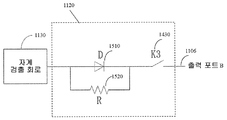
도 6은 본 발명의 실시예에 따른 출력 제어 회로(1120)의 예시적 이행을 도시한다. 실시예에서, 출력 제어 회로(1120)는 사용자의 사양에 따라 구성될 수 있다. 도 6에 도시된 것처럼, 출력 제어 회로(1120)는 제1 스위치 K1(1410), 제2 스위치 K2(1420), 및 제3 스위치 K3(1430)을 포함한다. 제1 스위치 K1(1410), 제2 스위치 K2(1420), 및 제3 스위치 K3(1430) 각각은 다이오드 또는 트랜지스터이다. 제1 스위치는 제3 스위치 K3(1430)를 통해 출력 포트 B(1106)과 결합되어 부하 전류가 제1 방향을 통해 흐르도록 하는 제1 전류 경로를 형성한다. 제2 스위치는 제3 스위치 K3(1430)를 통해 출력 포트 B(1106)와 결합되어, 부하 전류가 제1 방향의 반대인 제2 방향으로 흐르도록 하는 제2 전류 경로를 형성한다. 제1 스위치 K1(1410) 및 제2 스위치 K2(1420)는 자기 유도 신호(1405)에 응답하여 대응하는 전류 경로를 선택적으로 턴 온한다.6 illustrates an exemplary implementation of an
실시예에서, 제1 스위치 K1(1410) 및 제2 스위치 K2(1420)은 사용자의 사양에 따라 선택적으로 턴 온 또는 턴 오프될 수 있다. 실시예에서, 제1 스위치 K1(1410) 및 제2 스위치 K2(1420)는 외부 자계의 검출된 극성을 나타내는 자기 유도 신호(1405)를 수신하도록 구성될 수 있다. 제1 스위치 K1(1410) 및 제2 스위치 K2(1420)는 자기 유도 신호(1405)에 응답하여 선택적으로 턴 온 또는 턴 오프될 수 있다. 예를 들면, 제1 스위치 K1(1410)는 고전압 도전 스위치일 수 있으며, 제2 스위치 K2(1420)는 저전압 도전 스위치일 수 있다. 이를 성취하기 위하여, 제1 스위치 K1(1410)는 고전압 VDD(1407)(예를 들면, 직류 전원)에 연결되고, 제2 스위치 K2(1420)는 저전압(예를 들면, 접지)에 연결된다. 자기 유도 신호(1405)가 예를 들면 외부 자계로부터 검출된 제1 극성을 나타내는 고전압을 갖는 경우, 제1 스위치 K1(1410)는 턴 온 될 수 있고, 제2 스위치 K2(1420)는 턴 오프될 수 있다. 자기 유도 신호(1405)가 외부 자계의 제1 극성의 반대인 예를 들면 제2 극성을 나타내는 저전압을 갖는 경우, 제1 스위치 K1(1410)는 턴 오프될 수 있으며, 제2 스위치 K2(1420)는 턴 온될 수 있다.In an embodiment, the
실시예에서, 제3 스위치 K3(1430)는 자기 센서(1105)가 소정 조건을 만족하는지 여부를 기초로 턴 온 또는 턴 오프될 수 있다. 예를 들면, 자기 센서(1105)가 소정 조건을 만족하는 경우, 제3 스위치 K3(1430)는 턴 온될 수 있다. 그게 아니라면, 제3 스위치 K3(1430)는 턴 오프될 수 있다. 제3 스위치를 제어하는 방법에 대한 상세한 것은 도 10에 대해 설명된다.In an embodiment, the
상술한 것처럼, 자기 센서(1105)가 소정 조건을 만족하고 자기 유도 신호가 고전압을 갖는 경우, 제1 스위치 K1(1410)가 턴 온되고, 제2 스위치 K2(1420)가 턴 오프되며, 제3 스위치 K3(1430)가 턴 온된다. 따라서, 제1 전류 경로는 온이 되고, 제2 전류 경로는 오프가 된다. 결과적으로, 출력 제어 회로(1120)는 자기 센서(1105)를 제1 상태에서 동작하도록 제어한다. 즉, 전기(부하) 전류는 VDD(1407)로부터 제1 스위치 K1(1410), 제3 스위치 K3(1430)를 통과하고, 최종적으로 출력 포트 B(1106) 밖으로 흐른다.As described above, when the
자기 센서(1105)가 소정 조건을 만족하고 자기 유도 신호가 저전압을 갖는 경우, 제1 스위치 K1(1410)는 턴 오프되고, 제2 스위치 K2(1420)는 턴 온되고, 제3 스위치 K3(1430)가 턴 온된다. 따라서, 제1 전류 경로는 오프가 되고, 제2 전류 경로는 온이된다. 결과적으로, 출력 제어 회로(1120)는 자기 센서(1105)를 제2 상태에서 동작하도록 제어할 수 있다. 즉, 전기(부하) 전류는 출력 포트 B(1106)로 들어가서 제3 스위치 K3(1430), 제2 스위치 K2(1420)를 통해 접지로 흐른다.When the
자기 센서(1105)가 소정 조건을 만족하지 않는 경우, 제3 스위치 K3(1430)는 턴 오프된다. 따라서, 제1 전류 경로와 제2 전류 경로 모두가 온이 되지 않는다. 결과적으로, 출력 제어 회로(1120)는 자기 유도 신호(1405)가 고전압이거나 저전압이거나 상관없이 자기 센서(1105)를 제3 상태에서 동작하도록 제어할 수 있다. 즉, 전기(부하) 전류가 출력 포트 B(1106)를 통해 흐르지 않는다(또는 상술한 전기(부하) 전류와 비교할 때 소량의 전류만이 출력 포트 B를 통해 흐른다 예를 들면, 전류는 전기(부하) 전류의 1/4 보다 적고, 자기 센서 외부의 부하를 구동할 수 없다). 따라서, 출력 제어 회로(1120)는 자기 유도 신호(1405)에 응답하지 않는다.When the
도 7은 본 발명의 다른 실시예에 따른 출력 제어 회로(1120)의 예시적 이행을 도시한다. 도시된 것처럼, 출력 제어 회로(1120)는 자계 검출 회로(1130)과 결합된다. 출력 제어 회로(1120)는 자계 검출 회로(1130)로부터 자기 유도 신호(1405)(도 6에 도시된 것처럼)를 수신한다. 출력 제어 회로(1120)는 단일 도전 스위치 D(1510), 저항 R(1520), 및 제3 스위치 K3(1430)를 포함한다. 단일 도전 스위치 D(1510)는 제3 스위치 K3(1430)를 통해 출력 포트 B(1106)과 결합되고, 부하 전류가 제1 방향으로 흐르도록 허용하는 제1 전류 경로를 형성한다. 반면에, 저항 R(1520)은 제3 스위치 K3(1430)를 통해 출력 포트 B(1106)와 결합되어, 부하 전류가 제1 방향의 반대인 제2 방향으로 흐르도록 허용하는 제2 전류 경로를 형성한다. 자기 센서(1105)가 소정 조건을 만족하는 경우, 제3 스위치 K3(1430)는 턴 온될 수 있다. 아니라면, 제3 스위치 K3(1430)는 턴 오프될 수 있다. 제3 스위치의 온/오프 제어 방법에 대한 상세한 것이 도 10에 대해서 설명된다. 단일 도전 스위치 D(1510)는 자계 검출 회로(1130)로부터 수신된 자기 유도 신호(1405)를 기초로 선택적으로 턴 온 또는 오프될 수 있다. 예를 들면, 자기 유도 신호(1405)가 고전압을 갖는 경우, 단일-도전 스위치 D(1510)가 턴 온된다. 자기 유도 신호(1405)가 저전압을 갖는 경우, 단일-도전 스위치 D(1510)는 턴 오프된다. 다른 실시예에서, 저항 R(1520)은 단일-도전 스위치 D(1510)와 역병렬 연결된 다른 단일-도전 스위치에 의해 대체될 수 있다.FIG. 7 illustrates an exemplary implementation of an
전술한 것처럼, 자기 센서(1105)가 소정 조건을 만족하고 자계 검출 회로(1130)로부터 수신된 자기 유도 신호(1405)가 고전압을 갖는 경우, 단일-도전 스위치 D(1510) 및 제3 스위치 K3(1430) 모두 턴 온된다. 따라서, 제1 전류 경로는 온이되고, 제2 전류 경로는 오프가 된다. 결과적으로, 출력 제어 회로(1120)는 자기 센서(1105)를 제1 상태에서 동작하도록 제어할 수 있다. 즉, 전기(부하) 전류는 출력 포트 B(1106)로부터 나와서 단일-도전 스위치 D(1510) 및 제3 스위치 K3(1430)을 통해 흐른다.As described above, when the
자기 센서(1105)가 소정 조건을 만족하고 자계 검출 회로(1130)로부터 수신된 자기 유도 신호(1405)가 저전압을 갖는 경우, 단일-도전 스위치 D(1510)는 턴 오프되고, 제3 스위치 K3(1430)는 턴 온된다. 따라서, 제1 전류 경로는 오프가 된다. 자기 유도 신호가 낮고, 제3 스위치 K3(1430)가 온이므로, 제2 전류 경로가 도전된다. 결과적으로, 출력 제어 회로(1120)는 자기 센서(1105)를 제2 상태에서 동작하도록 제어할 수 있다. 즉, 전기(부하) 전류는 출력 포트 B(1106)로 들어가고 각각 제3 스위치 K3(1430) 및 저항 R(1520)을 통해 흐른다.When the
자기 센서(1105)가 소정 조건을 만족하는 않는 경우, 제3 스위치 K3(1430)는 턴 오프된다. 이 경우, 제1 전류 경로와 제2 전류 경로 모두 온되지 않는다. 결과적으로, 출력 제어 회로(1120)는 자기 센서(1105)를 자기 유도 신호(1405)가 고전압 또는 저전압을 가지는 여부와 상관없이 제3 상태에서 동작하도록 제어할 수 있다. 즉, 전기(부하) 전류가 출력 포트 B(1106)를 통해 흐르지 않는다. 따라서, 출력 제어 회로(1120)는 자기 유도 신호(1405)에 응답하지 않는다.When the
도 8은 본 발명의 다른 실시예에 따른 자기 센서(1105)의 다른 예시적 도면을 도시한다. 도시된 것처럼, 자기 센서(1105)의 입력(1615)은 외부 AC 전원(1610)에 연결된다. 이 실시예에서, 자기 센서(1105)는 입력(1615)에 연결된 정류기(1150)를 포함하고, 외부 AC 전원(1610)로부터 한 쌍의 차동 AC 신호를 수신하고, 한 쌍의 차동 AC 신호를 직류(DC) 신호로 변환하도록 구성된다. 정류기(1150)의 출력 전압은 자계 검출 회로(1130), 상태 제어 회로(1140), 및 출력 제어 회로(1120)에 파워 업(power up)하는데 이용될 수 있다. 자기 센서(1105)는 전술한 것처럼 자계 검출 회로(1130), 상태 제어 회로(1140), 및 출력 제어 회로(1120)를 더 포함할 수 있다.FIG. 8 shows another exemplary view of a
도 9는 본 발명의 실시예에 따른 정류기(1150)의 예시적 도면을 도시한다. 정류기(1150)는 전파 정류기 브리지 및 전파 정류기에 연결된 안정화 유닛을 포함한다. 전파 정류기 브리지는 제1 다이오드 D1(1710), 제2 다이오드 D2(1720), 제3 다이오드 D3(1730), 및 제4 다이오드 D4(1740)를 포함한다. 도 9에 도시된 것처럼, 제1 다이오드 D1(1710)는 제2 다이오드 D2(1720)에 직렬로 연결되고, 제3 다이오드 D3(1730)는 제4 다이오드 D4(1740)에 직렬로 연결된다. 제1 다이오드 D1(1710)의 출력 및 제2 다이오드 D2(1720)의 입력은 제1 입력 포트 VAC+(1705)에 연결되고, 제3 다이오드 D3(1730)의 출력 및 제4 다이오드 D4(1740)의 입력은 제2 입력 포트 VAC-(1707)에 연결된다. 실시예에서, 제1 입력 포트 VAC+(1705) 및 제2 입력 포트 VAC-(1707)는 한 쌍의 차동 AC 신호이다. 전파 정류기 브리지는 AC 전원(1610)에 의해 출력되는 한 쌍의 차동 AC 신호를 직류 신호로 변환하도록 구성될 수 있다. 안정화 유닛은 제너 다이오드 DZ(1750)일 수 있으며, 소정 범위 내에서 전파 정류기 브리지에 의해 출력되는 직류 신호를 안정화시키도록 구성된다. 안정화 유닛은 안정화된 DC 전압을 출력한다.9 illustrates an exemplary diagram of a
실시예에서, 제1 다이오드 D1(1710)의 입력은 제1 연결점에서 제3 다이오드 D3(1730)의 입력에 연결되어, 전파 정류기 브리지의 접지된 포트를 형성한다. 또한, 제2 다이오드 D2(1720)의 출력은 제2 연결점에서 제4 다이오드 D4(1740)의 출력에 연결되어, 전파 정류기 브리지의 출력 포트 VDD(1760)를 형성한다. 제너 다이오드 DZ(1750)는 제1 연결점과 제2 연결점 사이에 위치된다. 실시예에서, 출력 VDD(1760)는 출력 제어 회로(1120)와 직접적으로 연결될 수 있다.In an embodiment, the input of the
실시예에서, 제1 입력 포트 VAC+(1705) 및 제2 입력 포트 VAC-(1707)는 외부 AC 전원(1610)에 연결된다. 이 경우, 출력 제어 회로(1120)는 자기 유도 신호(1405)에 추가로 외부 AC 전원(1610)의 극성에 응답할 수 있다. In an embodiment, the first input port VAC + 1705 and the second input port VAC- 1707 are connected to an external
실시예에서, 자기 센서(1105)가 제1 상태, 제2 상태 또는 제3 상태에서 동작하는지가 자기 센서(1105)가 소정 조건을 만족하는지 여부에 의존하며, 이는 사용자의 사양에 따라 결정될 수 있다. 따라서, 출력 제어 회로(1120)는 자기 센서(1105)를 전기(부하) 전류가 출력 포트 B(1106)로부터 나와 흐를 수 있는 제1 상태에서 또는 전기(부하) 전류가 출력 포트 B(1106)로 흐를 수 있는 제2 상태에서 동작하도록 제어할 수 있다. 다르게 또는 추가적으로는, 자기 센서(1105)가 소정 조건을 만족하는 경우, 출력 제어 회로(1120)는 자기 센서(1105)를 외부 AC 전원(1610)의 극성 및 자기 유도 신호(1405)에 의해 표시되는 자계의 극성에 응답하여 제1 상태와 제2 상태 사이에서 교호로 동작하도록 제어할 수 있다. 자기 센서(1105)가 소정 조건을 만족하지 않는 경우, 출력 제어 회로(1120)는 자기 센서(1105)를 전기(부하) 전류가 출력 포트 B(1106)를 통해 흐르지 않거나 또는 상술한 전기(부하) 전류에 비해 출력 포트 B를 통해 소량의 전류만이 흐르는, 예를 들면 전류의 세기가 전기(부하) 전류의 1/4 보다 적은 제3 상태에서 동작하도록 제어할 수 있다.In an embodiment, whether the
실시예에서, 자기 센서(1105)가 소정의 조건을 만족하는 경우, 출력 제어 회로(1120)는 자기 유도 신호 및 외부 AC 전원(1610) 모두에 응답하여 자기 센서(1105)를 제1 상태 또는 제2 상태에서 동작하도록 제어한다. 예를 들면, 자기 센서(1105)가 소정 조건을 만족하고 자기 유도 신호(1405)가 외부 자계가 제1 자극을 가지고 외부 AC 전원(1610)이 제1 전극을 갖는 것을 나타내는 경우, 출력 제어 회로(1120)는 자기 센서(1105)를 제1 상태에서 동작하도록 제어할 수 있다. 다른 예에서, 자기 센서(1105)가 소정 조건을 만족하고, 자기 유도 신호(1405)가 외부 자계가 제1 자극의 반대인 제2 자극을 가지고 AC 전원(1610)이 제1 전극의 반대인 제2 전극을 갖는 것을 나타내는 경우, 출력 제어 회로(1120)는 자기 센서(1105)를 제2 상태에서 동작하도록 제어할 수 있다.The
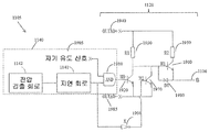
도 10은 본 발명의 다른 실시예에 따른 자기 센서(1105)의 예시도를 도시한다. 이 실시예에서, 상태 제어 회로(1140)의 예시적 구조가 제공된다. 도시된 것처럼, 자게 센서(1105)의 입력(1615)은 AC 전원(1610)에 연결된다. 이전에 도시된 것처럼, 자기 센서(1105)는 입력(1615)에 연결되고 외부 AC 전원(1610)으로부터 한 쌍의 차동 AC 신호를 수신하고 한 쌍의 차동 AC 신호를 직류 신호로 변환하도록 구성되는 정류기(1150)를 포함한다. 자기 센서(1105)는 자계 검출 회로(1130), 상태 제어 회로(1140) 및 출력 제어 회로(1120)를 더 포함한다. 도 10에 도시된 것처럼, 상태 제어 회로(1140)는 전압 검출 회로(1141), 지연 회로(1142), 및 로직 회로(1143)를 더 포함한다. 10 shows an exemplary view of a
전압 검출 회로(1142)는 자기 센서(1105) 내의 전압이 임계 전압과 동일하거나 또는 넘는지 여부를 검출하도록 구성될 수 있다. 전압이 임계 전압을 넘는 경우, 전압 검출 회로(1142)는 소정 트리거 신호를 생성하고 이를 지연 회로(1141)에 전송한다. 실시예에서, 전압은 자계 검출 회로(1130)의 공급 전압일 수 있다. 임계 전압은 자계 검출 회로(1130)의 자기 감지 소자(1131), 신호 처리 소자(1132) 및 아날로그-디지털 변환 소자(1133)의 동작에 필요한 최소 전압일 수 있다. 실시예에서, 임계 전압은 도 9에 대해 설명된 안정화 유닛에 의해 달성되는 안정화된 DC 전압 보다 작은 값으로 설정될 수 있다.
전압 검출 회로(1142)에 의해 트리거되면, 지연 회로(1141)는 자기 센서(1105)가 소정 조건을 만족하는지 여부를 결정한다. 구체적으로, 지연 유닛(1141)은 전압 검출 회로(1142)로부터 소정 트리거 신호를 수신하는 경우 계시를 시작할 것이다. 정해진 기간이 소정 길이의 기간에 같거나 또는 더 긴 경우, 지연 회로(1141)는 자기 센서(1105)가 소정 조건을 만족하는 것으로 결정한다. 아니라면, 지연 회로(1141)는 자기 센서(1105)가 소정 조건을 만족하지 않는 것으로 결정한다.When triggered by the
로직 회로(1143)는 출력 제어 회로(1120)가 자기 유도 신호에 응답하는 것을 가능하게 하고 자기 센서(1105)를 상술한 방식으로 3개의 상태 중 어느 하나에서 동작하도록 제어하도록 구성될 수 있다. 예를 들면, 자기 센서는 지연 회로(1141)에 의해 기록된 계시된 기간이 소정 기간과 같거나 큰 경우 제1 상태 또는 제2 상태에서 동작할 것이다. 로직 회로(1143)는 또한 지연 회로(1141)에 의해 기록된 계시된 기간이 소정 기간 보다 적을 경우에 출력 제어 회로(1120)가 자기 센서(1105)를 제3 상태에서 동작하도록 제어하는 것을 가능하게 하도록 구성된다.The
실시예에서, 자계 검출 회로(1130)의 공급 전압이 소정 전압 임계값에 도달하는 것을 검출하는 것은 자계 검출 회로(1130)의 전체 모듈 즉, 자기 감지 소자(1131), 신호 처리 소자(1132), 및 아날로그-디지털 변환 소자(1133)가 정상적으로 기능하는 것을 보장하는 것이다.The detection of the supply voltage of the magnetic
도 11은 본 발명의 다른 실시예에 따른 자기 센서(1105)의 일부의 회로의 예시적 이행을 도시한다. 구체적으로, 도 12는 출력 제어 회로(1120) 및 상태 제어 회로(1140)의 예시적 이행을 도시한다. 상태 제어 회로(1140)는 전압 검출 회로(1141), 지연 회로(1142), 및 도 11에 도시된 것과 같은 AND 게이트(1910)인 논리 회로(1143)을 포함한다. AND 게이트(1910)의 제1 입력은 자기 유도 신호(1905)에 대응하고, AND 게이트(1910)의 제2 입력은 지연 회로(1141)의 출력에 연결되고, AND 게이트(1910)의 출력은 출력 제어 회로(1120)에 연결될 수 있다.11 shows an exemplary implementation of a circuit of a portion of a
이 실시예에서, 출력 제어 회로(1120)는 3개의 고전압 도전 스위치(M0 1920, M1 1960, M2 1970), 다이오드 D5(1980), 인버터(1990), 제1 저항 R1(1930), 및 제2 저항 R2(1950)을 포함한다. 스위치 M0(1920)은 AND 게이트(1910)의 출력에 연결된다. 스위치 M0(1920)의 입력은 저항 R1(1930)을 통해 정류기(1150)의 전압 출력 포트 1940(OUTAD+)에 연결된다. 스위치 M2(1970)는 스위치 M0(1920)와 병렬로 결합된다. 스위치 M2(1970)의 제어 단자는 인버터(1990)를 통해 지연 회로(1141)의 출력에 연결된다. 실시예에서, 스위치 M2(1970)의 등가 저항은 스위치 M0(1920)의 것보다 더 크다.In this embodiment, the
동작에서, 지연 회로(1141)에 의해 기록된 계시된 기간이 소정 임계 기간과 같거나 더 긴 경우, 지연 회로(1141)는 고전압을 출력한다. 따라서, 이러한 고전압은 자계 검출 회로(1130)로부터의 자기 유도 신호(1905)가 AND 게이트(1910)를 통해 스위치 M0(1920)에 전송되도록 허용한다. 또한, AC 전원(1610)으로부터의 신호가 양의 절반 사이클에 있고 자계 검출 회로(1130)로부터의 자기 유도 신호(1905)가 저전압을 출력하는 경우, 스위치 M0(1920) 및 스위치 M2(1970)는 턴 오프될 수 있으며, 스위치 M1(1960)는 턴 온될 수 있다. 결과적으로, 전기(부하) 전류는 출력 포트 B(1106)로부터 나와 스위치 M1(1960)을 통해 흐를 수 있다. 즉, 출력 제어 회로(1120)는 자기 센서(1105)를 제1 상태에서 동작시킨다. 다르게는, AC 전원(1610)으로부터의 신호가 음의 절반 사이클에 있고 자계 검출 회로(1130)로부터의 자기 유도 신호(1905)가 고전압을 출력하는 경우, 스위치 M0(1920)는 턴 온 될 수 있고, 스위치 M1(1960) 및 스위치 M2(1970)는 턴 오프될 수 있다. 결과적으로, 전기(부하) 전류는 출력 포트 B(1106)로 들어가서 다이오드 D5(1980) 및 스위치 M0(1920)를 통과해서 흐를 수 있다. 즉, 출력 제어 회로(1120)는 자기 센서(1105)를 제2 상태에서 동작하도록 제어할 수 있다.In operation, if the period of time recorded by the
지연 회로(1141)에 의해 기록된 계시된 기간이 임계 기간 보다 짧은 경우, 지연 회로(1141) 및 AND 게이트(1910)는 저전압을 출력할 수 있고, 스위치 M0(1920) 및 M1은 턴 오프될 수 있고, 스위치 M2(1970)는 턴 온될 수 있다. 결과적으로, 전기 전류는 출력 포트 B(1106)로 들어가서 다이오드 D5(1980) 및 스위치 M2(1970)를 통해 흐른다. 스위치 M2(1970)의 등가 저항이 크므로, 전기 전류는 매우 작거나 또는 무시할 만하다. 즉, 출력 제어 회로(1120)는 자기 센서(1105)를 제3 상태에서 동작하도록 제어한다.The
도 12는 상태 제어 회로(1140)과 연결된 출력 제어 회로(1120)의 다른 실시예를 도시한다. 상태 제어 회로(1140)는 전압 검출 회로(1141), 지연 회로(1142), 및 로직 회로(1143)를 포함한다. 구체적으로, 상태 제어 회로(1140)의 로직 회로(1143)는 제1 신호 입력 포트(2002), 제2 신호 입력 포트(2004), 제1 신호 출력 포트(2006), 및 제2 신호 출력 포트(2008)를 포함한다. 제1 신호 입력 포트(2002)는 지연 회로(1141)의 출력에 연결될 수 있고, 제2 신호 입력 포트는 자기 유도 신호(2005)를 수신하도록 연결될 수 있다. 지연 회로(1141)에 의해 기록된 계시된 기간이 임계 기간 보다 짧은 경우, 로직 회로(1143)는 지연 회로(1141)에 저전압을 출력하도록 구성될 수 있다. 반면에, 지연 회로(1141)에 의해 기록된 계시된 기간이 임계 기간과 같거나 더 긴 경우, 지연 회로(1141)는 고전압을 출력할 수 있다. 또한, 로직 회로(1143)는 제1 신호 출력 포트(2006) 및 제2 신호 출력 포트(2008)를 통해 자기 유도 신호(2005)를 출력할 수 있다. 제1 신호 출력 포트(2006) 및 제2 신호 출력 포트(2006) 에서의 출력 신호는 180도 위상 편차를 가질 수 있다. 제1 출력 포트(2006) 및 제2 출력 포트(2008) 에서의 출력 신호는 동시에 고전압을 가질 수는 없다는 것이 이해되어야 한다.12 shows another embodiment of the
이 실시예에서, 출력 제어 회로(1120)는 3개의 스위치 즉, 스위치 M3(2060), M4(2040), M5(2070), 2개의 저항, 즉 저항 R3(2050), 및 저항 R4(2030), 보호 다이오드 D6(2020)를 포함한다. 구체적으로, 스위치 M3(2060) 및 M5(2070)은 둘 다 고전압 도전 스위치이고, 스위치 M4(2040)는 저전압 도전 스위치이다. 스위치 M3(2060) 및 스위치 M5(2070)의 제어 단자가 로직 회로(1143)의 제1 신호 출력 포트(2006) 및 제2 신호 출력 포트(2008)에 각각 연결된다. 스위치 M3(2060)의 입력은 저항 R3(2050)의 제1 포트에 연결된다. 스위치 M3(2060)의 출력은 정류기(1150)의 접지 출력 OUTAD- (2080)에 연결된다(도 7에 도시됨).In this embodiment, the
스위치 M4(2040)의 제어 단자는 저항 R3(2050)의 제2 포트에 연결된다. 스위치 M4(2040)의 입력은 정류기(1150)의 전압 출력 포트 OUTAD+(2010)에 연결된다. 스위치 M4(2040)의 출력은 스위치 M5(2070)의 입력에 연결된다. 스위치 M5(2070)의 출력은 정류기(1150)의 전압 출력 포트 OUTAD-(2080)에 연결된다. 실시예에서, 전압 출력 포트 OUTAD-(2080)는 플로팅 접지이다. 스위치 M4(2040)의 출력은 스위치 M5(2070)의 입력 및 출력 포트 B(1106)에 연결된다. 스위치 M4(2040)의 제어 단자는 보호 다이오드 D6(2020)의 양극에 연결된다. 스위치 M4(2040)의 입력은 보호 다이오드 D6(2020)의 음극에 연결된다. 저항 R4(2030)은 스위치 M4(2040)의 제어 단자와 입력 단자 사이에 연결된다.The control terminal of
동작에서, 지연 회로(1141)에 의해 기록된 계시된 기간이 임계 기간과 같거나 더 긴 경우, 지연 회로(1141)는 고전압을 출력한다. 이 경우, 로직 회로(1143)는 자기 유도 신호가 제1 신호 출력 포트(2006) 또는 제2 신호 출력 포트(2008)를 통해 출력되도록 허용한다. 제1 신호 출력 포트(2002) 및 제2 신호 출력 포트(2004)에서의 출력 신호는 180도의 위상 편차를 가질 수 있다. 또한, AC 전원(1610)으로부터의 신호가 양의 절반 사이클에 있고, 자계 검출 회로(1130)로부터의 자기 유도 신호(2005)가 고전압에 대응하는 경우, 스위치 M3(2060) 및 M4(2040)는 턴 온될 수 있고, 스위치 M5(2070)는 턴 오프될 수 있다. 결과적으로, 전기(부하) 전류는 출력 포트 B(1106)로 나와 스위치 M4(2040)를 통해 흐른다. 즉, 출력 제어 회로(1120)는 자기 센서(1105)를 제1 상태에서 동작하도록 제어한다. 다르게는, AC 전원(1610)으로부터의 신호가 음의 절반 사이클에 있고, 자계 검출 회로(1130)로부터의 자기 유도 신호(2005)가 저전압에 대응하는 경우, 스위치 M3(2060) 및 M4(2040)는 턴 오프될 수 있고, 스위치 M5(2070)는 턴 온될 수 있다. 결과적으로, 전기 전류는 출력 포트 B(1106)로 들어가서 스위치 M5(2070)를 통과해서 흐른다. 즉, 출력 제어 회로(1120)는 자기 센서(1105)를 제2 상태에서 동작하도록 제어한다.In operation, when the period of time recorded by the
지연 회로(1141)에 의해 기록된 계시된 기간이 임계 기간 보다 더 짧은 경우, 출력 제어 회로(1120)는 자기 센서(1105)를 제3 상태에서 동작하도록 제어하도록 지정된다. 이 경우, 지연 회로(1141)는 저전압을 출력하고, 로직 회로(1143)는 제1 출력 포트(2006) 및 제2 출력 포트(2008) 각각에서 저전압을 출력하며, 스위치 M3(2060), M4(2040), 및 M5(2070)는 턴 오프될 수 있다. 결과적으로, 출력 포트 B(1106)를 통해 전기 전류가 흐르지 않는다(또는, 전술한 전기(부하) 전류와 비교할 때 소량의 전류만이 출력 포트 B(1106)를 통해 흐른다, 즉 전류는 전기(부하) 전류의 1/4 보다 적다).The
도 13은 본 실시예에 따라 자기 센서(1105)에 의해 수행되는 신호 처리의 예시적 방법의 흐름도이다. 단계 S101에서, 외부 자계가 검출된다. 자기 유도 신호는 외부 자계의 극성 및/또는 강도가 생성됨을 나타낼 수 있다. 구체적으로, 단계 S101에서, 외부 자계와 관련된 아날로그 전기 신호 및 그와 관련된 정보가 검출되고 출력된다. 또한, 검출된 아날로그 전기 신호는 아날로그 전기 신호를 증폭하고 간섭을 감소함에 의해 처리될 수 있다. 또한, 처리된 아날로그 전기 신호는 자기 유도 신호를 생성하도록 변환될 수 있다. 일부 응용에서, 자기 유도 신호는 외부 자계의 극성을 나타내는 디지털 신호로 스위치될 수 있다.13 is a flowchart of an exemplary method of signal processing performed by the
단계 S102에서, 소정 조건이 만족되는지 여부가 결정된다. 소정 조건은 자기 센서의 특정 전압에 대해 관련되거나 또는 평가된다. 소정 조건이 만족되는 경우, 방법은 단계 S103으로 진행한다. 아니라면, 방법은 단계 S104로 진행한다. 구체적으로, 소정 조건은 자기 센서의 전압이 소정 전압 임계값에 도달하는 소정 기간으로서 설정될 수 있다. 실시예에서, 소정 조건이 만족되는지 여부가 자기 센서(1105)의 전압이 소정 전압 스래스홀드와 같거나 넘는 동안의 기간을 기초로 결정될 수 있다. 상술한 것처럼, 단계 S102를 수행하기 위하여, 자기 센서(1105)의 전압이 소정 전압 임계값에 도달하는지 여부가 결정된다. 그렇다면, 지연 회로(1142)는 계시를 시작한다. 기간이 소정 길이에 도달하는 경우, 소정 조건이 만족되는 것으로 결정된다. 아니라면, 소정 조건이 만족되지 않는 것으로 결정된다.In step S102, it is determined whether or not a predetermined condition is satisfied. The predetermined condition is related to or evaluated with respect to a specific voltage of the magnetic sensor. If the predetermined condition is satisfied, the method proceeds to step S103. If not, the method proceeds to step S104. Specifically, the predetermined condition may be set as a predetermined period in which the voltage of the magnetic sensor reaches a predetermined voltage threshold value. In an embodiment, whether or not a predetermined condition is satisfied can be determined based on a period during which the voltage of the
단계 S103에서, 자기 유도 신호를 기초로, 자기 센서는 제1 상태와 제2 상태 중 적어도 하나에서 동작하도록 제어된다. 여기에 설명되는 것처럼, 제1 상태에서, 전기(부하) 전류는 출력 포트 B(1106)로부터 나와서 흐른다. 제2 상태에서, 전기(부하) 전류는 출력 포트 B(1106)로 흐른다. 단계 S104에서, 자기 센서는 제3 상태에서 동작하도록 제어되며, 여기서 자기 센서(1105)는 제1 상태나 제2 상태에서 동작하지 않으며, 즉 전류는 출력 포트 B(1106)를 통해 흐르지 않는다(또는 무시할만하다).In step S103, based on the magnetic induction signal, the magnetic sensor is controlled to operate in at least one of the first state and the second state. As described herein, in the first state, electrical (load) current flows out of
도 14는 본 발명의 실시예에 따라, 여기에 설명된 자기 센서를 포함하는 모터 어셈블리(2200)의 예시도를 도시한다. 모터 어셈블리(2200)는 외부 AC 전원(1610)과 결합된 모터 M(1202), 모터 M(1202)와 직렬로 결합된 제어 가능한 양방향 AC 스위치(1300), 자기 센서(1105)를 포함한다. 자기 센서(1105)는 회전자 주위의 자계의 변이를 검출하기 위하여 모터(1202)의 회전자에 가까이 존재한다.Figure 14 illustrates an exemplary view of a
실시예에서, 자기 센서(1105)는 모터(1202)에 결합된 제1 입력(1102), 외부 AC 전원(1610)에 결합된 제2 입력(1104), 제어 가능한 양방향 AC 스위치(1105)의 출력 단자에 결합된 출력(1106)을 포함한다.In an embodiment,
실시예에서, 모터 어셈블리(2200)는 AC 전원(1610)을 기초로 얻어진 감소된 전압을 자기 센서(1105)에 제공하도록 구성된 전압 감소 회로(1200)를 더 포함할 수 있다. 이 실시예에서, 자기 센서(1105)의 제1 입력(1102)은 대신 전압 감소 회로(1200)에 결합된다.In an embodiment, the
도 15는 본 발명의 실시예에 따른 모터(2300)의 예시적 도면을 도시한다. 모터(2300)는 도 14에서의 모터(1202)와 유사하다. 실시예에서, 모터(2300)는 동기식 모터로서 고정자 및 고정자 주위를 감는 회전자(M1)을 포함한다. 고정자는 고정자 코어(M2) 및 고정자 코어(M2) 주위를 감는 단상 권선(M3)을 포함한다. 고정자 코어(M2)는 순철, 주철, 주강, 전기강, 실리콘강, 또는 다른 연자기 재료를 포함할 수 있다. 회전자(M1)는 영구 자석을 포함한다. 고정자 권선(M3)이 AC 전원(1610)과 직렬로 결합되는 경우, 회전자(M1)는 안정적 위상에서 60f/p rpm(회전/분)의 균일한 속도로 동작할 수 있으며, 여기서 f는 AC 전원(1610)의 주파수이고, p는 회전자(M1)의 극 쌍의 개수이다. 고정자 코어(M2)는 2개의 반대 극을 가지며, 그중 하나는 자극 호(pole arc)(예를 들면, M4, M5)를 갖는다. 회전자(M1)의 외면은 자극 호(예를 들면, M4, M5)에 반대이고, 이에 따라 외면과 자극 호 사이에 불균일한 갭을 형성한다. 고정자 극의 자극 호(예를 들면, M4, M5)는 오목한 홈을 구비한다. 오목한 홈을 제외한 자극 호의 부분은 회전자(M1)와 동일한 중심 축을 갖는다.15 shows an exemplary diagram of a
불균일 자계는 상술한 구성으로 형성될 수 있으며, 이는 회전자(M1)가 고정인 경우에 회전자(M1)의 극이 고정자 극의 중심 축에 대해 일정 각도로 관련됨을 보장한다. 각도는 자기 센서(1105)의 영향 하에서 모터(M)가 파워 업되는 때마다 회전자(M1)에 대한 초기 토크를 보장한다. 회전자(M1)의 극은 회전자(M1)의 대향 자극들 사이에서의 경계에 있을 수 있다. 고정자의 중심축은 고정자의 극의 중심을 통과하는 선일 수 있다. 실시예에서, 고정자 및 회전자(M1) 모두는 2개의 자극을 갖는다. 실시예에서, 고정자 및 회전자(M1)는 큰 개수의 자극 예를 들면 4개 또는 6개의 자극을 가질 수 있다.The non-uniform magnetic field can be formed in the above-described configuration, which ensures that the poles of the rotor M1 are related at an angle to the center axis of the stator poles when the rotor M1 is stationary. The angle ensures the initial torque for the rotor M1 every time the motor M is powered up under the influence of the
도 14를 참조로, 자기 센서(1105)가 소정 조건을 만족하는 경우, 자기 센서(1105)는 AC 전원(1610)으로부터의 신호 및 영구 자석 회전자(M1)의 극성에 의존하여 제1 상태 또는 제2 상태에서 동작할 수 있다. 구체적으로, AC 전원(1610)으로부터의 신호가 양의 절반 사이클에 있고 자계 검출 회로(1130)가 영구 자석 회전자(M1)가 제1 극성을 갖는 것을 검출한 경우, 출력 제어 회로(1120)는 자기 센서(1105)를 제1 상태에서 동작하도록 제어한다. 즉, 전기 전류는 자기 센서(1105)로부터 제어 가능한 양방향 AC 스위치(1300)로 흐를 수 있다. 다르게는, AC 전원(1610)으로부터의 신호가 음의 절반 사이클에 있고 자계 검출 회로(1130)가 영구 자석 회전자(M1)가 제1 극성의 반대인 제2 극성을 갖는 것을 검출한 경우, 출력 제어 회로(1120)는 자기 센서(1105)를 제2 상태에서 동작하도록 제어하며, 여기서 전기 전류는 제어 가능한 양방향 AC 스위치(1300)로부터 자기 센서(1105)로 흐를 수 있다.14, when the
자기 센서(1105)가 소정 조건을 만족하지 않는 경우, 자기 센서(1105)는 제3 상태에서 동작하며, 여기서 제어 가능한 양방향 AC 스위치(1300)와 자기 센서(1105) 사이에는 전기 전류가 흐르지 않는다(또는 제어 가능한 양방향 AC 스위치(1300)와 자기 센서(1105) 사이에 소량의 전류만이 흐른다).When the
실시예에서, 자기 센서(1105)는 도 9에 도시된 것처럼 정류기(1150) 및 도 6에 도시된 것처럼 출력 제어 회로(1120)를 포함한다. 상술한 것처럼, 도 6에서, 출력 제어 회로(1120)는 고전압 도전 스위치인 제1 스위치 K1(1410), 저전압 도전 스위치인 제2 스위치 K2(1420), 및 제3 스위치 K3(1430)를 포함한다. 소정 조건이 만족되는 경우, 제3 스위치 K3(1430)는 턴 온된다. 또한, AC 전원(1610)으로부터의 신호가 양의 절반 사이클 내에 있고 자기 유도 신호가 고전압인 경우, 제1 스위치 K1(1410)는 턴 온되고 제2 스위치 K2(1420)는 턴 오프된다. 결과적으로, 자기 센서(1105)는 제1 상태에서 동작하고, 여기서 전기 전류는 AC 전원(1610)으로부터 모터 M(1202), 전압 감소 회로(1105), 자기 센서(1105)의 제1 입력 포트, 전파 정류기 브리지 내의 제2 다이오드(D2)의 전압 출력 포트, 출력 제어 회로(1120)의 제1 스위치 K1(1410), 출력 포트 B(1106), 다음으로 제어 가능한 양방향 AC 스위치(1105)를 통해 흐르고 마지막으로 AC 전원(1610)으로 돌아간다. 다르게는, AC 전원(1610)으로부터의 신호가 음의 절반 사이클에 있고 자기 유도 신호가 저전압인 경우, 제1 스위치 K1(1410)는 턴 오프되고, 제2 스위치 K2(1420)는 턴 온된다. 결과적으로, 자기 센서(1105)는 제2 상태에서 동작하고, 여기서 전기 전류는 AC 전원(1610)으로부터 제어 가능한 양방향 AC 스위치(1105), 출력 포트 B(1106), 제2 스위치 K2(1420), 전파 정류기 브리지의 접지된 포트, 제1 다이오드 D1(1710), 자기 센서(1105)의 제1 입력 포트, 전압 감소 회로(1105), 모터(1202)를 통해 흐르고, 마지막으로 AC 전원(1610)으로 돌아간다.In an embodiment, the
AC 전원(1610)으로부터의 신호가 양의 절반 사이클에 있고 자계 검출 회로(1130)가 저전압을 출력하는 경우, 또는 AC 전원(1610)으로부터의 신호가 음의 절반 사이클에 있고 자계 검출 회로(1130)가 고전압을 출력하는 경우, 제1 스위치 K1(1410) 및 제2 스위치 K2(1420)는 턴 온될 수 없다. 그러므로, 출력 제어 회로(1120)는 제어 가능한 양방향 AC 스위치(1105)가 소정 방식으로 "온"과 "오프" 상태 사이에서 교대로 동작한다. 출력 제어 회로(1120)는 AC 전원(1610)의 극성 및 자기 검출 정보의 변이를 기초로 자기 센서(1105)가 고정자 권선(M3)을 파워 업하는 방식을 제어하여, 고정자에 의해 생성된 변하는 자계가 회전자를 따라 회전자의 자계의 위치에 따른 단일 방향으로 회전하도록 한다. 이는 회전자(M1)가 모터(1202)가 파워 업 할 때마다 고정된 방향으로 회전하는 것을 가능하게 한다.When the signal from the
반면에, 자기 센서(1105)가 소정 조건을 만족하지 않는 경우, 제3 스위치 K3(1430)는 턴 오프된다. 결과적으로, 자기 센서(1105)는 제3 상태에서 동작하고, 여기서 모터 어셈블리(2200) 내에 전기 전류가 흐르지 않는다(또는 상술한 전기 전류에 비교하여 소량의 무시할만한 전류가 모터 어셈블리(2200) 내로 흐른다 즉, 전류의 세기는 전기 전류의 1/4 보다 적다).On the other hand, when the
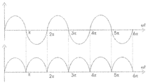
도 16은 본 발명의 실시예에 따라 각각 AC 전원(1610) 및 정류기 브리지(1150)로부터의 출력 전압의 파형을 도시한다. 구체적으로, 도 16의 상위부는 AC 전원(1610)의 출력 전압의 파형을 도시하고, 도 24의 하위부는 정류기 브리지(1150)의 출력 전압의 파형을 도시한다. 도시된 것처럼, 정류기 브리지의 출력 전압의 주파수는 AC 전원(1610)의 주파수의 2배이다.16 shows waveforms of output voltages from an
정류기 브리지(1150)의 출력 전압의 파형이 상승하는 경우, 출력 제어 회로(1120)는 출력 제어 회로(1120)가 제1 상태 또는 제2 상태에서 동작하기 이전에 제3 상태에서 동작할 수 있다. 따라서, AC 전원(1610)의 출력 전압의 파형이 양의 절반 사이클에 있는 경우, 자기 센서(1105)는 제1 상태에서 동작할 수 있다. AC 전원(1610)의 출력 전압의 파형이 음의 절반 사이클에 있는 경우, 자기 센서(1105)는 제2 상태에서 동작할 수 있다. 그러므로, 제3 상태의 동작 주파수는 제1 상태 또는 제2 상태의 동작 주파수에 정비례하고, 또한 AC 전원(1610)의 전압의 주파수에 비례한다. 실시예에서, 제3 상태의 동작 주파수는 AC 전원(1610)의 주파수의 2배인 제1 상태 또는 제2 상태의 동작 주파수의 2배이다.When the waveform of the output voltage of the
상술한 실시예는 단지 설명을 목적으로 한 것으로 이해되어야 한다. 본 발명은 제한적인 것을 의도하지 않는다. 자기 센서(1105)는 상술한 것과 같은 모터 어셈블리(2200) 외의 다른 응용에 이용될 수 있다.It should be understood that the above-described embodiments are for illustrative purposes only. The invention is not intended to be limiting. The
당업자라면 본 발명이 각종 개조 및/또는 강화를 받아들임을 인식할 것이다. 예를 들면, 상술한 다양한 구성 요소의 이행이 하드웨어 디바이스에서 내장될 수 있지만, 소프트웨어만의 해법, 예를 들면 기존 서버 상에 설치로서 이행될 수 있다. 또한, 여기에 설명되는 호스트 및 클라이언트 노드의 유닛은 펌웨어, 펌웨어/소프트웨어 조합, 펌웨어/하드웨어 조합, 또는 하드웨어/펌웨어/소프트웨어 조합으로 이행될 수 있다. 다른 실시예에서, 모터 및 제어 가능한 양방향 AC 스위치는 서로에 대해 직렬로 결합될 수 있으며, 제1 브랜치를 형성한다. 직렬-연결된 전압 감소 회로 및 자기 센서는 제2 브랜치를 형성한다. 제1 브랜치는 외부 AC 전원의 두 단부 사이에서 제2 브랜치와 병렬로 결합된다.Those skilled in the art will recognize that the present invention is susceptible to various modifications and / or enhancements. For example, the transition of the various components described above may be embodied in a hardware device, but may be implemented as a software-only solution, for example as an installation on an existing server. Also, the units of the host and client nodes described herein may be implemented as firmware, firmware / software combination, firmware / hardware combination, or hardware / firmware / software combination. In another embodiment, the motor and the controllable bidirectional AC switch may be coupled in series with respect to each other to form a first branch. The series-connected voltage reduction circuit and the magnetic sensor form a second branch. The first branch is coupled in parallel with the second branch between the two ends of the external AC power source.
전술한 것들이 최적 모드 및/또는 다른 예가 되는 것을 간주하여 설명되는 동안, 각종 변경이 가능할 수 있으며, 여기에 개시된 요지는 각종 형태 및 예로 이행될 수 있으며, 본 발명은 다수의 어플리케이션에서 적용될 수 있으며, 이들 중 일부만이 여기에 설명된다. 이하의 청구범위 및 전체 어플리케이션에 의해 본 발명의 진정함 범위 내에 있는 개조 및 변형이 의도된다.While various embodiments of the present invention have been shown and described, it will be apparent to those skilled in the art that various changes and modifications may be made without departing from the spirit and scope of the present invention as defined by the following claims. Only some of which are described herein. Modifications and variations that fall within the true scope of the invention are intended by the following claims and the entire application.
Claims (10)
하우징:
입력 포트 및 출력 포트 - 상기 입력 포트 및 상기 출력 포트 둘다 상기 하우징으로부터 연장하며, 상기 입력 포트는 외부 교류(AC) 전원에 연결됨 - ; 및
전기 회로를 포함하되,
상기 전기 회로는,
외부 자계를 검출하고 상기 외부 자계의 적어도 하나의 특성을 나타내는 자기 유도 신호를 출력하도록 구성되는 자계 검출 회로; 및
상기 출력 포트와 결합되고, 소정 조건이 만족될 때 제1 상태 및 제2 상태 중 적어도 하나에서 동작하도록 상기 자기 센서를 제어하고,
상기 제1 상태에서, 부하 전류는 상기 출력 포트로부터 상기 자기 센서의 외부로 제1 방향으로 흐르며,
상기 제2 상태에서, 상기 부하 전류는 상기 자기 센서의 외부로부터 상기 출력 포트를 통해 상기 자기 센서로 제1 방향의 반대인 제2 방향으로 흐르며,
소정 조건이 만족되지 않을 때, 제3 상태에서 동작하도록 상기 자기 센서를 제어하도록 구성되는 출력 제어 회로를 포함하고,
상기 자기 센서의 동작 주파수는 외부 AC 전원의 주파수에 정비례하는, 자기 센서.As a magnetic sensor:
housing:
An input port and an output port, both the input port and the output port extending from the housing, the input port being connected to an external AC power source; And
Electrical circuitry,
Wherein the electric circuit comprises:
A magnetic field detection circuit configured to detect an external magnetic field and output a magnetic induction signal indicative of at least one characteristic of the external magnetic field; And
A magnetic sensor coupled to the output port and controlling the magnetic sensor to operate in at least one of a first state and a second state when a predetermined condition is satisfied,
In the first state, a load current flows from the output port to the outside of the magnetic sensor in a first direction,
In the second state, the load current flows from the outside of the magnetic sensor to the magnetic sensor through the output port in a second direction opposite to the first direction,
And an output control circuit configured to control the magnetic sensor to operate in a third state when a predetermined condition is not satisfied,
Wherein the operating frequency of the magnetic sensor is directly proportional to the frequency of the external AC power source.
상기 자기 유도 신호가 상기 외부 자계가 제1 자극을 가지며, 상기 외부 AC 전원이 제1 극성을 가지는 것을 나타내는 경우에 부하 전류가 제1 방향으로 흐르도록 허용함에 의해 상기 자기 센서를 제1 상태에서 동작하도록 제어하도록 하고;
상기 자기 유도 신호가 상기 외부 자계가 제1 자극에 반대인 제2 자극을 가지며, 상기 외부 AC 전원이 제1 극성에 반대인 제2 극성을 가지는 것을 나타내는 경우에 부하 전류가 제2 방향으로 흐르도록 허용함에 의해 상기 자기 센서를 제2 상태에서 동작하도록 제어하도록 구성되는, 자기 센서.2. The output control circuit according to claim 1, wherein when the predetermined condition is satisfied,
Wherein the magnetic induction signal causes the magnetic sensor to operate in a first state by allowing the load current to flow in a first direction when the external magnetic field has a first magnetic pole and the external AC power source has a first polarity, ;
Wherein the magnetic induction signal causes the load current to flow in the second direction when the external magnetic field has a second magnetic pole opposite to the first magnetic pole and the external AC power source has a second polarity opposite to the first polarity And to control the magnetic sensor to operate in the second state by allowing the magnetic sensor to operate in the second state.
상기 전기 회로는 상기 외부 AC 전원에 대한 전파(full wave) 정류를 수행하도록 구성되는 정류기를 더 포함하고;
상기 제3 상태의 상기 자기 센서의 동작 주파수는 상기 정류기의 출력 전압의 주파수와 동일한, 자기 센서.The method according to claim 1,
Wherein the electrical circuit further comprises a rectifier configured to perform full wave rectification for the external AC power source;
And the operating frequency of the magnetic sensor in the third state is equal to the frequency of the output voltage of the rectifier.
특정 전압을 검출하고, 상기 특정 전압이 소정 전압 스래스홀드와 같거나 더 큰 경우에, 트리거링 신호를 출력하도록 구성되는 전압 검출 회로;
상기 트리거링 신호 수신시에, 상기 특정 전압이 소정 전압 스래스홀드와 같거나 더 큰 동안의 시간의 길이를 계시하도록 구성되는 지연 회로; 및
상기 지연 회로와 결합되고,
상기 시간의 길이가 소정 시간의 길이를 초과하는 경우에 상기 소정 조건이 만족됨을 시그널하고,
상기 시간의 길이가 소정 시간의 길이를 초과하지 않는 경우에 상기 소정 조건이 만족되지 않음을 시그널하도록 구성되는 로직 회로를 더 포함하는, 자기 센서. The electric circuit according to any one of claims 1 to 6,
A voltage detection circuit configured to detect a specific voltage and output a triggering signal when the specified voltage is equal to or greater than a predetermined voltage threshold;
A delay circuit configured to, upon receipt of the triggering signal, to indicate a length of time during which the particular voltage is greater than or equal to a predetermined voltage slice; And
Coupled to the delay circuit,
Signaling that the predetermined condition is satisfied when the length of the time exceeds a predetermined length of time,
And a logic circuit configured to signal that the predetermined condition is not satisfied when the length of time does not exceed a predetermined length of time.
교류 (AC) 전원을 기초로 동작하도록 구성되는 모터;
상기 모터에 의해 생성된 자계를 검출하고 검출된 상기 자계를 기초로 결정된 동작 상태에서 동작하도록 구성되는 자기 센서; 및
상기 모터와 직렬로 결합되며, 상기 자기 센서의 동작 상태를 기초로 상기 모터를 제어하도록 구성되는 양방향 AC 스위치를 포함하고,
상기 자기 센서는:
입력 포트 및 출력 포트 - 상기 입력 포트는 상기 AC 전원에 결합되고 상기 출력 포트는 상기 양방향 AC 스위치의 제어 단자와 결합됨 - ; 및
전기 회로를 포함하고, 상기 전기 회로는:
검출된 상기 자계의 적어도 하나의 특성을 표시하는 자기 유도 신호에 적어도 반응하여, 소정 조건이 만족될 때 제1 상태 및 제2 상태 중 적어도 하나에서 동작하도록, 그리고 소정 조건이 만족되지 않을 때 제3 상태에서 동작하도록 상기 자기 센서를 제어하기 위해 구성되는 출력 제어 회로를 포함하고,
상기 제1 상태에서, 부하 전류는 상기 출력 포트로부터 상기 자기 센서의 외부로 제 1 방향으로 흐르고,
상기 제2 상태에서, 부하 전류는 상기 출력 포트를 통해 상기 자기 센서의 외부로부터 상기 자기 센서 내로 제 1 방향에 반대인 제 2 방향으로 흐르며,
상기 자기 센서의 동작 주파수는 상기 외부 AC 전원의 주파수에 정비례하는, 모터 어셈블리.As a motor assembly:
A motor configured to operate based on an alternating current (AC) power source;
A magnetic sensor configured to detect a magnetic field generated by the motor and to operate in an operating state determined based on the detected magnetic field; And
A bidirectional AC switch coupled in series with the motor and configured to control the motor based on an operating state of the magnetic sensor,
The magnetic sensor includes:
An input port and an output port, the input port being coupled to the AC power source and the output port being coupled to a control terminal of the bidirectional AC switch; And
An electric circuit, said electric circuit comprising:
At least one of the first state and the second state when the predetermined condition is satisfied, and to operate in at least one of the first state and the second state when at least one characteristic of the magnetic field is detected, And an output control circuit configured to control the magnetic sensor to operate in a state where the magnetic sensor
In the first state, a load current flows from the output port to the outside of the magnetic sensor in a first direction,
In the second state, a load current flows from the outside of the magnetic sensor through the output port into the magnetic sensor in a second direction opposite to the first direction,
Wherein the operating frequency of the magnetic sensor is directly proportional to the frequency of the external AC power source.
반도체 기판;
입력 포트 및 출력 포트 - 상기 입력 포트는 외부 교류 (AC) 전원과 결합됨 - ; 및
상기 반도체 기판상의 전기 회로를 포함하고, 상기 전기 회로는:
상기 출력 포트와 결합되고, 소정 조건이 만족될 때 부하 전류가 상기 출력 포트를 통해 흐르는 상태에서 동작하도록, 그리고 소정 조건이 만족되지 않을 때 다른 상태에서 동작하도록 상기 집적 회로를 제어하기 위해 검출 신호에 반응하도록 구성되는 출력 제어 회로를 포함하고,
상기 집적 회로의 동작 주파수는 상기 외부 AC 전원의 주파수에 정비례하는, 집적 회로.As an integrated circuit,
A semiconductor substrate;
An input port and an output port, the input port being coupled to an external AC power source; And
An electrical circuit on said semiconductor substrate, said electrical circuit comprising:
And a control circuit coupled to the output port and configured to control the integrated circuit to operate in a state where a load current flows through the output port when a predetermined condition is satisfied and to operate in another state when a predetermined condition is not satisfied, And an output control circuit configured to respond,
Wherein the operating frequency of the integrated circuit is directly proportional to the frequency of the external AC power source.
Applications Claiming Priority (6)
| Application Number | Priority Date | Filing Date | Title |
|---|---|---|---|
| CNPCT/CN2015/086422 | 2015-08-07 | ||
| PCT/CN2015/086422 WO2016019921A1 (en) | 2014-08-08 | 2015-08-07 | Motor assembly and integrated circuit for motor drive |
| CN201610203624.2 | 2016-04-01 | ||
| CN201610203624 | 2016-04-01 | ||
| CN201610392395.3A CN106443513A (en) | 2015-08-07 | 2016-06-02 | Integrated circuit, motor assembly and application device |
| CN201610392395.3 | 2016-06-02 |
Publications (1)
| Publication Number | Publication Date |
|---|---|
| KR20170017818A true KR20170017818A (en) | 2017-02-15 |
Family
ID=57853971
Family Applications (1)
| Application Number | Title | Priority Date | Filing Date |
|---|---|---|---|
| KR1020160100018A KR20170017818A (en) | 2015-08-07 | 2016-08-05 | Magnetic sensor, integrated circuit and motor assembly |
Country Status (5)
| Country | Link |
|---|---|
| JP (2) | JP2017075931A (en) |
| KR (1) | KR20170017818A (en) |
| BR (1) | BR102016018244A2 (en) |
| DE (1) | DE102016114495A1 (en) |
| TW (1) | TWM542232U (en) |
-
2016
- 2016-08-04 DE DE102016114495.9A patent/DE102016114495A1/en not_active Withdrawn
- 2016-08-05 KR KR1020160100018A patent/KR20170017818A/en unknown
- 2016-08-06 TW TW105211945U patent/TWM542232U/en not_active IP Right Cessation
- 2016-08-08 BR BR102016018244A patent/BR102016018244A2/en not_active Application Discontinuation
- 2016-08-08 JP JP2016155741A patent/JP2017075931A/en active Pending
- 2016-12-15 JP JP2016006004U patent/JP3209222U/en not_active Expired - Fee Related
Also Published As
| Publication number | Publication date |
|---|---|
| DE102016114495A1 (en) | 2017-02-09 |
| BR102016018244A2 (en) | 2017-02-14 |
| JP2017075931A (en) | 2017-04-20 |
| JP3209222U (en) | 2017-03-09 |
| TWM542232U (en) | 2017-05-21 |
Similar Documents
| Publication | Publication Date | Title |
|---|---|---|
| US10469005B2 (en) | Magnetic sensor and an integrated circuit | |
| US20180234041A1 (en) | Magnetic sensor and an integrated circuit | |
| US9696182B2 (en) | Magnetic sensor and an integrated circuit | |
| WO2019241048A1 (en) | Operational mode control of a motor | |
| US10763766B2 (en) | Magnetic sensor and an integrated circuit | |
| US10483830B2 (en) | Magnetic sensor integrated circuit and motor component | |
| US9692329B2 (en) | Magnetic sensor and an integrated circuit | |
| US9954469B2 (en) | Magnetic sensor and an integrated circuit | |
| EP3128661B1 (en) | Magnetic sensor, method for controlling an operating state thereof and motor assembly | |
| US10637374B2 (en) | Magnetic sensor integrated circuit, motor component and application apparatus | |
| JP2016111911A (en) | Motor drive device | |
| CN107342661B (en) | Magnetic sensor integrated circuit, motor assembly and application equipment | |
| KR20170017818A (en) | Magnetic sensor, integrated circuit and motor assembly | |
| KR20170017819A (en) | Magnetic sensor, motor assembly and integrated circuit | |
| JP2017053844A (en) | Magnetic sensor integrated circuit and motor assembly | |
| US20160352266A1 (en) | Magnetic sensor integrated circuit, motor assembly and application device | |
| JP3207073U (en) | Magnetic sensor integrated circuit and motor assembly | |
| JP3207074U (en) | Magnetic sensor integrated circuit and motor component | |
| JP3211962U (en) | Motor component and sensor integrated circuit | |
| WO2016084294A1 (en) | Motor drive device | |
| JP2017090438A (en) | Magnetic sensor integrated circuit and motor assembly |