KR20170016319A - Freely assemblable toy track - Google Patents
Freely assemblable toy track Download PDFInfo
- Publication number
- KR20170016319A KR20170016319A KR1020167028268A KR20167028268A KR20170016319A KR 20170016319 A KR20170016319 A KR 20170016319A KR 1020167028268 A KR1020167028268 A KR 1020167028268A KR 20167028268 A KR20167028268 A KR 20167028268A KR 20170016319 A KR20170016319 A KR 20170016319A
- Authority
- KR
- South Korea
- Prior art keywords
- frame
- frame member
- corner
- strip
- rail
- Prior art date
Links
Images


Classifications
-
- A—HUMAN NECESSITIES
- A63—SPORTS; GAMES; AMUSEMENTS
- A63H—TOYS, e.g. TOPS, DOLLS, HOOPS OR BUILDING BLOCKS
- A63H18/00—Highways or trackways for toys; Propulsion by special interaction between vehicle and track
- A63H18/02—Construction or arrangement of the trackway
-
- A—HUMAN NECESSITIES
- A63—SPORTS; GAMES; AMUSEMENTS
- A63H—TOYS, e.g. TOPS, DOLLS, HOOPS OR BUILDING BLOCKS
- A63H18/00—Highways or trackways for toys; Propulsion by special interaction between vehicle and track
- A63H18/02—Construction or arrangement of the trackway
- A63H18/028—Looping; Jumping; Tilt-track sections
-
- A—HUMAN NECESSITIES
- A63—SPORTS; GAMES; AMUSEMENTS
- A63H—TOYS, e.g. TOPS, DOLLS, HOOPS OR BUILDING BLOCKS
- A63H18/00—Highways or trackways for toys; Propulsion by special interaction between vehicle and track
- A63H18/02—Construction or arrangement of the trackway
- A63H18/04—Up-and-down-hill trackways
-
- A—HUMAN NECESSITIES
- A63—SPORTS; GAMES; AMUSEMENTS
- A63H—TOYS, e.g. TOPS, DOLLS, HOOPS OR BUILDING BLOCKS
- A63H18/00—Highways or trackways for toys; Propulsion by special interaction between vehicle and track
- A63H18/02—Construction or arrangement of the trackway
- A63H18/06—Construction or arrangement of the trackway designed to cause movement of a vehicle by alteration of the inclination of part of the trackway
Abstract
복수개의 가이드 레일과 연결부재를 포함하는 자유롭게 조립 가능한 완구 궤도에 있어서, 매 하나의 가이드 레일은 모두 좌우 두개의 독립된 스트립 레일(1)이고, 연결부재는 프레임형 부재(2)이며, 프레임형 부재(2)는 내부프레임 변에서의 상대적 위치에 스트립 레일의 단부가 연결되도록 하는 연결부재를 구비하고, 좌우 두개의 가이드 레일(1) 양단은 각각 두개의 프레임형 부재(2)의 연결부재에 연결되어 궤도면 중부가 비게되는 궤도체를 형성함으로써, 완구차의 좌우 바퀴가 꼭 알맞게 좌우 두개의 스트립 레일(1)에 놓이도록 하여 완구차가 궤도를 따라 주행하는 것을 실현하고, 또 완구차의 폭크기에 근거하여 대응되는 폭의 프레임형 부재(2)를 선택하여 스트립 레일(1)과 연결하며, 이로써 궤도의 폭을 넓히고 완구 궤도의 적용 범위를 효과적으로 향상시킨다.In a freely assemblable toy track including a plurality of guide rails and connecting members, each of the guide rails is a pair of independent left and right strip rails (1), the connecting member is a frame member (2) (2) has a connecting member for connecting the end portion of the strip rail to a relative position on the side of the inner frame, and both ends of the left and right guide rails (1) are connected to the connecting members of the two frame members The left and right wheels of the toy vehicle are appropriately placed on the two left and right strip rails 1 to realize the toy vehicle traveling along the trajectory, The width of the frame member 2 is selected and connected to the strip rail 1, thereby widening the width of the orbit and effectively applying the range of the toy track Then phase.
Description
본 발명은 완구 궤도에 관한 것으로, 구체적으로 자유롭게 조립 가능한 완구 궤도에 관한 것이다.The present invention relates to a toy track, specifically to a freely assemblable toy track.
완구 궤도는 이미 오랜시간 유행되어 왔다. 최초의 궤도는 전체적인 궤도체로서 이러한 완구 궤도에 대하여 그 어떠한 변화도 행할 수 없어 플레이어는 단지 생산업체에서 설정한 방식에 따라 놀이를 할 수 밖에 없다. 이러한 완구 궤도는 플레이어가 완구궤도에 대하여 쉽게 질리는 것을 불러일으키도록 하여 플레이어의 조작능력 및 지력개발의 향상에 불리하다. 기존의 일부 완구 궤도는 복수개의 궤도구간으로 구성되고, 각 궤도구간의 전후단에 모두 다른 하나의 궤도구간과 결합되는 연결구조가 구비되는 바, 이러한 연결구조를 통하여 궤도구간을 완구차가 궤도구간을 따라 주행되도록 하는 하나의 경로로 조립한다. 그러나, 이러한 완구 조립 궤도는 단지 평면적인 궤도체로만 조립될 뿐, 입체 궤도로 조립될 수 없어 흥미성이 떨어진다. 또한, 기존의 완구 궤도에는 모두 완구차가 주행되도록 하는 궤도면과 완구차가 궤도면을 이탈하는 것을 방지하기 위한 리브가 포함되어 있다. 이러한 설계는 완구 궤도의 사용재료를 대폭 증가시켜 당해 완구의 원가를 높히고, 또한 궤도면의 폭도 궤도 자체의 한정을 받아 다른 사이즈 크기의 완구차 주행에 적용될 수 없다.The toy track has already been in fashion for a long time. The first orbit is a whole orbital, which can not make any changes to these toy tracks, and the player can only play according to the method set by the manufacturer. Such a toy track causes the player to easily get tired of the toy track, which is disadvantageous for improvement of the player's manipulation ability and intelligence development. The existing toy track is composed of a plurality of track sections, and each of the front and rear ends of each track section is provided with a coupling structure which is coupled with another one of the track sections. Through this coupling structure, the toy section is divided into the orbit section And assembled into one path to be driven along. However, such toy assembling trajectories are assembled only in planar orbits, and can not be assembled into three-dimensional orbits, which is less interesting. In addition, the existing toy track includes an orbit surface for allowing the toy vehicle to run, and a rib for preventing the toy vehicle from deviating from the raceway surface. Such a design greatly increases the cost of the toys by significantly increasing the materials used in the toy track, and can not be applied to toy car travels of different sizes, due to the limitation of the track orbit of the track plane itself.
상기 기존 기술에 따른 문제점에 대하여, 본 발명의 목적은 가격대 성능비가 높고 적용성이 강하며 조립 자유도가 높은 조립 가능한 완구 궤도를 제공하는 것이다. It is an object of the present invention to provide an assembled toy track having a high price performance ratio, high applicability, and high assembly freedom.
상기 목적을 달성하기 위하여, 본 발명에 사용된 기술적 해결방법은 다음과 같다. In order to achieve the above object, the technical solution used in the present invention is as follows.
복수개의 가이드 레일과 연결부재를 포함하는 자유롭게 조립 가능한 완구 궤도에 있어서, 상기 매 하나의 가이드 레일은 모두 좌우 두개의 독립된 스트립 레일이고, 상기 연결부재는 프레임형 부재이며, 상기 프레임형 부재는 내부프레임 변에서의 상대적 위치에 스트립 레일의 단부가 연결되도록 하는 연결부재를 구비하고, 전후 두 구간의 가이드 레일 사이는 프레임형 부재를 통하여 연결되어 궤도면 중부가 비게되는 궤도체를 형성하는 것을 특징으로 한다. Wherein each of the guide rails is a left and right two independent strip rails, the connecting member is a frame member, the frame member is a frame member, And a connecting member for connecting the end portion of the strip rail to a relative position on the side of the guide rails, wherein the guide rail between the two front and rear sections is connected via a frame member to form an orbital member in which the center of the orbital plane is hollow .
그 중, 상기 스트립 레일은 단면이 "L"형을 나타내는 스트립 레일이고, 상기 프레임형 부재는 사각형 프레임체 또는 "![]()
![]()
본 발명의 연결부재는 다음과 같은 것일 수 있다. The connecting member of the present invention may be as follows.
상기 프레임형 부재의 연결부재는 내부프레임 코너 위치의 서로 인접한 두개의 내부프레임 변에 개설되는 오목홈이고, 상기 스트립 레일의 양단부에는 외측으로 돌출되는, 오목홈 중에 삽입 연결되는 돌출 스트립이 대응되게 구비되는 것이거나; 또는 상기 프레임형 부재의 연결부재는 내부프레임 코너 위치의 서로 인접한 두개의 내부프레임 변으로부터 돌출되는 파렛트이고, 상기 두개의 파렛트와 두개의 파렛트가 소재하는 내부프레임 코너는 상기 스트립 레일이 삽입되도록 하는 코너부재를 공동으로 형성하는 것이며; 또 상기 프레임형 부재의 연결부재는 외부프레임 코너 위치의 서로 인접한 두개의 외부프레임 변에 돌출 설치되는 리브이고, 상기 스트립 레일의 단부에는 크기가 상기 리브 및 외부프레임 코너에 의해 형성되는 코너부재 크기와 동일한 코너 삽입판이 대응되게 외측으로 돌출 구비되며, 상기 코너 삽입판과 상기 코너부재가 서로 삽입 연결된 후 상기 프레임형 부재의 내부프레임 변과 상기 스트립 레일의 궤도면이 일치되는 것이다. 따라서, 완구차가 궤도에서 주행하는 것에 대하여 영향을 미치지 않는다. 상기 몇가지 연결부재 설계방안을 제외하고도 동일한 기능을 구비하는 다른 연결부재일 수도 있다. The connection member of the frame member is a concave groove that is formed at two inner frame sides adjacent to each other at an inner frame corner position. At both ends of the strip rail, protruding strips inserted into and connected to the concave grooves are correspondingly provided Or; Or the connecting member of the frame member is a pallet protruding from two inner frame sides adjacent to each other at an inner frame corner position and the inner frame corner where the two pallets and the two pallets are formed is a corner To form a cavity; In addition, the connecting member of the frame member is a rib protruding from two external frame sides adjacent to each other at a corner position of the outer frame, and the end of the strip rail has a size of a corner member formed by the rib and the outer frame corner The inner corner of the frame member and the raceway surface of the strip rail coincide with each other after the corner insertion plate and the corner member are inserted and connected to each other. Therefore, the toy vehicle does not affect the running in the orbit. Other connection members having the same function may be used except for some of the connection member design schemes.
더욱 자유롭게 조립되어 다른 형상의 궤도를 형성할 수 있도록, 상기 프레임형 부재의 외부프레임 변에 맞춤부가 구비되고, 상기 맞춤부는 "工"형을 이루는 삽입연결부이다. The fitting portion is provided on the side of the outer frame of the frame member so as to be freely assembled so as to form a different shape of the trajectory, and the fitting portion is an " engineering "
이중 궤도 또는 다중 궤도의 궤도체를 조립하고자 할 때, 상기 두개의 프레임형 부재는 맞춤부를 통하여 서로 일치되어 "工"형 삽입연결부를 이루고, 하나의 "工"형 삽입연결부재를 이용하여 상기 "工"형 삽입연결부에 삽입시킴으로써 두개의 프레임형 부재를 맞추어 이중 궤도체 또는 다중 궤도체를 형성하도록 실현한다.When two orbital orbital members are to be assembled, the two frame members are joined to each other through the fitting portions to form an "articulated insertion joint", and the " Shaped insertion member to thereby fit the two frame members to form a dual orbital or multi-orbital body.
본 발명은 서포트 바를 더 포함하고, 상기 프레임형 부재는, 외부프레임 변에 상기 서포트 바가 연결되도록 하는 연결부재를 구비하고, 서포트 바, 프레임형 부재 및 아크형의 가이드 레일 등 3자의 배합을 통하여 입체 궤도체로 조합된다. The present invention further includes a support bar, wherein the frame member has a connecting member for connecting the support bar to an outer frame side, and the support bar, the frame member, and the arc guide rail, Orbit.
사용 과정에서 연결위치가 쉽게 이탈되는 것을 방지하기 위하여, 상기 스트립 레일의 양단부에 탄성 스냅이 구비되고, 상기 프레임형 부재의 연결부재 위치에 탄성 스냅이 걸리도록 하는 걸림홀이 대응되게 구비된다. In order to prevent the connection position from being easily deviated during use, elastic strips are provided at both ends of the strip rail, and a locking hole corresponding to a position where the connection member of the frame member is elastically snapped is correspondingly provided.
본 발명에서는, 가이드 레일을 좌우 두개의 독립된 스트립 레일로 설계함으로써 가이드 레일의 궤도면의 재료를 감소시켜어 제조 원가를 더 절감하는 동시에 스트립 궤도로 설계되어 쉽게 보관할 수 있다. 연결부재를 프레임형 부재로 설계하고 프레임형 부재에서 내부프레임 변의 상대적 위치에 스트립 레일의 단부가 열결되도록 하는 연결부재를 구비하며 두개의 스트립 레일의 양단이 각각 두개의 프레임형 부재의 연결부재에 연결되어 궤도면 중부가 비게되는 궤도체를 형성하고 완구차의 좌우 바퀴가 꼭 알맞게 좌우의 두개의 스트립 레일에 위치하여 완구차가 궤도를 따라 주행되도록 하며 또한 완구차의 폭 크기에 근거하여 대응되는 폭의 프레임형 부재를 선택하여 스트립 레일과 연결됨으로써 궤도의 폭을 넓히고 당해 완구 궤도의 적용범위를 효과적으로 증가시키며 또한 조립하는 난도 및 기법이 기존의 가이드 레일에 전후로 맞추는 것에 비하여 난도 및 기법이 높아 이로부터 플레이어의 조작능력과 지력을 더욱 단련시킬 수 있다. 또한, 프레임형 부재의 외부프레임 변에 맞춤부가 구비되고 맞춤부를 통하여 프레임형 부재 사이의 맞춤 조립을 실현할 수 있어 이중 궤도 또는 다중 궤도의 완구 궤도를 조립할 수 있고 여러명이 함께 겨루는 요구를 만족시킬 수 있으며, 한편 서포트 바가 더 구비되어 서포트 바와 프레임형 부재 맞춤부의 연결을 통하여 입체 완구 궤도를 조립할 수 있다. 따라서, 당해 완구 궤도의 조립 자유도가 높아 플레이어의 상상력을 충분히 발휘하여 궤도를 조립할 수 있으므로, 흥미성이 강할 뿐만 아니라 또한 지력 발전을 추진시킬 수 있다. According to the present invention, by designing the guide rails as two separate left and right strip rails, the material of the raceway surface of the guide rails can be reduced to further reduce manufacturing costs, and at the same time, they can be designed in strip trajectories and can be easily stored. And a connecting member for designing the connecting member as a frame member and for allowing the end portion of the strip rail to be heated at a relative position of the inner frame side in the frame member and both ends of the two strip rails are connected to the connecting members of the two frame members And the left and right wheels of the toy car are appropriately located on the two left and right strip rails so that the toy car is allowed to travel along the trajectory and the width of the corresponding orbit Since the frame member is selected and connected to the strip rail, the width of the track is widened, the range of application of the toy track is effectively increased, and the difficulty and technique for assembling the guide rail are set higher than those of the conventional guide rail. The operation ability and the intelligence of the user can be further refined. Further, it is possible to provide a fitting portion on the outer frame side of the frame member and realize the fitting assembly between the frame members through the fitting portion, so that it is possible to assemble the dual track or multi-track toy track and satisfy the requirement of competing with each other , While a support bar is further provided to assemble the stereoscopic toy track through the connection between the support bar and the frame member fitting portion. Therefore, since the degree of assembly of the toy track is high, the imaginary force of the player can be sufficiently exhibited and the orbit can be assembled, so that not only the interest is strong, but also the propelling power of the earth power can be promoted.
이하, 도면 및 실시예를 결부하여 본 발명에 대하여 더 설명하도록 한다.Hereinafter, the present invention will be further described with reference to the drawings and examples.
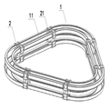
도1은 본 발명의 평면 완구 궤도의 입체 구조 모식도이다.
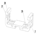
도2는 본 발명의 프레임형 부재와 스트립 레일의 연결 상태 모식도이다.
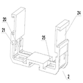
도3은 본 발명의 제2 형상의 프레임형 부재와 스트립 레일의 연결 상태 모식도이다.
도4는 본 발명의 제3 형상의 프레임형 부재와 스트립 레일의 연결 상태 모식도이다.
도5는 본 발명의 제4 형상의 프레임형 부재의 입체 상태 모식도이다.
도6은 본 발명의 제5 형상의 프레임형 부재의 입체 상태 모식도이다.
도7은 본 발명의 멀티형상의 프레임형 부재를 혼합 사용한 완구 궤도의 입체 상태 모식도이다.
도8은 본 발명의 두개의 프레임형 부재의 조립 상태의 입체 상태 모식도이다.
도9는 본 발명의 서포트 바와 프레임형 부재의 연결 상태 모식도이다.
도10은 본 발명의 입체 완구 궤도의 입체 상태 모식도이다.1 is a three-dimensional structure diagram of a planar toy track of the present invention.
2 is a schematic diagram illustrating a connection state of a frame member and a strip rail according to the present invention.
Fig. 3 is a schematic diagram showing the connection state of the frame member and the strip rail of the second shape of the present invention. Fig.
4 is a schematic diagram illustrating a connection state between a frame member and a strip rail of a third shape according to the present invention.
5 is a stereoscopic schematic diagram of a frame member of a fourth shape according to the present invention.
6 is a stereoscopic schematic diagram of a frame member of a fifth shape according to the present invention.
7 is a stereoscopic schematic diagram of a toy track using a multi-shaped frame member according to the present invention.
8 is a stereoscopic schematic diagram of an assembled state of two frame members according to the present invention.
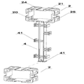
Fig. 9 is a schematic diagram showing the connection state between the support bar and the frame member of the present invention.
10 is a stereoscopic state schematic diagram of the cubic toy orbit according to the present invention.
도1 내지 도2에 도시된 바와 같이, 당해 발명에 따른 자유롭게 조립 가능한 완구 궤도는 복수개의 가이드 레일과 연결부재를 포함하는 바, 그 중 매 하나의 가이드 레일은 모두 좌우 두개의 독립된 스트립 레일(1)이고, 연결부재는 프레임형 부재(2)이며, 상기 프레임형 부재(2)는 내부프레임 변에서의 상대적 위치에 스트립 레일(1)의 단부가 연결되도록 하는 연결부재를 구비하고, 좌우 두개의 가이드 레일(1)의 양단은 각각 두개의 프레임형 부재(2)의 연결부재에 연결되어 궤도면 중부가 비게되는 궤도체를 형성함으로써, 완구차의 좌우 바퀴가 좌우 두개의 스트립 레일(1)에 바로 놓이도록 하여 완구차가 궤도를 따라 주행하도록 하는 것을 실현하고, 완구차의 폭크기에 근거하여 대응되는 폭의 프레임형 부재(2)를 선택하여 스트립 레일(1)과 연결한다. 이로써 궤도의 폭을 넓히고 완구 궤도의 적용 범위를 효과적으로 향상시킨다. 또한, 조립의 난도 및 기법은 기존의 가이드 레일에 전후로 맞추는 것에 비하여 난도 및 기법이 높으므로, 플레이어의 조작능력과 지력을 더욱 훈련시킬 수 있다. 1 and 2, the freely assemblable toy track according to the present invention includes a plurality of guide rails and a connecting member, wherein each one of the guide rails has two independent left and right strip rails 1 ), The connecting member is a frame member (2), and the frame member (2) has a connecting member for connecting an end portion of the strip rail (1) to a relative position on the side of the inner frame, Both ends of the
도2에 도시된 바와 같이, 상기 실시예의 스트립 레일(1)은 대체적으로 단면이 "L"형을 나타내는 바, 그 중 가로변은 완구차의 바퀴가 접촉되도록 하는 것이고, 세로변은 리브로서 궤도에서 주행하는 완구차가 궤도를 이탈하는 것을 방지한다. 당해 실시예의 프레임형 부재(2)는 몇가지 설계방안을 사용할 수 있다. 도2에 도시된 바와 같이, 상기 도면 중의 프레임형 부재(2)는 사각형 프레임체이고, 상기 프레임형 부재(2) 상의 연결부재는 내부프레임 코너 위치의 서로 인접한 두개의 내부프레임 변에 개설되는 오목홈(21)이며, 두개의 오목홈(21)에서 그의 코너 위치까지의 거리는 꼭 알맞게 "L"형 스트립 레일(1)의 두개의 변의 길이와 일치하고, 스트립 레일(1)의 양단부에는 외측으로 돌출되는, 두개의 오목홈(21) 중에 삽입 연결되는 두개의 돌출 스트립(11)이 대응되게 구비되며, 상기 프레임형 부재(2)의 네개 내부프레임 코너 위치에 모두 연결부재가 구비되어 있으므로, 네개의 스트립 레일(1)을 장착할 수 있어 상하 궤도를 형성하여 양면 완구차의 주행에 적합하다. 도3에 도시된 바와 같이, 상기 도면 중의 프레임형 부재(2)는 사각형 프레임체이고, 상기 프레임형 부재(2)의 연결부재는 내부프레임 코너 위치의 서로 인접한 두개의 내부프레임 변으로부터 돌출되는 파렛트(22)이고, 상기 두개의 파렛트(22)와 두개의 파렛트(22)가 소재하는 내부프레임 코너는 스트립 레일(1)이 삽입되도록 하는 코너부재를 공동으로 형성하며, 스트립 레일(1)이 두개의 파렛트(22) 사이의 위치에 삽입될 때, 스트립 레일(1)의 두개의 가장자리면은 바로 파렛트(22)와 면접촉되어 고정되고, 상기 프레임형 부재(2)의 네개의 내부프레임 코너 위치에 모두 연결부재가 구비되어 네개의 스트립 레일(1)을 장착할 수 있다. 도4에 도시된 바와 같이, 상기 도면 중의 프레임형 부재(2)는 사각형 프레임체이고, 상기 프레임형 부재(2)의 연결부재는 외부프레임 코너 위치의 서로 인접한 두개의 외부프레임 변에 돌출 설치되는 리브(23)이며, 스트립 레일(1)의 단부에는 크기가 리브(23) 및 외부프레임 코너에 의해 형성되는 코너부재 크기와 동일한 코너 삽입판(13)이 대응되게 외측으로 돌출 구비되며, 상기 코너 삽입판(13)과 코너부재가 서로 삽입 연결된 후 프레임형 부재(2)의 내부프레임 변과 스트립 레일(1)의 궤도면이 일치된다. 따라서, 완구차가 궤도에서의 주행에 영향을 미치지 않는다. 상기 프레임형 부재(2)의 네개 외부프레임 코너 위치에 모두 연결부재가 구비되어 네개의 스트립 레일(1)을 장착할 수 있다. 도5에 도시된 바와 같이, 도면 중의 프레임형 부재(2)는 "![]()
![]()
![]()
![]()
![]()
![]()
![]()
![]()
![]()
![]()
도2 내지 도5에 도시된 바와 같이, 이러한 프레임형 부재(2)의 외부프레임 변에 맞춤부가 구비되고, 상기 맞춤부는 "工"형 절반으로 이루어지는 삽입연결부(24)이다. 도6에 도시되는 "![]()
![]()
이중 궤도 또는 다중 궤도의 궤도체로 조립하고자 할 때, 상기 프레임형 부재(2)는 맞춤부의 상호적 일치를 통하여 "工"형 삽입연결 위치를 형성하고, 하나의 "工"형 삽입연결부재(3)를 이용하여 상기 "工"형 삽입연결위치에 삽입시킴으로써 두개의 프레임형 부재(2)를 함께 나란히 배치한다. 도8에 도시된 바와 같이, 두개의 프레임형 부재(2)를 맞추어 스트립 레일(1)에 조립하면 이중 궤도체 또는 다중 궤도체를 형성할 수 있다. 도7에 도시된 것이 바로 이중 완구 궤도로서, 두명의 플레이어가 완구차 경기 게임을 할 수 있도록 한다. Type interposing
도9 및 도10에 도시된 바와 같이, 상기 발명은 서포트 바(4)를 더 포함하고, 프레임형 부재(2)는 외부프레임 변에 서포트 바(4)가 연결되도록 하는 연결부재를 구비하고, 상기 연결부재 역시 "工"형을 절반으로 이루어지는 삽입연결부(24)이다. 즉, 프레임형 부재(2)의 맞춤부는 서포트 바(4)가 연결되도록 하는 연결부재로도 사용될 수 있다. 동시에 서포트 바(4)의 양단과 로드체에 모두 "工"형 절반인 삽입연결부(24)와 삽입 연결 및 배합되는 "II"형 삽입연결핀(41)이 구비된다. 매 하나의 "II"형 삽입연결핀(41)은 하나의 프레임형 부재(2)의 "工"형 절반인 삽입연결부(24)와 연결될 수 있다. 따라서, 서포트 바(4)와 배합하여 여러가지 입체 형태의 완구 궤도를 조립할 수 있다. 도10에 도시된 입체 완구 궤도를 제외하고도, 나선형 입체 완구 궤도, 대관람차 입체 완구 궤도 등등으로 조립될 수 있어, 플레이어의 상상력과 조작능력을 충분히 자극할 수 있다. 따라서, 흥미성이 강할 뿐만 아니라 또한 지력의 발전에도 유리하다. 이 밖에, 다른 부품들을 더 배합하여 더욱 많은 형상의 흥미있는 완구 궤도를 조립할 수 있다.9 and 10, the invention further includes a
본 발명은 구체적인 실시예를 참조하여 설명하였지만, 이러한 설명은 본 발명에 대하여 한정적인 의미를 가지는 것이 아니다. 본 발명의 설명을 참조하여 개시되는 실시예의 다른 변화는 본 발명이 속하는 기술분야에서 통상의 지식을 가진 자들에 의해 예상될 수 있는 것으로, 이러한 변화는 특허청구범위에서 한정하는 범위 내에 속해야 할 것이다. While the present invention has been described with reference to specific embodiments, such description is not meant to limit the present invention. Other variations of the embodiments disclosed with reference to the description of the invention may be expected by one of ordinary skill in the art to which the invention pertains and such variations are intended to be within the scope of the claims.
Claims (10)
상기 매 하나의 가이드 레일은 모두 좌우 두개의 독립된 스트립 레일(1)이고, 상기 연결부재는 프레임형 부재(2)이며, 상기 프레임형 부재(2)는 내부프레임 변에서의 상대적 위치에 스트립 레일(1)의 단부가 연결되도록 하는 연결부재를 구비하고, 전후 두 구간의 가이드 레일 사이는 프레임형 부재(2)를 통하여 연결되어 궤도면 중부가 비게되는 궤도체를 형성하는 것을 특징으로 하는 자유롭게 조립 가능한 완구 궤도.In a freely assemblable toy track including a plurality of guide rails and connecting members,
Wherein each of the one guide rail is a left and right two independent strip rails 1 and the connecting member is a frame member 2 and the frame member 2 has a strip rail at a relative position on the side of the inner frame 1) are connected to each other through a frame member (2), and between the two front and rear guide rails is connected via a frame member (2) to form an orbital member in which the center of the orbital plane is hollow. Toys orbit.
상기 스트립 레일(1)은 단면이 "L"형을 나타내는 스트립 레일이고, 상기 프레임형 부재(2)는 사각형 프레임체 또는 "
The strip rail 1 is a strip rail whose cross-section is of an "L" shape, and the frame member 2 is a rectangular frame or "
상기 프레임형 부재(2)의 연결부재는 내부프레임 코너 위치의 서로 인접한 두개의 내부프레임 변에 개설되는 오목홈(21)이고, 상기 스트립 레일(1)의 양단부에는 외측으로 돌출되는, 오목홈(21) 중에 삽입 연결되는 돌출 스트립(11)이 대응되게 구비되는 것을 특징으로 하는 자유롭게 조립 가능한 완구 궤도.3. The method of claim 2,
The connecting member of the frame member 2 is a concave groove 21 formed at two inner frame sides adjacent to each other at an inner frame corner position and a concave groove 21 protruding outward at both ends of the strip rail 1 21. The toy track according to claim 1, wherein the protruding strips (11) are inserted into the protruding strips (21).
상기 프레임형 부재(2)의 연결부재는 내부프레임 코너 위치의 서로 인접한 두개의 내부프레임 변으로부터 돌출되는 파렛트(22)이고, 상기 두개의 파렛트(22)와 두개의 파렛트(22)가 소재하는 내부프레임 코너는 상기 스트립 레일(1)이 삽입되도록 하는 코너부재를 공동으로 형성하는 것을 특징으로 하는 자유롭게 조립 가능한 완구 궤도. 3. The method of claim 2,
The connecting member of the frame member 2 is a pallet 22 protruding from two inner frame sides adjacent to each other at an inner frame corner position and the inside of the frame member 2 Wherein the frame corner is formed with a corner member for allowing the strip rail (1) to be inserted therein.
상기 프레임형 부재(2)의 연결부재는 외부프레임 코너 위치의 서로 인접한 두개의 외부프레임 변에 돌출 설치되는 리브(23)이고, 상기 스트립 레일(1)의 단부에는 크기가 상기 리브(23) 및 외부프레임 코너에 의해 형성되는 코너부재 크기와 동일한 코너 삽입판(13)이 대응되게 외측으로 돌출 구비되며, 상기 코너 삽입판(13)과 상기 코너부재가 서로 삽입 연결된 후 상기 프레임형 부재(2)의 내부프레임 변과 상기 스트립 레일(1)의 궤도면이 일치되는 것을 특징으로 하는 자유롭게 조립 가능한 완구 궤도.3. The method of claim 2,
The connecting member of the frame member 2 is a rib 23 protruding from two outer frame sides adjacent to each other at an outer frame corner position and the rib 23 is formed at the end of the strip rail 1, A corner insertion plate 13 having the same size as a corner member formed by an outer frame corner is correspondingly protruded outwardly and the corner insertion plate 13 and the corner member are inserted into each other, And the orbital surface of the strip rail (1) coincides with the orbit surface of the strip rail (1).
상기 프레임형 부재(2)의 외부프레임 변에 맞춤부가 구비되고, 상기 맞춤부는 "工"형 절반으로 이루어지는 삽입연결부(24)인 것을 특징으로 하는 자유롭게 조립 가능한 완구 궤도.The method according to claim 1,
Characterized in that the fitting portion is provided on the outer frame side of the frame member (2), and the fitting portion is an insertion connecting portion (24) composed of an "art" half.
상기 두개의 프레임형 부재(2)는 맞춤부를 통하여 서로 일치되어 "工"형 삽입연결부를 형성하고, 하나의 "工"형 삽입연결부재(3)를 이용하여 상기 "工"형 삽입연결부에 삽입시킴으로써 두개의 프레임형 부재(2)를 맞추어 이중 궤도체 또는 다중 궤도체를 형성하도록 실현하는 것을 특징으로 하는 자유롭게 조립 가능한 완구 궤도.The method according to claim 6,
The two frame members 2 are joined to each other through the fitting portion to form an "articulated insertion connection" and inserted into the "articulated insertion connection portion" using one "articulated insertion connection member 3" And the two frame members (2) are aligned to form a dual orbital or multi-orbital body.
서포트 바(4)를 더 포함하고, 상기 프레임형 부재(2)는, 외부프레임 변에 상기 서포트 바(4)가 연결되도록 하는 연결부재를 구비하고, 서포트 바(4), 프레임형 부재(2) 및 가이드 레일 등 3자의 배합을 통하여 입체 궤도체를 조합하는 것을 특징으로 하는 자유롭게 조립 가능한 완구 궤도.The method according to claim 1,
The frame member (2) further comprises a support member (4), and the support bar (4) is connected to the outer frame side. The support bar (4), the frame member ) And a guide rail, wherein the stereoscopic orbit bodies are combined with each other.
상기 프레임형 부재(2)의 연결부재는 "工"형 절반으로 이루어지는 삽입연결부(24)이고, 상기 서포트 바(4)의 양단 및 로드체 중의 적어도 하나에 상기 "工"형 절반으로 이루어지는 삽입연결부(24)와 삽입 연결 및 배합되는 "II"형 삽입연결핀(41)이 구비되는 것을 특징으로 하는 자유롭게 조립 가능한 완구 궤도.9. The method of claim 8,
The connection member of the frame member 2 is an insertion connection portion 24 made of an "engineering" half, and at least one of both ends of the support bar 4 and the rod member has an insertion connection portion Shaped insert pin (41) is inserted and connected to the insert pin (24).
상기 스트립 레일(1)의 양단부에 탄성 스냅(15)이 구비되고, 상기 프레임형 부재(2)의 연결부재 위치에 탄성 스냅(15)이 걸리도록 하는 걸림홀(25)이 대응되게 구비되는 것을 특징으로 하는 자유롭게 조립 가능한 완구 궤도.The method according to claim 1,
It is preferable that an elastic snap 15 is provided at both ends of the strip rail 1 and a locking hole 25 is provided correspondingly to an elastic snap 15 at a connection member position of the frame member 2 Featuring freely assemblable toy tracks.
Applications Claiming Priority (3)
| Application Number | Priority Date | Filing Date | Title |
|---|---|---|---|
| CN201410202455.1 | 2014-05-14 | ||
| CN201410202455.1A CN103990287A (en) | 2014-05-14 | 2014-05-14 | Toy track capable of being freely spliced |
| PCT/CN2015/078838 WO2015172716A1 (en) | 2014-05-14 | 2015-05-13 | Freely assemblable toy track |
Publications (2)
| Publication Number | Publication Date |
|---|---|
| KR20170016319A true KR20170016319A (en) | 2017-02-13 |
| KR101902090B1 KR101902090B1 (en) | 2018-09-27 |
Family
ID=51304773
Family Applications (1)
| Application Number | Title | Priority Date | Filing Date |
|---|---|---|---|
| KR1020167028268A KR101902090B1 (en) | 2014-05-14 | 2015-05-13 | Freely assemblable toy track |
Country Status (11)
| Country | Link |
|---|---|
| US (1) | US10092848B2 (en) |
| EP (1) | EP3144042B1 (en) |
| JP (1) | JP6346960B2 (en) |
| KR (1) | KR101902090B1 (en) |
| CN (1) | CN103990287A (en) |
| AU (1) | AU2015258581B2 (en) |
| BR (1) | BR112016025059A2 (en) |
| CA (1) | CA2945222A1 (en) |
| MX (1) | MX2016013730A (en) |
| RU (1) | RU2667824C2 (en) |
| WO (1) | WO2015172716A1 (en) |
Families Citing this family (8)
| Publication number | Priority date | Publication date | Assignee | Title |
|---|---|---|---|---|
| JP4859206B2 (en) | 2006-02-20 | 2012-01-25 | 株式会社セガ トイズ | toy |
| US10258896B2 (en) | 2013-09-10 | 2019-04-16 | Box Tiles Llc | Magnetic building tiles |
| MX2016007249A (en) | 2013-12-05 | 2017-01-05 | 3M Innovative Properties Co | Container for a spraying device. |
| CN103990287A (en) * | 2014-05-14 | 2014-08-20 | 广东奥飞动漫文化股份有限公司 | Toy track capable of being freely spliced |
| CN204428819U (en) | 2015-03-18 | 2015-07-01 | 浙江忠协工艺品有限公司 | Rail toy syndeton |
| USD868170S1 (en) * | 2017-06-29 | 2019-11-26 | Box Tiles Llc | Toy bridge clip |
| USD928888S1 (en) * | 2018-01-17 | 2021-08-24 | Ravensburger Ag | Toy constructor piece |
| US11712636B1 (en) | 2022-08-12 | 2023-08-01 | Spin Master Ltd. | Transformable toy |
Family Cites Families (26)
| Publication number | Priority date | Publication date | Assignee | Title |
|---|---|---|---|---|
| CH388156A (en) * | 1960-09-29 | 1965-02-15 | Rudolf Dipl Ing Waser | Trackless running track for toy vehicles |
| US3225487A (en) * | 1963-10-17 | 1965-12-28 | Gilbert Co A C | Model roadbed including adjustable trestles and supports |
| DE1811940A1 (en) * | 1968-11-30 | 1970-06-11 | Artur Fischer | Toy track system that can be assembled from track sections |
| US3712539A (en) * | 1970-09-18 | 1973-01-23 | Mattel Inc | Track system for toy vehicle |
| JPS4817429Y1 (en) * | 1971-07-19 | 1973-05-18 | ||
| US4080742A (en) * | 1974-11-04 | 1978-03-28 | Osterried James L | Kit of parts for forming a curved member, and curved member formed thereby |
| JPS52146398U (en) * | 1976-04-28 | 1977-11-07 | ||
| JPS52146398A (en) | 1976-05-28 | 1977-12-06 | Goal Kk | Tumbler lock |
| DE3005120A1 (en) | 1980-02-12 | 1981-08-20 | Artur Dr.H.C. 7244 Waldachtal Fischer | DRIVING AND / OR GUIDE RAIL FOR TOY DRIVING MODELS |
| JPH01107798U (en) | 1988-01-12 | 1989-07-20 | ||
| JPH0745277Y2 (en) * | 1989-09-14 | 1995-10-18 | 株式会社トープレ | Block toys |
| US5681201A (en) * | 1995-03-20 | 1997-10-28 | Silverlit Technology Ltd. | Toy building system |
| US5924907A (en) | 1995-12-19 | 1999-07-20 | Tobin; Adam Zev | Marble track construction toy |
| JPH10235027A (en) * | 1997-02-24 | 1998-09-08 | Masami Suzuki | Toy of automobile, etc., and course of travel |
| JP2002166065A (en) | 2000-12-05 | 2002-06-11 | Tomy Co Ltd | Track for running and connection mechanism |
| US6676480B2 (en) * | 2002-05-31 | 2004-01-13 | Mattel, Inc. | Staging mechanism for toy vehicle playset |
| US20030224697A1 (en) * | 2002-05-31 | 2003-12-04 | Sheltman David A. | Inverting toy vehicle playset |
| US20050287919A1 (en) * | 2004-01-23 | 2005-12-29 | Sheltman David A | Toy vehicle track structure |
| JP2006314533A (en) * | 2005-05-12 | 2006-11-24 | T & T:Kk | Attraction toy |
| DE102005043658B3 (en) * | 2005-09-13 | 2006-06-14 | Modelleisenbahn Gmbh | Model railway equipment rolling material illumination device, has plastic-shaped part implemented as cap, where cap ends or sections of connection line connects with upper side of spring contact holder, if cap is attached on base part |
| US20070209543A1 (en) | 2006-01-04 | 2007-09-13 | Ans Beaulieu | Toy roller coaster assembly |
| TWI434722B (en) * | 2010-07-30 | 2014-04-21 | Yung Sen Ltd Company | Track-type game system |
| CN202460122U (en) * | 2012-02-23 | 2012-10-03 | 杭州网豆数字技术有限公司 | Jet coaster toy capable of spirally ascending |
| CN203577321U (en) * | 2013-11-15 | 2014-05-07 | 施议铭 | Intelligence-beneficial Ferris wheel track toy |
| CN203886187U (en) * | 2014-05-14 | 2014-10-22 | 广东奥飞动漫文化股份有限公司 | Toy rail capable of being freely assembled |
| CN103990287A (en) | 2014-05-14 | 2014-08-20 | 广东奥飞动漫文化股份有限公司 | Toy track capable of being freely spliced |
-
2014
- 2014-05-14 CN CN201410202455.1A patent/CN103990287A/en active Pending
-
2015
- 2015-05-13 RU RU2016142269A patent/RU2667824C2/en not_active IP Right Cessation
- 2015-05-13 AU AU2015258581A patent/AU2015258581B2/en not_active Ceased
- 2015-05-13 CA CA2945222A patent/CA2945222A1/en not_active Abandoned
- 2015-05-13 MX MX2016013730A patent/MX2016013730A/en unknown
- 2015-05-13 WO PCT/CN2015/078838 patent/WO2015172716A1/en active Application Filing
- 2015-05-13 EP EP15792348.3A patent/EP3144042B1/en not_active Not-in-force
- 2015-05-13 KR KR1020167028268A patent/KR101902090B1/en active IP Right Grant
- 2015-05-13 BR BR112016025059A patent/BR112016025059A2/en not_active IP Right Cessation
- 2015-05-13 US US15/301,883 patent/US10092848B2/en not_active Expired - Fee Related
- 2015-05-13 JP JP2016561368A patent/JP6346960B2/en not_active Expired - Fee Related
Also Published As
| Publication number | Publication date |
|---|---|
| KR101902090B1 (en) | 2018-09-27 |
| AU2015258581B2 (en) | 2017-08-10 |
| RU2667824C2 (en) | 2018-09-24 |
| EP3144042B1 (en) | 2019-02-20 |
| US20170028305A1 (en) | 2017-02-02 |
| JP6346960B2 (en) | 2018-06-20 |
| WO2015172716A1 (en) | 2015-11-19 |
| MX2016013730A (en) | 2017-04-27 |
| AU2015258581A1 (en) | 2016-11-03 |
| US10092848B2 (en) | 2018-10-09 |
| JP2017513578A (en) | 2017-06-01 |
| EP3144042A4 (en) | 2017-12-27 |
| RU2016142269A3 (en) | 2018-06-14 |
| EP3144042A1 (en) | 2017-03-22 |
| RU2016142269A (en) | 2018-06-14 |
| CN103990287A (en) | 2014-08-20 |
| BR112016025059A2 (en) | 2017-08-15 |
| CA2945222A1 (en) | 2015-11-19 |
Similar Documents
| Publication | Publication Date | Title |
|---|---|---|
| KR101902090B1 (en) | Freely assemblable toy track | |
| US20100248586A1 (en) | Hobby vehicle track system | |
| TWI620591B (en) | Toy track and toy track set | |
| KR100524154B1 (en) | A panel type magnetic toy | |
| US3013726A (en) | Reversible track set for toy vehicles | |
| US20110250822A1 (en) | Toy race car and track | |
| US10391415B2 (en) | Connecting member for self-assembly toy | |
| GB2401067A (en) | Track and track connectors for a toy vehicle | |
| WO2015172717A1 (en) | Building block assembling toy track | |
| US20200391129A1 (en) | Toy Vehicle Raceways with Clipping Mechanism and Supporting Block Builder | |
| CN203886187U (en) | Toy rail capable of being freely assembled | |
| KR200485228Y1 (en) | Block assembly toy having connecting block | |
| KR101945146B1 (en) | Set of rail block toy | |
| US1242273A (en) | Structural toy. | |
| US20180169534A1 (en) | Building block set and building block robot | |
| US20220314135A1 (en) | Magnetic block toy, and travel course design drawing | |
| KR101497767B1 (en) | Driving rail for toy train | |
| CN203886186U (en) | Modularized assembled toy railway | |
| KR200458252Y1 (en) | Block | |
| KR200173818Y1 (en) | Unit track member for toy motor vehicle | |
| US20230271098A1 (en) | Assembly-type toy | |
| KR20200097980A (en) | Assembled toys | |
| KR200291808Y1 (en) | A prefabricate race track for toy car | |
| TWM594981U (en) | Rail structure | |
| KR200232834Y1 (en) | Toy car racing track |
Legal Events
| Date | Code | Title | Description |
|---|---|---|---|
| A201 | Request for examination | ||
| E902 | Notification of reason for refusal | ||
| E701 | Decision to grant or registration of patent right | ||
| GRNT | Written decision to grant |