KR20170016184A - Laundry Treating Apparatus - Google Patents
Laundry Treating Apparatus Download PDFInfo
- Publication number
- KR20170016184A KR20170016184A KR1020150109620A KR20150109620A KR20170016184A KR 20170016184 A KR20170016184 A KR 20170016184A KR 1020150109620 A KR1020150109620 A KR 1020150109620A KR 20150109620 A KR20150109620 A KR 20150109620A KR 20170016184 A KR20170016184 A KR 20170016184A
- Authority
- KR
- South Korea
- Prior art keywords
- ring
- drum
- balancing unit
- unit
- housing
- Prior art date
Links
Images


Classifications
-
- D—TEXTILES; PAPER
- D06—TREATMENT OF TEXTILES OR THE LIKE; LAUNDERING; FLEXIBLE MATERIALS NOT OTHERWISE PROVIDED FOR
- D06F—LAUNDERING, DRYING, IRONING, PRESSING OR FOLDING TEXTILE ARTICLES
- D06F37/00—Details specific to washing machines covered by groups D06F21/00 - D06F25/00
- D06F37/20—Mountings, e.g. resilient mountings, for the rotary receptacle, motor, tub or casing; Preventing or damping vibrations
- D06F37/22—Mountings, e.g. resilient mountings, for the rotary receptacle, motor, tub or casing; Preventing or damping vibrations in machines with a receptacle rotating or oscillating about a horizontal axis
-
- D—TEXTILES; PAPER
- D06—TREATMENT OF TEXTILES OR THE LIKE; LAUNDERING; FLEXIBLE MATERIALS NOT OTHERWISE PROVIDED FOR
- D06F—LAUNDERING, DRYING, IRONING, PRESSING OR FOLDING TEXTILE ARTICLES
- D06F37/00—Details specific to washing machines covered by groups D06F21/00 - D06F25/00
- D06F37/20—Mountings, e.g. resilient mountings, for the rotary receptacle, motor, tub or casing; Preventing or damping vibrations
-
- D06F37/203—
-
- Y02B40/50—
Abstract
Description
본 발명은 의류처리장치에 관한 것으로, 더 상세하게는 밸런서를 포함하는 의류처리장치에 관한 것이다.BACKGROUND OF THE
종래의 의류처리장치는 외관을 형성하는 캐비닛과, 캐비닛의 내부에 설치되는 터브(Tub)와, 상기 터브 내측에 회전 가능하게 설치되어 세탁물을 세탁하는 드럼(Drum)과, 상기 드럼을 회전시킬 수 있도록 구동부를 포함한다.The conventional clothes processing apparatus includes a cabinet forming an outer appearance, a tub installed inside the cabinet, a drum rotatably installed inside the tub to wash the laundry, And a driving unit.
드럼은 내부에 저장된 세탁물의 위치에 따라 동적균형(Dynamic equribrium balance)를 유지하기 못하고 회전할 수 있다. The drum can rotate without maintaining a dynamic balance depending on the location of the laundry stored therein.
동적균형은 회전체가 회전할 때 드럼에 발생하는 관성모멘트가 0이 되는 상태를 말한다. 관성모멘트는 드럼의 회전축을 중심으로 질량분포가 일정한 경우에 0이 된다. 따라서 의류처리장치에 있어서 드럼의 동적균형이란 드럼의 회전시 회전축을 중심으로 질량분포가 허용범위 내에 있는 경우로 세탁물이 저장된 드럼의 진동폭이 의류처리장치에서 수용 가능한 정도 이내인 것을 말한다.Dynamic balance refers to a state in which the moment of inertia generated in the drum is zero when the rotating body rotates. The moment of inertia becomes zero when the mass distribution is constant around the rotational axis of the drum. Therefore, the dynamic balance of the drum in the garment processing apparatus means that the mass distribution of the drum is within the permissible range around the rotation axis when the drum rotates, and the vibration amplitude of the drum in which the laundry is stored is within a range acceptable by the clothes processing apparatus.
반면, 의류처리장치에서 동적균형이 깨진 상태를 언밸런스 상태(Unbalance state)라 하고, 이는 드럼의 회전시 회전축을 중심으로 질량분포가 허용범위를 벗어나 세착물이 저장된 드럼의 진동폭이 의류처리장치에서 수용 가능한 정도를 벗어난 경우를 말한다. On the other hand, a state in which the dynamic balance is broken in the garment processing apparatus is referred to as an unbalance state. This means that, when the drum rotates, the mass distribution of the drum is out of the allowable range, It refers to the case where it is out of the possible range.
언밸런스 상태로 회전하는 드럼은 회전과 함께 진동하므로 드럼의 진동은 터브나 캐비닛으로 전달되어 소음을 유발하고 드럼이 파손되는 문제가 생긴다.Since the drum rotating in an unbalanced state vibrates together with the rotation, the vibration of the drum is transmitted to the cabinet or cabinet, causing noise and damaging the drum.
종래의 의류처리장치는 드럼의 언밸런스 상태를 해소하기 위하여 밸런서를 구비하고 있으나, 종래의 밸런서는 볼(ball) 밸런서 또는 액체(liquid) 밸런서로 구비되었다.Conventional clothes processing apparatuses have a balancer for eliminating the unbalanced state of the drum, but the conventional balancer is provided with a ball balancer or a liquid balancer.
그러나, 종래의 밸런서는 드럼의 진동이 일정한 범위 내에 있는 정상상태 진동(Steady state vibration)인 경우에는 유용하지만, 드럼의 진동이 정상상태에 도달하기 전인 과도상태 진동(Transient vibration)에서는 오히려 진동이 커지는 문제가 되었다.However, the conventional balancer is useful when the vibration of the drum is steady state vibration within a certain range. However, in the transient vibration before the vibration of the drum reaches the steady state, It became a problem.
또한, 종래의 밸런서의 볼이나 액체는 드럼의 회전에 의존하여 수동적으로 이동하여 언밸런스 상태를 해소하므로 밸런싱 상태에 도달하기 위하여 시간이 소요되는 문제가 있었다.In addition, the ball or liquid of the conventional balancer moves manually depending on the rotation of the drum, thereby eliminating the unbalanced state, so that it takes time to reach the balancing state.
본 발명은 드럼의 회전에 독립적으로 드럼의 언밸런스 상태를 능동적으로 해소하는 의류처리장치를 제공하는 것을 과제로 한다.An object of the present invention is to provide a clothes processing apparatus which actively resolves the unbalanced state of the drum independently of the rotation of the drum.
또한, 본 발명은 드럼에 구비된 밸런싱 유닛의 정밀한 위치 제어가 가능한 의류처리장치를 제공하는 것을 과제로 한다.Another object of the present invention is to provide a clothes processing apparatus capable of precise position control of a balancing unit provided in a drum.
본 발명은 상술한 과제를 해결하기 위하여, 캐비닛과; 상기 캐비닛 내부에 구비되어 세탁수가 저장되는 터브와; 상기 터브 내부에 회전 가능하게 구비되고, 의류가 저장되는 드럼과; 상기 드럼에 고정된 하우징과; 상기 하우징 내부에 구비되며 폐곡선을 형성하는 수용공간과; 상기 수용공간 내부를 이동 가능하게 구비되어 상기 드럼의 언밸런싱 상태를 해소하는 밸런싱유닛과; 상기 밸런싱유닛을 이동시키기 위하여 상기 밸런싱유닛에 연결된 링과; 상기 링을 이동시키기 위하여 구비되는 작동부;를 포함하며, 상기 밸런싱유닛은 상기 수용공간을 따라 360도 회전할 수 있도록 구비된 것을 특징으로 하는 의류처리장치를 제공한다.In order to solve the above-described problems, the present invention provides a cabinet comprising: a cabinet; A tub disposed inside the cabinet to store wash water; A drum rotatably installed in the tub and storing clothes; A housing fixed to the drum; A housing space provided in the housing and defining a closed curve; A balancing unit movably installed in the accommodating space to eliminate an unbalanced state of the drum; A ring coupled to the balancing unit to move the balancing unit; And an operation unit provided to move the ring, wherein the balancing unit is rotatable 360 degrees along the accommodation space.
상기 링은 폐곡선을 형성하는 원형 또는 개방곡선으로 형성된 원호의 일부로 구비되는 것을 특징으로 한다.And the ring is provided as a part of a circular arc formed by a closed curve or an arc formed by an open curve.
상기 링의 강도는 상기 링의 형상이 상기 밸런싱유닛의 무게에 의해 변형되지 않을 정도의 강도를 가지는 것을 특징으로 한다.And the strength of the ring is such that the shape of the ring is not deformed by the weight of the balancing unit.
한편, 본 발명에서 상기 링은 제1링과 상기 제1링의 하부에 동일한 직경으로 구비되는 제2링을 포함하며, 상기 제1링에는 제1밸런싱유닛이 연결되고, 상기 제2링에는 제2밸런싱유닛이 연결되는 것을 특징으로 하는 의류처리장치를 제공할 수 있다.In the meantime, in the present invention, the ring includes a first ring and a second ring having the same diameter at the lower part of the first ring, a first balancing unit is connected to the first ring, And a balancing unit is connected to the balancing unit.
한편, 본 발명에서 상기 링은 제1링과 상기 제1링과 다른 직경으로 구비되는 제2링을 포함하며, 상기 제1링에는 제1밸런싱유닛이 연결되고, 상기 제2링에는 제2밸런싱유닛이 연결되는 것을 특징으로 하는 의류처리장치를 제공할 수 있다.Meanwhile, in the present invention, the ring includes a first ring and a second ring having a different diameter from the first ring, the first ring is connected to a first balancing unit, and the second ring is connected to a second balancing Unit can be connected to the clothes processing apparatus.
상기 링은 링가이드돌기 또는 링가이드홈을 포함하며, 상기 링가이드돌기 또는 링가이드홈에 대응되는 형상으로 상기 수용공간에 구비된 수용공간 홈 또는 수용공간 돌기를 포함하는 것을 특징으로 한다.The ring includes a ring guide protrusion or a ring guide groove, and includes a receiving space groove or a receiving space protrusion provided in the receiving space in a shape corresponding to the ring guide protrusion or the ring guide groove.
상기 링은 상기 작동부에 구비된 회전기어에 맞물려 이동할 수 있도록 상기 링의 표면에 기어이빨을 구비하는 것을 특징으로 한다.And the ring is provided with gear teeth on the surface of the ring so that the ring can be engaged with the rotating gear provided in the operating portion.
상기 링은 상기 작동부에 구비된 회전기어에 맞물려 이동할 수 있도록 체인으로 구비되는 것을 특징으로 한다.And the ring is provided as a chain so as to be able to move and engage with a rotary gear provided in the operating portion.
한편, 본 발명에서 상기 밸런싱유닛은 상기 드럼의 중심축에 대하여 원주방향으로 원호를 이루도록 구비되는 것을 특징으로 하는 의류처리장치를 제공한다.According to another aspect of the present invention, there is provided a clothes processing apparatus, wherein the balancing unit is provided so as to be circular in a circumferential direction with respect to a central axis of the drum.
상기 밸런싱유닛은 상기 링의 외주면에 연결되는 것을 특징으로 할 수 있다.And the balancing unit is connected to the outer circumferential surface of the ring.
한편, 상기 밸런싱유닛은 상기 드럼의 회전속도가 소정속도 이상인 경우에 상기 수용공간에 접촉하여 고정되는 것을 특징으로 한다.The balancing unit is fixed in contact with the accommodating space when the rotational speed of the drum is equal to or higher than a predetermined speed.
한편, 본 발명은 상기 수용공간 내부에서 상기 밸런싱유닛의 이동을 원활하게 하기 위하여 상기 밸런싱유닛의 양단에 구비된 롤러;을 포함하는 것을 특징으로 하는 의류처리장치를 제공할 수 있다.According to another aspect of the present invention, there is provided a clothes processing apparatus comprising: a roller provided at both ends of the balancing unit to facilitate movement of the balancing unit within the receiving space.
한편, 본 발명은 상기 수용공간과 상기 밸런싱유닛을 이격시키기 위하여 상기 밸런싱유닛 또는 상기 수용공간의 내부 측면에 구비되는 간격유지부;를 포함하는 것을 특징으로 하는 의류처리장치를 제공할 수 있다.According to another aspect of the present invention, there is provided a garment processing apparatus including a balancing unit or a gap holding unit provided on an inner side surface of the accommodation space to separate the accommodation space from the balancing unit.
한편, 본 발명은 상기 밸런싱유닛에 구비된 자성체와; 상기 자성체의 자성을 감지할 수 있도록 상기 터브 또는 상기 캐비닛에 구비된 센싱부;를 포함하는 것을 특징으로 하는 의류처리장치를 제공할 수 있다.Meanwhile, the present invention may include a magnetic body provided in the balancing unit; And a sensing unit provided in the tub or the cabinet to sense magnetism of the magnetic body.
본 발명은 드럼의 회전에 독립적으로 드럼의 언밸런스 상태를 능동적으로 해소하는 의류처리장치를 제공하는 효과가 있다.The present invention has the effect of providing a clothes processing apparatus that actively resolves the unbalanced state of the drum independently of the rotation of the drum.
또한, 본 발명은 드럼에 구비된 밸런싱 유닛의 정밀한 위치 제어가 가능한 의류처리장치를 제공하는 효과가 있다.In addition, the present invention has an effect of providing a clothes processing apparatus capable of precise position control of a balancing unit provided in a drum.
도 1은 본 발명의 의류처리장치의 일예를 나타낸 것이다.
도 2는 본 발명의 의류처리장의 일부분의 분해사시도를 도시한 것이다.
도 3은 본 발명의 의류처리장치에 구비된 드럼의 분해사시도를 도시한 것이다.
도 4는 본 발명의 밸런서의 분해 사시도를 도시한 것이다.
도 5는 본 발명의 밸런서의 단면도의 일예이다.
도 6은 본 발명의 밸런서의 단면도의 다른 예이다.
도 7은 본 발명의 밸런싱유닛의 분해 사시도를 도시한 것이다.
도 8(a)는 본 발명의 하우징에서 작동부가 구비된 부분의 단면도를 나타낸 것이다.
도 8(b)는 본 발명의 하우징의 단면도를 나타낸 것이다.
도 9는 본 발명의 작동부의 사시도를 나타낸 것이다.
도 10은 도 9의 투시 저면도를 나타낸 것이다.
도 11는 본 발명의 밸런서의 다른 예를 나타낸 것이다.
도 12은 본 발명의 밸런서의 다른 예인 도 11의 밸런서의 단면도를 나타낸 것이다.
도 13(a)는 본 발명의 스파이더의 단면도를 나타낸 것이다.
도 13(b)는 본 발명의 스파이더의 저면도를 나타낸 것이다.
도 14는 본 발명의 스파이더의 단면도를 확대하여 나타낸 것이다.
도 15(a)는 본 발명의 드럼의 후면을 나타낸 것이다.
도 15(b)는 본 발명의 드럼의 전면을 나타낸 것이다.
도 15(c)는 본 발명의 작동부연결선의 사시도를 나타낸 것이다.
도 16는 본 발명의 와이어가이더의 분해사시도 이다.
도 17(a)는 본 발명의 와이어가이더의 다른예의 단면도를 나타낸 것이다.
도 17(b)는 본 발명의 와이어가이더의 다른예의 설치예를 나타낸 것이다.Fig. 1 shows an example of a clothes processing apparatus of the present invention.
Fig. 2 shows an exploded perspective view of a part of the garment treatment plant of the present invention.
3 is an exploded perspective view of the drum of the clothes processing apparatus of the present invention.
4 is an exploded perspective view of the balancer of the present invention.
5 is an example of a sectional view of the balancer of the present invention.
Figure 6 is another example of a cross-sectional view of a balancer of the present invention.
7 shows an exploded perspective view of the balancing unit of the present invention.
8 (a) is a cross-sectional view of a portion of the housing of the present invention having an operating portion.
8 (b) is a sectional view of the housing of the present invention.
Fig. 9 is a perspective view of an operating portion of the present invention.
Fig. 10 is a perspective bottom view of Fig. 9. Fig.
11 shows another example of the balancer of the present invention.
Fig. 12 shows a cross-sectional view of the balancer of Fig. 11 which is another example of the balancer of the present invention.
13 (a) is a sectional view of the spider of the present invention.
13 (b) is a bottom view of the spider of the present invention.
14 is an enlarged view of a cross-sectional view of the spider of the present invention.
15 (a) shows a rear view of the drum of the present invention.
15 (b) shows a front view of the drum of the present invention.
Fig. 15 (c) is a perspective view of an operating part connecting line of the present invention.
16 is an exploded perspective view of the wire guider of the present invention.
17 (a) shows a cross-sectional view of another example of the wire guider of the present invention.
Fig. 17 (b) shows an example of installation of another example of the wire guider of the present invention.
이하에서는 첨부된 도면을 참고하여 본 발명의 바람직한 실시예를 상세하게 설명한다. Hereinafter, preferred embodiments of the present invention will be described in detail with reference to the accompanying drawings.
본 명세서의 모든 용어는 특별한 정의가 없는 한 본 발명이 속하는 기술분야의 통상의 기술자가 이해하는 당해 용어의 일반적 의미와 동일하고, 만약 본 명세서에 사용된 용어가 당해 용어의 일반적 의미와 충돌하는 경우에는 본 명세서에 사용된 정의에 따른다. 또한, 본 명세서의 방향은 사용자가 의류처리장치를 도어측으로 바라보았을 때 의류처리장치의 도어 측을 전방, 의류처리장치의 모터 측을 후방으로 정의하며, 사용자의 좌측과 우측을 각각 의류처리장치의 좌측과 우측으로 정의한다.Unless defined otherwise, all terms used herein have the same meaning as commonly understood by one of ordinary skill in the art to which this invention pertains and, if the terms used herein conflict with the general meaning of the term Are as defined herein. Further, the direction of the present specification is such that the door side of the clothes processing apparatus is defined as the front side and the motor side of the garment processing apparatus is defined as the rear side when the user views the garment processing apparatus toward the door side, Left and right.
한편, 이하에 기술될 장치의 구성이나 제어방법은 본 발명의 실시예를 설명하기 위한 것일 뿐 본 발명의 권리범위를 한정하기 위함은 아니며, 명세서 전반에 걸쳐서 동일하게 사용된 참조번호들은 동일한 구성요소들을 나타낸다.It is to be understood that the present invention is not limited to the details of the embodiments described below, .
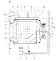
도 1은 본 발명의 의류처리장치의 일예를 나타낸 것이다. 도 1을 참조하여 본 발명의 의류처리장치에 대하여 설명한다.Fig. 1 shows an example of a clothes processing apparatus of the present invention. The garment disposal apparatus of the present invention will be described with reference to Fig.
본 발명의 의류처리장치는 캐비닛(1)과, 상기 캐비닛(1) 내부에 구비되어 세탁수가 저장되는 터브(2)와, 상기 터브(2) 내부에 회전 가능하게 구비되고, 의류가 저장되는 드럼(4)을 포함한다.The clothes processing apparatus of the present invention comprises a
상기 캐비닛(1)은 외관을 형성하며, 의류를 출입시킬 수 있는 제1투입구(122)를 일측에 구비하며, 제1투입구(122)를 개폐하는 도어(12)를 구비한다.The
상기 캐비닛(1)의 내부에는 세착수가 저장되는 터브(2)가 구비될 수 있다. 또한, 터브(2)의 내부에는 회전 가능하고 의류가 저장되는 드럼(4)이 구비될 수 있다.The
터브(2)는 터브(2)를 캐비닛 내부에서 터브지지부에 의해 지지되며, 터브지지부는 터브의 상부에 구비된 스프링(24)과 터브의 하부에 구비된 댐퍼(26)에 의해 캐비닛(1)에 연결 및 지지되어 터브(2)의 진동이 캐비닛으로 전달되는 것을 방지한다.The
터브(2)와 드럼(4)은 원통형으로 구비되며, 전방에 각각 제2투입구(22)와 제3투입구(442)를 구비한다. 따라서, 사용자는 의류를 제1투입구(122), 제2투입구(22), 제3투입구(442)를 통해서 드럼(4) 내부로 출입시킬 수 있다.The
상기 제1투입구(122)와 제2투입구(22) 사이에는 터브(2) 내부의 세탁수가 외부로 누수되는 것을 방지하고 터브(2)의 진동이 캐비닛(1)으로 전달되는 것을 방지하는 가스켓(124)을 포함할 수 있다. 가스켓(124)은 탄성 재질로 구비되는 것을 바람직하다.A gasket (not shown) is provided between the
한편, 캐비닛(1)에는 터브(2)로 세탁수를 공급하는 급수관(31)을 포함하며, 캐비닛(1)에는 터브(2) 세제를 공급하기 위한 세제박스(32)를 포함하고, 세제박스(32)는 캐비닛(1)의 전방면에서 인출 가능한 드로워 형태로 구비될 수 있다. 급수관(31)은 터브(2)로 바로 연결될 수 있다. 또는, 급수관(31)은 세제박스(32)에 연결될 수 있으며, 이 경우, 세제박스(32)에 저장된 세제는 급수관(31)에서 공급된 세탁수와 섞여 세제박스(32)와 터브(2) 사이를 연결한 세제공급관(33)을 통해서 터브(2)에 공급된다.The
한편, 터브(2)에 저장된 세탁수를 배수하기 위하여 배수관(36) 및 배수펌프(37)을 포함한다.On the other hand, a drain pipe (36) and a drain pump (37) are provided for draining wash water stored in the tub (2).
한편, 본 발명은 드럼(4)을 회전시키기 위하여 구동부(5)를 포함한다.On the other hand, the present invention includes a
상기 구동부(5)는 터브(2)에 구비되어 자기장을 발생시키는 스테이터(52)와, 상기 스테이터(52)에서 발생한 자기장에 의해 회전력을 발생시키는 로터(54)와, 상기 로터(54)에 연결되어 터브(2)의 후면을 관통하는 회전축(56)과, 상기 회전축(56)에 연결되고 드럼(4)의 후면에 고정되는 스파이더(58)를 포함한다.The driving
도 2는 본 발명의 의류처리장의 일부분의 분해사시도를 도시한 것이다. 도 3은 본 발명의 의류처리장치에 구비된 드럼의 분해사시도를 도시한 것이다.Fig. 2 shows an exploded perspective view of a part of the garment treatment plant of the present invention. 3 is an exploded perspective view of the drum of the clothes processing apparatus of the present invention.
도 2 및 도 3을 참조하여, 본 발명의 밸런서에 대하여 설명한다. 본 발명은 드럼(4)에 구비되어 드럼(4)의 언밸런스 상태를 해소하는 밸런서(6)를 포함한다. The balancer of the present invention will be described with reference to Figs. 2 and 3. Fig. The present invention includes a balancer (6) provided in the drum (4) to eliminate unbalance of the drum (4).
상기 밸런서(6)는 드럼(4)의 전방면과 후방면 중 어느 하나에만 구비될 수 있으며, 또는 드럼(4)의 전방면과 후방면에 모두 구비될 수 있다. 전방밸런서(6a) 및 후방밸런서(6b)는 위치만 다를 뿐 내부구조는 동일하므로 이하에서 설명할 밸런서의 구조는 전방밸런서 및 후방밸런서에 각각 적용될 수 있다.The
드럼(4)은 전면과 후면이 개구된 원통 형상을 가지는 드럼통(42), 드럼통(42)의 전면 개구부에 구비되는 드럼전면(44), 드럼통의 후면 개구부에 구비되는 드럼후면(46)을 포함한다.The
상기 드럼통(42)은 내주면에 드럼(4)이 회전시 의류를 들어올릴 수 있는 리프터(424)와, 드럼통(42)을 관통하여 터브(2)에 저장된 세탁수가 드럼(4)의 내부로 유입/배출 될 수 있도록 다수의 드럼관통홀(422)을 포함한다.The
상기 드럼전면(44)은 상술한 제3투입구(442)가 구비되며, 둘레로 오목하게 함몰되어 구비되어 전방밸런서(6a)가 안착되는 전방밸런서 안착부(444)를 포함한다. 또한 상기 드럼후면(46)은 둘레로 오목하게 함몰되어 구비되어 후방밸런서(6b)가 안착되는 후방밸런서 안착부(464)를 포함하고, 스파이더(58)가 안착될 수 있도록 스파이더(58)의 형상으로 오목하게 함몰된 스파이더 안착부(462)를 포함한다.The
한편, 드럼통(42)의 전면 개구부를 통해서 드럼통(42)의 내주면으로 드럼전면(44)을 삽입하여 고정하기 위하여 드럼통(42)과 드럼전면(44)을 관통하는 제1드럼체결홀(480)이 드럼통(42)과 드럼전면(44)에 각각 구비한다. 또한, 드럼통(42)의 후면 개구부를 통해서 드럼통(42)의 내주면으로 드럼후면(46)을 삽입하여 고정하기 위하여 드럼통(42)과 드럼후면(46)을 관통하는 제1드럼체결홀(480)이 드럼통(42)과 드럼후면(46)에 각각 구비한다.A first
한편, 상기 제1드럼체결홀(480)은 후술할 밸런서(6)의 하우징(62)에 구비된 하우징체결돌기(628)에 구비된 하우징체결홀(6282)에 고정부재 등으로 고정된다. 따라서, 드럼통, 드럼전면 및 전방밸런서를 고정하고, 드럼통, 드럼후면 및 후방밸런서를 고정할 수 있도록 한다.The first
한편, 스파이더(58)를 드럼에 고정하기 위하여 드럼후면(46)의 드럼통(42)의 후면 개구부에 삽입한 상태에서 드럼후면(46)과 드럼통(42)을 관통하는 제2드럼체결홀(482)을 드럼통(42)과 드럼후면(46)에 각각 구비한다. 특히, 제2드럼체결홀(482)은 스파이더 안착부(462)에 구비된다.On the other hand, in order to fix the
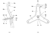
상기 스파이더(58)는 회전축(56)이 연결되는 스파이더코어(582)와, 상기 스파이더코어(582)에서 드럼의 반경방향으로 분지되고, 드럼의 후면에 고정되는 스파이더다리(584)를 포함하며, 일반적으로 스파이더다리(584)를 3개로 구비한다.(도 13 참조) 구체적으로 상기 스파이더다리(584)는 스파이더코어(582)에 연결되어 드럼의 반경방향으로 분지된 제1스파이더다리(584a)와, 제1스파이더다리(584a)에 연결되어 전방으로 절곡된 제2스파이더다리(584b)와, 제2스파이더다리(584b)에 연결되어 상측으로 절곡된 제3스파이더다리(584c)를 포함한다. The
상기 제3스파이더다리(584c)에는 전방으로 오목하게 함몰된 스파이더체결홈(586)을 구비한다. 상기 스파이더체결홈(586)에는 밸런서의 하우징(62)에 구비된 상기 하우징체결돌기(628)가 삽입된다.The
도 4는 본 발명의 밸런서의 분해 사시도를 도시한 것이다. 도 5는 본 발명의 밸런서의 단면도의 일예이다. 도 6은 본 발명의 밸런서의 단면도의 다른 예이다. 4 is an exploded perspective view of the balancer of the present invention. 5 is an example of a sectional view of the balancer of the present invention. Figure 6 is another example of a cross-sectional view of a balancer of the present invention.
도 4에 도시된 바와 같이, 상기 밸런서는 드럼(4)에 고정된 하우징(62)과 , 상기 하우징(62)의 내부에 구비되며 폐곡선을 형성하는 수용공간(622)과, 상기 수용공간(622) 내부를 이동 가능하게 구비되어 상기 드럼(4)의 언밸런싱 상태를 해소하는 밸런싱유닛(64)과, 상기 밸런싱유닛(64)을 이동시키기 위하여 상기 밸런싱유닛(64)에 연결된 링(66)과, 상기 링(66)을 이동시키기 위하여 구비되는 작동부(68)를 포함한다.4, the balancer includes a
상기 하우징(62)은 드럼(4)에 고정되고 일측이 개구된 하우징바디(62a)와, 하우징바디(62a)의 개구된 일측을 덮는 커버인 하우징커버(62b)로 구비된다.The
상기 수용공간(622)은 하우징(62) 내부에 원형궤도로 형성되며, 밸런싱유닛(64)이 이동하는 공간으로 원형의 폐곡선을 이룬다. 수용공간(622)의 형상은 반지름이 일정한 원형으로 구비되는 것이 바람직하나, 반지름이 달라지는 타원 궤도로 이뤄지는 것도 가능하다.The
상기 수용공간(622)을 이루는 하우징(62)은 제1원면(622a)과, 제1원면(622a) 보다 작은 직경을 가지는 제2원면(622b)과, 드럼(4)에 접하고 제1원면(622a)과 제2원면(622b) 사이를 연결하는 제2측면(622d)과, 제2측면(622d)의 맞은편으로 제1원면(622a)과 제2원면(622b) 사이를 연결하는 제1측면으로 이뤄진다. 다시 말해, 수용공간(622)은 제1원면(622a), 제2원면, 제1측면, 제2측면이 연결되어 내부에 이루는 공간을 의미한다.The
한편, 도 4 및 도 5와 같이, 상기 하우징(62)은 수용공간(622)에서 오목하게 구비된 리세스(626)를 포함할 수 있다. 상기 리세스(626)는 작동부(68)의 외관에 대응되는 형상으로 구비되며, 드럼(4)의 회전축 방향으로 오목하게 함몰되어 구비된다. 즉, 제2원면(622b)에서 드럼(4)의 회전축 방향으로 오목하게 함몰되어 리세스(626)가 구비된다. 4 and 5, the
상기 리세스(626)에는 작동부(68)가 구비되는데, 이 경우 작동부(68)가 수용공간(622)에 돌출되지 않도록 구비되어야 한다. 왜냐하면, 수용공간(622) 내에서 이동하는 밸런싱유닛(64)의 이동경로를 방해하지 않아야 하기 때문이다.The
따라서, 원형궤도를 이루는 수용공간(622)의 내부를 밸런싱유닛(64)은 360도로 이동할 수 있게 된다. 밸런싱유닛(64)은 수용공간을 따라 360도 회전할 수 있게 된다.Accordingly, the balancing
한편, 도 6에 도시된 바와 같이, 상기 하우징(62)은 수용공간(622)에 연통하도록 상기 드럼의 회전축 방향으로 개구된 하우징개구부(627)를 가지며, 하우징개구부(627)에 작동부(68)를 결합시킨다.6, the
구체적으로는 하우징개구부(627)는 제2원면(622b)에 구비되며, 하우징개구부(627)를 이루는 제2원면(622b)의 양단에 작동부(68)가 체결된다. 이 경우, 작동부(68)를 제2원면(622b)에 체결하는 방법으로는 볼트(bolt)를 이용한 볼팅, 접작제를 이용한 접착, 후크(hook) 및 후크홀(hook holl)을 이용한 후크식 등이 있다.Specifically, the
따라서, 도 5와 같이 리세스(626) 만큼의 부재를 줄일 수 있어 비용을 줄일 수 있으며, 하우징에 구비된 작동부(68)의 교체도 용이해 지는 장점이 있다.Accordingly, as shown in FIG. 5, it is possible to reduce the number of the
한편, 상기 수용공간(622)의 제1측면(622c) 및/또는 제2측면에는 상기 링(66)에 구비된 링체결돌기(668)를 가이드 하는 수용공간홈(624) 또는 수용공간돌기(625)가 구비될 수 있다.(도 8 참조) 이에 대한 자세한 설명은 후술한다.On the other hand, the
도 7은 본 발명의 밸런싱유닛의 분해 사시도를 도시한 것이다. 도 8(a)는 본 발명의 하우징에서 작동부가 구비된 부분의 단면도를 나타낸 것이다. 도 8(b)는 본 발명의 하우징의 단면도를 나타낸 것이다.7 shows an exploded perspective view of the balancing unit of the present invention. 8 (a) is a cross-sectional view of a portion of the housing of the present invention having an operating portion. 8 (b) is a sectional view of the housing of the present invention.
이하에서 도 7을 참조하여 본 발명의 밸런싱유닛을 설명한다.Hereinafter, the balancing unit of the present invention will be described with reference to FIG.
본 발명의 밸런싱유닛(64)은 상기 수용공간(622) 내부에도 이동 가능하게 구비된다. 즉, 수용공간(622)을 타고, 드럼의 회전축을 중심으로 회전하능하게 구비되어 드럼의 언밸런싱 상태를 해소한다.The balancing unit (64) of the present invention is also movably provided in the accommodation space (622). In other words, the drum 621 is rotatably mounted on the drum 623 in the receiving
밸런싱유닛(64)은 수용공간(622) 내에 1개로 구비될 수 있지만, 효과적으로 드럼(4)의 언밸런싱 상태를 해소하기 위하여 2개로 구비하는 것이 바람직하다. 2개의 밸런싱유닛은 제1밸런싱유닛(64a)과 제2밸런싱유닛(64b)으로 이뤄진다. 다만, 제1밸런싱유닛(64a)과 제2밸런싱유닛(64b)은 동일한 구조를 가지므로 이하에서 설명되는 밸런싱유닛(64)의 설명이 동일하게 적용된다.The balancing
밸런싱유닛(64)은 밸런싱유닛의 외관을 이루는 유닛바디(642)와, 유닛바디(642)의 양단에 구비된 롤러(644, 6442)를 포함한다.The balancing
상기 유닛바디(642)의 형상은 즉, 밸런싱유닛의 형상은 수용공간(622) 내부에서 원활하게 이동하도록 드럼의 회전축에 대하여 원주방향으로 원호를 이룬다.The shape of the unit body 642, that is, the shape of the balancing unit, is circular in the circumferential direction with respect to the rotation axis of the drum so as to smoothly move inside the
상기 유닛바디(642)는 동일한 형상으로 이뤄진 상부유닛바디(642a)와 하부유닛바디(642b)로 이뤄지며, 나사와 볼트와 같은 고정부재로 고정된다. The unit body 642 includes an
유닛바디(642)에서는 상기 링(66)이 체결되는 유닛바디체결홀(6422)이 구비된다. 상기 유닛바디체결홀(6422)은 상부유닛바디(642a)와 하부유닛바디(642b)에 각각 구비된다. 따라서, 동일한 형상의 밸런싱유닛(64)을 제1밸런싱유닛(64a)으로 사용하고자 할 때는 상부유닛바디(642a)에 구비된 유닛바디체결홀(6422)에 링(66)을 체결하고, 제2밸런싱유닛(64b)으로 사용하고자 할 때는 하부유닛바디(642b)에 구비된 유닛바디체결홀(6422)에 링을 체결한다.The unit body 642 is provided with a unit
밸런싱유닛(64)은 링(66)의 외주면에 연결되는데, 링(66)의 외주면에 돌출되어 구비된 링체결돌기(668)가 상기 유닛바디체결홀(6422)에 끼워져 고정된다.(도 4 참조) 다만, 반대로 체결돌기를 밸런싱유닛에 구비하고 체결홀은 링에 구비하여도 무방하다.The balancing
한편, 유닛바디(642)의 내부에는 드럼(4)에 저장된 의류의 불균형한 질량분포을 보상할 수 있는 무게를 가지는 무게더미(646)를 포함한다. 상기 무게더미(646)의 무게를 달리 하여 제품에 따라 드럼(4)의 불균형한 질량분포를 달리 보상할 수 있게 한다. 한편, 상기 무게더미(646)는 밸런싱유닛(64)의 중심부에 무게중심이 구비될 수 있도록 양쪽에 대칭하여 구비된다. 한편, 상기 무게더미(646)는 밸런싱유닛(64)의 양단보다는 중심에 구비하는 것이 바람직하다.Inside the unit body 642, on the other hand, a weight dummy 646 having a weight capable of compensating for an unbalanced mass distribution of the clothes stored in the
또한, 상기 밸런싱유닛(64)의 위치를 감지할 수 있도록 상기 밸런싱유닛에 구비된 자성체(648)를 포함할 수 있다. 구체적으로는 상기 자성체는 유닛바디(642) 내부에 구비되는 것이 바람직하다. 자성체(648)는 일방향으로만 자기장이 분포하고, 외부 자장에 의해 영향을 받지 않도록 일측이 개구된 자성체박스(6482)를 구비하고, 자성체박스(6482) 내부에 구비되어 개구된 방향을 향해 N극 또는 S극을 가지도록 영구자석(6484)을 구비한다. The
이 경우, 제1밸런싱유닛(64a) 및 제2밸런싱유닛(64b)의 자성의 방향을 달리 구비하는 것이 바람직하다. 예를 들면, 제1밸런싱유닛(64a)의 자성체(648)가 N극의 자기장을 띄면, 제2밸런싱유닛(64b)의 자성체(648)는 S극의 자기장을 띄게 한다. In this case, it is preferable that the
한편, 본 발명의 식기세척기는 상기 자성체(648)의 자성을 감지할 수 있도록 상기 터브(2) 또는 상기 캐비닛(1)에 구비된 센싱부(7)를 포함할 수 있다. 상기 센싱부(7)는 자성의 N극과 S극을 구분할 수 있는 홀센서(Hall Sensor)로 구비하는 것이 바람직하다. 상기 센싱부(7)는 밸런싱유닛(64)이 이동하는 수용공간(622)과 비슷한/동일한 높이로 터브(2) 또는 캐비닛(1)에 구비하는게 바람직하다.(도 1 참조)Meanwhile, the dishwasher of the present invention may include a
따라서, 제1밸런싱유닛(64a)과 제2밸런싱유닛(64b)이 수용공간(622) 내부를 회전할 때 각각의 밸런싱유닛(64)에 구비된 자성의 극성을 홀센서로 판단하여 제1밸런싱유닛(64a)과 제2밸런싱유닛(64b)의 위치를 파악할 수 있게 된다. Therefore, when the
한편, 상기 수용공간(622)의 측면과 밸런싱유닛(64)을 이격시키기 위하여 밸런싱유닛(64) 또는 수용공간(622)의 측면에 간격유지부(649)를 구비할 수 있다. 여기서 수용공간(622)의 측면은 제1측면(622c)과 제2측면(622d)을 말한다. 도 7에서는 상기 간격유지부(649)가 유닛바디(642)에 구비된 보조휠(6492)로 이뤄지는 경우, 유닛바디(642)에 구비된 간격유지 띠(6496)로 이뤄지는 경우, 유닛바디(642)에 구비된 간격유지 돌기(6494)로 이뤄지는 경우를 도시하였다.The gap holding portion 649 may be provided on the side of the balancing
상기 간격유지 띠(6496)의 경우에는 원호 형상으로 소정 길이를 갖도록 구비되는 것이 바람직하다. In the case of the
따라서, 도 8과 같이, 밸런싱유닛(64)은 제1측면(622c)과 제2측면(622d)에서 간격유지부(649)에 의해 이격되어 회전하게 된다. 특히 보조휠(6492)로 구비된 경우 밸런싱유닛(64)의 이동을 원활하게 해준다.Accordingly, as shown in Fig. 8, the balancing
한편, 상기 밸런싱유닛(64)의 재질은 드럼(4)의 회전에 따라 수용공간(622)의 내부에서 회전해야 하므로 소정의 경도를 가져야 한다. 그래야만 드럼의 진동을 견디고 파손되는 것을 방지할 수 있다.Meanwhile, the material of the balancing
상기 롤러(644, 6442)는 수용공간 내부에서 밸런싱유닛의 이동을 원활하게 하기 위하여 밸런싱유닛의 양단에 구비된다. 따라서, 상기 밸런싱유닛(64)은 하우징(62)의 제1원면(622a)에 접촉하면서 수용공간의 내부를 원활하게 회전하게 된다.The
상기 밸런싱유닛(64)은 드럼(4)의 회전이 소정속도 이하에서는 상기 밸런싱유닛(64)의 양단에 구비된 롤러(644, 6442)에 의해 수용공간(622) 내부를 회전하여 드럼(4)의 불균형한 질량분포를 보상하여 관성모멘트를 허용범위 내가 될 수 있도록 한다. The balancing
그러나 밸런싱유닛(64)은 드럼(4)의 회전속도가 소정속도 이상에서는 밸런싱유닛(64)에는 원심력이 작용하여 밸런싱유닛(64)의 중심쪽이 하우징(62)의 제1원면(622a)에 접촉하게 되어 고정된다. 즉, 밸런싱유닛(64)이 원심력을 받는 경우 밸런싱유닛(64)과 수용공간의 일면이 면접촉하여 고정될 수 있다.However, when the rotational speed of the
이는 드럼(4)의 진동이 과도상태 진동(드럼(4)의 회전속도가 소정속도 이하인 상태)에서는 밸런싱유닛(64)을 이동시켜 언밸런스 상태를 해소하며, 드럼(4)의 진동이 정상상태 진동(드럼의 회전속도가 소정속도 이상인 상태)에서는 어느 정도 얼밸런스 상태가 해소된 상태이므로 밸런싱유닛(64)을 드럼(4)과 일체로 회전시킨다. This allows the balancing
이를 위하여 밸런싱유닛(64)의 무게중심은 밸런싱유닛(64)의 중심부에 위치한다. 또는, 이를 위하여 밸런싱유닛(64)의 길이는 원심력에 의해 반경방향으로 휠 수 있도록 소정의 길이를 가는 것이 바람직하다. 또는 이를 위하여 밸런싱유닛(64)은 휘어질 수 있는 탄성을 가진 재질로 구비되는 것을 바람직하다.To this end, the center of gravity of the balancing
이하에서 다시 도 4, 도 5 및 도 8을 참조하여 본 발명에 구비된 상기 링(66)에 대하여 설명한다.Hereinafter, the ring 66 provided in the present invention will be described with reference to Figs. 4, 5 and 8 again.
상기 링(66)은 밸런싱유닛(64)에 연결되어 밸런싱유닛(64)을 이동시킨다. 상기 링(66)은 상기 수용공간(622)에 구비되며, 밸런싱유닛(64)과 함께 수용공간(622)의 내부에서 회전한다. 다시 말해, 본 발명의 밸런싱유닛(64)은 동력원을 가지고 있지 않으며, 링(66)에 연결되어 고정되어 있으며, 링(66)을 회전시켜 밸런싱유닛(64)을 수용공간(622) 내부에서 이동시켜서 드럼(4)의 언밸런싱 상태를 해소한다.The ring 66 is connected to a
상기 링(66)은 폐곡선(Closed curve)을 형성하는 원형으로 구비된다. 또는 도시되지는 않았지만, 상기 링(66)은 개방곡선(open curve)으로 형성된 원호의 일부로 구비될 수 있다. 즉, 상기 링(66)은 O 또는 C의 형상으로 구비될 수 있다.The ring 66 is provided in a circular shape forming a closed curve. Or not shown, the ring 66 may be provided as part of an arc formed by an open curve. That is, the ring 66 may be provided in the shape of O or C.
상기 링(66)은 드럼(4)의 불균형한 질량분포를 해소하기 위하여 소정의 무게를 가지는 밸런싱유닛(64)을 고정하고, 작동부(68)에 의해 수용공간(622) 내부에서 회전한다. 따라서, 수용공간(622) 내부에서 회전하는 링(66)이 강도가 약해 형상이 변화하면, 수용공간(622)을 이루는 하우징(62)의 내부면과 부딪혀 파손되거나 밸런싱유닛(64)이 이동 중 멈추는 문제가 발생할 수 있다.The ring 66 fixes a
이를 방지하기 위하여 밸런싱유닛(64)의 이동 및/또는 무게에 의해 발생하는 외력에 의해 형태가 변형되지 않을 정도의 강도( strength)를 가지는 것이 중요하다. 예를 들어, 링(66)의 재질은 강화 플라스틱 또는 금속재질도 구비될 수 있다.In order to prevent this, it is important that the balancing
한편, 링(66)은 동일한 직경으로 구비되는 제1링(66a)과 , 제1링(66a)의 하부에 구비되는 제2링(66b)으로 구비될 수 있다. 상기 제1링(66a)에는 제1밸런싱유닛(64a)이 연결되며, 제2링(66b)에는 제2밸런싱유닛(64b)이 연결될 수 있다. Meanwhile, the ring 66 may be provided with a
이 경우, 제1링(66a)에 구비된 링체결돌기(668)는 제1밸런싱유닛(64a)의 상부유닛바디(642a)에 구비된 유닛바디체결홀(6422)에 삽입되어 고정되며, 제2링(66b)에 구비된 링체결돌기(668)는 제2밸런싱유닛(64b)의 하부유닛바디(642b)에 구비된 유닛바디체결홀(6422)에 삽입되어 고정된다.In this case, the
따라서, 상기 밸런싱유닛(64)의 크기를 수용공간(622)에 모두 채울 수 있다.Therefore, the size of the balancing
한편, 상기 링(66)은 수용공간(622) 내부에서 회전하는데 링(66)의 강도 보다 큰 외력이 밸런싱유닛(64)에 의해 발생하면 링(66)의 외형이 변형되는 문제가 발생할 수 있고, 링(66)의 형상이 변형되면 작동부(68)에 의해 회전이 원활하게 되지 않거나 밸런싱유닛(64)의 위치를 정확하게 알 수 없는 문제가 생길 수 있다.On the other hand, when the ring 66 rotates inside the
이를 해결하기 위하여, 도 8과 같이, 상기 링(66)은 링가이드돌기(664) 및/또는 링가이드홈(666)을 구비하며, 상기 링가이드돌기(664) 및/또는 링가이드홈(666)에 대응되는 형상으로 상기 수용공간(622)에 구비되는 수용공간홈(624) 및/또는 수용공간돌기(625)를 포함할 수 있다.8, the ring 66 has a
상기 제1링(66a)의 상부에 링가이드돌기(664)를 구비하고, 제1링의 하부에 링가이드홈(666)을 구비하고, 제2링(66b)은 동일한 형상으로 구비하여 제2링(66b)의 링가이드돌기(664)가 제1링(66a)의 링가이드홈(666)에 맞물리게 구비할 수 있다. 한편, 상기 제1링(66a)의 링가이드돌기(664)가 가이드되어 고정될 수 있게 수용공간(622), 즉 제1측면(622c)에 수용공간홈(624)을 구비하고, 상기 제2링(66b)의 링가이드홈(666)에 끼워져 고정될 수 있게 수용공간(622), 즉 제2측면(622d)에 수용공간돌기(625)를 구비할 수 있다.A
비록, 도 8에서는 링(66)의 상부 일측에 링가이드돌기(664)를 구비하였지만, 다른 예에서는 링(66)의 상부 중심에 링가이드돌기(664)를 구비할 수 있다. 또한, 링(66)의 하부 일측에 링가이드홈(666)을 구비하였지만, 다른 예에서는 링의 하부 중심에 링가이드홈(666)을 구비할 수 있다. (도 12 참조)8, the
한편, 상기 링(66)은 표면에 기어이빨(662)을 구비하여 상기 작동부(68)에 구비된 회전기어(6842, 6862)에 맞물려 회전력을 전달 받을 수 있다.(도 4 참조) 따라서, 작동부의 회전기어(6842, 6862)가 회전하면, 이에 맞물린 기어이빨(662)을 구비한 링(66)도 회전하게 되며, 밸런싱유닛(64)도 수용공간(622) 내부에서 회전 가능하게 된다.The ring 66 is provided with
구체적으로는 링(66)의 내주면에 기어이빨(662)을 구비하며, 즉 링(66)은 내기어로 작동하는 역할을 한다. 이는 작동부(68)가 하우징(62)의 제2원면(622b)에 구비되고, 작동부(68)의 회전기어(6842, 6862)에 맞물려 회전하기 위함이다.Specifically, the
다른 실시예에서는 링(66)은 작동부(68)의 회전기어(6842, 6862)에 맞물려 이동할 수 있도록 체인(미도시) 형상으로 구비될 수 있으며, 또 다른 실시예에서는 링(66)의 표면의 거칠기를 크게 하여 작동부(68)의 회전기어의 표면과 마찰로 회전될 수 있도록 구비할 수 있다. 그러나, 밸런싱유닛(64)의 회전각을 제어하기 위해서는 링(66)을 내기어 또는 체인으로 구비하는 것이 바람직하다.In another embodiment, the ring 66 may be provided in the form of a chain (not shown) so as to engage with the rotary gears 6842 and 6862 of the actuating
도 9는 본 발명의 작동부의 사시도를 나타낸 것이다. 도 10은 도 9의 투시 저면도를 나타낸 것이다.Fig. 9 is a perspective view of an operating portion of the present invention. Fig. 10 is a perspective bottom view of Fig. 9. Fig.
이하에서 도 9 및 도 10을 참조하여 본 발명의 작동부에 대하여 설명한다.Hereinafter, the operation unit of the present invention will be described with reference to Figs. 9 and 10. Fig.
상기 작동부(68)는 링(66)을 이동시키기 위하여 수용공간(622) 밖에 구비된다. 즉, 수용공간(622) 내부를 이동하는 밸런싱유닛(64)의 이동에 방해가 되지 않도록 수용공간 외부에 구비된다. 그래야만, 상기 밸런싱유닛(64)은 수용공간(622) 내부에서 드럼(4)의 언밸런싱 상태를 해소하기 위하여 360도 회전 가능하기 때문이다.The operating
다시 말해, 수용공간(622)은 하우징(62)의 제1원면(622a), 제2원면(622b), 제1측면(622c), 제2측면(622d)으로 구비되는데, 상기 작동부(68)는 제2원면(622b)에 내주면(제2원면의 양면에서 드럼의 회전축을 바라보는 면)에 접하여 구비된다. In other words, the
또한, 상기 작동부(68)를 제1원면(622a)이 아닌 제2원면에 구비하는 이유는 드럼의 회전축에서 가깝게 구비해야 작동부(68)가 설치되므로 생기는 드럼의 관성모멘트를 줄일 수 있기 때문이다.The reason why the actuating
상술하였지만, 작동부(68)는 하우징(62)에 구비된 리세스(626)에 구비될 수 있다. 즉, 하우징(62)의 내부에 구비되며, 수용공간(622) 외부에 구비된다. 또는 상기 작동부(68)는 하우징(62)에 구비된 하우징개구부(627)에 작동부(68)의 양단을 하우징(62)에 고정하여 설치할 수도 있다. 즉, 하우징(62)의 외부에 구비되며, 수용공간(622) 외부에 구비된다.The
상기 작동부(68)는 외부 전력을 공급받아 회전력을 발생시키는 모터(688a, 688b)와, 상기 모터(688a, 688b)에 의해 회전하는 회전기어(6842, 6862)를 포함한다. The
상기 회전기어(6842, 6862)에 구비된 이빨에 상기 링(66)은 맞물려 이동하며, 이 경우, 링(66)은 내기어 또는 체인으로 구비될 수 있다. The ring 66 is engaged with the teeth provided on the rotary gears 6842 and 6862. In this case, the ring 66 may be provided with an internal gear or a chain.
이 경우 작동부(68)의 회전기어(6842, 6862)가 링(66)과 맞물려지기 위하여 상기 회전기어(6842, 6862)는 상기 수용공간(622)에 돌출되도록 구비된다.In this case, the rotating gears 6842 and 6862 are provided to protrude into the receiving
나아가, 상기 작동부(68)는 하우징(62)에 결합의 용이성을 위하여 모터(688a, 688b)와 회전기어(6842, 6862)가 내부에 구비되는 작동부하우징(62)을 더 포함할 수 있다. The
작동부하우징(62)은 부채꼴 형상으로 구비된다. 즉, 직경이 다른 2개의 원에서 동일한 소정 각도의 원호가 연결된 모양을 말한다. 이는 드럼전면(44)에는 제3투입구(442)가 구비되야 하며, 드럼후면(46)에는 드럼의 회전축(56)이 구비되야 하기 때문이다.The operating
또한, 상기 작동부하우징(62)에는 외주 전력이 공급될수 있는 전력공급소켓(6822)이 구비된다. 따라서 모터(688a, 688b)에 전력을 공급한다.In addition, the operating
상기 작동부(68)는 제1링(66a)에 회전력을 전달하기 위하여 제1모터(688a)와, 제1회전기어(6842)를 포함하며, 제2링(66b)에 회전력을 전달하기 위하여 제2모터(688b)와 , 제2회전기어(6862)를 포함한다. 따라서, 제1모터(688a)와 제2모터(688b)를 각각 제어하여 제1밸런싱유닛(64a)과 제2밸런싱유닛(64b)의 이동을 다르게 제어할 수 있다. The operating
상기 제1회전기어(6842)는 제1모터(688a)의 회전축에 구비된 제1모터기어(6846)에 1차적으로 맞물리는 제1a회전기어(6842a), 제1a회전기어(6842a)에 맞물리는 제1b회전기어, 제1b회전기어(6842b)에 맞물리는 제1c회전기어(6842c), 제1c회전기어(6842c)에 맞물리는 제1d회전기어(6842d)로 구비될 수 있으며, 본 발명에서는 4개의 회전기어로 구비되어 있지만 그 수는 늘리거나 줄일 수 있다. The first rotary gear 6842 includes a first
이 경우 각각의 제1회전기어는 회전력을 전달받는 피동기어와, 회전력을 전달하는 능동기어를 포함하고 있으며, 피동기어의 직경은 능동기어의 직경 보다 크게 구비된다. 다만, 제1링에 맞물리는 마지막 제1회전기어, 제1d회전기어(6842d)는 피동기어에 의해 회전력을 전달받고, 회전력을 제1링에 전달한다. 따라서, 제1모터의 회전속도가 작더라도 마지막 제1회전기어의 회전속도를 빠르게 변화시킬 수 있다.In this case, each of the first rotary gears includes a driven gear that receives a rotational force and an active gear that transmits rotational force, and the diameter of the driven gear is larger than the diameter of the active gear. However, the final first rotation gear and the first
상기 제2회전기어(6862)에 대한 설명도 동일하므로 자세한 설명은 생략한다. 제2모터(688b)의 회전축에 구비되는 제2모터기어(6866)가 구비되고, 제2회전기어(6862)는 제2a회전기어(6862a)와, 제2b회전기어(6862b)와, 제2c회전기어(6862c)와, 제2d회전기어(6862d)를 포함한다.Since the description of the second rotary gear 6862 is also the same, detailed description is omitted. And a
한편, 상기 제1회전기어(6842)와 제2회전기어(6862)의 높이는 다르게 구비된다. 왜냐하면, 제1링(66a)이 상부에 구비되고, 제2링이 하부에 구비되기 때문이다. 즉 드럼(4)의 회전축 방향으로 서로 다른 높이를 갖도록 구비한다. 여기서 제1회전기어(6842)와 제2회전기어(6862)의 높이란 수용공간(622)에 돌출되는 마지막 회전기어의 이빨의 높이를 말한다.The first rotating gear 6842 and the second rotating gear 6862 have different heights. This is because the
한편, 상기 작동부(68)의 무게에 의해 드럼에 생기는 편심(작동부의 무게에 의해 드럼의 질량분포가 불균형될 수 있다.)을 방지하기 위하여 평형추(미도시)를 더 포함할 수 있다.Meanwhile, a counter weight (not shown) may be further included to prevent the eccentricity of the drum caused by the weight of the actuating part 68 (the mass distribution of the drum may be unbalanced by the weight of the actuating part).
상기 평형추(미도시)는 작동부(68)가 설치되는 하우징(62)의 대향하는 위치에 구비될 수 있다. 하우징의 제2원면(622b)에 구비되는 것이 바람직하다. 평형추(미도시)는 작동부의 무게와 동일한 무게로 구비되는 것이 바람직하다.The counterweight (not shown) may be provided at an opposite position of the
도 11는 본 발명의 밸런서의 다른 예를 나타낸 것이다. 도 12은 본 발명의 밸런서의 다른 예인 도 11의 밸런서의 단면도를 나타낸 것이다.11 shows another example of the balancer of the present invention. Fig. 12 shows a cross-sectional view of the balancer of Fig. 11 which is another example of the balancer of the present invention.
도 10 및 도 11을 참조하면, 본 발명의 밸런서(6)의 다른 예에서 드럼(4)에 고정되는 하우징(62)은 내부에 제1격벽(622e)에 의해 제1수용공간(6222)과 제2수용공간(6223)으로 구획된다.10 and 11, in another example of the
상기 제1수용공간(6222) 내부에는 드럼의 언밸런싱 상태를 해소하는 제1밸런싱유닛(64a) 및 제1밸런싱유닛(64a)에 연결되는 제1링(66a)이 구비된다. 또한, 제2수용공간(6223) 내부에는 드럼의 언밸런싱 상태를 해소하는 제2밸런싱유닛(64b) 및 제2밸런싱유닛(64b)이 연결되는 제2링(66b)이 구비된다.A
상기 제2링(66b)의 직경은 제1링(66a)의 직경보다 작게 구비된다. 제1링(66a)과 제2링(66b)은 모두 원형으로 구비되며, 동심원을 이룬다.The diameter of the
또한, 상기 제1밸런싱유닛(64a)은 드럼의 회전축으로부터 멀리 떨어져 있으며, 제2밸런싱유닛(64b)은 제1밸런싱유닛(64a)에 비하여 드럼의 회전축에 가깝게 구비된다. Also, the
제1밸런싱유닛(64a)과 제2밸런싱유닛(64b)은 서로 드럼의 회전축으로부터 거리가 다르므로 관성모멘트를 보상하여 주기 위하여 제1밸런싱유닛(64a)의 무게는 제2밸런싱유닛(64b)의 무게에 비하여 가볍게 구비된다.Since the
상기 제1링(66a)과 제2링(66b)은 각각 작동부(68)에 의해 회전력을 받는다. 상기 제2링(66b)의 경우는 밸런서(6)의 일 예에서와 동일한 방식으로 작동한다. 즉, 제2모터(688b)에서 회전력을 생성하면, 제2회전기어(6862)가 제2링(66b)의 내기어에 맞물려 회전하고, 제2링(66b)은 제2수용공간(622) 내부에서 제2밸런싱유닛(64b)과 함께 이동한다. The first ring (66a) and the second ring (66b) are each subjected to rotational force by the operating portion (68). The
한편, 제1링(66a)의 경우에는 작동부(68)로부터 회전력을 제1링(66a)으로 전달하기 위하여 연동기어(687)를 구비한다. 이는 제1링(66a)이 작동부(68)에서 이격되어 설치되기 때문이다. 상기 연동기어(687)는 작동부(68)의 제1회전기어(6842)에 맞물려 회전하며, 회전하는 연동기어(687)는 제1링(66a)의 내기어에 맞물려 제1링(66a)을 회전시키고, 제1밸런싱유닛(64a)도 회전시킨다.On the other hand, in the case of the
상기 연동기어(687)은 하우징(62)의 내부에 구비하였지만, 여기에 한정되지 않고, 하우징(62)의 외부에 구비할 수도 있다.Although the
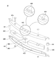
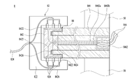
도 13(a)는 본 발명의 스파이더의 단면도를 나타낸 것이다. 도 13(b)는 본 발명의 스파이더의 저면도를 나타낸 것이다. 도 14는 본 발명의 스파이더의 단면도를 확대하여 나타낸 것이다. 도 15(a)는 본 발명의 드럼의 후면을 나타낸 것이다. 도 15(b)는 본 발명의 드럼의 전면을 나타낸 것이다. 도 15(c)는 본 발명의 작동부연결선의 사시도를 나타낸 것이다. 도 16는 본 발명의 와이어가이더의 분해사시도 이다.13 (a) is a sectional view of the spider of the present invention. 13 (b) is a bottom view of the spider of the present invention. 14 is an enlarged view of a cross-sectional view of the spider of the present invention. 15 (a) shows a rear view of the drum of the present invention. 15 (b) shows a front view of the drum of the present invention. Fig. 15 (c) is a perspective view of an operating part connecting line of the present invention. 16 is an exploded perspective view of the wire guider of the present invention.
이하에서 본 발명의 의류처리장치에 구비된 전방밸런서 및 후방밸런서에 전력을 공급하는 구조에 대하여 설명한다.Hereinafter, a structure for supplying power to the front balancer and the rear balancer included in the clothes processing apparatus of the present invention will be described.
본 발명은 밸런서(6)의 작동부(68)에 전력을 공급하기 위한 전력공급부(8)를 더 포함한다.The present invention further includes a power supply unit (8) for supplying power to the operating unit (68) of the balancer (6).
도 13 및 도 14에 도시된 바와 같이, 상기 전력공급부(8)는 외부 전력원(824)에 연결된 제1공급부(82)와 상기 제1공급부(82)에 전기적으로 접촉하되 작동부(68)에 전력을 공급하는 제2공급부(84)로 구비될 수 있다.13 and 14, the
상기 제1공급부(82)는 캐비닛(1) 내부에 고정된 제1바디(822)와, 상기 제1바디(822)에 구비되며, 전기가 흐를 수 있는 전도체로 구비된 제1접촉부(826)를 포함하고, 제1접촉부(826)는 외부 전력원(824)에 연결되어 전력을 공급받는다.The
상기 제1바디(822)는 회전축(56)이 내부로 삽입될 수 있는 원통형으로 구비될 수 있으며, 제1접촉부(826)는 제1바디(822) 내주면에서 돌출되어 탄성을 가지도록 구비될 수 있다. 따라서, 회전축(56)이 회전하더라도 회전축(56)의 외주면에 구비된 제2접촉부(8422)에 지속적으로 전기적 접촉할 수 있다.The
한편, 상기 제2공급부(84)는 회전축(56)에 구비되며, 회전축과 일체로 회전하는 제2바디(842)를 포함한다.Meanwhile, the
상기 제2바디(842)는 전도체로 구비될 수 있으며, 제1접촉부(826)에 전기적으로 접촉하여 전력을 공급받으며, 자세히는 후술할 축관통홀(562) 내부에 구비된 축연결선(8442)에 연결되어 전력을 공급할 수 있다. 이 경우 제2바디(842)는 회전축(56)의 외주면에서 제1접촉부(826)와 접촉하며, 제2바디(842)의 일부가 축관통홀(562)에 삽입되어 축연결선(8442)에 연결된다.The
상기 제2바디(842)의 다른 예에서는 제2바디(842) 자체를 전도체로 구비하는 대신에 상기 제1접촉부(826)에 전기적으로 접촉하고 전도체로 이뤄져 제2바디(842)의 외주면에 구비된 제2접촉부(8422)와, 축관통홀(562)에 삽입되어 축연결선(8442)에 연결되는 전도체인 제3접촉부(8424)와, 제2접촉부(8422)와 제3접촉부(8424)를 연결하는 접촉부연결선(8423)을 포함할 수 있다.In another example of the
상기 제2바디(842)는 회전축(56)의 끝단에 고정하기 위하여 제2바디(842)는 내주면에 나사산을 구비한 원통형상으로 구비되고, 회전축(56)의 외주면에도 나사산을 구비하여 제2바디(842)를 회전축(56)의 외주면에 삽입하여 고정할 수 있다.The
한편, 상기 회전축(56)은 내부에 중공으로 이뤄진 축관통홀(562)과, 상기 축관통홀(562) 내부에 구비된 축연결선(8442)을 포함하며, 상기 축연결선은 상술한 바와 같이 제2바디(842) 또는 제3접촉부(8424)에 연결되어 전력을 공급받으며, 후술할 제1연결선(846)에 연결되어 전력을 공급한다. 또한, 제1연결선(846)은 후방밸런서(6b)의 작동부(68)에 연결되어 전력을 공급하며, 전방밸런서(6a)에 전력을 공급하기 위하여 제1연결선(846)은 제2연결선(866)에 연결되고, 제2연결선(866)은 전방밸런서(6a)의 작동부(68)에 연결되어 전력을 공급할 수 있다.The
본 명세서에서는 설명의 편의를 위하여 축연결선, 제1연결선, 제2연결선으로 전력을 공급하기 위한 전선을 단락지었지만, 실제로는 후방밸런서에 전력을 공급하기 위한 전선을 제1선(미도시), 전방밸런서에 전력을 공급하기 위한 전선을 제2선(미도시)으로 구비할 수도 있다. In the present specification, the wires for supplying electric power to the shaft connecting wire, the first connecting wire and the second connecting wire are short-circuited for convenience of explanation. In practice, however, the electric wire for supplying electric power to the rear balancer is referred to as a first wire (not shown) (Not shown) for supplying power to the front balancer.
상기 축관통홀(562) 내부로 세탁수가 누수되는 것을 방지하고 축관통홀(562)에 축연결선(8442)의 설치를 용이하게 하기 위하여 축관통홀(562)의 내부에 축소켓(844)을 더 포함한다.A
상기 축소켓(844)의 내부에 축연결선(8442)을 구비하고, 양단에는 소켓 형태로 구비되어 조립의 용이성을 돕는다.A
상기 축연결선(8442)은 전방밸런서(6a)에 전력을 공급하는 전방축연결선(8442a)과 후방밸런서(6b)에 전력을 공급하는 후방축연결선(8442b)으로 구비될 수 있으며, 각각 4가닥의 전선(여기서 전선은 전류가 일 방향으로 흐르는 전도체를 말한다.)으로 구비된다. 왜냐하면, 하나의 모터에 전류를 공급하기 위해서는 2가닥의 전선이 필요하고, 밸런서 하나에는 2개의 모터가 있으므로 전방밸런서 또는 후방밸런서에는 각가 4가닥의 전선이 필요하다.The
상기 제1연결선(846)의 일단은 상기 축소켓(844)의 끝단에 구비된 소켓에 삽입되어 연결되는 제1a연결선단자(8462)를 포함하며, 타단은 후방밸런서(6b)와 전방밸런서(6a)로 분지되어 전력을 공급하는 제1b연결선단자(8464)와 제1c연결선단자(8466)가 구비된다. One end of the first connecting
상기 제1연결선(846)은 상기 스파이더(58)에 고정된다. 구체적으로 제1연결선(846)은 하나의 스파이더다리(584)의 일측에 고정된다. The first connecting
도 15(a)에 도시된 바와 같이, 상기 제1연결선(846)은 작동부(68)에 연결되어 전력을 공급한다. 구체적으로는 작동부하우징(62)에 구비된 전력공급소켓(6822)에 연결된다.As shown in FIG. 15 (a), the first connecting
조립의 편의를 위하여 제1연결선(846)의 타단에 구비된 제1b연결선단자(8464)와 작동부하우징(62)에 구비된 전력공급소켓(6822) 사이를 연결하는 작동부연결선(848)을 더 포함할 수 있다. 도 15(c)에 도시된 바와 같이, 작동부연결선(848)는 총 4가닥의 전선으로 구비되며 각각의 2가닥 전선은 2개의 모터에 각각 전력을 공급한다. An operation
한편, 도 16에 도시된 바와 같이, 전방밸런서(6a)에 전력을 공급하기 위하여 제1연결선(846)과 전방밸런서(6a) 사이를 연결하는 제2연결선(866)을 더 포함한다.16, a second connecting
상기 제2연결선(866)은 상기 제1c연결선단자(8466)에 연결되고, 전방밸런서(6a)에 구비된 작동부(68)에 연결된다. 이 경우도 도 15(b)와 같이, 조립의 편의를 위하여 작동부연결선(848)으로 제2연결선(866)과 작동부하우징(62)에 구비된 전력공급소켓(6822) 사이를 연결할 수 있다.The second connecting
한편, 상기 제2연결선(866)은 드럼(4)의 외주면에 구비되므로 드럼의 회전으로 파손될 수 있는 문제가 있다. On the other hand, since the second connecting
이를 해결하기 위하여 본 발명은 드럼(4)의 외주면에 구비되며, 제2연결선(866)을 보호하는 와이어가이더(86)를 더 포함할 수 있다.In order to solve this problem, the present invention may further include a
상기 와어이가이더(86)는 드럼(4)의 길이방향으로 길게 구비되고, 드럼의 외주면에 고정되는 가이더바디(862)와, 가이더바디(862)의 내면에 돌출되어 구비된 고정리브(864)를 포함한다. The
상기 제2연결선(866)은 상기 고정리브(864)에 고정되므로 외부로 노출되지 않도록 한다. The
한편, 제2연결선이 드럼의 외주면에 노출되는 것을 최대한 방지하기 위하여 상기 드럼(4)은, 즉 드럼통(42)과 드럼후면(46)(또는 드럼전면(44))을 관통하는 제3드럼관통홀(422)을 구비하고, 상기 제3드럼관통홀(422)에 연통하는 상기 하우징(62)의 하우징체결돌기(628)에 구비된 제2연결선관통홀(6281)을 구비한다. 따라서, 제2연결선(866)은 제3드럼관통홀(422), 제2연결선관통홀(6281)을 차례로 나서 드럼의 후면에서는 제1연결선(846)에 연결되고, 드럼의 전면에서는 전방밸런서(6a)의 작동부에 연결된다. 즉, 드럼의 드럼통의 외주면에 제2연결선이 노출되는 것을 방지하고, 드럼의 전면이나 후면에서만 노출되도록 하기 위함이다. In order to prevent the second connecting line from being exposed to the outer circumferential surface of the drum as much as possible, the
도 17(a)는 본 발명의 와이어가이더의 다른예의 단면도를 나타낸 것이다. 도 17(b)는 본 발명의 와이어가이더의 다른예의 설치예를 나타낸 것이다.17 (a) shows a cross-sectional view of another example of the wire guider of the present invention. Fig. 17 (b) shows an example of installation of another example of the wire guider of the present invention.
이하에서 도 17을 참조하여 본 발명의 와이어가이더의 다른 예를 설명한다.Hereinafter, another example of the wire guider of the present invention will be described with reference to Fig.
전방밸런서(6a)에 전력을 공급하기 위해서는 앞서 살펴본 바와 같이, 제2연결선(866)을 드럼의 외주면에 구비하여 회전하는 드럼(4)과 고정된 터브의 내주면 사이에서 제2연결선(866)이 파손될 위험이 크다. As described above, the second connecting
이러한 문제를 해결하기 위해 본 발명은 드럼(4)의 외주면에 전선과 같은 와이어(wire)의 소재를 사용하기 않은 와이어가이더(86)의 다른 예를 구비할 수 있다.In order to solve such a problem, the present invention may include another example of the
와이어가이더(86)의 다른 예는 부도체이며, 드럼의 외주면에 구비되는 가이더바디(862)와, 가이더바디(862) 내부에 구비되어 전류가 흐르는 도체로 구비된 전도체(미도시)와, 상기 전도체에 전기적으로 연결되며, 가이더바디(862)의 양단에 구비된 가이더단자(8666)를 포함한다.Another example of the
상기 가이더 단자는 드럼(4) 또는 밸런서의 하우징(62)에 구비된 전력소켓홀(629)에 삽입된다. 상기 전력소켓홀(629)은 드럼의 양단에 구비될 수 있다. 한편, 와이어가이더(86)는 전력소켓홀(629)에 가이더단자(8666)가 삽입된 것만으로도 드럼의 외주면에 고정된다.The guider terminal is inserted into a
상기 전력소켓홀(629)은 내부로 연결되어 가이더단자(8666)와 전기적으로 접촉하며, 제1c연결선단자에 연결되는 전력소켓전선(6291)을 포함한다. 따라서, 상기 가이더단자(8666)가 전력소켓홀(629)에 삽입된 것만으로 제1c연결선단자, 와이어가이더, 전방밸런서까지 전기적으로 연결된 회로를 구성한다.The
본 발명은 다양한 형태로 변형되어 실시될 수 있을 것인바 상술한 실시예에 그 권리범위가 한정되지 않는다. 따라서 변형된 실시예가 본 발명 특허청구범위의 구성요소를 포함하고 있다면 본 발명의 권리범위에 속하는 것으로 보아야 할 것이다.The present invention may be embodied in various forms without departing from the scope of the invention. Accordingly, it is intended that the present invention cover the modifications and variations of this invention provided they come within the scope of the appended claims and their equivalents.
캐비닛1
도어12
제1투입구122
가스켓124
터브2
제2투입구22
스프링24
댐퍼26
급배수부3
급수관31
배수관36
드럼4
드럼통42
드럼전면44
제3투입구442
드럼후면46
제1드럼체결홀480
제2드럼체결홀482
제3드럼관통홀484
구동부5
스테이터52
로터54
회전축56
축관통홀562
스파이더58
스파이더코어582
스파이더다리584
밸런서6
하우징62
수용공간622
제1원면622a
제2원면622b
제1측면622c
제2측면622d
제1격벽622e
리세스626
하우징개구부627
하우징체결돌기628
하우징체결홀6282
제2연결선관통홀6281전력소켓홀629
전력소켓전선6291
밸런싱유닛64
유닛바디642
유닛바디체결홀6422
롤러644, 6442
무게더미646
자성체648
간격유지부649
보조휠6492
링66
제1링66a
제2링66b
기어이빨662
작동부68
작동부하우징682
전력공급소켓6822
제1회전기어6842
제1모터기어6846
제2회전기어6862
제2모터기어6866
연동기어687
제1모터688a
제2모터688b
센싱부7
전력공급부8
제1공급부82
제1바디822
제1접촉부826
젼력원824
제2공급부84
제2바디842
제2접촉부8422
접촉부연결선8423
제3접촉부8424
축연결선8442
제1연결선846
작동부연결선848
와이어가이더86
가이더바디862
고정리브864
제2연결선866
가이더단자8666
Drum rear 46 First
Third drum through
First
2nd connection line through
Balancing
Interval maintaining portion 649
Operating
First rotary gear 6842
A
The second connecting
Claims (14)
상기 캐비닛 내부에 구비되어 세탁수가 저장되는 터브와;
상기 터브 내부에 회전 가능하게 구비되고, 의류가 저장되는 드럼과;
상기 드럼에 고정된 하우징과;
상기 하우징 내부에 구비되며 폐곡선을 형성하는 수용공간과;
상기 수용공간 내부를 이동 가능하게 구비되어 상기 드럼의 언밸런싱 상태를 해소하는 밸런싱유닛과;
상기 밸런싱유닛을 이동시키기 위하여 상기 밸런싱유닛에 연결된 링과;
상기 링을 이동시키기 위하여 구비되는 작동부;를 포함하며,
상기 밸런싱유닛은 상기 수용공간을 따라 360도 회전할 수 있도록 구비된 것을 특징으로 하는 의류처리장치.A cabinet;
A tub disposed inside the cabinet to store wash water;
A drum rotatably installed in the tub and storing clothes;
A housing fixed to the drum;
A housing space provided in the housing and defining a closed curve;
A balancing unit movably installed in the accommodating space to eliminate an unbalanced state of the drum;
A ring coupled to the balancing unit to move the balancing unit;
And an operating portion provided to move the ring,
Wherein the balancing unit is provided to rotate 360 degrees along the accommodation space.
상기 링은 폐곡선을 형성하는 원형 또는 개방곡선으로 형성된 원호의 일부로 구비되는 것을 특징으로 하는 의류처리장치.The method according to claim 1,
Wherein the ring is provided as a part of a circle formed by a circular curve or an opening curve forming a closed curve.
상기 링의 강도는 상기 링의 형상이 상기 밸런싱유닛의 무게에 의해 변형되지 않을 정도의 강도를 가지는 것을 특징으로 하는 의류처리장치.The method according to claim 1,
Wherein the strength of the ring is such that the shape of the ring is not deformed by the weight of the balancing unit.
상기 링은 제1링과 상기 제1링의 하부에 동일한 직경으로 구비되는 제2링을 포함하며, 상기 제1링에는 제1밸런싱유닛이 연결되고, 상기 제2링에는 제2밸런싱유닛이 연결되는 것을 특징으로 하는 의류처리장치.The method according to claim 1,
Wherein the ring comprises a first ring and a second ring having the same diameter at the bottom of the first ring, wherein a first balancing unit is connected to the first ring and a second balancing unit is connected to the second ring, And the clothes processing apparatus.
상기 링은 제1링과 상기 제1링과 다른 직경으로 구비되는 제2링을 포함하며, 상기 제1링에는 제1밸런싱유닛이 연결되고, 상기 제2링에는 제2밸런싱유닛이 연결되는 것을 특징으로 하는 의류처리장치.The method according to claim 1,
The ring includes a first ring and a second ring having a different diameter than the first ring, wherein the first ring is connected to a first balancing unit and the second ring is connected to a second balancing unit Characterized in that it comprises:
상기 링은 링가이드돌기 또는 링가이드홈을 포함하며, 상기 링가이드돌기 또는 링가이드홈에 대응되는 형상으로 상기 수용공간에 구비된 수용공간 홈 또는 수용공간 돌기를 포함하는 것을 특징으로 하는 의류처리장치.The method according to claim 1,
Wherein the ring includes a ring guide protrusion or a ring guide groove and includes a receiving space groove or a receiving space protrusion provided in the receiving space in a shape corresponding to the ring guide protrusion or the ring guide groove. .
상기 링은 상기 작동부에 구비된 회전기어에 맞물려 이동할 수 있도록 상기 링의 표면에 기어이빨을 구비하는 것을 특징으로 하는 의류처리장치.The method according to claim 1,
Wherein the ring is provided with gear teeth on a surface of the ring so that the ring can be engaged with a rotating gear provided in the operating portion.
상기 링은 상기 작동부에 구비된 회전기어에 맞물려 이동할 수 있도록 체인으로 구비되는 것을 특징으로 하는 의류처리장치.The method according to claim 1,
Wherein the ring is provided as a chain so that the ring can be engaged with the rotary gear of the operation unit.
상기 밸런싱유닛은 상기 드럼의 중심축에 대하여 원주방향으로 원호를 이루도록 구비되는 것을 특징으로 하는 의류처리장치.The method according to claim 1,
Wherein the balancing unit is provided so as to be circular in a circumferential direction with respect to a central axis of the drum.
상기 밸런싱유닛은 상기 링의 외주면에 연결되는 것을 특징으로 하는 의류처리장치.The method according to claim 1,
And the balancing unit is connected to the outer peripheral surface of the ring.
상기 밸런싱유닛은 상기 드럼의 회전속도가 소정속도 이상인 경우에 상기 수용공간에 접촉하여 고정되는 것을 특징으로 하는 의류처리장치.The method according to claim 1,
Wherein the balancing unit is fixed in contact with the accommodating space when the rotational speed of the drum is equal to or higher than a predetermined speed.
상기 수용공간 내부에서 상기 밸런싱유닛의 이동을 원활하게 하기 위하여 상기 밸런싱유닛의 양단에 구비된 롤러;을 포함하는 것을 특징으로 하는 의류처리장치.The method according to claim 1,
And a roller provided at both ends of the balancing unit to smoothly move the balancing unit in the accommodating space.
상기 수용공간과 상기 밸런싱유닛을 이격시키기 위하여 상기 밸런싱유닛 또는 상기 수용공간의 내부 측면에 구비되는 간격유지부;를 포함하는 것을 특징으로 하는 의류처리장치.The method according to claim 1,
And a gap holding part provided on an inner side surface of the accommodation space or the balancing unit to separate the accommodation space from the balancing unit.
상기 밸런싱유닛에 구비된 자성체와;
상기 자성체의 자성을 감지할 수 있도록 상기 터브 또는 상기 캐비닛에 구비된 센싱부;를 포함하는 것을 특징으로 하는 의류처리장치.The method according to claim 1,
A magnetic body provided in the balancing unit;
And a sensing unit provided in the tub or the cabinet so as to sense the magnetism of the magnetic body.
Priority Applications (4)
| Application Number | Priority Date | Filing Date | Title |
|---|---|---|---|
| KR1020150109620A KR102390032B1 (en) | 2015-08-03 | 2015-08-03 | Laundry Treating Apparatus |
| EP16833282.3A EP3333301B1 (en) | 2015-08-03 | 2016-07-29 | Clothes processing device |
| US15/749,958 US10801152B2 (en) | 2015-08-03 | 2016-07-29 | Clothes processing device |
| PCT/KR2016/008398 WO2017023046A1 (en) | 2015-08-03 | 2016-07-29 | Clothes processing device |
Applications Claiming Priority (1)
| Application Number | Priority Date | Filing Date | Title |
|---|---|---|---|
| KR1020150109620A KR102390032B1 (en) | 2015-08-03 | 2015-08-03 | Laundry Treating Apparatus |
Publications (2)
| Publication Number | Publication Date |
|---|---|
| KR20170016184A true KR20170016184A (en) | 2017-02-13 |
| KR102390032B1 KR102390032B1 (en) | 2022-04-25 |
Family
ID=58156115
Family Applications (1)
| Application Number | Title | Priority Date | Filing Date |
|---|---|---|---|
| KR1020150109620A KR102390032B1 (en) | 2015-08-03 | 2015-08-03 | Laundry Treating Apparatus |
Country Status (1)
| Country | Link |
|---|---|
| KR (1) | KR102390032B1 (en) |
Citations (4)
| Publication number | Priority date | Publication date | Assignee | Title |
|---|---|---|---|---|
| KR20040000865A (en) * | 2002-06-26 | 2004-01-07 | 주식회사 대우일렉트로닉스 | A weight unbalance sensing device for washing machine |
| KR20130013061A (en) * | 2011-07-27 | 2013-02-06 | 삼성전자주식회사 | Washing machine and balancer thereof |
| US20130133475A1 (en) * | 2010-08-13 | 2013-05-30 | Safedin Zelic | Annular auto-balancing mechanism |
| KR20130114478A (en) * | 2012-04-09 | 2013-10-18 | 엘지전자 주식회사 | Washing machine |
-
2015
- 2015-08-03 KR KR1020150109620A patent/KR102390032B1/en active IP Right Grant
Patent Citations (4)
| Publication number | Priority date | Publication date | Assignee | Title |
|---|---|---|---|---|
| KR20040000865A (en) * | 2002-06-26 | 2004-01-07 | 주식회사 대우일렉트로닉스 | A weight unbalance sensing device for washing machine |
| US20130133475A1 (en) * | 2010-08-13 | 2013-05-30 | Safedin Zelic | Annular auto-balancing mechanism |
| KR20130013061A (en) * | 2011-07-27 | 2013-02-06 | 삼성전자주식회사 | Washing machine and balancer thereof |
| KR20130114478A (en) * | 2012-04-09 | 2013-10-18 | 엘지전자 주식회사 | Washing machine |
Also Published As
| Publication number | Publication date |
|---|---|
| KR102390032B1 (en) | 2022-04-25 |
Similar Documents
| Publication | Publication Date | Title |
|---|---|---|
| EP3333301B1 (en) | Clothes processing device | |
| EP2956579B1 (en) | Laundry treatment apparatus | |
| BR112014002903B1 (en) | WASHING MACHINE | |
| KR20140145431A (en) | Laundry Treating Apparatus | |
| KR102218909B1 (en) | Laundry Treating Apparatus | |
| CN114846194B (en) | Laundry appliance with dynamic balancing assembly | |
| US11697900B2 (en) | Suspensionless laundry apparatuses and methods of balancing a laundry apparatus | |
| JP6396509B2 (en) | Clothing processing equipment | |
| KR20130114478A (en) | Washing machine | |
| KR20130114482A (en) | Washing machine | |
| KR20150052454A (en) | Balancer and washing machine having the same | |
| US11655579B2 (en) | Dynamic balancing assemblies and laundry apparatuses having one or more clocksprings | |
| KR102329421B1 (en) | Laundry Treating Apparatus | |
| US20180044836A1 (en) | Clothes treating apparatus | |
| KR20170016184A (en) | Laundry Treating Apparatus | |
| KR20170016185A (en) | Laundry Treating Apparatus | |
| KR102330525B1 (en) | Laundry Treating Apparatus | |
| KR102218911B1 (en) | Laundry Treating Apparatus | |
| KR102578446B1 (en) | Washing Machine | |
| CN114846192B (en) | Dynamic balancing assembly with one or more springs and laundry appliance | |
| US20210207310A1 (en) | Laundry processing apparatus | |
| KR20220031350A (en) | Laundary treating apparatus | |
| KR102218910B1 (en) | Laundry Treating Apparatus | |
| KR20160117949A (en) | Laundry Treating Apparatus and Control Method for the same |
Legal Events
| Date | Code | Title | Description |
|---|---|---|---|
| A201 | Request for examination | ||
| E902 | Notification of reason for refusal | ||
| E701 | Decision to grant or registration of patent right | ||
| GRNT | Written decision to grant |