KR20170014741A - Smart plug in intelligent transportation system and transportation apparauts management server - Google Patents
Smart plug in intelligent transportation system and transportation apparauts management server Download PDFInfo
- Publication number
- KR20170014741A KR20170014741A KR1020150108578A KR20150108578A KR20170014741A KR 20170014741 A KR20170014741 A KR 20170014741A KR 1020150108578 A KR1020150108578 A KR 1020150108578A KR 20150108578 A KR20150108578 A KR 20150108578A KR 20170014741 A KR20170014741 A KR 20170014741A
- Authority
- KR
- South Korea
- Prior art keywords
- traffic equipment
- power
- sensor
- traffic
- information
- Prior art date
Links
- 238000001514 detection method Methods 0.000 claims abstract description 22
- 238000004891 communication Methods 0.000 claims description 24
- 238000000034 method Methods 0.000 claims description 10
- 230000005856 abnormality Effects 0.000 claims description 4
- 239000000779 smoke Substances 0.000 claims description 4
- 238000004458 analytical method Methods 0.000 claims description 3
- 238000007726 management method Methods 0.000 description 40
- 238000005259 measurement Methods 0.000 description 9
- 230000006870 function Effects 0.000 description 7
- 238000010586 diagram Methods 0.000 description 6
- 230000005611 electricity Effects 0.000 description 5
- 238000005516 engineering process Methods 0.000 description 5
- 230000002159 abnormal effect Effects 0.000 description 4
- 238000012544 monitoring process Methods 0.000 description 4
- 230000007257 malfunction Effects 0.000 description 3
- CURLTUGMZLYLDI-UHFFFAOYSA-N Carbon dioxide Chemical compound O=C=O CURLTUGMZLYLDI-UHFFFAOYSA-N 0.000 description 2
- 230000000694 effects Effects 0.000 description 2
- 238000012986 modification Methods 0.000 description 2
- 230000004048 modification Effects 0.000 description 2
- OKTJSMMVPCPJKN-UHFFFAOYSA-N Carbon Chemical compound [C] OKTJSMMVPCPJKN-UHFFFAOYSA-N 0.000 description 1
- 241001112258 Moca Species 0.000 description 1
- 238000003491 array Methods 0.000 description 1
- 229910052799 carbon Inorganic materials 0.000 description 1
- 229910002092 carbon dioxide Inorganic materials 0.000 description 1
- 239000001569 carbon dioxide Substances 0.000 description 1
- 230000008859 change Effects 0.000 description 1
- 238000004590 computer program Methods 0.000 description 1
- 230000001419 dependent effect Effects 0.000 description 1
- 230000007717 exclusion Effects 0.000 description 1
- 238000007689 inspection Methods 0.000 description 1
- 238000012806 monitoring device Methods 0.000 description 1
- 230000003287 optical effect Effects 0.000 description 1
- 230000008569 process Effects 0.000 description 1
- 230000001012 protector Effects 0.000 description 1
- 239000013643 reference control Substances 0.000 description 1
- 238000012546 transfer Methods 0.000 description 1
- 230000007723 transport mechanism Effects 0.000 description 1
Images


Classifications
-
- G—PHYSICS
- G01—MEASURING; TESTING
- G01R—MEASURING ELECTRIC VARIABLES; MEASURING MAGNETIC VARIABLES
- G01R31/00—Arrangements for testing electric properties; Arrangements for locating electric faults; Arrangements for electrical testing characterised by what is being tested not provided for elsewhere
- G01R31/005—Testing of electric installations on transport means
-
- G—PHYSICS
- G01—MEASURING; TESTING
- G01R—MEASURING ELECTRIC VARIABLES; MEASURING MAGNETIC VARIABLES
- G01R11/00—Electromechanical arrangements for measuring time integral of electric power or current, e.g. of consumption
- G01R11/02—Constructional details
- G01R11/25—Arrangements for indicating or signalling faults
-
- G01R31/024—
-
- G—PHYSICS
- G01—MEASURING; TESTING
- G01R—MEASURING ELECTRIC VARIABLES; MEASURING MAGNETIC VARIABLES
- G01R31/00—Arrangements for testing electric properties; Arrangements for locating electric faults; Arrangements for electrical testing characterised by what is being tested not provided for elsewhere
- G01R31/12—Testing dielectric strength or breakdown voltage ; Testing or monitoring effectiveness or level of insulation, e.g. of a cable or of an apparatus, for example using partial discharge measurements; Electrostatic testing
-
- G—PHYSICS
- G06—COMPUTING; CALCULATING OR COUNTING
- G06Q—INFORMATION AND COMMUNICATION TECHNOLOGY [ICT] SPECIALLY ADAPTED FOR ADMINISTRATIVE, COMMERCIAL, FINANCIAL, MANAGERIAL OR SUPERVISORY PURPOSES; SYSTEMS OR METHODS SPECIALLY ADAPTED FOR ADMINISTRATIVE, COMMERCIAL, FINANCIAL, MANAGERIAL OR SUPERVISORY PURPOSES, NOT OTHERWISE PROVIDED FOR
- G06Q50/00—Information and communication technology [ICT] specially adapted for implementation of business processes of specific business sectors, e.g. utilities or tourism
- G06Q50/10—Services
-
- G06Q50/30—
-
- G—PHYSICS
- G08—SIGNALLING
- G08B—SIGNALLING OR CALLING SYSTEMS; ORDER TELEGRAPHS; ALARM SYSTEMS
- G08B21/00—Alarms responsive to a single specified undesired or abnormal condition and not otherwise provided for
- G08B21/18—Status alarms
- G08B21/182—Level alarms, e.g. alarms responsive to variables exceeding a threshold
-
- G—PHYSICS
- G08—SIGNALLING
- G08B—SIGNALLING OR CALLING SYSTEMS; ORDER TELEGRAPHS; ALARM SYSTEMS
- G08B21/00—Alarms responsive to a single specified undesired or abnormal condition and not otherwise provided for
- G08B21/18—Status alarms
- G08B21/185—Electrical failure alarms
-
- G—PHYSICS
- G08—SIGNALLING
- G08G—TRAFFIC CONTROL SYSTEMS
- G08G1/00—Traffic control systems for road vehicles
- G08G1/097—Supervising of traffic control systems, e.g. by giving an alarm if two crossing streets have green light simultaneously
-
- H—ELECTRICITY
- H02—GENERATION; CONVERSION OR DISTRIBUTION OF ELECTRIC POWER
- H02H—EMERGENCY PROTECTIVE CIRCUIT ARRANGEMENTS
- H02H7/00—Emergency protective circuit arrangements specially adapted for specific types of electric machines or apparatus or for sectionalised protection of cable or line systems, and effecting automatic switching in the event of an undesired change from normal working conditions
- H02H7/20—Emergency protective circuit arrangements specially adapted for specific types of electric machines or apparatus or for sectionalised protection of cable or line systems, and effecting automatic switching in the event of an undesired change from normal working conditions for electronic equipment
Landscapes
- General Physics & Mathematics (AREA)
- Physics & Mathematics (AREA)
- Business, Economics & Management (AREA)
- Engineering & Computer Science (AREA)
- Tourism & Hospitality (AREA)
- Emergency Management (AREA)
- Economics (AREA)
- Health & Medical Sciences (AREA)
- Operations Research (AREA)
- General Health & Medical Sciences (AREA)
- Human Resources & Organizations (AREA)
- Marketing (AREA)
- Primary Health Care (AREA)
- Strategic Management (AREA)
- General Business, Economics & Management (AREA)
- Theoretical Computer Science (AREA)
- Power Engineering (AREA)
- Remote Monitoring And Control Of Power-Distribution Networks (AREA)
Abstract
The smart plug in the intelligent traffic system generates a power related information and danger detection information of the traffic equipment based on the sensing signal sensed by the sensor unit, And a control unit for controlling the traffic equipment on the basis of the information provided by the sensor unit, the detection signal sensed by the sensor unit, and the power-related information and the danger detection information generated by the information provision unit.
Description
The present invention relates to a Smart Plug in an intelligent transportation system and a traffic equipment management server associated therewith.
In order to efficiently adjust traffic congestion and improve stability, it is necessary to integrate advanced technologies such as roads, vehicles, and signal systems into the components of existing traffic systems to make each component work organically The system is called the Intelligent Transport System (ITS).
When such an intelligent traffic system is constructed, vehicle detectors installed on the roads and closed circuit TVs can automatically recognize the traffic information of the sections and the detour information. It can be computed at the operation center and provided to the user through the electric signboard of the road, the Internet, and a mobile phone.
As a result, it is possible to expect an effect of reducing the problems such as traffic congestion, and at the same time, energy saving and low carbon emission effect can be expected.
However, traffic system equipment installed and operated on the road is not a matter of how much electric power is consumed, except for some sites, where a flat fee to which electric power charges are applied uniformly is not important, so actual power consumption measurement is performed There is no problem.
In addition, for example, a bus information terminal (BIT) is supplied even at the night time when the bus is not operated, and traffic is collected and operated in the middle of the night when there is almost no traffic. As time goes on, unnecessary power is consumed.
Particularly, since functions such as power supply measurement, management, and power shutdown are not implemented in the center, unnecessary power is consumed as power is continuously supplied even when a device such as a network fails.
In this way, the power management of the traffic equipments installed on the road is not efficiently managed, and thus it is necessary to develop an energy management system (EMS) applicable to the intelligent transportation system.
In other words, as the energy policy paradigm centered on demand management changes, a variety of energy efficiency technologies are being developed, which are converging ICTs around the world, but they are not being applied in the field of intelligent transportation systems.
Therefore, it is necessary to develop an energy management system specialized in the intelligent transportation system field for efficient use of electric power of the transportation equipment installed in the road network and connected to the central center.
In addition, the power safety management of the field equipment of most intelligent transportation systems currently depends on only the earth leakage breaker which cuts off the current during the overvoltage, and it is impossible to monitor the earth leakage and the earth leakage, It must be dependent on inspection.
Accordingly, there is a disadvantage that it is difficult to prevent risk factors due to short-circuit and over-current in advance.
As another example, various intelligent traffic system facilities are installed for effective traffic operation and safety in the tunnel. However, since the tunnel is exposed to a great risk when a fire occurs, it is necessary to develop a technique to prevent it.
In this regard, in Korean Patent Laid-Open Publication No. 10-2015-0031204 entitled " Management System for Traffic Signal Controller and Server Included therein ", the leakage of a cable connecting a traffic signal controller and a traffic light is monitored in real time And notifies the centralized control center to the central control center.
Embodiments of the present invention provide a smart plug capable of detecting dangerous elements of traffic equipment in real time, collecting and monitoring power measurement information, removing dangerous elements by customized control for various situations, saving energy, Equipment management server.
It should be understood, however, that the technical scope of the present invention is not limited to the above-described technical problems, and other technical problems may exist.
According to a first aspect of the present invention, there is provided a smart plug in a smart traffic system including a sensor unit for sensing an electrical malfunction state of traffic equipment installed on a road, Related information and risk detection information generated by the sensor unit and the information provision unit, based on the sensed signal of the sensor unit, And a control unit for controlling the traffic equipment based on the traffic information.
According to a second aspect of the present invention, there is provided a traffic equipment management server interlocked with a smart plug, comprising a communication module for transmitting and receiving data to and from the smart plug, a memory storing a traffic equipment management program, and a processor for executing the program, The processor receives the sensing signal sensed by the sensor unit and the power related information and the danger sensing information generated by the information providing unit through the communication module as the program is executed, Analyzes the status of the traffic equipment based on the power-related information and the risk detection information, and generates a control signal for controlling the control unit based on the analysis result, and transmits the control signal to the control unit.
According to any one of the above-mentioned objects, a smart plug is installed inside a traffic equipment installed on a road, and detects and collects electric power related conditions and information in real time, thereby reducing power unnecessarily consumed in traffic equipment Can be controlled to be reduced.
In addition, based on the sensing information detected by the sensor included in the smart plug, the safety of the traffic equipment can be detected in real time, thereby reducing the risk of fire in the road facility.
In addition, by monitoring various power information collected in real time on the field, it is possible to efficiently integrate and manage power remotely according to traffic situation, power supply situation, and the like.
1 is a block diagram of a smart plug according to an embodiment of the present invention.
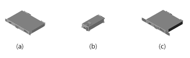
2 is an example of a product type of a smart plug according to an embodiment of the present invention.
3 is a block diagram of a traffic management server according to an embodiment of the present invention.
4 is a diagram illustrating an example of interworking between a smart plug and a traffic equipment management server according to an embodiment of the present invention.
Hereinafter, embodiments of the present invention will be described in detail with reference to the accompanying drawings, which will be readily apparent to those skilled in the art. The present invention may, however, be embodied in many different forms and should not be construed as limited to the embodiments set forth herein. In order to clearly explain the present invention in the drawings, parts not related to the description are omitted.
Whenever a component is referred to as "including" an element throughout the specification, it is to be understood that the element may include other elements, not the exclusion of any other element, unless the context clearly dictates otherwise.
First, a
1 is a block diagram of a
The
The
The first sensor can sense at least one of arc, spark, leakage current, overcurrent, and wire overload occurring in the
According to the detection result of the first sensor, for example, when the power consumption is less than the predetermined minimum power consumption amount, it can be determined that there is an electrical abnormality in the
If it is determined that such an electrical abnormal situation has occurred, the
As described above, the
The second sensor senses the current use amount of the
The third sensor senses the presence of smoke in the
Accordingly, the
The fifth sensor can detect the state of the circuit breaker installed in the
The sensed signals sensed by the first to fifth sensors may be transmitted to the
The
For example, the
The
The
Also, the
The
The
Hereinafter, the product type of the
2 is an illustration of a product type of a
The
Such a
The disconnect device can connect or disconnect the AC input to the output. The circuit breaker includes an overcurrent function that can be shut off automatically when the load current exceeds the allowable current and includes a leakage function that can be shut off automatically if the load leakage current exceeds the allowable value.
The surge protection device can protect the equipment connected to the load from the surge input from the external AC power source. Such a surge protector may consist of a consumable whose function is lost after being protected from surge for a predetermined number of times or more, and may be designed as a replaceable type because it is a consumable.
The power measuring device can measure the power used by the load connected to the AC output from the AC input. The power measurement device can measure voltage, current, power, and electric power, and can transmit data to the
The branch power measurement device can measure the power used in the load connected to each AC output, thereby measuring the voltage, current, and leakage current, and transmitting the data to the
The branch power output control device can control on / off of the power output to the loads connected to the respective AC outputs. With this configuration, the traffic
The branch power arc monitor can monitor the arcs that occur during the use of the load connected to each AC output and can detect and alarm the arcs caused by the problem of the power line connected to the load. In addition, the traffic
The temperature and humidity measuring device can measure temperature and humidity inside the
The DC power supply can supply power to equipment using DC power among external equipment, and the present invention can selectively supply 5V, 9V and 12V according to the embodiment. In addition, the DC power supply can transmit the on-site power state to the center by supplying power to the
The switch operation device provides an output for operating the On switch of the external device and can maintain the contact output for a certain time or more when the power is restored after the power is turned off. In addition, the switch operating device can be turned on by connecting to a power switch of an external PC or the like.
The sensor alarm input device inputs an alarm of an external sensor, and can generate an alarm for each event in conjunction with a sensor such as a door open.
The communication module corresponds to the equipment for transmitting and receiving data with the traffic
Hereinafter, a traffic
3 is a block diagram of a
The traffic
First, the
In the
In addition, the program stored in the
The
Specifically, the traffic
As described above, the traffic
4 is a diagram illustrating an example of interworking of the
The
The
Also, in the case of the car number recognition apparatus and the car detection system, the
As another example, a road sign may be used to save power at nighttime when traffic is low, and in a case of a bus lane and parking train equipment, it may operate in a power saving mode when it is not enforced.
Meanwhile, one or more
1 and 3 according to an embodiment of the present invention may be implemented in hardware such as software or an FPGA (Field Programmable Gate Array) or ASIC (Application Specific Integrated Circuit), and a predetermined Roles can be performed.
However, 'components' are not meant to be limited to software or hardware, and each component may be configured to reside on an addressable storage medium and configured to play one or more processors.
Thus, by way of example, an element may comprise components such as software components, object-oriented software components, class components and task components, processes, functions, attributes, procedures, Routines, segments of program code, drivers, firmware, microcode, circuitry, data, databases, data structures, tables, arrays, and variables.
The components and functions provided within those components may be combined into a smaller number of components or further separated into additional components.
The traffic
While the methods and systems of the present invention have been described in connection with specific embodiments, some or all of those elements or operations may be implemented using a computer system having a general purpose hardware architecture.
It will be understood by those skilled in the art that the foregoing description of the present invention is for illustrative purposes only and that those of ordinary skill in the art can readily understand that various changes and modifications may be made without departing from the spirit or essential characteristics of the present invention. will be. It is therefore to be understood that the above-described embodiments are illustrative in all aspects and not restrictive. For example, each component described as a single entity may be distributed and implemented, and components described as being distributed may also be implemented in a combined form.
The scope of the present invention is defined by the appended claims rather than the detailed description and all changes or modifications derived from the meaning and scope of the claims and their equivalents are to be construed as being included within the scope of the present invention do.
100: Smart plug
110:
120: Information provision
130:
200: Transportation equipment
300: Traffic equipment management server
310: Communication module
320: Memory
330: Processor
Claims (7)
A sensor unit for detecting an electrical fault condition of the traffic equipment installed on the road,
An information providing unit for generating power related information and danger detection information of the traffic equipment based on the sensing signal sensed by the sensor unit,
And a control unit for controlling the traffic equipment based on the sensing signal sensed by the sensor unit and the power related information and the danger detection information generated by the information providing unit.
The sensor unit includes:
A first sensor for detecting at least one of an arc, a spark, a leakage current, an overcurrent, and a wire overload generated in the traffic equipment in real time,
A second sensor for measuring a current use amount of the line and the branch line of the traffic equipment in relation to an allowable current,
A third sensor for detecting the presence or absence of smoke in the traffic equipment,
A fourth sensor for sensing the temperature of the traffic equipment in real time,
And a fifth sensor that detects in real time the state of the breaker installed in the traffic equipment.
Wherein the control unit controls on / off of a negative lower end power supply of the breaker based on a detection amount of a leakage current sensed by the first sensor.
Wherein the control unit monitors the power factor of the traffic equipment based on the sensing signal sensed by the first sensor or the second sensor.
Further comprising a plurality of power outlets set for each channel or group so as to correspond to the traffic equipment,
Wherein the controller controls on / off of a power outlet according to a channel or a group based on a sensing signal sensed by the sensor unit.
And a communication module for transmitting and receiving data to and from the traffic equipment management server,
Wherein the control unit determines that an electrical abnormality has occurred in the traffic equipment when the amount of power contained in the power-related information is out of a predetermined range, and turns off the power of the traffic equipment or reports to the traffic equipment management server.
A communication module for transmitting and receiving data to and from the smart plug,
The traffic equipment management program stores the memory and
And a processor for executing the program,
Wherein the processor is configured to receive the sensing signal sensed by the sensor unit and the power related information and the danger sensing information generated by the information providing unit via the communication module as the program is executed, And a controller for generating a control signal for controlling the control unit based on the analysis result and transmitting the control signal to the control unit.
Priority Applications (1)
| Application Number | Priority Date | Filing Date | Title |
|---|---|---|---|
| KR1020150108578A KR101728530B1 (en) | 2015-07-31 | 2015-07-31 | Smart plug in intelligent transportation system and transportation apparauts management server |
Applications Claiming Priority (1)
| Application Number | Priority Date | Filing Date | Title |
|---|---|---|---|
| KR1020150108578A KR101728530B1 (en) | 2015-07-31 | 2015-07-31 | Smart plug in intelligent transportation system and transportation apparauts management server |
Publications (2)
| Publication Number | Publication Date |
|---|---|
| KR20170014741A true KR20170014741A (en) | 2017-02-08 |
| KR101728530B1 KR101728530B1 (en) | 2017-04-21 |
Family
ID=58155499
Family Applications (1)
| Application Number | Title | Priority Date | Filing Date |
|---|---|---|---|
| KR1020150108578A KR101728530B1 (en) | 2015-07-31 | 2015-07-31 | Smart plug in intelligent transportation system and transportation apparauts management server |
Country Status (1)
| Country | Link |
|---|---|
| KR (1) | KR101728530B1 (en) |
Cited By (4)
| Publication number | Priority date | Publication date | Assignee | Title |
|---|---|---|---|---|
| CN111422088A (en) * | 2020-04-13 | 2020-07-17 | 苏州君洹自动化设备有限公司 | Outage indicating device and electric automobile fill electric pile |
| KR102147758B1 (en) * | 2020-03-13 | 2020-08-25 | 주식회사 제이와이티 | Bus information terminal type remote terminal unit for Easy-maintenance |
| KR102225935B1 (en) * | 2020-12-31 | 2021-03-10 | 주식회사 예향엔지니어링 | System for providing intelligent transport information |
| KR20220108257A (en) | 2021-01-25 | 2022-08-03 | 이정환 | Internet of Thing multifunction integration module system and method for Smart city |
Family Cites Families (1)
| Publication number | Priority date | Publication date | Assignee | Title |
|---|---|---|---|---|
| KR20050039773A (en) * | 2005-02-25 | 2005-04-29 | 정양권 | The management method and a system for traffic units including signal control |
-
2015
- 2015-07-31 KR KR1020150108578A patent/KR101728530B1/en active IP Right Grant
Cited By (5)
| Publication number | Priority date | Publication date | Assignee | Title |
|---|---|---|---|---|
| KR102147758B1 (en) * | 2020-03-13 | 2020-08-25 | 주식회사 제이와이티 | Bus information terminal type remote terminal unit for Easy-maintenance |
| CN111422088A (en) * | 2020-04-13 | 2020-07-17 | 苏州君洹自动化设备有限公司 | Outage indicating device and electric automobile fill electric pile |
| CN111422088B (en) * | 2020-04-13 | 2021-08-31 | 苏州君洹自动化设备有限公司 | Outage indicating device and electric automobile fill electric pile |
| KR102225935B1 (en) * | 2020-12-31 | 2021-03-10 | 주식회사 예향엔지니어링 | System for providing intelligent transport information |
| KR20220108257A (en) | 2021-01-25 | 2022-08-03 | 이정환 | Internet of Thing multifunction integration module system and method for Smart city |
Also Published As
| Publication number | Publication date |
|---|---|
| KR101728530B1 (en) | 2017-04-21 |
Similar Documents
| Publication | Publication Date | Title |
|---|---|---|
| KR101728530B1 (en) | Smart plug in intelligent transportation system and transportation apparauts management server | |
| KR101378573B1 (en) | Junction box for a solar cell module and driving method thereof | |
| CN103066703B (en) | Intelligent SPD (Surge Protective Device) based on internet of things | |
| US10955455B2 (en) | Broken conductor detection and remediation in electric power systems | |
| KR101875267B1 (en) | Charging station for electric vehicles | |
| CN105527567A (en) | High voltage relay adhesion detection circuit of battery management system and detection method | |
| MX2013014525A (en) | Local transformer level grid management systems and methods. | |
| CN105048439A (en) | Power supply control method and device | |
| CN204216675U (en) | Based on power distribution cabinet electric leakage monitoring and the guard system of CAN formula | |
| KR101511061B1 (en) | System for auto recording the state of electrical power and the method thereof | |
| CN106324393A (en) | Online monitoring system for work equipment of intelligent transformer station | |
| KR20200059388A (en) | Electricity Information Management System | |
| KR101422420B1 (en) | Reset type Power Switch that include ELB Auto Recovery Function | |
| CN107367665A (en) | Power supply cable disconnection monitoring and alarming device based on NB-IoT technology | |
| CN204884103U (en) | Cable electronic monitoring alarm devices based on thing networking | |
| KR101865294B1 (en) | System for monitoring security lamp | |
| CN202904791U (en) | High-voltage transmission line remote intelligent supervisory system | |
| CN103248003A (en) | Power input protection device and power input protection method for outdoor comprehensive cabinet | |
| CN112147440A (en) | Abnormal sensing and autonomous alarm system and method for intelligent charging socket | |
| KR102207181B1 (en) | Device for diagnosing breakdown of switchgear using energy harvesting, diagnosing breakdown of switchgear system comprising the same and operating method thereof | |
| JP2016220265A (en) | Power distribution board | |
| KR101303320B1 (en) | Apparrutus and method to inspect obstruction light for flight, and system using thereof | |
| CN105675942A (en) | High-voltage electric energy metering cabinet and method based on real-time monitoring | |
| KR102426935B1 (en) | The power monitoring system of the distribution box in which the complex environment sensor based on cloud is built in | |
| CN202929149U (en) | Short circuit and earth fault indicator for power transmission network |
Legal Events
| Date | Code | Title | Description |
|---|---|---|---|
| A201 | Request for examination | ||
| E701 | Decision to grant or registration of patent right |