KR20170014665A - Control device for chanring/discharging battery - Google Patents
Control device for chanring/discharging battery Download PDFInfo
- Publication number
- KR20170014665A KR20170014665A KR1020150108392A KR20150108392A KR20170014665A KR 20170014665 A KR20170014665 A KR 20170014665A KR 1020150108392 A KR1020150108392 A KR 1020150108392A KR 20150108392 A KR20150108392 A KR 20150108392A KR 20170014665 A KR20170014665 A KR 20170014665A
- Authority
- KR
- South Korea
- Prior art keywords
- electric vehicle
- battery
- power
- electric
- state
- Prior art date
Links
Images


Classifications
-
- B—PERFORMING OPERATIONS; TRANSPORTING
- B60—VEHICLES IN GENERAL
- B60L—PROPULSION OF ELECTRICALLY-PROPELLED VEHICLES; SUPPLYING ELECTRIC POWER FOR AUXILIARY EQUIPMENT OF ELECTRICALLY-PROPELLED VEHICLES; ELECTRODYNAMIC BRAKE SYSTEMS FOR VEHICLES IN GENERAL; MAGNETIC SUSPENSION OR LEVITATION FOR VEHICLES; MONITORING OPERATING VARIABLES OF ELECTRICALLY-PROPELLED VEHICLES; ELECTRIC SAFETY DEVICES FOR ELECTRICALLY-PROPELLED VEHICLES
- B60L53/00—Methods of charging batteries, specially adapted for electric vehicles; Charging stations or on-board charging equipment therefor; Exchange of energy storage elements in electric vehicles
- B60L53/10—Methods of charging batteries, specially adapted for electric vehicles; Charging stations or on-board charging equipment therefor; Exchange of energy storage elements in electric vehicles characterised by the energy transfer between the charging station and the vehicle
- B60L53/14—Conductive energy transfer
-
- B60L11/1811—
-
- B60L11/1816—
-
- B60L11/1861—
-
- B60L11/1877—
-
- B—PERFORMING OPERATIONS; TRANSPORTING
- B60—VEHICLES IN GENERAL
- B60L—PROPULSION OF ELECTRICALLY-PROPELLED VEHICLES; SUPPLYING ELECTRIC POWER FOR AUXILIARY EQUIPMENT OF ELECTRICALLY-PROPELLED VEHICLES; ELECTRODYNAMIC BRAKE SYSTEMS FOR VEHICLES IN GENERAL; MAGNETIC SUSPENSION OR LEVITATION FOR VEHICLES; MONITORING OPERATING VARIABLES OF ELECTRICALLY-PROPELLED VEHICLES; ELECTRIC SAFETY DEVICES FOR ELECTRICALLY-PROPELLED VEHICLES
- B60L53/00—Methods of charging batteries, specially adapted for electric vehicles; Charging stations or on-board charging equipment therefor; Exchange of energy storage elements in electric vehicles
- B60L53/20—Methods of charging batteries, specially adapted for electric vehicles; Charging stations or on-board charging equipment therefor; Exchange of energy storage elements in electric vehicles characterised by converters located in the vehicle
- B60L53/24—Using the vehicle's propulsion converter for charging
-
- H—ELECTRICITY
- H02—GENERATION; CONVERSION OR DISTRIBUTION OF ELECTRIC POWER
- H02M—APPARATUS FOR CONVERSION BETWEEN AC AND AC, BETWEEN AC AND DC, OR BETWEEN DC AND DC, AND FOR USE WITH MAINS OR SIMILAR POWER SUPPLY SYSTEMS; CONVERSION OF DC OR AC INPUT POWER INTO SURGE OUTPUT POWER; CONTROL OR REGULATION THEREOF
- H02M7/00—Conversion of ac power input into dc power output; Conversion of dc power input into ac power output
- H02M7/02—Conversion of ac power input into dc power output without possibility of reversal
- H02M7/04—Conversion of ac power input into dc power output without possibility of reversal by static converters
- H02M7/12—Conversion of ac power input into dc power output without possibility of reversal by static converters using discharge tubes with control electrode or semiconductor devices with control electrode
-
- H—ELECTRICITY
- H02—GENERATION; CONVERSION OR DISTRIBUTION OF ELECTRIC POWER
- H02M—APPARATUS FOR CONVERSION BETWEEN AC AND AC, BETWEEN AC AND DC, OR BETWEEN DC AND DC, AND FOR USE WITH MAINS OR SIMILAR POWER SUPPLY SYSTEMS; CONVERSION OF DC OR AC INPUT POWER INTO SURGE OUTPUT POWER; CONTROL OR REGULATION THEREOF
- H02M7/00—Conversion of ac power input into dc power output; Conversion of dc power input into ac power output
- H02M7/42—Conversion of dc power input into ac power output without possibility of reversal
- H02M7/44—Conversion of dc power input into ac power output without possibility of reversal by static converters
- H02M7/48—Conversion of dc power input into ac power output without possibility of reversal by static converters using discharge tubes with control electrode or semiconductor devices with control electrode
-
- B—PERFORMING OPERATIONS; TRANSPORTING
- B60—VEHICLES IN GENERAL
- B60L—PROPULSION OF ELECTRICALLY-PROPELLED VEHICLES; SUPPLYING ELECTRIC POWER FOR AUXILIARY EQUIPMENT OF ELECTRICALLY-PROPELLED VEHICLES; ELECTRODYNAMIC BRAKE SYSTEMS FOR VEHICLES IN GENERAL; MAGNETIC SUSPENSION OR LEVITATION FOR VEHICLES; MONITORING OPERATING VARIABLES OF ELECTRICALLY-PROPELLED VEHICLES; ELECTRIC SAFETY DEVICES FOR ELECTRICALLY-PROPELLED VEHICLES
- B60L2210/00—Converter types
- B60L2210/30—AC to DC converters
-
- B—PERFORMING OPERATIONS; TRANSPORTING
- B60—VEHICLES IN GENERAL
- B60L—PROPULSION OF ELECTRICALLY-PROPELLED VEHICLES; SUPPLYING ELECTRIC POWER FOR AUXILIARY EQUIPMENT OF ELECTRICALLY-PROPELLED VEHICLES; ELECTRODYNAMIC BRAKE SYSTEMS FOR VEHICLES IN GENERAL; MAGNETIC SUSPENSION OR LEVITATION FOR VEHICLES; MONITORING OPERATING VARIABLES OF ELECTRICALLY-PROPELLED VEHICLES; ELECTRIC SAFETY DEVICES FOR ELECTRICALLY-PROPELLED VEHICLES
- B60L2210/00—Converter types
- B60L2210/40—DC to AC converters
-
- B—PERFORMING OPERATIONS; TRANSPORTING
- B60—VEHICLES IN GENERAL
- B60L—PROPULSION OF ELECTRICALLY-PROPELLED VEHICLES; SUPPLYING ELECTRIC POWER FOR AUXILIARY EQUIPMENT OF ELECTRICALLY-PROPELLED VEHICLES; ELECTRODYNAMIC BRAKE SYSTEMS FOR VEHICLES IN GENERAL; MAGNETIC SUSPENSION OR LEVITATION FOR VEHICLES; MONITORING OPERATING VARIABLES OF ELECTRICALLY-PROPELLED VEHICLES; ELECTRIC SAFETY DEVICES FOR ELECTRICALLY-PROPELLED VEHICLES
- B60L2220/00—Electrical machine types; Structures or applications thereof
- B60L2220/50—Structural details of electrical machines
- B60L2220/54—Windings for different functions
-
- B60L2230/32—
-
- H02M2001/0006—
-
- Y—GENERAL TAGGING OF NEW TECHNOLOGICAL DEVELOPMENTS; GENERAL TAGGING OF CROSS-SECTIONAL TECHNOLOGIES SPANNING OVER SEVERAL SECTIONS OF THE IPC; TECHNICAL SUBJECTS COVERED BY FORMER USPC CROSS-REFERENCE ART COLLECTIONS [XRACs] AND DIGESTS
- Y02—TECHNOLOGIES OR APPLICATIONS FOR MITIGATION OR ADAPTATION AGAINST CLIMATE CHANGE
- Y02T—CLIMATE CHANGE MITIGATION TECHNOLOGIES RELATED TO TRANSPORTATION
- Y02T10/00—Road transport of goods or passengers
- Y02T10/60—Other road transportation technologies with climate change mitigation effect
- Y02T10/64—Electric machine technologies in electromobility
-
- Y—GENERAL TAGGING OF NEW TECHNOLOGICAL DEVELOPMENTS; GENERAL TAGGING OF CROSS-SECTIONAL TECHNOLOGIES SPANNING OVER SEVERAL SECTIONS OF THE IPC; TECHNICAL SUBJECTS COVERED BY FORMER USPC CROSS-REFERENCE ART COLLECTIONS [XRACs] AND DIGESTS
- Y02—TECHNOLOGIES OR APPLICATIONS FOR MITIGATION OR ADAPTATION AGAINST CLIMATE CHANGE
- Y02T—CLIMATE CHANGE MITIGATION TECHNOLOGIES RELATED TO TRANSPORTATION
- Y02T10/00—Road transport of goods or passengers
- Y02T10/60—Other road transportation technologies with climate change mitigation effect
- Y02T10/70—Energy storage systems for electromobility, e.g. batteries
-
- Y—GENERAL TAGGING OF NEW TECHNOLOGICAL DEVELOPMENTS; GENERAL TAGGING OF CROSS-SECTIONAL TECHNOLOGIES SPANNING OVER SEVERAL SECTIONS OF THE IPC; TECHNICAL SUBJECTS COVERED BY FORMER USPC CROSS-REFERENCE ART COLLECTIONS [XRACs] AND DIGESTS
- Y02—TECHNOLOGIES OR APPLICATIONS FOR MITIGATION OR ADAPTATION AGAINST CLIMATE CHANGE
- Y02T—CLIMATE CHANGE MITIGATION TECHNOLOGIES RELATED TO TRANSPORTATION
- Y02T10/00—Road transport of goods or passengers
- Y02T10/60—Other road transportation technologies with climate change mitigation effect
- Y02T10/7072—Electromobility specific charging systems or methods for batteries, ultracapacitors, supercapacitors or double-layer capacitors
-
- Y—GENERAL TAGGING OF NEW TECHNOLOGICAL DEVELOPMENTS; GENERAL TAGGING OF CROSS-SECTIONAL TECHNOLOGIES SPANNING OVER SEVERAL SECTIONS OF THE IPC; TECHNICAL SUBJECTS COVERED BY FORMER USPC CROSS-REFERENCE ART COLLECTIONS [XRACs] AND DIGESTS
- Y02—TECHNOLOGIES OR APPLICATIONS FOR MITIGATION OR ADAPTATION AGAINST CLIMATE CHANGE
- Y02T—CLIMATE CHANGE MITIGATION TECHNOLOGIES RELATED TO TRANSPORTATION
- Y02T10/00—Road transport of goods or passengers
- Y02T10/60—Other road transportation technologies with climate change mitigation effect
- Y02T10/72—Electric energy management in electromobility
-
- Y—GENERAL TAGGING OF NEW TECHNOLOGICAL DEVELOPMENTS; GENERAL TAGGING OF CROSS-SECTIONAL TECHNOLOGIES SPANNING OVER SEVERAL SECTIONS OF THE IPC; TECHNICAL SUBJECTS COVERED BY FORMER USPC CROSS-REFERENCE ART COLLECTIONS [XRACs] AND DIGESTS
- Y02—TECHNOLOGIES OR APPLICATIONS FOR MITIGATION OR ADAPTATION AGAINST CLIMATE CHANGE
- Y02T—CLIMATE CHANGE MITIGATION TECHNOLOGIES RELATED TO TRANSPORTATION
- Y02T90/00—Enabling technologies or technologies with a potential or indirect contribution to GHG emissions mitigation
- Y02T90/10—Technologies relating to charging of electric vehicles
- Y02T90/12—Electric charging stations
-
- Y—GENERAL TAGGING OF NEW TECHNOLOGICAL DEVELOPMENTS; GENERAL TAGGING OF CROSS-SECTIONAL TECHNOLOGIES SPANNING OVER SEVERAL SECTIONS OF THE IPC; TECHNICAL SUBJECTS COVERED BY FORMER USPC CROSS-REFERENCE ART COLLECTIONS [XRACs] AND DIGESTS
- Y02—TECHNOLOGIES OR APPLICATIONS FOR MITIGATION OR ADAPTATION AGAINST CLIMATE CHANGE
- Y02T—CLIMATE CHANGE MITIGATION TECHNOLOGIES RELATED TO TRANSPORTATION
- Y02T90/00—Enabling technologies or technologies with a potential or indirect contribution to GHG emissions mitigation
- Y02T90/10—Technologies relating to charging of electric vehicles
- Y02T90/14—Plug-in electric vehicles
Abstract
Description
본 발명은 배터리 충방전 제어장치에 관한 것이다. 특히, 전기 자동차(Electric Vehicle) 및 플러그인 하이브리드 자동차(Plug-in hybrid vehicle)에 적용되는 전력변환장치 및 그의 제어 방법에 관한 것이다.The present invention relates to a battery charge / discharge control device. And more particularly, to a power conversion apparatus and a control method thereof applied to an electric vehicle and a plug-in hybrid vehicle.
전기 자동차란, 전기를 사용하여 운행되는 자동차를 의미하는 것으로, 크게 순수 전기 자동차(Batttery Powered Electric Vehicle)와 하이브리드 전기 자동차(Hybrid Electric Vehicle)로 구분될 수 있다. 여기서 순수 전기 자동차는, 화석 연료를 이용함 없이 전기만을 사용하여 주행하는 자동차로서, 일반적으로 전기 자동차라 명칭된다. 그리고 하이브리드 전기 자동차는 전기 및 화석 연료를 사용하여 주행하는 것을 의미한다. 그리고 이와 같은 전기 자동차에는, 주행을 위한 전기를 공급하는 배터리가 구비된다. 특히, 순수 전기 자동차 및 플러그인(Plug-in) 타입의 하이브리드 전기 자동차는, 외부의 전원으로부터 공급되는 전력을 이용하여 배터리를 충전하며, 배터리에 충전된 전력을 이용하여 전기 모터를 구동한다.An electric vehicle is an automobile that is operated by electricity. The electric vehicle can be classified into a pure electric vehicle (Batttery Powered Electric Vehicle) and a hybrid electric vehicle (Hybrid Electric Vehicle). Here, a pure electric vehicle is an automobile that travels only by using electricity without using fossil fuel, and is generally called an electric vehicle. And hybrid electric vehicles are meant to run on electricity and fossil fuels. Such an electric vehicle is provided with a battery for supplying electricity for running. Particularly, a pure electric vehicle and a plug-in type hybrid electric vehicle charge a battery using electric power supplied from an external power source and drive an electric motor using electric power charged in the battery.
이때, 전기 자동차의 운행시 배터리의 직류를 전동기의 회전에너지로 변환하기 위해서 직류를 교류로 변환하는 전력변환장치가 필수적이다. 또한, 정차시 충전을 위해서 전력계통의 교류 에너지를 배터리 충전을 위한 직류로 변환하는 전력변환장치가 필요하다. 따라서 본 발명의 일 실시 예는 하나의 전력변환장치와 전동기를 이용하여 충전 시 연결구조의 변경을 통해 전기자동차의 운행/충전에 필요한 모든 기능을 수행할 수 있는 전기자동차의 전력변환장치를 제안한다.In this case, in order to convert the direct current of the battery into the rotational energy of the electric motor when the electric vehicle is operated, a power conversion device for converting direct current into alternating current is essential. Further, there is a need for a power converter for converting alternating current energy of a power system into direct current for battery charging for charging at a stop. Accordingly, an embodiment of the present invention proposes a power conversion device of an electric vehicle capable of performing all the functions necessary for operation / charging of an electric vehicle by changing the connection structure during charging using one electric power conversion device and an electric motor .
본 발명의 일 실시 예에 따른 전기자동차의 전력변환장치는 중복된 전력변환의 기능을 갖는 인버터와 충전기를 하나의 구성으로 하는 것을 목적으로 한다.The electric power conversion apparatus of an electric vehicle according to an embodiment of the present invention has a configuration in which an inverter and a charger having a redundant power conversion function are constituted.
또한, 본 발명의 일 실시 예에 따른 전기자동차의 전력변환장치는 인버터와 충전기를 하나의 구성으로 하여, 원가를 절감하는 것을 목적으로 한다.In addition, the electric power conversion apparatus of an electric vehicle according to an embodiment of the present invention has an inverter and a charger as one constitution, and aims at cost reduction.
또한, 본 발명의 일 실시 예에 다른 전기자동차의 전력변환장치는 인버터와 충전기를 하나의 구성으로 하여, 무게 및 부피를 절감하는 것을 목적으로 한다. In another aspect of the present invention, there is provided a power conversion apparatus for an electric vehicle, the inverter and the charger having a single structure, thereby reducing weight and volume.
본 발명의 일 실시 예에 따른 전기자동차의 배터리 충방전 제어장치는 전기 에너지로 구동하는 전동기, 전기 에너지를 저장하는 배터리, 전력 계통과 배터리를 연결하는 전기자동차 인렛, 상기 배터리를 상기 전동기 및 전기자동차 인렛 중 어느 하나와 선택적으로 연결하기 위한 릴레이를 포함하고, 상기 배터리로부터 방전되는 직류 전력을 교류 전력으로 변환하는 제1 전력변환장치 및 상기 전기자동차 인렛 또는 전동기로부터 전달되는 교류 전력을 직류 전력으로 변환하는 제2 변환장치를 포함하는 통합전력변환장치 및 및 전기자동차의 상태를 판단하고, 판단 결과에 따라 상기 전력변환장치를 제어하는 제어부를 포함한다.An apparatus for controlling charge / discharge of a battery of an electric vehicle according to an embodiment of the present invention includes an electric motor driven by electric energy, a battery storing electric energy, an electric vehicle inlet connecting a power system and a battery, And a relay for selectively connecting to any one of the inlet, the inlet, the inlet, the inlet, and the inlet of the electric vehicle, the first electric power converter converting the DC power discharged from the battery into the AC power, And a control unit for determining the state of the electric vehicle and controlling the electric power conversion apparatus according to a result of the determination.
이때, 상기 전기자동차의 상태는 주행 상태, 제동 상태 및 충전 상태 중 적어도 하나일 수 있다.At this time, the state of the electric vehicle may be at least one of a traveling state, a braking state, and a charging state.
이때, 상기 통합전력변환장치는 필터구성을 위한 캐패시터를 더 포함할 수 있다.At this time, the integrated power conversion apparatus may further include a capacitor for constituting a filter.
이때, 상기 제어부는 현재 전기자동차의 상태가 주행 상태 또는 제동 상태로 판단된 경우, 상기 배터리와 전동기를 연결하도록 상기 릴레이를 제어할 수 있다.The controller may control the relay to connect the battery and the motor when the current state of the electric vehicle is determined as a running state or a braking state.
이때, 상기 제어부는 현재 전기자동차의 상태가 충전 상태로 판단된 경우, 상기 배터리와 전기자동차 인렛을 연결하도록 상기 릴레이를 제어할 수 있다. At this time, if the current state of the electric vehicle is determined to be a charged state, the controller may control the relay to connect the battery and the electric vehicle inlet.
본 발명의 일 실시 예에 따른 전기자동차의 전력변환장치는 중복된 전력변환의 기능을 갖는 인버터와 충전기를 하나의 구성으로 할 수 있다.The electric power conversion apparatus of an electric vehicle according to an embodiment of the present invention may have one configuration including an inverter and a charger having a redundant power conversion function.
또한, 본 발명의 일 실시 예에 따른 전기자동차의 전력변환장치는 인버터와 충전기를 하나의 구성으로 하여, 원가를 절감할 수 있다.In addition, the electric power conversion apparatus of an electric vehicle according to an embodiment of the present invention can have a single configuration of an inverter and a charger, thereby reducing a cost.
또한, 본 발명의 일 실시 예에 다른 전기자동차의 전력변환장치는 인버터와 충전기를 하나의 구성으로 하여, 무게 및 부피를 절감할 수 있다. In addition, the electric power conversion apparatus of an electric vehicle according to an embodiment of the present invention may have one inverter and a charger, thereby reducing weight and volume.
도 1은 본 발명의 일 실시예에 따른 전기 자동차의 충전 시스템의 개념도이다.
도 2는 본 발명의 일 실시예에 따른 전기 자동차의 블록도이다.
도 3은 기존의 전기자동차의 구성을 나타내는 블록도이다.
도 4는 본 발명의 일 실시 예에 따른 전기자동차를 나타내는 블록도이다.
도 5는 도 4에 도시된 전기자동차 충전 시스템을 도시한 회로도이다.
도 6 내지 도 7은 도 5에 도시된 릴레이의 동작에 따른 전력변환장치의 회로를 나타낸다.
도 8은 본 발명의 일 실시 예에 따른 전기자동차의 전력변환장치의 동작을 나타내는 흐름도이다.1 is a conceptual diagram of a charging system for an electric vehicle according to an embodiment of the present invention.
2 is a block diagram of an electric vehicle according to an embodiment of the present invention.
3 is a block diagram showing a configuration of a conventional electric vehicle.
4 is a block diagram illustrating an electric vehicle according to an embodiment of the present invention.
5 is a circuit diagram showing the electric vehicle charging system shown in FIG.
6 to 7 show the circuit of the power converter according to the operation of the relay shown in Fig.
8 is a flowchart showing the operation of the electric power converter of an electric vehicle according to an embodiment of the present invention.
이하, 본 발명과 관련된 실시예에 대하여 도면을 참조하여 보다 상세하게 설명한다. 이하의 설명에서 사용되는 구성요소에 대한 접미사 "모듈" 및 "부"는 명세서 작성의 용이함만이 고려되어 부여되거나 혼용되는 것으로서, 그 자체로 서로 구별되는 의미 또는 역할을 갖는 것은 아니다. Hereinafter, embodiments related to the present invention will be described in detail with reference to the drawings. The suffix "module" and " part "for the components used in the following description are given or mixed in consideration of ease of specification, and do not have their own meaning or role.
이하에서는 본 발명에 의한 전기 자동차의 충전 시스템의 제1실시예를 첨부된 도면을 참조하여 보다 상세하게 설명한다.
Hereinafter, a first embodiment of an electric vehicle charging system according to the present invention will be described in detail with reference to the accompanying drawings.
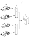
도 1은 본 발명의 일 실시예에 따른 전기 자동차의 충전 시스템의 개념도이다.1 is a conceptual diagram of a charging system for an electric vehicle according to an embodiment of the present invention.
도 1에 도시된 바와 같이, 본 발명의 일 실시예에 따른 전기 자동차 충전 시스템(1)은 충전 관리부(100), 외부 충전기(200) 및 전기 자동차(300)를 포함한다.1, an electric
전기 자동차(300)는 외부 충전기(200)와 연결되어 전력을 충전하거나 방전할 수 있다. 구체적으로 전기 자동차(300)는 배터리를 포함할 수 있으며, 외부 충전기로부터 전력을 공급받아 배터리를 충전할 수 있다. 또한, 반대로 배터리에 충전된 전력을 외부 충전기를 통해 방전할 수도 있다.The
전기 자동차(300)는 전력 충/방전을 위한 컨버터(미도시)를 포함할 수 있다. 또한, 전기 자동차(300)는 전력 충/방전간에 발생할 수 있는 위험 요인을 감지하고 제어하기 위한 각종 안전장치(미도시)를 포함할 수 있다.The
외부 충전기(200)는 충전 관리부(100)의 제어를 받아 전기 자동차(300)에게 전력을 공급한다. 외부 충전기(200)는 하나의 건물에 복수개 설치될 수 있다. 외부 충전기(200) 기둥 형태의 스터드형, 벽에 걸려있는 형태인 월 박스(Wall Box)형 및 휴대형 외부 충전기(codeset) 중 어느 하나일 수 있다. 또한, 외부 충전기(200)는 상술한 형태 외에 다른 형태로 존재할 수도 있다.The
외부 충전기(200)는 소켓(미도시)를 포함할 수 있다. 소켓은 그리드가 제공하는 교류(AC) 전원을 전기 자동차(300)에 제공한다. 전기 자동차(300)는 소켓(30)과 연결되어, 소켓(30)으로부터 교류 전력을 제공받는다.The
또한, 외부 충전기(200)는 전기 자동차(100)의 충전을 모니터링하고, 모니터링을 통해 획득한 충전 관련 정보를 사용자 또는 충전 관리부(100)에 제공할 수 있다. 구체적으로 외부 충전기(200)는 디스플레이부(미도시)를 포함할 수 있으며, 모니터링한 충전 관련 정보를 디스플레이부에 표시하여 사용자에게 제공할 수 있다.Also, the
실시예에서, 외부 충전기(200)는 사용자에 의해서는 전기 자동차(300) 측 과의 분리가 용이하지 않도록 케이블 등을 통해 일체로서 부착되며, 외부 온도, 외부 습도, 진동, 충격 등에 강인한 특성을 갖는다. In an embodiment, the
실시예에서, 외부 충전기(200)는 사용자에 의해서는 전기 자동차(300)와 결합될 수 있고 분리될 수 있도록 커넥터를 포함할 수 있다. 이때, 커넥터는 외부 온도, 외부 습도, 진동, 충격 등에 강인한 특성을 가질 필요가 있다.In an embodiment, the
실시예에서, 외부 충전기(200)는 사용자에 의해서는 그리드 측 과의 분리가 용이하지 않도록 일체로서 부착되며, 외부 온도, 외부 습도, 진동, 충격 등에 강인한 특성을 갖는다.In the embodiment, the
실시예에서, 외부 충전기(200)는 사용자에 의해서는 그리드 측 과 결합될 수 있고 분리될 수 있도록 커넥터를 포함할 수 있다. 이때, 커넥터는 외부 온도, 외부 습도, 진동, 충격 등에 강인한 특성을 가질 필요가 있다.In an embodiment, the
충전 관리부(100)는 외부 충전기(200) 및 그리드와 연결되어 전기 자동차(300)의 전력 충/방전을 제어한다. 구체적으로 하나의 건물에 설치된 외부 충전기(200)가 이용하는 전원 소스를 제어하여 전기 자동차(300) 전력 충/방전을 제어할 수 있다. The
도 2는 본 발명의 일 실시예에 따른 전기 자동차의 블록도이다.2 is a block diagram of an electric vehicle according to an embodiment of the present invention.
전기 자동차(300)는 배터리(310), 배터리 충전 장치(320), 전기 자동차 인렛(340), 통신부(330), 전동기(350) 및 제어부(305)을 포함한다.The
배터리(310)는 전기 자동차(300)의 운행을 위한 전력을 전동기(350)에 제공한다.The
전동기(350)는 배터리(310)로부터 전력을 공급받아 전기에너지를 운동에너지로 변환한다.The
전기 자동차 인렛(340)은 외부로부터 배터리(310)의 충전을 위한 전력을 받기 위한 커넥터이다. 전기 자동차 인렛(340)은 SAE J1772 규격을 따를 수 있다.The
배터리 충전 장치(320)는 전기 자동차 인렛(340)을 통해 제공된 전력을 이용하여 배터리(310)를 충전한다. 또는 배터리(310)로부터 전력을 공급받아 전동기(350)로 전달할 수 있다. 또는 전기자동차(300)의 제동 시, 전동기(350)로부터 공급되는 전력을 이용하여 배터리(310)를 충전할 수 있다. 이때, 배터리 충전 장치(320)는 교류를 직류로 변환하거나 직류를 교류로 변환할 수 있다. 다시 말해서 배터리 충전 장치(320)는 통합전력변환장치(323)를 포함할 수 있다.The
통신부(330)는 외부 충전기(200) 또는 충전 관리부(100)와 통신할 수 있다.The
제어부(305)는 전기 자동차(300)의 통신부(330), 배터리(310), 배터리 충전장치(320) 및 전기자동차 인렛(340)의 전반적인 동작을 제어한다. 구체적인 제어내용은 이하에서 추가적으로 설명한다.
The
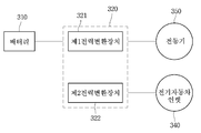
도 3은 기존의 전기자동차의 구성을 나타내는 블록도이다.3 is a block diagram showing a configuration of a conventional electric vehicle.
기존 전기자동차는 도 3에 도시된 바와 같이, 배터리(310), 전동기(350), 전기자동차 인렛(340), 제1 전력변환장치(321) 및 제2 전력변환장치(322)를 포함한다. 또한, 제1 전력변환장치(321)는 전동기(350)을 구동하기 위하여 배터리(310)의 직류에너지를 교류로 변환한다. 제2 전력변환장치(322)는 자동차의 제동 시 관성에너지에 의해 발생하는 에너지를 회수하기 위해 교류에너지를 배터리(310) 충전을 위한 직류로 변환한다. 구체적으로 자동차의 제동 시 전동기(350)가 발전기 역할을 할 수 있으며, 제2 전력변환장치(322)는 전동기(350)가 생산하는 교류에너지를 직류로 변환한다.The conventional electric vehicle includes a
또한, 전기자동차가 정차 시 충전을 위해 전기자동차 인렛(340)을 통해 전력계통과 연결될 수 있다. 이때, 제2 전력변환장치(322)가 전력계통의 교류에너지를 직류로 변환한다.Further, the electric vehicle can be connected to the electric power system through the
그러나, 기존의 전기자동차는 교류와 직류간의 상호 변환을 위해 각기 다른 전력 변환기기를 이용하였다. 구체적으로, 배터리(310)로부터 전동기(350)로 전력을 공급할 때는 제1 전력변환장치(321)를 이용하였다. 반면에, 전동기(350) 또는 전력계통으로부터 배터리로 전력을 공급할 때는 제2 전력변환장치(322)를 이용하였다.However, existing electric vehicles use different power conversion devices to convert between alternating current and direct current. Specifically, the
결과적으로 기존의 전력변환장치는 단방향 에너지 흐름만을 가지는 복수의 전력변환장치로 구성되어 생산단가가 증가하는 문제가 있었다. 또한, 동일한 기능을 수행하는 구성을 별도로 구현하여 전체 전력변환장치의 무게 및 부피가 커지는 문제가 있었다. 또한, 부품의 개수가 늘어날수록 제품의 고장율이 높아지고, 제품의 신뢰도가 떨어지는 문제가 있었다. 따라서, 이하 도 4 내지 도 7을 참고하여 기존의 문제점을 해결하는 전기자동차의 전력변환장치를 설명한다.As a result, the conventional power conversion apparatus is constituted by a plurality of power conversion apparatuses having only a unidirectional energy flow, thereby increasing the production cost. Further, there is a problem that the weight and volume of the entire power conversion apparatus are increased by separately implementing a configuration performing the same function. Further, as the number of parts increases, the failure rate of the product increases and the reliability of the product decreases. Therefore, a power conversion device of an electric vehicle that solves the conventional problems will be described with reference to FIGS. 4 to 7. FIG.
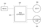
도 4는 본 발명의 일 실시 예에 따른 전기자동차를 나타내는 블록도이다. 4 is a block diagram illustrating an electric vehicle according to an embodiment of the present invention.
도 4에 도시된 바와 같이, 본 발명의 일 실시 예에 따른 배터리충전장치(320)는 독립된 복수의 구성이 아닌 하나의 통합전력변환장치(323)을 포함할 수 있다. 구체적으로 기존의 전력변환장치는 배터리 충전을 위해 교류를 직류로 변환하는 전력변환장치와, 전동기 구동을 위해 직류를 교류로 변환하는 전력변환장치가 별도로 마련되어 있었다. As shown in FIG. 4, the
그러나, 본 발명의 일 실시예에 따른 전기자동차는 단일의 통합전력변환장치(323)만을 포함한다. 구체적으로, 통합전력변환장치는 배터리(310)로부터 방전되는 직류 전력을 교류전력으로 변환하는 제1 전력변환장치 및 전기자동차 인렛(340) 또는 전동기(350)로부터 전달되는 교류 전력을 직류 전력으로 변환하는 제2 전력변환장치를 포함할 수 있다. 다시 말해서, 통합전력변환장치가 상기 제1 전력변환장치 및 제2 전력변환장치의 기능을 모두 수행할 수 있다. 통합전력변환장치(323)는 배터리(310)의 직류 전력을 교류로 변환하여 전동기(350)에 전달할 수 있다. 또한, 통합전력변환장치(323)는 전기자동차의 제동시에 관성을 이용하여 전동기로부터 전달되는 교류 전력을 직류로 변환하여 배터리(310)에 전달할 수 있다. 또한, 통합전력변환장치(323)는 정차 시에 전기자동차 인렛(340)으로 연결되는 전력 계통으로부터 교류 전력을 전달 받고, 교류 전력을 직류로 변환하여 배터리(310)에 전달할 수 있다. 구체적으로 통합전력변환장치(323)에 포함된 인버터(미도시)를 통해 교류/직류간 형태 변환을 할 수 있다.However, the electric vehicle according to an embodiment of the present invention includes only a single
결과적으로, 기존에 독립된 전력변환장치가 각각 수행하던 기능을 하나의 통합전력변환장치(323)가 할 수 있어 제작 단가의 절감 및 부피/무게의 절감 효과를 얻을 수 있다. 이하 도 5 내지 도 7을 참고하여 도 4의 통합전력변환장치(323)의 구체적인 동작을 설명한다.As a result, since the single
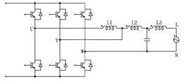
도 5는 도 4에 도시된 전기자동차 충전 시스템을 도시한 회로도이다.5 is a circuit diagram showing the electric vehicle charging system shown in FIG.
도 5에 도시된 바와 같이, 본 발명의 일 실시 예에 따른 전기 자동차 충전 시스템은 3상의 전동기 구동 시스템의 구조일 수 있다. 배터리(310)단으로부터 U상 전압, V상 전압, W상 전압이 전달될 수 있다. 배터리(310)로부터의 3상 전압을 수신한 전동기(350)는 전력 크기에 따라 전동기의 토크를 달리할 수 있다. 일 실시 예에 따른 전동기(350)는 3상 전동기로 권선 L1, L2, L3를 포함할 수 있다. 이때 L1, L2, L3는 인덕터(inductor)일 수 있다.As shown in FIG. 5, the electric vehicle charging system according to an embodiment of the present invention may be a structure of a three-phase motor drive system. The U phase voltage, the V phase voltage, and the W phase voltage may be transmitted from the
통합전력변환장치(323)는 주행 시에 전동기(350)의 권선에 전달되는 전력의 크기를 제어하여 전동기의 토크를 제어할 수 있다. 또한, 통합전력변환장치■323)는 제동 시에 관성에 의해 회전하는 전동기(350)를 발전기로 하여 전동기■350)의 권선에 유기되는 역기전력을 배터리에 저장하는 동작을 제어할 수 있다.The
또한, 전력계통의 일 단으로부터 L상 전압 및 N상 전압이 전달될 수 있다. 전기자동차 정체 시에 L상 전압 및 N상 전압으로부터 전달된 전력은 통합전력변환장치(323)을 거쳐 배터리(310)으로 전달될 수 있다. Further, an L-phase voltage and an N-phase voltage can be transmitted from one end of the power system. The electric power transmitted from the L phase voltage and the N phase voltage can be transmitted to the
본 발명의 일 실시 예에 따른 통합전력변환장치(323)는 복수의 릴레이들을 포함할 수 있다. 복수의 릴레이의 조합을 스위치 네트워크라고 할 수 있다. 릴레이는 배터리(310), 전동기(350) 및 전력계통간의 전력 흐름을 제어할 수 있다. 일 실시 예에서 릴레이의 동작에 따라 전동기(350)와 배터리(310)가 연결될 수 있다. 구체적으로, 복수의 릴레이들이 a단자와 연결될 수 있다. 복수의 릴레이들이 a단자와 연결되는 경우, 통합전력변환장치(323)는 이하에서 설명할 도 6의 회로를 포함할 수 있다. 이때, 배터리(310)가 전력을 방전하여 전동기(350)를 구동할 수 있다. The
또 다른 실시 예에서 릴레이의 동작에 따라 배터리(310)와 전력계통이 연결될 수 있다. 구체적으로, 복수의 릴레이들이 b단자와 연결될 수 있다. 복수의 릴레이들이 b단자와 연결되는 경우 통합전력변환장치(323)는 이하에서 설명할 도 7의 회로를 포함할 수 있다. 한편 릴레이는 물리적 릴레이 및 전기적 릴레이 중 적어도 어느 하나일 수 있다. 전기적 릴레이는 MOSFET일 수 있다. In another embodiment, the
다시 말해서, 통합전력변환장치(323)는 자동차의 주행 상황에 따라 릴레이를 제어하여 다양한 상황에 대처할 수 있다. 예를 들면, 자동차가 주행 중인 경우, 통합전력변환장치(323)는 릴레이를 전동기(350)와 배터리(310)를 연결하도록 제어할 수 있다. 릴레이를 통해 배터리(310)는 전력을 전동기(350)으로 전달할 수 있다. 또한, 전동기(350)의 역기전력을 배터리(310)로 전달할 수 있다.In other words, the
도 5의 실시 예에 다른 스위치 네트워크는 동기화 되어 조직되는 4개의 SPDT스위치를 포함할 수 있다. 통합전력변환장치(323)는 스위치 네트워크를 이용하여 일반적인 주행모드와 계통연계 충전모드로 변환이 가능하다. 스위치 네트워크 내부의 캐패시터(C1)는 필터를 구성할 수 있다.Other switch networks in the embodiment of FIG. 5 may include four SPDT switches organized in a synchronized manner. The
또 다른 예를 들면, 자동차가 정차 중인 경우, 통합전력변환장치(323)는 릴레이를 배터리(310)와 전력계통을 연결하도록 제어할 수 있다.As another example, when the vehicle is stopped, the
구체적으로, 통합전력변환장치(323)는 스위치 네트워크를 포함할 수 있다. 스위치 네트워크를 복수의 릴레이를 포함할 수 있다. Specifically, the
도 6 내지 도 7은 도 5에 도시된 릴레이의 동작에 따른 통합전력변환장치(323)의 회로를 나타낸다.6 to 7 show the circuit of the integrated
도 6의 회로도는 전기자동차의 주행 시 또는 제동 시의 통합전력변환장치(323)을 나타낸다. 도 6에 도시된 바와 같이, 릴레이가 배터리(310)의 일단과 전동기(350)를 연결하도록 동작할 수 있다. 이 경우, 배터리(310)로부터 전달되는 3상 전압이 전동기(350)의 권선으로 전달될 수 있다. 구체적으로 제어부(305)는 전동기(350)의 권선(L1, L2, L3)에 전달되는 전류의 크기를 인버터를 통해 제어하는 방법으로 전동기(350)의 토크를 제어할 수 있다. 또한, 전동기(350) 권선으로부터 전달되는 역기전력이 배터리(310)로 전달될 수 있다. 구체적으로 전기 자동차의 제동시 관성에 의해 회전하는 전동기(350)가 발전기로 동작할 수 있다. 제어부(305)는 전동기(350)의 권선(L1, L2, L3)에 유기되는 역기전력을 역으로 배터리에 저장하는 에너지 흐름을 인버터를 통해 제어할 수 있다. The circuit diagram of FIG. 6 shows the
도 7의 회로도는 전기자동차의 정차 시(다시 말해서 충전 시)의 통합전력변환장치(323)을 나타낸다. 정차 시에는 도 7에 도시된 회로도와 같이 결선이 변경될 수 있다. 따라서, 정차 시에는 통합전력변환장치(323)는 2병렬 운전하는 단상 인버터와 전동기의 권선(L1, L2, L3)을 이용하는 인덕터(inductor)-캐패시터(capacitor)-인덕터(intuctorL) 필터를 포함할 수 있다. 이 경우, 통합전력변환장치(323)는 전력계통에서 교류 전력을 직류로 변환하여 배터리(310)에 전달할 수 있다. 구체적으로 통합전력변환장치(323)는 전력계통으로부터의 전기 에너지를 인버터를 통해 정류하고, 정류된 전기 에너지를 배터리(310)에 저장할 수 있다.The circuit diagram of Fig. 7 shows the
본 발명의 일 실시 예에 따른 통합전력변환장치(323)는 정류동작을 통해 양방향 전력조류제어가 가능하므로 전력계통의 주파수 저하시 전력계통으로 전기에너지를 주입할 수도 있다.The
도 8은 본 발명의 일 실시 예에 따른 전기자동차의 동작을 나타내는 흐름도이다.8 is a flow chart showing the operation of an electric vehicle according to an embodiment of the present invention.
전기자동차의 제어부(305)는 전기자동차의 현재 상태를 판단한다(S101). 일 실시 예에서 전기자동차의 상태는 주행 상태, 제동 상태 및 충전 상태 중 적어도 하나일 수 있다. 제어부(305)는 전기자동차의 속도 변화를 통해 주행 상태 또는 제동 상태를 판단할 수 있다. 또한 제어부(305)는 전기자동차의 엑셀레이터 패달 또는 브레이크 패달로부터의 입력에 따라 주행 상태 또는 제동 상태를 판단할 수 있다. 또한 제어부(305)는 전기자동차 인렛(340)에 플러그가 접속되어 있는지 여부에 따라 충전 상태 여부를 판단할 수 있다. The
제어부(305)는 판단된 상태에 따라 배터리 충전 장치(320)의 동작을 제어한다(S103). 구체적으로 제어부(305)는 상태에 따라 배터리 충전 장치(320)에 포함된 통합전력변환장치(323)를 제어할 수 있다. 통합전력변환장치(323)는 복수의 릴레이를 포함할 수 있다. The
제1 실시 예에서 제어부(305)는 전기자동차의 상태가 주행 상태 또는 제동 상태인 경우 전동기(350)와 배터리(310)을 연결하도록 릴레이를 제어할 수 있다. 이 경우, 릴레이가 배터리(310)의 일 단과 전동기(350)의 일 단을 연결할 수 있다. In the first embodiment, the
제2 실시 예에서 제어부(305)는 전기자동차의 상태가 충전 상태인 경우 배터리(310)와 전기자동차 인렛(340)을 연결하도록 릴레이를 제어할 수 있다. 전기자동차 인렛(340)는 전력계통과 전기자동차를 연결할 수 있다. 이 경우, 릴레이가 배터리(310)의 일 단과 전기자동차 인렛(340)의 일 단을 연결할 수 있다.In the second embodiment, the
릴레이에 대한 제어가 완료되면, 배터리충전장치(320)는 전력을 변환한다(S105). 구체적으로 배터리충전장치(320)에 포함된 통합전력변환장치(323)을 통해 전력을 변환한다. When the control for the relay is completed, the
제1 실시 예의 경우, 통합전력변환장치(323)는 배터리(310)의 직류 전력을 교류로 변환하여 전동기(350)에 전달한다. 또한, 통합전력변환장치(323)는 전동기(350)로부터의 교류 전력을 직류로 변환하여 배터리(310)에 전달한다. In the case of the first embodiment, the
제2 실시 예의 경우, 통합전력변환장치(323)는 전력 계통으로부터의 교류 전력을 직류로 변환하여 전동기(350)에 전달한다. 이때, 전력 계통으로부터의 교류 전력은 전기자동차 인렛(340)을 통해 전달될 수 있다.
In the case of the second embodiment, the
본 발명의 일 실시 예에 의하면, 전술한 방법은, 프로그램이 기록된 매체에 프로세서가 읽을 수 있는 코드로서 구현하는 것이 가능하다. 프로세서가 읽을 수 있는 매체의 예로는, ROM, RAM, CD-ROM, 자기 테이프, 플로피 디스크, 광 데이터 저장장치 등이 있으며, 캐리어 웨이브(예를 들어, 인터넷을 통한 전송)의 형태로 구현되는 것도 포함한다.According to an embodiment of the present invention, the above-described method can be implemented as a code readable by a processor on a medium on which a program is recorded. Examples of the medium that can be read by the processor include ROM, RAM, CD-ROM, magnetic tape, floppy disk, optical data storage, etc., and may be implemented in the form of a carrier wave (e.g., transmission over the Internet) .
상기와 같이 설명된 충전기는 설명된 실시 예들의 구성과 방법이 한정되게 적용될 수 있는 것이 아니라, 실시 예들은 다양한 변형이 이루어질 수 있도록 각 실시 예들의 전부 또는 일부가 선택적으로 조합되어 구성될 수도 있다.The charger described above is not limited in the configuration and the method of the illustrated embodiments, but the embodiments may be constructed by selectively combining all or a part of the embodiments so that various modifications can be made.
Claims (8)
전기 에너지를 저장하는 배터리;
전력 계통과 배터리를 연결하는 전기자동차 인렛;
상기 배터리를 상기 전동기 및 전기자동차 인렛 중 어느 하나와 선택적으로연결하기 위한 릴레이를 포함하고, 상기 배터리로부터 방전되는 직류 전력을 교류전력으로 변환하는 제1 전력변환장치 및 상기 전기자동차 인렛 또는 전동기로부터 전달되는 교류 전력을 직류 전력으로 변환하는 제2 변환장치를 포함하는 통합전력변환장치; 및
전기자동차의 상태를 판단하고, 판단 결과에 따라 상기 전력변환장치를 제어하는 제어부를 포함하는
배터리 충방전 제어장치.An electric vehicle including an electric motor driven by electric energy,
Batteries for storing electrical energy;
Electric vehicle inlet to connect power system and battery;
And a relay for selectively connecting the battery to either the motor or the electric vehicle inlet, a first power conversion device for converting DC power discharged from the battery into AC power and a second power conversion device for transferring electric power from the electric vehicle inlet or electric motor An integrated power conversion device including a second conversion device for converting AC power into DC power; And
And a control unit for determining the state of the electric vehicle and controlling the electric power conversion apparatus according to a result of the determination
Battery charge / discharge control device.
상기 전기자동차의 상태는 주행 상태, 제동 상태 및 충전 상태 중 적어도 하나인
배터리 충방전 제어장치. The method according to claim 1,
Wherein the state of the electric vehicle is at least one of a running state, a braking state,
Battery charge / discharge control device.
상기 통합전력변환장치는 필터구성을 위한 캐패시터를 더 포함하는
배터리 충방전 제어장치.The method according to claim 1,
The integrated power inverter further comprises a capacitor for filter configuration
Battery charge / discharge control device.
상기 제어부는
현재 전기자동차의 상태가 주행 상태 또는 제동 상태로 판단된 경우, 상기 배터리와 전동기를 연결하도록 상기 릴레이를 제어하는
배터리 충방전 제어장치.The method of claim 3,
The control unit
And controls the relay to connect the battery and the motor when the current state of the electric vehicle is determined as the running state or the braking state
Battery charge / discharge control device.
상기 제어부는
전기자동차의 상태가 주행 상태인 경우, 상기 배터리로부터 전동기에 포함된 인덕터에 전달되는 전류의 크기를 제어하는
배터리 충방전 제어장치.5. The method of claim 4,
The control unit
When the state of the electric vehicle is in a running state, the controller controls the magnitude of the electric current transmitted from the battery to the inductor included in the electric motor
Battery charge / discharge control device.
상기 제어부는
전기자동차의 상태가 제동 상태인 경우, 전동기에 포함된 인덕터에 유기되는 역기전력을 배터리에 저장하는 에너지 흐름을 제어하는
배터리 충방전 제어장치.5. The method of claim 4,
The control unit
When the state of the electric vehicle is in the braking state, an energy flow that stores the back electromotive force induced in the inductor included in the electric motor is controlled
Battery charge / discharge control device.
상기 제어부는
현재 전기자동차의 상태가 충전 상태로 판단된 경우, 상기 배터리와 전기자동차 인렛을 연결하도록 상기 릴레이를 제어하는
배터리 충방전 제어장치.The method according to claim 1,
The control unit
If the current state of the electric vehicle is determined to be in a charged state, the relay is controlled to connect the battery and the electric vehicle inlet
Battery charge / discharge control device.
현재 전기자동차의 상태가 충전 상태인 경우, 상기 통합전력변환장치는 상기 전동기에 포함된 인덕터를 이용하는 인덕터-캐패시터-인덕터 필터를 포함하는
배터리 충방전 제어장치.8. The method of claim 7,
If the current state of the electric vehicle is in a charged state, the integrated power conversion apparatus includes an inductor-capacitor-inductor filter using an inductor included in the electric motor
Battery charge / discharge control device.
Priority Applications (5)
| Application Number | Priority Date | Filing Date | Title |
|---|---|---|---|
| KR1020150108392A KR20170014665A (en) | 2015-07-30 | 2015-07-30 | Control device for chanring/discharging battery |
| EP16175322.3A EP3124312A3 (en) | 2015-07-30 | 2016-06-20 | Apparatus for controlling charging/discharging of battery |
| JP2016148177A JP2017034990A (en) | 2015-07-30 | 2016-07-28 | Battery charge/discharge control device |
| US15/224,135 US20170028859A1 (en) | 2015-07-30 | 2016-07-29 | Apparatus for controlling charging/discharging of battery |
| CN201610622658.5A CN106394277A (en) | 2015-07-30 | 2016-08-01 | Apparatus for controlling charging/discharging of battery |
Applications Claiming Priority (1)
| Application Number | Priority Date | Filing Date | Title |
|---|---|---|---|
| KR1020150108392A KR20170014665A (en) | 2015-07-30 | 2015-07-30 | Control device for chanring/discharging battery |
Publications (1)
| Publication Number | Publication Date |
|---|---|
| KR20170014665A true KR20170014665A (en) | 2017-02-08 |
Family
ID=56148234
Family Applications (1)
| Application Number | Title | Priority Date | Filing Date |
|---|---|---|---|
| KR1020150108392A KR20170014665A (en) | 2015-07-30 | 2015-07-30 | Control device for chanring/discharging battery |
Country Status (5)
| Country | Link |
|---|---|
| US (1) | US20170028859A1 (en) |
| EP (1) | EP3124312A3 (en) |
| JP (1) | JP2017034990A (en) |
| KR (1) | KR20170014665A (en) |
| CN (1) | CN106394277A (en) |
Cited By (1)
| Publication number | Priority date | Publication date | Assignee | Title |
|---|---|---|---|---|
| KR20190024051A (en) * | 2017-08-31 | 2019-03-08 | 현대모비스 주식회사 | Input filter circuit device combined single phase / three phase of on-board charger for electric vehicle |
Families Citing this family (7)
| Publication number | Priority date | Publication date | Assignee | Title |
|---|---|---|---|---|
| WO2014011706A1 (en) * | 2012-07-09 | 2014-01-16 | Inertech Ip Llc | Transformerless multi-level medium-voltage uninterruptible power supply (ups) systems and methods |
| USD799421S1 (en) * | 2016-04-15 | 2017-10-10 | Ecm Peco, Inc. | Electric vehicle charging stand |
| US10381967B2 (en) | 2017-05-17 | 2019-08-13 | Toyota Motor Engineering & Manufacturing North America, Inc. | Simplified power conversion systems for vehicles |
| KR20180136177A (en) * | 2017-06-14 | 2018-12-24 | 엘에스산전 주식회사 | An energy storage system |
| USD844059S1 (en) | 2018-05-10 | 2019-03-26 | Target Brands, Inc. | Pillar sign |
| USD841094S1 (en) * | 2018-05-31 | 2019-02-19 | Target Brands, Inc. | Pillar sign |
| CN112389230B (en) * | 2019-08-15 | 2022-11-11 | 比亚迪股份有限公司 | Energy conversion device and vehicle |
Family Cites Families (13)
| Publication number | Priority date | Publication date | Assignee | Title |
|---|---|---|---|---|
| JPH0630505A (en) * | 1992-01-31 | 1994-02-04 | Fuji Electric Co Ltd | Electric system for electric automobile |
| JP5233229B2 (en) * | 2007-10-02 | 2013-07-10 | ダイキン工業株式会社 | Power system |
| EP2332246A1 (en) * | 2008-09-11 | 2011-06-15 | Eetrex Incorporated | Bi-directional inverter-charger |
| US8653788B2 (en) * | 2009-06-24 | 2014-02-18 | Toyota Jidosha Kabushiki Kaisha | Charging cable and charging system for electrically powered vehicle |
| WO2011032287A1 (en) * | 2009-09-18 | 2011-03-24 | Queen's University At Kingston | Distributed power generation interface |
| CN102844961B (en) * | 2009-11-17 | 2016-04-13 | 航空环境公司 | Integrated engine drives and batter-charghing system |
| JP2012039827A (en) * | 2010-08-11 | 2012-02-23 | Meidensha Corp | Resonance suppression controller of power converter |
| US8698354B2 (en) * | 2010-11-05 | 2014-04-15 | Schneider Electric It Corporation | System and method for bidirectional DC-AC power conversion |
| JP5794525B2 (en) * | 2011-07-22 | 2015-10-14 | 東洋電産株式会社 | Battery charger for electric vehicles and rescue vehicle |
| US9024476B2 (en) * | 2011-07-28 | 2015-05-05 | Schneider Electric It Corporation | Single-battery power topologies for online UPS systems |
| EP2768113A4 (en) * | 2011-10-14 | 2015-03-04 | Toyota Motor Co Ltd | Electric vehicle charging device |
| JP6192921B2 (en) * | 2012-11-08 | 2017-09-06 | Ntn株式会社 | Low-temperature drive control device for motor-equipped automobiles |
| US9389263B2 (en) * | 2014-06-05 | 2016-07-12 | Rockwell Automation Technologies, Inc. | Filter capacitor degradation identification using measured and expected voltage |
-
2015
- 2015-07-30 KR KR1020150108392A patent/KR20170014665A/en unknown
-
2016
- 2016-06-20 EP EP16175322.3A patent/EP3124312A3/en not_active Withdrawn
- 2016-07-28 JP JP2016148177A patent/JP2017034990A/en active Pending
- 2016-07-29 US US15/224,135 patent/US20170028859A1/en not_active Abandoned
- 2016-08-01 CN CN201610622658.5A patent/CN106394277A/en not_active Withdrawn
Cited By (1)
| Publication number | Priority date | Publication date | Assignee | Title |
|---|---|---|---|---|
| KR20190024051A (en) * | 2017-08-31 | 2019-03-08 | 현대모비스 주식회사 | Input filter circuit device combined single phase / three phase of on-board charger for electric vehicle |
Also Published As
| Publication number | Publication date |
|---|---|
| EP3124312A3 (en) | 2017-03-01 |
| JP2017034990A (en) | 2017-02-09 |
| CN106394277A (en) | 2017-02-15 |
| US20170028859A1 (en) | 2017-02-02 |
| EP3124312A2 (en) | 2017-02-01 |
Similar Documents
| Publication | Publication Date | Title |
|---|---|---|
| KR20170014665A (en) | Control device for chanring/discharging battery | |
| US10763690B2 (en) | Vehicle-side charging circuit for a vehicle with electric drive, and method for operating a vehicle-side current converter, and use of at least one winding of a vehicle-side electric machine for intermediate storagectrical machine for buffer | |
| CN102684248B (en) | Charging device between vehicle | |
| US8963482B2 (en) | Power supply apparatus for electrically powered vehicle and method for controlling the same | |
| US9172252B2 (en) | Power supply apparatus for electrically powered vehicle and method for controlling the same | |
| US9931939B2 (en) | Electrical apparatus and method for charging a battery | |
| CN103339005B (en) | Hybrid vehicle | |
| EP2919370B1 (en) | Power source device | |
| US8810061B2 (en) | Vehicular power supply apparatus, vehicle including the same, and method for controlling vehicle-mounted charger | |
| US20130106365A1 (en) | Electric motored vehicle and method for controlling electrically charging the same | |
| CN103221246A (en) | Vehicle charging device | |
| US20140225441A1 (en) | Power supply system and vehicle | |
| JP5679054B2 (en) | Power supply equipment for vehicles | |
| KR20120106457A (en) | Inverter-charger conversed device for electric vehicles and method for controlling thereof | |
| CN103875148A (en) | Vehicle charging system and method for charging vehicle | |
| CN101803143A (en) | Vehicle charger and method for charging vehicle | |
| WO2013132604A1 (en) | Electric-powered vehicle and method for controlling same | |
| RU2749439C1 (en) | Power supply device of rail vehicles | |
| KR20140057298A (en) | Converter circuit and method for transferring electrical energy | |
| WO2011159241A1 (en) | Electrical apparatus comprising drive system and electrical machine with reconnectable stator winding | |
| CN103180162A (en) | Power supply device, vehicle provided with same, and power supply method | |
| WO2011055230A2 (en) | Electric drive and battery-charging power electronic system | |
| JP2019126116A (en) | Motor drive device having power storage part, and motor drive system | |
| CN113195288A (en) | Power transmission system for vehicle | |
| JP6305364B2 (en) | Rotating electrical machine system |