Hereinafter, embodiments of the present invention will be described in detail with reference to the accompanying drawings, wherein like reference numerals are used to designate identical or similar elements, and redundant description thereof will be omitted. The suffix "module" and " part "for the components used in the following description are given or mixed in consideration of ease of specification, and do not have their own meaning or role. In the following description of the embodiments of the present invention, a detailed description of related arts will be omitted when it is determined that the gist of the embodiments disclosed herein may be blurred. It is to be understood that both the foregoing general description and the following detailed description are exemplary and explanatory and are intended to provide further explanation of the invention as claimed. , ≪ / RTI > equivalents, and alternatives.
The mobile terminal described in this specification includes a mobile phone, a smart phone, a laptop computer, a digital broadcasting terminal, a personal digital assistant (PDA), a portable multimedia player (PMP), a navigation device, a slate PC A tablet PC, an ultrabook, a wearable device such as a smartwatch, a smart glass, and a head mounted display (HMD). have.
However, it will be appreciated by those skilled in the art that the configuration according to the embodiments described herein may be applied to fixed terminals such as a digital TV, a desktop computer, a digital signage, and the like, will be.
1A is a block diagram illustrating a mobile terminal according to the present invention.
The mobile terminal 100 includes a wireless communication unit 110, an input unit 120, a sensing unit 140, an output unit 150, an interface unit 160, a memory 170, a control unit 180, and a power supply unit 190 ), And the like. The components shown in FIG. 1A are not essential for implementing a mobile terminal, so that the mobile terminal described herein may have more or fewer components than the components listed above.
The input unit 120 includes a camera 121 or an image input unit for inputting a video signal, a microphone 122 for inputting an audio signal, an audio input unit, a user input unit 123 for receiving information from a user A touch key, a mechanical key, and the like). The voice data or image data collected by the input unit 120 may be analyzed and processed by a user's control command.
The sensing unit 140 may include at least one sensor for sensing at least one of information in the mobile terminal, surrounding environment information surrounding the mobile terminal, and user information. For example, the sensing unit 140 may include a proximity sensor 141, an illumination sensor 142, a touch sensor, an acceleration sensor, a magnetic sensor, A G-sensor, a gyroscope sensor, a motion sensor, an RGB sensor, an infrared sensor, a finger scan sensor, an ultrasonic sensor, A microphone 226, a battery gauge, an environmental sensor (for example, a barometer, a hygrometer, a thermometer, a radiation detection sensor, A thermal sensor, a gas sensor, etc.), a chemical sensor (e.g., an electronic nose, a healthcare sensor, a biometric sensor, etc.). Meanwhile, the mobile terminal disclosed in the present specification can combine and utilize information sensed by at least two of the sensors.
The output unit 150 includes at least one of a display unit 151, an acoustic output unit 152, a haptic tip module 153, and a light output unit 154 to generate an output related to visual, auditory, can do. The display unit 151 may have a mutual layer structure with the touch sensor or may be integrally formed to realize a touch screen. The touch screen may function as a user input unit 123 that provides an input interface between the mobile terminal 100 and a user and may provide an output interface between the mobile terminal 100 and a user.
The interface unit 160 serves as a path to various types of external devices connected to the mobile terminal 100. The interface unit 160 is connected to a device having a wired / wireless headset port, an external charger port, a wired / wireless data port, a memory card port, And may include at least one of a port, an audio I / O port, a video I / O port, and an earphone port. In the mobile terminal 100, corresponding to the connection of the external device to the interface unit 160, it is possible to perform appropriate control related to the connected external device.
In addition, the memory 170 stores data supporting various functions of the mobile terminal 100. The memory 170 may store a plurality of application programs or applications running on the mobile terminal 100, data for operation of the mobile terminal 100, and commands. At least some of these applications may be downloaded from an external server via wireless communication. Also, at least a part of these application programs may exist on the mobile terminal 100 from the time of shipment for the basic functions (e.g., telephone call receiving function, message receiving function, and calling function) of the mobile terminal 100. Meanwhile, the application program may be stored in the memory 170, installed on the mobile terminal 100, and may be operated by the control unit 180 to perform the operation (or function) of the mobile terminal.
In addition to the operations related to the application program, the control unit 180 typically controls the overall operation of the mobile terminal 100. The control unit 180 may process or process signals, data, information, and the like input or output through the above-mentioned components, or may drive an application program stored in the memory 170 to provide or process appropriate information or functions to the user.
In addition, the controller 180 may control at least some of the components illustrated in FIG. 1A in order to drive an application program stored in the memory 170. FIG. In addition, the controller 180 may operate at least two of the components included in the mobile terminal 100 in combination with each other for driving the application program.
The power supply unit 190 receives external power and internal power under the control of the controller 180 and supplies power to the components included in the mobile terminal 100. The power supply unit 190 includes a battery, which may be an internal battery or a replaceable battery.
At least some of the components may operate in cooperation with one another to implement a method of operation, control, or control of a mobile terminal according to various embodiments described below. In addition, the operation, control, or control method of the mobile terminal may be implemented on the mobile terminal by driving at least one application program stored in the memory 170. [
Next, the input unit 120 is for inputting image information (or signal), audio information (or signal), data, or information input from a user. For inputting image information, Or a plurality of cameras 121 may be provided. The camera 121 processes image frames such as still images or moving images obtained by the image sensor in the video communication mode or the photographing mode. The processed image frame may be displayed on the display unit 151 or stored in the memory 170. [ A plurality of cameras 121 provided in the mobile terminal 100 may be arranged to have a matrix structure and various angles or foci may be provided to the mobile terminal 100 through the camera 121 having the matrix structure A plurality of pieces of image information can be input. In addition, the plurality of cameras 121 may be arranged in a stereo structure to acquire a left image and a right image for realizing a stereoscopic image.
The microphone 122 processes the external acoustic signal into electrical voice data. The processed voice data can be utilized variously according to a function (or a running application program) being executed in the mobile terminal 100. Meanwhile, the microphone 122 may be implemented with various noise reduction algorithms for eliminating noise generated in receiving an external sound signal.
The user input unit 123 is for receiving information from a user and when the information is inputted through the user input unit 123, the control unit 180 can control the operation of the mobile terminal 100 to correspond to the input information . The user input unit 123 may include a mechanical input means (or a mechanical key such as a button located on the front, rear or side of the mobile terminal 100, a dome switch, a jog wheel, Jog switches, etc.) and touch-type input means. For example, the touch-type input means may comprise a virtual key, a soft key or a visual key displayed on the touch screen through software processing, And a touch key disposed on the touch panel. Meanwhile, the virtual key or the visual key can be displayed on a touch screen having various forms, for example, a graphic, a text, an icon, a video, As shown in FIG.
Meanwhile, the sensing unit 140 senses at least one of information in the mobile terminal, surrounding environment information surrounding the mobile terminal, and user information, and generates a corresponding sensing signal. The control unit 180 may control the driving or operation of the mobile terminal 100 or may perform data processing, function or operation related to the application program installed in the mobile terminal 100 based on the sensing signal. Representative sensors among various sensors that may be included in the sensing unit 140 will be described in more detail.
First, the proximity sensor 141 refers to a sensor that detects the presence of an object approaching a predetermined detection surface, or the presence of an object in the vicinity of the detection surface, without mechanical contact by using electromagnetic force or infrared rays. The proximity sensor 141 may be disposed in the inner area of the mobile terminal or in proximity to the touch screen, which is covered by the touch screen.
Examples of the proximity sensor 141 include a transmission type photoelectric sensor, a direct reflection type photoelectric sensor, a mirror reflection type photoelectric sensor, a high frequency oscillation type proximity sensor, a capacitive proximity sensor, a magnetic proximity sensor, and an infrared proximity sensor. In the case where the touch screen is electrostatic, the proximity sensor 141 can be configured to detect the proximity of the object with a change of the electric field along the proximity of the object having conductivity. In this case, the touch screen (or touch sensor) itself may be classified as a proximity sensor.
On the other hand, for convenience of explanation, the act of recognizing that the object is located on the touch screen in proximity with no object touching the touch screen is referred to as "proximity touch & The act of actually touching an object on the screen is called a "contact touch. &Quot; The position at which the object is closely touched on the touch screen means a position where the object corresponds to the touch screen vertically when the object is touched. The proximity sensor 141 can detect a proximity touch and a proximity touch pattern (e.g., a proximity touch distance, a proximity touch direction, a proximity touch speed, a proximity touch time, a proximity touch position, have. Meanwhile, the control unit 180 processes data (or information) corresponding to the proximity touch operation and the proximity touch pattern sensed through the proximity sensor 141 as described above, and further provides visual information corresponding to the processed data It can be output on the touch screen. Furthermore, the control unit 180 can control the mobile terminal 100 such that different operations or data (or information) are processed according to whether the touch to the same point on the touch screen is a proximity touch or a touch touch .
The touch sensor uses a touch (or touch input) applied to the touch screen (or the display unit 151) by using at least one of various touch methods such as a resistance film type, a capacitive type, an infrared type, an ultrasonic type, Detection.
For example, the touch sensor may be configured to convert a change in a pressure applied to a specific portion of the touch screen or a capacitance generated in a specific portion to an electrical input signal. The touch sensor may be configured to detect a position, an area, a pressure at the time of touch, a capacitance at the time of touch, and the like where a touch object touching the touch screen is touched on the touch sensor. Here, the touch object may be a finger, a touch pen, a stylus pen, a pointer, or the like as an object to which a touch is applied to the touch sensor.
Thus, when there is a touch input to the touch sensor, the corresponding signal (s) is sent to the touch controller. The touch controller processes the signal (s) and transmits the corresponding data to the controller 180. Thus, the control unit 180 can know which area of the display unit 151 is touched or the like. Here, the touch controller may be a separate component from the control unit 180, and may be the control unit 180 itself.
On the other hand, the control unit 180 may perform different controls or perform the same control according to the type of the touch object touching the touch screen (or a touch key provided on the touch screen). Whether to perform different controls or to perform the same control according to the type of the touch object may be determined according to the current state of the mobile terminal 100 or an application program being executed.
On the other hand, the touch sensors and the proximity sensors discussed above can be used independently or in combination to provide a short touch (touch), a long touch, a multi touch, a drag touch ), Flick touch, pinch-in touch, pinch-out touch, swipe touch, hovering touch, and the like. Touch can be sensed.
The ultrasonic sensor can recognize the position information of the object to be sensed by using ultrasonic waves. Meanwhile, the controller 180 can calculate the position of the wave generating source through the information sensed by the optical sensor and the plurality of ultrasonic sensors. The position of the wave source can be calculated using the fact that the light is much faster than the ultrasonic wave, that is, the time when the light reaches the optical sensor is much faster than the time the ultrasonic wave reaches the ultrasonic sensor. More specifically, the position of the wave generating source can be calculated using the time difference with the time when the ultrasonic wave reaches the reference signal.
The camera 121 includes at least one of a camera sensor (for example, a CCD, a CMOS, etc.), a photo sensor (or an image sensor), and a laser sensor.
The camera 121 and the laser sensor may be combined with each other to sense a touch of the sensing object with respect to the three-dimensional stereoscopic image. The photosensor can be laminated to the display element, which is adapted to scan the movement of the object to be detected proximate to the touch screen. More specifically, the photosensor mounts photo diodes and TRs (Transistors) in a row / column and scans the contents loaded on the photosensor using an electrical signal that varies according to the amount of light applied to the photo diode. That is, the photo sensor performs coordinate calculation of the object to be sensed according to the amount of change of light, and position information of the object to be sensed can be obtained through the calculation.
The display unit 151 displays (outputs) information processed by the mobile terminal 100. For example, the display unit 151 may display execution screen information of an application program driven by the mobile terminal 100 or UI (User Interface) and GUI (Graphic User Interface) information according to the execution screen information .
Also, the display unit 151 may be configured as a stereoscopic display unit for displaying a stereoscopic image.
In the stereoscopic display unit, a three-dimensional display system such as a stereoscopic system (glasses system), an autostereoscopic system (no-glasses system), and a projection system (holographic system) can be applied.
The sound output unit 152 may output audio data received from the wireless communication unit 110 or stored in the memory 170 in a call signal reception mode, a call mode or a recording mode, a voice recognition mode, a broadcast reception mode, The sound output unit 152 also outputs sound signals related to functions (e.g., call signal reception sound, message reception sound, etc.) performed in the mobile terminal 100. [ The audio output unit 152 may include a receiver, a speaker, a buzzer, and the like.
The haptic module 153 generates various tactile effects that the user can feel. A typical example of the haptic effect generated by the haptic module 153 may be vibration. The intensity and pattern of the vibration generated in the haptic module 153 can be controlled by the user's selection or the setting of the control unit. For example, the haptic module 153 may synthesize and output different vibrations or sequentially output the vibrations.
In addition to vibration, the haptic module 153 may be configured to perform various functions such as a pin arrangement vertically moving with respect to the contact skin surface, a spraying force or suction force of the air through the injection port or the suction port, a touch on the skin surface, And various tactile effects such as an effect of reproducing a cold sensation using an endothermic or exothermic element can be generated.
The haptic module 153 can transmit the tactile effect through the direct contact, and the tactile effect can be felt by the user through the muscles of the finger or arm. The haptic module 153 may include two or more haptic modules 153 according to the configuration of the mobile terminal 100.
The light output unit 154 outputs a signal for notifying the occurrence of an event using the light of the light source of the mobile terminal 100. Examples of events that occur in the mobile terminal 100 may include message reception, call signal reception, missed call, alarm, schedule notification, email reception, information reception through an application, and the like.
The signal output from the light output unit 154 is implemented as the mobile terminal emits light of a single color or a plurality of colors to the front or rear surface. The signal output may be terminated by the mobile terminal detecting the event confirmation of the user.
The interface unit 160 serves as a path for communication with all external devices connected to the mobile terminal 100. The interface unit 160 receives data from an external device or supplies power to each component in the mobile terminal 100 or transmits data in the mobile terminal 100 to an external device. For example, a port for connecting a device equipped with a wired / wireless headset port, an external charger port, a wired / wireless data port, a memory card port, an audio I / O port, a video I / O port, an earphone port, and the like may be included in the interface unit 160.
The identification module is a chip for storing various information for authenticating the use right of the mobile terminal 100 and includes a user identification module (UIM), a subscriber identity module (SIM) A universal subscriber identity module (USIM), and the like. Devices with identification modules (hereinafter referred to as "identification devices") can be manufactured in a smart card format. Accordingly, the identification device can be connected to the terminal 100 through the interface unit 160. [
The interface unit 160 may be a path through which power from the cradle is supplied to the mobile terminal 100 when the mobile terminal 100 is connected to an external cradle, And various command signals may be transmitted to the mobile terminal 100. The various command signals or the power source input from the cradle may be operated as a signal for recognizing that the mobile terminal 100 is correctly mounted on the cradle.
Meanwhile, as described above, the control unit 180 controls the operations related to the application program and the general operation of the mobile terminal 100. [ For example, when the state of the mobile terminal meets a set condition, the control unit 180 can execute or release a lock state for restricting input of a user's control command to applications.
In addition, the control unit 180 performs control and processing related to voice communication, data communication, video call, or the like, or performs pattern recognition processing to recognize handwriting input or drawing input performed on the touch screen as characters and images, respectively . Further, the controller 180 may control any one or a plurality of the above-described components in order to implement various embodiments described below on the mobile terminal 100 according to the present invention.
The power supply unit 190 receives external power and internal power under the control of the controller 180 and supplies power necessary for operation of the respective components. The power supply unit 190 includes a battery, the battery may be an internal battery configured to be chargeable, and may be detachably coupled to the terminal body for charging or the like.
In addition, the power supply unit 190 may include a connection port, and the connection port may be configured as an example of an interface 160 through which an external charger for supplying power for charging the battery is electrically connected.
As another example, the power supply unit 190 may be configured to charge the battery in a wireless manner without using the connection port. In this case, the power supply unit 190 may use at least one of an inductive coupling method based on a magnetic induction phenomenon from an external wireless power transmission apparatus and a magnetic resonance coupling method based on an electromagnetic resonance phenomenon Power can be delivered.
In the following, various embodiments may be embodied in a recording medium readable by a computer or similar device using, for example, software, hardware, or a combination thereof.
1B and 1C are a front perspective view and a rear perspective view of the mobile terminal 100 related to the present invention.
Referring to FIGS. 1B and 1C, the disclosed mobile terminal 100 includes a bar-shaped terminal body. However, the present invention is not limited thereto and can be applied to various structures such as a folder type, a flip type, a slide type, a swing type, and a swivel type in which a watch type, a clip type, a glass type or two or more bodies are relatively movably coupled . A description of a particular type of mobile terminal, although relevant to a particular type of mobile terminal, is generally applicable to other types of mobile terminals.
Here, the terminal body can be understood as a concept of referring to the mobile terminal 100 as at least one aggregate.
The mobile terminal 100 includes a case (for example, a frame, a housing, a cover, and the like) that forms an appearance. As shown, the mobile terminal 100 may include a front case 101 and a rear case 102. Various electronic components are disposed in the inner space formed by the combination of the front case 101 and the rear case 102. At least one middle case may be additionally disposed between the front case 101 and the rear case 102.
A display unit 151 is disposed on a front surface of the terminal body to output information. The window 151a of the display unit 151 may be mounted on the front case 101 to form a front surface of the terminal body together with the front case 101. [
In some cases, electronic components may also be mounted on the rear case 102. Electronic parts that can be mounted on the rear case 102 include detachable batteries, an identification module, a memory card, and the like. In this case, a rear cover 103 for covering the mounted electronic components can be detachably coupled to the rear case 102. Therefore, when the rear cover 103 is separated from the rear case 102, the electronic parts mounted on the rear case 102 are exposed to the outside.
As shown, when the rear cover 103 is coupled to the rear case 102, a side portion of the rear case 102 can be exposed. In some cases, the rear case 102 may be completely covered by the rear cover 103 during the engagement. Meanwhile, the rear cover 103 may be provided with an opening for exposing the camera 121b and the sound output unit 152b to the outside.
These cases 101, 102, and 103 may be formed by injection molding of synthetic resin or may be formed of metal such as stainless steel (STS), aluminum (Al), titanium (Ti), or the like.
The mobile terminal 100 may be configured such that one case provides the internal space, unlike the above example in which a plurality of cases provide an internal space for accommodating various electronic components. In this case, a unibody mobile terminal 100 in which synthetic resin or metal is connected from the side to the rear side can be realized.
Meanwhile, the mobile terminal 100 may include a waterproof unit (not shown) for preventing water from penetrating into the terminal body. For example, the waterproof portion is provided between the window 151a and the front case 101, between the front case 101 and the rear case 102, or between the rear case 102 and the rear cover 103, And a waterproof member for sealing the inside space of the oven.
The mobile terminal 100 is provided with a display unit 151, first and second sound output units 152a and 152b, a proximity sensor 141, an illuminance sensor 142, a light output unit 154, Cameras 121a and 121b, first and second operation units 123a and 123b, a microphone 122, an interface unit 160, and the like.
1B and 1C, a display unit 151, a first sound output unit 152a, a proximity sensor 141, an illuminance sensor 142, an optical output unit (not shown) A second operation unit 123b, a microphone 122 and an interface unit 160 are disposed on a side surface of the terminal body, And a mobile terminal 100 having a second sound output unit 152b and a second camera 121b disposed on a rear surface thereof.
However, these configurations are not limited to this arrangement. These configurations may be excluded or replaced as needed, or placed on different planes. For example, the first operation unit 123a may not be provided on the front surface of the terminal body, and the second sound output unit 152b may be provided on the side surface of the terminal body rather than the rear surface of the terminal body.
The display unit 151 displays (outputs) information processed by the mobile terminal 100. For example, the display unit 151 may display execution screen information of an application program driven by the mobile terminal 100 or UI (User Interface) and GUI (Graphic User Interface) information according to the execution screen information .
The display unit 151 may be a liquid crystal display (LCD), a thin film transistor-liquid crystal display (TFT LCD), an organic light-emitting diode (OLED), a flexible display display, a 3D display, and an e-ink display.
In addition, the display unit 151 may exist in two or more depending on the embodiment of the mobile terminal 100. In this case, the mobile terminal 100 may be provided with a plurality of display portions spaced apart from each other or disposed integrally with one another, or may be disposed on different surfaces, respectively.
The display unit 151 may include a touch sensor that senses a touch with respect to the display unit 151 so that a control command can be received by a touch method. When a touch is made to the display unit 151, the touch sensor senses the touch, and the control unit 180 generates a control command corresponding to the touch based on the touch. The content input by the touch method may be a letter or a number, an instruction in various modes, a menu item which can be designated, and the like.
The touch sensor may be a film having a touch pattern and disposed between the window 151a and a display (not shown) on the rear surface of the window 151a, or may be a metal wire . Alternatively, the touch sensor may be formed integrally with the display. For example, the touch sensor may be disposed on a substrate of the display or inside the display.
In this way, the display unit 151 can form a touch screen together with the touch sensor. In this case, the touch screen can function as a user input unit 123 (see FIG. 1A). In some cases, the touch screen may replace at least some functions of the first operation unit 123a.
The first sound output unit 152a may be implemented as a receiver for transmitting a call sound to a user's ear and the second sound output unit 152b may be implemented as a loud speaker for outputting various alarm sounds or multimedia playback sounds. ). ≪ / RTI >
The window 151a of the display unit 151 may be provided with an acoustic hole for emitting the sound generated from the first acoustic output unit 152a. However, the present invention is not limited to this, and the sound may be configured to be emitted along an assembly gap (for example, a gap between the window 151a and the front case 101) between the structures. In this case, the appearance of the mobile terminal 100 can be made more simple because the hole formed independently for the apparent acoustic output is hidden or hidden.
The optical output unit 154 is configured to output light for notifying the occurrence of an event. Examples of the event include a message reception, a call signal reception, a missed call, an alarm, a schedule notification, an email reception, and reception of information through an application. The control unit 180 may control the light output unit 154 to terminate the light output when the event confirmation of the user is detected.
The first camera 121a processes an image frame of a still image or a moving image obtained by the image sensor in the photographing mode or the video communication mode. The processed image frame can be displayed on the display unit 151 and can be stored in the memory 170. [
The first and second operation units 123a and 123b may be collectively referred to as a manipulating portion as an example of a user input unit 123 operated to receive a command for controlling the operation of the mobile terminal 100 have. The first and second operation units 123a and 123b can be employed in any manner as long as the user is in a tactile manner such as touch, push, scroll, or the like. In addition, the first and second operation units 123a and 123b may be employed in a manner that the user operates the apparatus without touching the user through a proximity touch, a hovering touch, or the like.
In this figure, the first operation unit 123a is a touch key, but the present invention is not limited thereto. For example, the first operation unit 123a may be a mechanical key or a combination of a touch key and a touch key.
The contents input by the first and second operation units 123a and 123b can be variously set. For example, the first operation unit 123a receives a command such as a menu, a home key, a cancellation, a search, and the like, and the second operation unit 123b receives a command from the first or second sound output unit 152a or 152b The size of the sound, and the change of the display unit 151 to the touch recognition mode.
On the other hand, a rear input unit (not shown) may be provided on the rear surface of the terminal body as another example of the user input unit 123. The rear input unit is operated to receive a command for controlling the operation of the mobile terminal 100, and input contents may be variously set. For example, commands such as power on / off, start, end, scrolling, and the like, the size adjustment of the sound output from the first and second sound output units 152a and 152b, And the like can be inputted. The rear input unit may be implemented as a touch input, a push input, or a combination thereof.
The rear input unit may be disposed so as to overlap with the front display unit 151 in the thickness direction of the terminal body. For example, the rear input unit may be disposed at the rear upper end of the terminal body such that when the user holds the terminal body with one hand, the rear input unit can be easily operated using the index finger. However, the present invention is not limited thereto, and the position of the rear input unit may be changed.
When a rear input unit is provided on the rear surface of the terminal body, a new type of user interface using the rear input unit can be realized. When the first operation unit 123a is not disposed on the front surface of the terminal body in place of at least a part of the functions of the first operation unit 123a provided on the front surface of the terminal body, The display unit 151 may be configured as a larger screen.
Meanwhile, the mobile terminal 100 may be provided with a fingerprint recognition sensor for recognizing the fingerprint of the user, and the controller 180 may use the fingerprint information sensed through the fingerprint recognition sensor as authentication means. The fingerprint recognition sensor may be embedded in the display unit 151 or the user input unit 123.
The microphone 122 is configured to receive the user's voice, other sounds, and the like. The microphone 122 may be provided at a plurality of locations to receive stereophonic sound.
The interface unit 160 is a path through which the mobile terminal 100 can be connected to an external device. For example, the interface unit 160 may include a connection terminal for connection with another device (for example, an earphone or an external speaker), a port for short-range communication (for example, an infrared port (IrDA Port), a Bluetooth port A wireless LAN port, or the like), or a power supply terminal for supplying power to the mobile terminal 100. The interface unit 160 may be implemented as a socket for receiving an external card such as a SIM (Subscriber Identification Module) or a UIM (User Identity Module) or a memory card for storing information.
And a second camera 121b may be disposed on a rear surface of the terminal body. In this case, the second camera 121b has a photographing direction which is substantially opposite to that of the first camera 121a.
The second camera 121b may include a plurality of lenses arranged along at least one line. The plurality of lenses may be arranged in a matrix form. Such a camera can be named an 'array camera'. When the second camera 121b is configured as an array camera, images can be taken in various ways using a plurality of lenses, and a better quality image can be obtained.
The flash 124 may be disposed adjacent to the second camera 121b. The flash 124 shines light toward the subject when the subject is photographed by the second camera 121b.
And a second sound output unit 152b may be additionally disposed in the terminal body. The second sound output unit 152b may implement a stereo function together with the first sound output unit 152a and may be used for implementing a speakerphone mode in a call.
The terminal body may be provided with at least one antenna for wireless communication. The antenna may be embedded in the terminal body or formed in the case. For example, an antenna constituting a part of the broadcast receiving module 111 (see FIG. 1A) may be configured to be able to be drawn out from the terminal body. Alternatively, the antenna may be formed in a film type and attached to the inner surface of the rear cover 103, or a case including a conductive material may be configured to function as an antenna.
The terminal body is provided with a power supply unit 190 (see FIG. 1A) for supplying power to the mobile terminal 100. The power supply unit 190 may include a battery 191 built in the terminal body or detachable from the outside of the terminal body.
The battery 191 may be configured to receive power through a power cable connected to the interface unit 160. In addition, the battery 191 may be configured to be wirelessly chargeable through a wireless charger. The wireless charging may be implemented by a magnetic induction method or a resonance method (magnetic resonance method).
The rear cover 103 is configured to be coupled to the rear case 102 so as to cover the battery 191 to restrict the release of the battery 191 and to protect the battery 191 from external impact and foreign matter . When the battery 191 is detachably attached to the terminal body, the rear cover 103 may be detachably coupled to the rear case 102.
The mobile terminal 100 may be provided with an accessory that protects the appearance or supports or expands the function of the mobile terminal 100. [ One example of such an accessory is a cover or pouch that covers or accommodates at least one side of the mobile terminal 100. [ The cover or pouch may be configured to interlock with the display unit 151 to expand the function of the mobile terminal 100. Another example of an accessory is a touch pen for supplementing or extending a touch input to the touch screen.
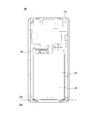
FIG. 2 shows an embodiment of a mobile terminal 100 with a rear case removed according to the present invention.
The housing 210 forming the external appearance of the mobile terminal 100 may include a front portion 250 for mounting the main board 251 therein. The opening portion 220 may be formed on one side of the housing 210 . One side of the housing 210 may mean one of four corners if the mobile terminal 100 has four corners. Accordingly, the opening 220 may be provided on one side of the side surface of the housing 210 of the mobile terminal 100.
In particular, the opening 220 may be provided at the lower end of the housing 210 so that the user can easily insert and remove the tray 230.
The opening 220 may be disposed on one side of the housing 210 as described above. The size of the opening 220 may vary depending on the role of the tray 230. For example, when the tray 230 is mounted on the battery, the battery 230 may be mounted to a size for mounting the battery. When the tray 230 serves as an additional touch input unit, the tray 230 may be smaller in size than a battery.
The tray 230 can be pulled into the full length 250 through the opening 220 or out of the housing 210. [ The tray 230 may be coupled to the front slot 250 when the tray 230 is fully drawn inward of the housing 210.
3 is a bottom perspective view of a mobile terminal 100 according to the present invention.
The outer surface of the tray 230 and the outer surface of the opening 220 may form the same plane when the tray 230 is slid inside the housing 210 to be coupled to the front portion 250 (a)). Therefore, the other surface of the tray 230 is covered by the housing 210.
The outer surface of the tray 230 and the outer surface boundary 233 of the opening portion 220 of the housing 210 may be provided with a waterproof portion for waterproofing. The waterproof portion may include an elastic material such as rubber. When the tray 230 is coupled to the housing 210, the waterproof function can be performed by the waterproof part.
The outer surface of the tray 230 may have a connection port 234 for connecting an external device. For example, the connection port 234 may be a port such as a micro USB. The connection port 234 may be connected to the additional terminal. In this case, the flexible substrate 240 has a first pattern for connecting the electronic signal connected to the extension portion 239 to the main substrate 251, and a second pattern for connecting the electronic signal of the connection port 234 to the main substrate 251, Pattern may be provided.
4 and 5 show another embodiment of the mobile terminal 100 in which the rear case related to the present invention is removed.
If necessary, the outer surface 2301 of the tray may be inserted into the housing 210 or protrude outwardly by a predetermined level difference from the outer surface 2201 of the opening.
Referring to FIG. 4, the outer surface 2301 of the tray may protrude outwardly of the housing 210 by a predetermined level difference from the outer surface 2201 of the opening. At this time, the user may further include a groove 235 at the slide end so that the user can easily grasp the tray 230. Accordingly, when the groove is provided, a coupling method of the front portion 250 and the tray 230 via the push-push module 260 as described later may be omitted.
Referring to FIG. 5, the outer surface of the tray 230 may be recessed toward the inside of the housing 210 by a predetermined level difference from the outer surface of the opening 220. In this case, it is possible to prevent the user from unintentionally touching the tray 230 to slide out. As described later, in this case, it may be effective to use the push-push module 260 method in the slide method.
Referring again to FIG. 2, the flexible substrate 240 connects the tray 230 and the main substrate 251 of the mobile terminal 100. One end of the flexible substrate 240 is connected to the contact of the tray 230 The terminal 236 may be connected to the connection terminal, and the other end may be connected to the main board 251.
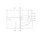
FIG. 6 is a perspective view and a combined perspective view of the flexible substrate 240 relating to the present invention.
When the tray 230 is slid, the contact terminals are also slid together, so that one end of the flexible substrate 240 coupled to the contact terminal must also be coupled and movable. Therefore, even in such a case, the flexible substrate 240 can have a three-dimensional shape instead of a planar shape so that the flexible substrate 240 can have a stable shape.
The surface on which the main substrate 251 and the other end of the flexible substrate 245 are provided may be referred to as a first plane and the surface on which the contact terminals of the tray 230 and the flexible substrate end 244 are provided may be referred to as a second plane.
The flexible substrate 240 may have a three-dimensional shape provided over the first plane and the second plane. The first region 241 of the flexible substrate 240 may be provided on the first plane and the second region 242 may be provided on the second plane. The bent portion 243 may be bent in the first region 241 and lead to the second region 242. [ The bent portion 243 may divide the first region 241 and the second region 242 while varying as the tray 230 is slid.
When the tray 230 is drawn out of the housing 210, the bent portion 243 increases the first area 241 to reduce the second area 242, and the tray 230 is drawn into the front part 250 The hour bend section 243 can reduce the first area 241 and increase the second area 242. [
The flexible substrate 240 may be biased to the left or right of the tray 230. The flexible substrate 240 may include a fixing hole for mounting the flexible substrate 240 on one side of the tray 230 when the flexible substrate 240 is biased to either the left side or the right side of the tray 230. [ The fixing hole includes a first fixing hole 237 for seating the first region 241 of the flexible substrate 240 and a second fixing hole 238 for securing the second region 242 of the flexible substrate 240, . ≪ / RTI >
When the tray 230 is slid, the first area 241 or the second area 242 of the flexible substrate 240 is inserted into the fixing hole, and the position of the bent part 243 can be stably moved without being released to the outside .
Referring to FIG. 2, when the tray 230 is coupled to the inside of the opening 220 of the housing 210, the tray 230 and the front and rear doors 230, Push module 250 may be coupled in a push-push module 260 fashion.
Figs. 7 and 8 are enlarged views of region A in Fig. 2 (a). In particular, FIG. 7 illustrates a non-constrained push-push module 260, and FIG. 8 illustrates a constrained push-push module 260.
7 (a) shows a state in which the tray 230 is fully engaged with the front part 250, and FIG. 7 (b) shows a state in which the tray 230 is separated from the front part 250.
One end 2611 of the fixed end 261 is fixed to the first member 263 of the push-push module 260 and the other end 2612 of the fixed end 261 is moved along the heart-shaped guide hole 262 do.
When the tray 230 is compressed once, the other end 2612 of the fixed end 261 is positioned at the first point 2621 of the heart-shaped guide hole 262 as shown in FIG. 7 (a) And is seated on the second point 2622 of the heart-shaped guide hole 262. In this case, since the second member 264 is most compressed toward the front portion 250, the tray 230 can be coupled to the front portion 250. When the tray 230 is further compressed, the other end 2612 of the fixed end 261 is seated on the third point 2623 of the heart-shaped guide hole 262 as shown in FIG. 7 (b) 264 are most expanded in the front portion 250, so that the tray 230 is separated from the front portion 250.
The shape of the push-push module 260 is not limited to the push-push module 260 of the unrestrained type shown in FIG. 7, and the push-push module 260 of the constrained type as shown in FIG. 8 may be used. In general, the push-push module 260 of the unconstrained type is mainly used when the reciprocating range is large, and the push-push module 260 of the constrained type is mainly used when the reciprocating range is small.
Unlike the non-constraint push-push module 260 of FIG. 7, in the constraint push-push module 260 of FIG. 8, the fixed end 261 may be provided with two links including joints. Also, the heart cam may be provided in a direction opposite to the non-restricting mode, and the rest may be provided in the same manner as the non-restricting push-push module 260.
Fig. 9 is an enlarged view of the area B in Fig. 2 (c).
As the tray 230 is slid inside the housing 210 and stably coupled by the push-push module 260, even if the tray 230 is slid and protruded by the maximum displacement, the tray 230 can be stably It needs to be fixed.
The fixed protrusions 231 may be provided symmetrically on both inner sides of the sliding sides of the tray 230. The outer side of the opening 220 of the housing 210 may include a separation preventing step 221 and a restoration preventing projection 222 having a length corresponding to the fixing projection 231. The separation preventing step portion 221 prevents the tray 230 from completely disengaging from the housing 210 and the recovery preventing protrusion 222 prevents the tray 230 from being inadvertently slid toward the inside of the housing 210 Can play a role.
When the tray 230 is pushed inward beyond a specific force, the fixing protrusion 231 moves to the inside of the restoration protrusion 222 and can freely slide inward.
The rail portion may be provided along the moving direction of the tray 230 on the side surface of the tray 230. The rail portion may slide along the slide guide portion provided inside the opening portion 220 of the housing 210.
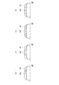
10 and 11 illustrate a mobile terminal 100 in which a tray 230 related to the present invention protrudes from a housing 210. As shown in FIG.
The tray 230 may have the functions necessary for the mobile terminal 100 as needed.
Referring to FIG. 10, the tray 230 may have a seat portion on which the replaceable battery is mounted. When replacing the replaceable battery, the tray 230 can be removed from the housing 210 to be replaced, and after the replacement, the tray 230 can be coupled to the housing 210 again. Even if the tray 230 is taken out, since the flexible board 240 is electrically connected to the main board 251, the power can still be supplied through the battery.
When the tray 230 is slid and protruded, an additional input / output unit may be provided on the extension portion 239 exposed on the front surface or the rear surface.
11 (a), the additional input / output unit may be a touch input unit, for example. In particular, when the input unit is not provided to maximize the area of the display unit, the mobile terminal 100 receives an input signal through the touch input on the display unit. Therefore, in this case, if an additional input unit is provided in the extension unit 239, the user input unit can be extended without touch input on the display unit.
11 (b), the additional input / output unit may be a secondary display. A secondary display can be useful in multitasking situations where more than one application is running. For example, if a video viewing application and a messaging application are simultaneously running, the main display unit may view an image, and if a message arrives through a messaging application, the content may be output through a secondary display unit to prevent interference with the viewing of the image .
11 (c), the additional input / output unit may include an extended sound output unit.
Referring to FIG. 11 (d), the additional input / output unit may provide an area for an external expansion slot. It may serve as an expansion slot for mounting a component, such as a woofer card, or a micro SD card, which requires replacement on the mobile terminal 100 in addition to the battery.
The additional input / output unit is not limited to the above-described embodiment, and any additional input / output unit can be mounted within a range of similar functions.
Furthermore, the expansion unit 239 is not limited to the additional input / output unit, and various functions that are possible within the limitation of the space can be added. For example, a built-in antenna or the like may be provided. If necessary, the antenna may be extended to the outside to obtain a higher radio signal transmission / reception ratio.
The opening of the housing 210 may include a proximity sensor that recognizes whether the tray 230 is coupled to the side on which the tray 230 is slidably engaged. The proximity sensor may generate a signal as to whether the tray 230 is coupled or protruded and transmit the signal to the control unit. The controller may automatically activate the function of the extension part 239 when the tray 230 is projected, thereby enhancing user convenience. On the contrary, when the tray 230 is coupled, the function of the extension part 239 is automatically deactivated, thereby minimizing unnecessary power consumption, thereby enhancing user convenience.
It will be apparent to those skilled in the art that the present invention may be embodied in other specific forms without departing from the spirit or essential characteristics thereof. The foregoing detailed description should not be construed in all aspects as limiting and should be considered illustrative. The scope of the present invention should be determined by rational interpretation of the appended claims, and all changes within the scope of equivalents of the present invention are included in the scope of the present invention.