KR20170013541A - Apparatus and Control Method for Transferring Automatic Load Switch - Google Patents
Apparatus and Control Method for Transferring Automatic Load Switch Download PDFInfo
- Publication number
- KR20170013541A KR20170013541A KR1020150106312A KR20150106312A KR20170013541A KR 20170013541 A KR20170013541 A KR 20170013541A KR 1020150106312 A KR1020150106312 A KR 1020150106312A KR 20150106312 A KR20150106312 A KR 20150106312A KR 20170013541 A KR20170013541 A KR 20170013541A
- Authority
- KR
- South Korea
- Prior art keywords
- power source
- power
- current
- switches
- emergency
- Prior art date
Links
Images


Classifications
-
- H—ELECTRICITY
- H02—GENERATION; CONVERSION OR DISTRIBUTION OF ELECTRIC POWER
- H02J—CIRCUIT ARRANGEMENTS OR SYSTEMS FOR SUPPLYING OR DISTRIBUTING ELECTRIC POWER; SYSTEMS FOR STORING ELECTRIC ENERGY
- H02J9/00—Circuit arrangements for emergency or stand-by power supply, e.g. for emergency lighting
- H02J9/04—Circuit arrangements for emergency or stand-by power supply, e.g. for emergency lighting in which the distribution system is disconnected from the normal source and connected to a standby source
- H02J9/06—Circuit arrangements for emergency or stand-by power supply, e.g. for emergency lighting in which the distribution system is disconnected from the normal source and connected to a standby source with automatic change-over, e.g. UPS systems
- H02J9/066—Circuit arrangements for emergency or stand-by power supply, e.g. for emergency lighting in which the distribution system is disconnected from the normal source and connected to a standby source with automatic change-over, e.g. UPS systems characterised by the use of dynamo-electric machines
-
- G01R31/024—
-
- G—PHYSICS
- G08—SIGNALLING
- G08B—SIGNALLING OR CALLING SYSTEMS; ORDER TELEGRAPHS; ALARM SYSTEMS
- G08B21/00—Alarms responsive to a single specified undesired or abnormal condition and not otherwise provided for
- G08B21/18—Status alarms
- G08B21/185—Electrical failure alarms
Abstract
The present invention discloses an automatic load switching device and method. An automatic load switching device according to one aspect of the present invention includes: a plurality of switches connected in series to a three-phase line of a first power source and a second power source that replaces the first power source; A plurality of voltage sensors connected to one ends of the plurality of switches to detect respective voltages of the first power source and the second power source; Three current sensors for detecting currents in different phases of the system load power supplied to the load through the transformer from the other end of the plurality of switches connected to the common three-phase line connected in common to the first power source and the second power source; And detecting the current image formation on at least one of the three-phase line of the first power source by using the sensing information by the current sensor, and controlling the plurality of switches at the time of detecting the current image formation, And the phase current of the first and second power sources, the current of the first and second power sources, the current of the first and second power sources, and the current of the first and second power sources by referring to the sensing information of the plurality of voltage sensors and the current sensor for a predetermined time before and after supplying the second power, And a control unit for recording the contacts and switching times of the plurality of switches in the storage unit.
Description
BACKGROUND OF THE
In recent years, there is a tendency to increase the number of sites that require peak power control by parallel operation of KEPCO line and generator when maximum power is reached due to the sharing of load with emergency generator by normal lack of power due to shortage of demand power.
Generally, a building electrical system receives two power lines separated from a power supply company (KEPCO) for stable power supply and uses an automatic load transfer switch (ALTS) to determine the failure of the main supply line And the power is being replaced by the supply line of the city.
However, such power supply switching is a highly sensitive operation that causes a power outage, which is likely to result in a dispute between the electrical user and the supplier.
However, in the conventional automatic load switching controller, the system data of the supplier (KEPCO) is used as a standard for switching the power supply, and it is difficult to identify the cause of the dispute between the power user, the power distribution equipment and the emergency power generation equipment manufacturer, there was.
SUMMARY OF THE INVENTION It is an object of the present invention to provide an automatic load switching device and method capable of automatically switching to a standby power source and generating a switching record by generating a current image in a main power source.
The objects of the present invention are not limited to the above-mentioned objects, and other objects not mentioned can be clearly understood by those skilled in the art from the following description.
An automatic load switching device according to one aspect of the present invention includes: a plurality of switches connected in series to a three-phase line of a first power source and a second power source that replaces the first power source; A plurality of voltage sensors connected to one ends of the plurality of switches to detect respective voltages of the first power source and the second power source; Three current sensors for detecting currents in different phases of the system load power supplied to the load through the transformer from the other end of the plurality of switches connected to the common three-phase line connected in common to the first power source and the second power source; And detecting the current image formation on at least one of the three-phase line of the first power source by using the sensing information by the current sensor, and controlling the plurality of switches at the time of detecting the current image formation, And the phase current of the first and second power sources, the current of the first and second power sources, the current of the first and second power sources, and the current of the first and second power sources by referring to the sensing information of the plurality of voltage sensors and the current sensor for a predetermined time before and after supplying the second power, And a control unit for recording the contacts and switching times of the plurality of switches in the storage unit.
A plurality of switches connected in series to a three-phase line of a first power source and a second power source that replaces the first power source according to another aspect of the present invention, A plurality of voltage sensors for detecting the voltage of the power source of the two power sources, a system load power source for supplying the load to the load from the other end of the plurality of switches connected to the common three- The method comprising the steps of: detecting current imaging on at least one of the three-phase line of the first power source using sensing information by the current sensor; ; Controlling the plurality of switches to supply the second power to the common three-phase line when current imaging is detected; And a controller for controlling the voltage of the first and second power supplies, the current of the plurality of switches, the contacts of the plurality of switches, and the switches of the plurality of switches by referring to sensing information of the plurality of voltage sensors and the current sensor for a predetermined time before and after supplying the second power. And recording the switching time in the storage unit.
According to the present invention, a switching record can be left at the time of automatic switching from the main power source to the standby power source.
BRIEF DESCRIPTION OF THE DRAWINGS FIG. 1 is a block diagram showing an automatic load switching device according to an embodiment of the present invention; FIG.
BACKGROUND OF THE
FIG. 3 is a block diagram illustrating a sensing information recording process according to an embodiment of the present invention. FIG.
4 is a flowchart showing an automatic load switching control method according to an embodiment of the present invention;
BRIEF DESCRIPTION OF THE DRAWINGS The above and other objects, advantages and features of the present invention and methods for accomplishing the same will become apparent with reference to the embodiments described in detail below with reference to the accompanying drawings. The present invention may, however, be embodied in many different forms and should not be construed as being limited to the embodiments set forth herein. Rather, these embodiments are provided so that this disclosure will be thorough and complete, and will fully convey the scope of the invention to those skilled in the art. Is provided to fully convey the scope of the invention to those skilled in the art, and the invention is only defined by the scope of the claims. It is to be understood that the terminology used herein is for the purpose of describing particular embodiments only and is not intended to be limiting of the invention. In the present specification, the singular form includes plural forms unless otherwise specified in the specification. As used herein, the terms " comprises, " and / or "comprising" refer to the presence or absence of one or more other components, steps, operations, and / Or additions.
Embodiments of the present invention will now be described in detail with reference to the accompanying drawings. FIG. 1 is a configuration diagram showing an automatic load switching device according to an embodiment of the present invention, and FIG. 2 is a configuration diagram showing an automatic load switching device according to an embodiment of the present invention in detail. 3 is a block diagram illustrating a sensing information recording process according to an embodiment of the present invention.
1, the automatic load switching device according to the embodiment of the present invention includes first to third switches SW1 to SW3, fourth to sixth switches SW4 to SW6, The first to third voltage sensors VT1 to VT3, the first to third voltage sensors VT1 to VT3, the voltage sensors VT1 to VT3, the fourth to sixth voltage sensors VT4 to VT6, the first to third current sensors CT1 to CT3, the control unit M1, the seventh switch SW7, ), A communication unit (M2), and a storage unit (M3).
The first to third switches SW1 to SW3 are opened and closed under the control of the control unit M1 and one end thereof is connected to the three-phase line (R, S, T) of the first power source supplied from the KEPCO, Are connected to a common three-dimensional line. Here, the first power source and the second power source are electrification power sources of 22.9 kV, and are applied from two separate power supply lines. The common three-phase line is a line through which three-phase lines of the first power source and the second power source are connected to each other through the first to sixth switches SW1 to SW6.
The fourth to sixth switches SW4 to SW6 are opened and closed under the control of the control section M1 and one end thereof is connected to the three-phase line R, S and T of the second power source, Respectively.
Here, the first to sixth switches SW1 to SW6 may be parts capable of passing a high voltage of 22.9 kV.
The first to third voltage sensors VT1 to VT3 are connected to each phase of the first power source to sense the phase voltage of the first power source and the fourth to sixth voltage sensors VT4 to VT6 sense the phase of the second power source And senses the phase voltage of the second power source.
The first to third current sensors CT1 to CT3 are connected in series between the first switch SW1 and the fourth switch SW4, the second switch SW2 and the fifth switch SW5, the third switch SW3, The other end of the switch SW6 is connected to a common three-phase line connected to each other, and senses the current according to the phase.
The transformer T1 is supplied with power from a common three-phase line of 22.9 kV (hereinafter, referred to as a system load power source) on the primary side, level-converts the power, and supplies power AC between 380 V and 200 V to the secondary side Output. The output power of the transformer T1 can be supplied to the power line of the load.
The seventh switch SW7 supplies the power source of the load to the emergency power source AC generated by the emergency generator EV or the power source generated from the system load power source under the control of the control unit M1.
The emergency generator (EV) may be, for example, a solar power generation system as means for generating an emergency power source supplied to the load at the time of power failure of the first power source and the second power source. Here, the emergency power source may be supplied to the power source line of the load together with the power source generated from the system load power source.
In this case, the emergency generator (EV) generates emergency power at all times, stores it in its own battery, supplies it to the power line of the load at the time of the short circuit of the seventh switch (SW) have.
The display unit M5 is display means including at least one of an LED and an LCD, and displays the following information under the control of the control unit M1.
For example, the LED may be turned on or off depending on whether the first to seventh switches SW7 are open or closed, a live wire state, an image-forming state, a fault on the load side, an input state of the first and second power sources, Display, control state description, automatic / manual control selection, and control function display. In addition, the LCD displays the sensed voltage value, the sensed current value, the set state of each component including the first to seventh switches SW7, the current time, the rated voltage (22.9 kV) of the first and second power supplies, And display error (3%).
The communication unit M2 receives the detection voltage value, the sensing current value, the setting state of the first to seventh switches SW7, the error event, the system event, the
For example, when the power supply switchover occurs between the grid power supplies, the communication unit M2 can supply the phase voltages of the first and second power sources and the phase currents of the grid power sources recorded in the storage unit M3 to the outside To the terminal.
The control unit M1 has a function of switching between system power sources that switch to another power source when detecting a current phase-difference in one power source among the first and second power sources, and switching to an emergency power source when detecting a current phase-difference in both the first and second power sources An emergency power switching function, and a switching recording function for recording the operation state at each power switching operation.
>> Voltage / Power Detection
The control unit M1 can sense the current phase of the system load power connected to the common three-phase line among the first power source and the second power source by the current value sensed by the first to third current sensors CT1 to CT3 .
Specifically, when the ratio of the current value detected by the current sensor to the other two current values of the first to third current sensors CT1 to CT3 is less than a preset ratio value , It can be determined that an image has been formed on the small current value. Here, the predetermined ratio value may be 30%.
The control unit M1 detects whether the first power source is turned on or off according to the voltage values sensed by the first to third voltage sensors VT1 to VT3 and controls the fourth to sixth voltage sensors VT4 to VT6, It is possible to detect whether or not the second power source is turned on by the voltage value sensed by the second power source. As an example, the controller M1 may sense the power of the first power source by confirming that the three-phase voltage value sensed by the first to third voltage sensors VT1 to VT3 exceeds a predetermined threshold value. Here, the threshold value may be a value of a three-phase voltage value that can be normally operated, for example, a value of 80% to 120% of 22.9 kV.
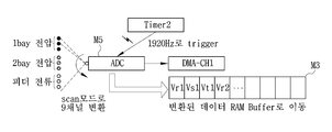
The control unit M1 includes the ADC M5 and the ADC M5 is controlled by the three-phase voltage values R and R of the first and second power sources sensed by the first through sixth voltage sensors V1 through V6, S, T) and the first to third current sensors CT1 to CT3 can sequentially receive the three-phase current values of the system load power. Alternatively, the ADC M5 may be provided outside the control unit M1.
As shown in FIG. 3, the ADC M5 includes a plurality of channels (for example, 9 channels) receiving three-phase voltage values of the first and second power sources and three-phase current values of the system load power source, And sequentially converts the information input to each channel to the control unit M1.
Then, the controller M1 sequentially receives the three-phase voltage values of the digitally-converted first and second power sources and the three-phase current value of the system load power source, and stores them in the storage unit M3.
>> Switching between system power
When the first to third current sensors CT1 to CT3 detect the current image formation on at least one of the three-phase line of the first power source during the use of the first power source as the main power source, 6 switches SW1 to SW6 to supply the second power source, which is a standby power source, to the common three-phase line. Here, if there is no current image formation in the main power source, the control unit M1 continuously supplies the main power source to the common three-phase line.
When the control unit M1 senses that the first power source is turned on by the detection information of the first to third voltage sensors VT1 to VT3 during use of the second power source as the standby power source, To 6) so that the first power source, which is the main power source, is supplied again to the common three-phase line. As described above, in the present invention, it is possible to prepare for a local power failure in which a power failure occurs in one of double buses in a customer who is supplied with two lines of uninterruptible power supply.
The control unit M1 can perform power switching from the main power source to the standby power source within 8 cycles based on the frequency of the commercial power source.
>> Emergency Power Switching Function
However, since a blackout occurs in both of the double buses (first and second power sources) at the time of the wide-area power interruption, shortening of the blackout can be expected even when the power between the bus lines is switched. In the present invention, the emergency generator (EV) is provided in case of such a case, and the power failure time can be reduced by using the emergency power source in case of power failure of the two bus bars. This will be described below.
When the control unit M1 senses current image formation on at least one line of the second power source while the first power source is not being used during the use of the second power source as the standby power source, the control unit M1 controls the seventh switch SW7, Provide emergency power to the line.
The controller M1 detects that the first power source is not recovered by the three-phase voltage values sensed by the first to third voltage sensors VT1 to VT3 and the first to third current sensors CT1 to CT3, 3 senses current imaging of at least one line of the second power source.
At this time, the controller M1 controls the phase voltages of the first and second power sources, the currents of the phases of the system load power, the contacts of the first to sixth switches SW1 to SW6, The contact of the switch SW1 and the voltage of the emergency power source can be further recorded in the storage section M3. At this time, the controller M1 controls the contacts of the switches, so that the coordination information can be known. Further, the voltage of the emergency power source can be further sensed by a separate voltage sensor (not shown).
The control unit M1 can directly apply the emergency power from the emergency generator EV to the power supply line within a predetermined time (e.g., 10 seconds) when the first and second power supplies are turned off. Here, the control unit M1 can open the first to sixth switches SW1 to SW6 so that the first and second power sources can completely block the power source line of the load.
However, the control unit M1 may operate the emergency generator EV in advance in case of trial operation of the emergency generator EV, load switching operation, or supplying the first or second power source and the emergency power source in parallel to the supply power source line, When the constant voltage constant frequency is established at the power source and the synchronization between the electric power source and the emergency power source is established, the emergency power source may be supplied.
When at least one of the first power source and the second power source is recovered during use of the emergency power source, the control unit M1 short-circuits the corresponding one of the first to sixth switches SW1 to SW6, .
>> Conversion history function
The control unit M1 may control the first to the third power supplies for a predetermined time (for example, one second) before and after the switching operation in the switching operation from the first power source to the second power source or in the switching operation from the second power source to the first power source 6 voltage sensors VT1 to 6 and the first to third current sensors CT1 to CT3, the voltage of the first and second power sources, the current of the system load power source, To the storage unit M3, the switching time between the contact points of the switches SW1 to SW6 and the first and second power sources. Here, the switching time may be a time required for supplying a different power from the one power source after the power source of the first and second power sources is stopped.
The control unit M1 controls the switching unit M3 to switch the contact information of the seventh switch SW7, the voltage information of the emergency power source, and the time power to the time power source in the switching operation from the first power source or the second power source to the emergency power source You can record more.
In addition, the controller M1 may further record the current waveforms of the first and second power sources of the first 10 seconds and the common power source in the storage unit M3 after the booting operation.
Here, the storage unit M3 may be provided outside the automatic load switching device. When storing the above-described record information in the internal storage M3, the control unit M1 may transmit at least a part of the record information to the external terminal through the communication unit M2.
>> Load side phase loss warning function
On the other hand, the first to third current sensors CT1 to CT3 are provided on the load side so as to switch from the main power source to the standby power source, even if the image is formed on the load side of the customer. However, in the case of image formation on the load side, current image formation occurs again even after switching to the standby power source. In other words, in the case of the current image formation on the load side, the phase-lag state is maintained regardless of switching to the main power source and the standby power source. On the other hand, since the ALTS (Auto Load Transfer Switch) uses a motor charge method, a charge time of about 10 seconds to 20 seconds is required although there is a slight difference depending on the specific charge method. Therefore, when the above-described continuous switching operation is performed by current image formation on the load side, there occurs a power failure situation in which the cause is not known.
In order to prevent such a problem, the control unit M1 according to the present invention senses the first power source during the use of the second power source, and when the second power source is again switched to the first power source, It is determined that the current is a current image on the load side and the further switching operation is interrupted (Locked).
At this time, the control unit M1 may display a warning message on the display unit M5 to notify the load side current image formation such as "Open Phase I Lock ", for example, and notify the manager of the load side current image formation through the communication unit M2.
The control unit M1 can effectively operate each function by controlling priorities of respective functions such as monitoring, control, communication, display, and resource management by applying RTOS, which is a real-time operating system.
Specifically, the control unit M1 can control the priority of each function execution so as to preferentially process the relay and control in any state as shown in Table 1 below.

The battery Bat is charged by a power source of at least one of a system load power source and an emergency power source and is connected to a control unit M1, first to sixth voltage sensors V1 to V6, first to third current sensors CT1 to CT3 ) And the communication section (M2) of the automatic load switching device.
On the other hand, in the above-described example, the case where the emergency power source is used at the time of current imaging of the first and second power sources has been described as an example. Alternatively, however, the emergency power generated by the self-generating system, such as photovoltaic power generation, can be used for normal load sharing.
In the above example, the control unit M1 automatically switches between the grid power sources and switches to the emergency power source. However, when the manual control is selected, the control unit M1 notifies the manager of the error or operation state information through the display unit M5 or the communication unit M2, and switches between the system power supply and the emergency power supply . ≪ / RTI >
As described above, according to the embodiment of the present invention, the supply power can be automatically switched to the first power source, the second power source, or the emergency power source by using the parallel power supply of the first and second power sources and the emergency power source, The power failure time can be shortened when a problem occurs. Accordingly, the present invention relieves the conventional problem that an excessive emergency generator is used or an additional power loss occurs due to the manual measurement and judgment of the cause analysis and the restoration analysis by the facility manager.
In addition, the embodiment of the present invention can supply the emergency power supply at the time of the wide-area power outage in which a power failure occurs in both of the double buses (first and second power sources) or when the maximum use power is reached due to contract power shortage, Can be reduced.
In addition, the embodiment of the present invention can provide power information recording at the time of power switching to provide an accident cause and an operation reason, thereby helping the manager to make quick decisions and reducing power supply loss as much as possible.
In addition, the embodiment of the present invention can prevent the problem of continuous switching operation due to the current image formation on the load side rather than the current image formation between the first power source and the second power source, thereby reducing the power failure of the consumer and protecting the product mechanism .
Hereinafter, an automatic load switching control method according to an embodiment of the present invention will be described with reference to FIG. 4 is a flowchart illustrating an automatic load switching on / off control method according to an embodiment of the present invention.
Referring to FIG. 4, the controller M1 uses the main current source (first power source) as the system load power, while using the current value by the first to third current sensors CT1 to CT3, At least one line of the commercial line is monitored for the current image formation (S410).
The control section M1 opens the first to third switches SW1 to SW3 and short-circuits the fourth to sixth switches SW4 to SW6 to detect the presence of the standby power source And stores the switching record in the storage unit M3 (S420). More specifically, the control section M1 controls the first through sixth voltage sensors V1 through V6 and the first through third currents V1 through V6 for a predetermined time (for example, 1 second) before and after the second power source is supplied to the common three- By referring to the detection information of the sensors CT1 to CT3, the voltage of the first and second power sources, the current of the grid load power source, and the contacts of the first to sixth switches SW1 to SW6 are written to the storage unit M3 can do.
The control unit M1 monitors whether the first power source is turned on and whether the second power source is turned on after switching the system load power source to the second power source (S430 to S440). At this time, the controller M1 may check whether the first power source is turned on by using the voltage value of the first power source sensed by the first to third voltage sensors VT1 to VT3. Further, the controller Ml monitors whether or not current is established in at least one of the three-phase line of the second power source by using the current value by the first to third current sensors CT1 to CT3.
If the first power source is restored (YES in S430), the control unit M1 switches the system load power source to the first power source and stores the switching record in the storage unit M3 (S450). Specifically, the controller M1 controls the phase voltages of the first and second power sources, the currents of the phases of the system load power, and the currents of the first to sixth switches SW1 to SW6, respectively, for a predetermined time before and after switching to the first power source The contact point can be recorded in the storage section M3.
If the controller M1 detects the current image formation again within a few minutes, the control unit M1 determines that the image is a current image on the load side, stops the further switching operation, locks the load side A warning message indicating the current image formation can be displayed on the display section M5.
The control unit M1 supplies the emergency power generated from the emergency generator EV to the power line of the load and stores the switching record when the image forming operation has occurred in the second power source (S440) And stores it in the unit M3 (S460).
At this time, when the emergency power source is not supplied to the power source line of the load, the control unit M1 short-circuits the seventh switch SW7 to supply the emergency power source to the power source line of the load. In addition, when supplying power from the emergency power source and the system load power source to the load power line in parallel, no separate switch control is performed or only the first to sixth switches SW1 to SW6 can be opened. In addition, the control unit M1 controls the phase voltages of the first and second power sources, the currents of the phases of the system load power source, and the contacts of the first to sixth switches SW1 to SW6, for the predetermined time before and after the power source is switched to the emergency power source, It is possible to record at least one of the voltage of the emergency power source and the contact of the seventh switch SW1 in the storage section M3.
The controller M1 monitors whether one of the first and second power supplies is turned on during the supply of the emergency power (S470). At this time, the controller Ml may determine whether one of the first and second power supplies is turned on by using the sensing information of the first to sixth voltage sensors V1 to V6.
When one of the first and second power supplies is recovered, the controller Ml supplies the recovered power to the system load power (S480). At this time, when both the first power source and the second power source are restored, the control unit M1 may preferentially supply the first power source, which is the main power source, to the system load power source. In addition, when the recovered power source is the second power source, monitoring of the first power source is performed, and when the first power source is recovered, the operation of switching the system load power source to the first power source can be further performed.
As described above, according to the embodiment of the present invention, the power supply can be automatically switched to the first power source, the second power source, or the emergency power source by using the load state detection result, so that the power failure time can be shortened when the power source trouble occurs.
In addition, the embodiment of the present invention can supply the emergency power supply at the time of the wide-area power outage in which a power failure occurs in both of the double buses (first and second power sources) or when the maximum use power is reached due to contract power shortage, Can be reduced.
In addition, the embodiment of the present invention can provide power information recording at the time of power switching to provide an accident cause and an operation reason, thereby helping the manager to make quick decisions and reducing power supply loss as much as possible.
In addition, the embodiment of the present invention can prevent the problem of continuous switching operation due to the current image formation on the load side rather than the current image formation between the first power source and the second power source, thereby reducing the power failure of the consumer and protecting the product mechanism .
While the present invention has been described in detail with reference to the accompanying drawings, it is to be understood that the invention is not limited to the above-described embodiments. Those skilled in the art will appreciate that various modifications, Of course, this is possible. Accordingly, the scope of protection of the present invention should not be limited to the above-described embodiments, but should be determined by the description of the following claims.
Claims (9)
A plurality of voltage sensors connected to one ends of the plurality of switches to detect respective voltages of the first power source and the second power source;
Three current sensors for detecting currents in different phases of the system load power supplied to the load through the transformer from the other end of the plurality of switches connected to the common three-phase line connected in common to the first power source and the second power source; And
Detecting a current image formation on at least one of the three-phase line of the first power source by using the detection information by the current sensor, and controlling the plurality of switches at the time of detecting the current image formation, 2, and the phase voltage of the first and second power supplies, the current of the first phase, the phase current of the second power source, and the phase current of the first power source are referred to by sensing information of the plurality of voltage sensors and the current sensor for a predetermined time before and after supplying the second power source And a control unit
And an automatic load switching device.
An emergency generator generating an emergency power source; And
Further comprising an emergency control switch for selectively supplying power generated from the system load power source or the emergency power source to the power source line of the load under the control of the control unit,
Wherein the control unit controls the emergency control switch to supply the emergency power source to the power line of the load when the voltage sensor and the current sensor detect occurrence of an image formation in both of the first and second power sources Automatic load switching device.
Wherein at least one of the contact information of the emergency control switch and the voltage of the emergency power source is further recorded in the storage section before and after the supply of the emergency power source.
And a second power source for supplying power to the first power source, the second power source for supplying power to the second power source, the second power source for supplying power to the second power source, Power supply,
The currents of the first and second power sources, the currents of the plurality of switches, the contacts of the plurality of switches, and the currents of the first and second power sources by the sensing information of the plurality of voltage sensors and the current sensor for a predetermined time before and after the first power source is re- And writes the switching time from the second power source to the first power source to the storage unit.
And a warning is displayed to warn the display unit of a predetermined load side current image formation when it is determined that a current image is formed on the load side at the time of current image formation of the first power source after the first power source is re-supplied.
Further comprising: an ADC for sequentially receiving and digitally converting detection information of the plurality of voltage sensors and detection information of the current sensor by a plurality of channels,
Wherein the control unit sequentially stores the sensed information digitally converted by the ADC in the storage unit.
Sensing current image formation on at least one line of the three-phase line of the first power source using sensing information by the current sensor;
Controlling the plurality of switches to supply the second power to the common three-phase line when current imaging is detected; And
The currents of the first and second power sources, the currents of the plurality of switches, the switching points of the plurality of switches, and the switching of the plurality of switches by referring to the sensing information of the plurality of voltage sensors and the current sensor for a predetermined time before and after supplying the second power. Recording the time in the storage unit
Wherein the automatic load switching control method comprises:
When an abnormality is detected in both of the first and second power sources by the plurality of voltage sensors and the current sensor, an emergency power supply, which is an output of an emergency generator generating an emergency power by controlling the emergency control switch, Step to supply to line
Further comprising the steps of:
Further comprising the step of recording at least one of the contact information of the emergency control switch and the voltage of the emergency power supply in the storage unit in the switching operation to the emergency power supply
Further comprising the steps of:
Priority Applications (1)
| Application Number | Priority Date | Filing Date | Title |
|---|---|---|---|
| KR1020150106312A KR20170013541A (en) | 2015-07-28 | 2015-07-28 | Apparatus and Control Method for Transferring Automatic Load Switch |
Applications Claiming Priority (1)
| Application Number | Priority Date | Filing Date | Title |
|---|---|---|---|
| KR1020150106312A KR20170013541A (en) | 2015-07-28 | 2015-07-28 | Apparatus and Control Method for Transferring Automatic Load Switch |
Publications (1)
| Publication Number | Publication Date |
|---|---|
| KR20170013541A true KR20170013541A (en) | 2017-02-07 |
Family
ID=58108079
Family Applications (1)
| Application Number | Title | Priority Date | Filing Date |
|---|---|---|---|
| KR1020150106312A KR20170013541A (en) | 2015-07-28 | 2015-07-28 | Apparatus and Control Method for Transferring Automatic Load Switch |
Country Status (1)
| Country | Link |
|---|---|
| KR (1) | KR20170013541A (en) |
Cited By (2)
| Publication number | Priority date | Publication date | Assignee | Title |
|---|---|---|---|---|
| KR101989774B1 (en) * | 2018-12-27 | 2019-06-17 | 주식회사 지엔이피에스 | Hybrid Closed Transition Transfer Switch System Using Mechanical And Electronic Switches |
| CN113131603A (en) * | 2021-04-21 | 2021-07-16 | 高奇 | Intelligent dual-power electronic fast converter and conversion method |
-
2015
- 2015-07-28 KR KR1020150106312A patent/KR20170013541A/en not_active Application Discontinuation
Cited By (2)
| Publication number | Priority date | Publication date | Assignee | Title |
|---|---|---|---|---|
| KR101989774B1 (en) * | 2018-12-27 | 2019-06-17 | 주식회사 지엔이피에스 | Hybrid Closed Transition Transfer Switch System Using Mechanical And Electronic Switches |
| CN113131603A (en) * | 2021-04-21 | 2021-07-16 | 高奇 | Intelligent dual-power electronic fast converter and conversion method |
Similar Documents
| Publication | Publication Date | Title |
|---|---|---|
| CN107819357B (en) | Isolated parallel UPS system with fault location detection | |
| JP6506394B2 (en) | Uninterruptible power system | |
| JP2848554B2 (en) | System for supplying power to a device and method for evaluating the life and capacity of a power storage device | |
| EP3989384B1 (en) | Uninterrupted power supply (ups) system and method of operating the same | |
| US9935463B2 (en) | Redundant point of common coupling (PCC) to reduce risk of microgrid's islanding | |
| EP1465318A2 (en) | Uninterruptible power supply system | |
| JP2009112080A (en) | Power switching device and power system using the same | |
| CN113691010A (en) | Redundant power supply system and control method | |
| WO2014083788A1 (en) | Bidirectional converter | |
| KR20170013541A (en) | Apparatus and Control Method for Transferring Automatic Load Switch | |
| WO2018105875A1 (en) | Power conversion apparatus and uninterruptible power supply comprising same | |
| JP2019205309A (en) | Power supply system | |
| CN102044978A (en) | Power supply circuit and monitoring protection method thereof | |
| JP2014128165A (en) | Insulation determination system | |
| JP2008220136A (en) | Protection relay system of distribution system | |
| KR20170003334A (en) | Automatic load transfer switch and control method thereof | |
| JP5858236B2 (en) | Battery system | |
| KR20190102467A (en) | System of uninterrupted construction using energy storage system and power control system | |
| EP2903129B1 (en) | Multi-type and multi-mode automatic transfer switching apparatus and method thereof | |
| RU2215355C1 (en) | No-break power installation for railway automatic-control systems | |
| US20230187925A1 (en) | Electrical protection systems and methods having improved selectivity | |
| JP7458333B2 (en) | Uninterruptible power switching device, test equipment for uninterruptible power switching device | |
| CN114709853B (en) | Power supply system and method | |
| CN211880158U (en) | Power supply system | |
| JP5662229B2 (en) | Transformer device for movement |
Legal Events
| Date | Code | Title | Description |
|---|---|---|---|
| A201 | Request for examination | ||
| E601 | Decision to refuse application |