KR20170010607A - System and method for controlling working speed of machine tool - Google Patents
System and method for controlling working speed of machine tool Download PDFInfo
- Publication number
- KR20170010607A KR20170010607A KR1020150102456A KR20150102456A KR20170010607A KR 20170010607 A KR20170010607 A KR 20170010607A KR 1020150102456 A KR1020150102456 A KR 1020150102456A KR 20150102456 A KR20150102456 A KR 20150102456A KR 20170010607 A KR20170010607 A KR 20170010607A
- Authority
- KR
- South Korea
- Prior art keywords
- distance
- corner
- conditional expression
- machining
- tool
- Prior art date
Links
Images

Classifications
-
- B—PERFORMING OPERATIONS; TRANSPORTING
- B23—MACHINE TOOLS; METAL-WORKING NOT OTHERWISE PROVIDED FOR
- B23Q—DETAILS, COMPONENTS, OR ACCESSORIES FOR MACHINE TOOLS, e.g. ARRANGEMENTS FOR COPYING OR CONTROLLING; MACHINE TOOLS IN GENERAL CHARACTERISED BY THE CONSTRUCTION OF PARTICULAR DETAILS OR COMPONENTS; COMBINATIONS OR ASSOCIATIONS OF METAL-WORKING MACHINES, NOT DIRECTED TO A PARTICULAR RESULT
- B23Q15/00—Automatic control or regulation of feed movement, cutting velocity or position of tool or work
- B23Q15/007—Automatic control or regulation of feed movement, cutting velocity or position of tool or work while the tool acts upon the workpiece
- B23Q15/08—Control or regulation of cutting velocity
-
- B—PERFORMING OPERATIONS; TRANSPORTING
- B23—MACHINE TOOLS; METAL-WORKING NOT OTHERWISE PROVIDED FOR
- B23Q—DETAILS, COMPONENTS, OR ACCESSORIES FOR MACHINE TOOLS, e.g. ARRANGEMENTS FOR COPYING OR CONTROLLING; MACHINE TOOLS IN GENERAL CHARACTERISED BY THE CONSTRUCTION OF PARTICULAR DETAILS OR COMPONENTS; COMBINATIONS OR ASSOCIATIONS OF METAL-WORKING MACHINES, NOT DIRECTED TO A PARTICULAR RESULT
- B23Q15/00—Automatic control or regulation of feed movement, cutting velocity or position of tool or work
- B23Q15/007—Automatic control or regulation of feed movement, cutting velocity or position of tool or work while the tool acts upon the workpiece
- B23Q15/12—Adaptive control, i.e. adjusting itself to have a performance which is optimum according to a preassigned criterion
-
- G—PHYSICS
- G05—CONTROLLING; REGULATING
- G05B—CONTROL OR REGULATING SYSTEMS IN GENERAL; FUNCTIONAL ELEMENTS OF SUCH SYSTEMS; MONITORING OR TESTING ARRANGEMENTS FOR SUCH SYSTEMS OR ELEMENTS
- G05B19/00—Programme-control systems
- G05B19/02—Programme-control systems electric
- G05B19/18—Numerical control [NC], i.e. automatically operating machines, in particular machine tools, e.g. in a manufacturing environment, so as to execute positioning, movement or co-ordinated operations by means of programme data in numerical form
- G05B19/416—Numerical control [NC], i.e. automatically operating machines, in particular machine tools, e.g. in a manufacturing environment, so as to execute positioning, movement or co-ordinated operations by means of programme data in numerical form characterised by control of velocity, acceleration or deceleration
Abstract
Description
본 발명은 공작기계의 가공속도 제어시스템 및 제어방법에 관한 것이다.The present invention relates to a machining speed control system and a control method of a machine tool.
공작기계는 각종 절삭 가공방법 또는 비절삭 가공방법으로 금속 또는 비금속의 소재(이하 모재)를 적당한 공구를 사용하여 형상 및 치수로 가공하던가 또는 더욱 정밀한 가공을 추가할 목적으로 사용되는 기계를 말한다.A machine tool is a machine that is used for machining metal or nonmetal materials (hereinafter referred to as "base material") into shapes and dimensions by using various cutting or non-cutting machining methods, or for adding more precise machining.
이러한 공작기계는 산업 전반에 걸쳐 자동화 및 수치제어화(Numerical Control)가 급속히 진전되고 있으며, 이에 더해 컴퓨터 수치제어(Computerized Numerical Control)화가 적용되어, 산업현장의 폭 넓은 수요에 힘입어 시장이 급속도로 확대되고 있는 추세이다.Such machine tools are rapidly progressing in automation and numerical control throughout the industry. In addition, computerized numerical control (PC) has been applied, and the market is rapidly increasing The trend is expanding.
이러한 공작기계에서, 모재의 가공은 작업자가 생성한 가공 프로그램에 의해 이뤄지며, 상기 가공 프로그램에는 가공시 사용할 공구, 공구의 이송속도 및 스핀들 회전속도 및 가공경로 등이 포함되어 있다.In such a machine tool, processing of the base material is performed by a machining program generated by an operator, and the machining program includes a tool to be used in machining, a feed speed of the tool, a spindle rotational speed, and a machining path.
여기서, 공구의 변경 없이 하나의 공구에 의해 가공하는 부분을 하나의 가공 공정이라 부르며, 일반적으로, 이러한 하나의 가공 공정 내에서는 일정한 공구의 이송속도 및 일정한 스핀들 회전속도로 가공이 진행된다. Here, the portion to be processed by one tool without changing the tool is called a machining process, and in general, machining proceeds at a constant tool feed rate and a constant spindle rotational speed in this one machining process.
이러한 경우, 공구의 단위시간당 절삭량은 가공 경로와 피절삭물의 형상에 따라 달라진다. In this case, the amount of cutting per unit time of the tool depends on the machining path and the shape of the workpiece.
예를 들어, 코너 가공 또는 일정하지 않은 두께로 형성되는 형상을 가공하는 경우는 절삭량이 일정하지 않다. 단위시간당 절삭량의 변동은 공구에 걸리는 가공 부하 변동을 발생시키며, 이로 인해 공구는 과도한 부하나 충격하중을 받게되어 공구의 마모 및 파손을 촉진시키게 한다.For example, when machining a shape that is formed with a corner or a non-uniform thickness, the amount of cut is not constant. Variations in the amount of machining per unit time result in variations in the machining load on the tool, which causes the tool to be subjected to excessive load or impact loads, thereby promoting tool wear and tear.
이와 같은 문제를 해결하기 위해, 공구에 걸리는 가공 부하에 따라 가공 속도(이송 속도)를 변경해주는 적응속도제어 시스템이 제안되고 있다. 그러나, 이러한 기존의 제어 시스템은 가공 부하에 따라 이송 속도를 자동으로 조절해 주지만, 속도가 부드럽게 변경되어야 하는 직선가공과 속도가 빠르게 변경되어야 하는 코너가공 부위를 모두 만족시킬 수 없는 문제점을 갖고 있다.In order to solve such a problem, an adaptive speed control system which changes the machining speed (feed rate) according to the machining load applied to the tool has been proposed. However, these conventional control systems have problems in that the feed speed is automatically adjusted according to the machining load, but the straight machining in which the speed needs to be changed smoothly and the corner machining part in which the speed needs to be changed quickly can not all be satisfied.
즉, 기존의 가공 속도 제어 시스템은 가공 공정 단위인 황삭 가공, 정삭 가공, 포켓 가공 등에 따라 다르게 적용될 수 있지만, 공정 내에 존재하는 컨투어(contour) 단위인 직선 가공, 곡선 가공, 코너 가공 등에 따라 달리 적용할 수는 없다.In other words, the existing machining speed control system can be applied differently depending on the roughing, finishing, and pocket machining of the machining process unit, but it is differently applied according to the contour unit in the process such as straight machining, curve machining, corner machining I can not.
이러한 기존의 가공속도 제어 시스템에 의한 직선 가공 시 급격한 속도 변화는 조도에 악영향을 끼치며, 코너에서의 느린 속도 변화는 제때에 속도 감속이 일어나지 않아 공구 파손으로 이어지기 때문에 컨투어의 형상에 따른 가공속도 제어 시스템이 필요한 실정이다.The rapid speed change in the linear machining by the conventional machining speed control system adversely affects the roughness and the slow speed change at the corner leads to the breakage of the tool because the speed deceleration does not occur in time, System is necessary.
본 발명은 상기와 같은 문제점을 해결하기 위해 안출한 것으로서, 본 발명의 목적은 가공 경로의 형상에 따라 가공 속도(이송 속도)를 제어하여, 공구에 대한 의도하지 않은 가공 부하를 제거하여 공구 수명을 향상시키고 가공 신뢰성 및 정밀성을 높일 수 있는 공작기계의 가공속도 제어시스템 및 제어방법을 제공함에 있다.SUMMARY OF THE INVENTION The present invention has been made in order to solve the above-mentioned problems, and an object of the present invention is to provide an apparatus and a method for controlling the machining speed (feed rate) And to provide a machining speed control system and a control method of a machine tool capable of improving machining reliability and precision.
상기 목적을 달성하기 위해서 본 발명은, 모재를 가공하는 공구; 상기 공구를 회전시키는 스핀들부; 상기 스핀들부 또는 모재를 이송시키는 이송부; 상기 스핀들부 및 이송부와 연계되며, 가공 부하와 형상을 판단하여 가공 속도를 조절하는 제어부;를 포함하는 공작기계의 가공속도 제어시스템을 제공한다.According to an aspect of the present invention, A spindle portion for rotating the tool; A transferring part for transferring the spindle part or the base material; And a control unit coupled to the spindle unit and the transfer unit for determining a machining load and a shape to adjust a machining speed.
또한, 상기 제어부는 가공시 상기 공구의 가공부하를 검출하는 부하수집부; 상기 부하수집부에 의해 검출되는 부하의 변화 및 이송 거리에 근거하여 모재 가공 부위 형상이 변하는 코너부분인지 판단하는 형상판단부; 및 상기 형상판단부의 데이터, 현재 가공속도, 지령된 가공속도 및 설정 데이터에 근거하여 가공속도를 산출하는 가공속도계산부;를 포함할 수 있다.Further, the control unit may include: a load collecting unit for detecting a machining load of the tool during machining; A shape determining unit that determines whether the shape of the base material processing portion varies depending on a change in the load detected by the load collecting unit and a transfer distance; And a machining speed calculator for calculating a machining speed based on the data of the shape determining unit, the current machining speed, the instructed machining speed, and the setting data.
또한, 상기 형상판단부는 하기 조건식 1에 의해 코너가 시작된 것으로 판단하고, 하기 조건식 2에 의해 코너를 벗어난 것으로 판단할 수 있다.In addition, the shape determination unit may determine that the corner has started by the following
<조건식 1><
E > eE> e
<조건식 2><
E < sE <s
여기서, E는 기설정된 직선거리에서 상기 부하수집부에 의해 공구부하가 급격히 증가되는 순간에 공구가 위치한 거리를 뺀 거리, e는 기설정된 직선거리에서 이송할 거리, s는 기설정된 직선거리에서 이송한 거리를 나타낸다.Where E is a distance obtained by subtracting the distance at which the tool is located at a moment when the tool load is rapidly increased by the load collecting unit at a predetermined straight distance, e is a distance to be traversed at a predetermined straight distance, and s is a predetermined straight distance Represents a distance.
또한, 상기 형상판단부는 하기 조건식 3에 의해 코너가 시작된 것으로 판단하고, 하기 조건식 2에 의해 코너를 벗어난 것으로 판단할 수 있다.Further, the shape determination unit may determine that the corner has started by the following conditional expression (3), and may determine that the corner is out of order by the following conditional expression (2).
<조건식 3><
E > eE> e
<조건식 2><
E < sE <s
여기서, E는 기설정된 직선거리에서 공구 직경의 1/3 내지 공구직경 거리를 뺀 거리, e는 기설정된 직선거리에서 이송할 거리, s는 기설정된 직선거리에서 이송한 거리를 나타낸다.Where E is the distance obtained by subtracting the tool diameter distance from 1/3 of the tool diameter at the preset straight distance, e is the distance to be traversed at the predetermined straight distance, and s is the distance traveled from the preset straight distance.
또한, 상기 형상판단부는 하기 조건식 4에 의해 코너가 시작된 것으로 판단하고, 하기 조건식 2에 의해 코너를 벗어난 것으로 판단할 수 있다.In addition, the shape determination unit may determine that the corner has started by the following conditional expression (4), and may determine that the corner is out of order by the following conditional expression (2).
<조건식 4><
E > e, E = D/3/sinθ + D/2/sinθE> e, E = D / 3 / sin? + D / 2 / sin?
<조건식 2><
E < sE <s
여기서, D는 공구의 직경, θ는 코너각, e는 기설정된 직선거리에서 이송할 거리, s는 기설정된 직선거리에서 이송한 거리를 나타낸다.Where D is the diameter of the tool, θ is the corner angle, e is the distance to be traversed at the preset straight distance, and s is the distance traveled from the preset straight distance.
또한, 상기 가공속도계산부는 하기의 조건식 5로써 가공속도를 계산할 수 있다.Further, the machining speed calculator may calculate the machining speed using the following conditional expression (5).
<조건식 5><
Vc= Kp*Lc + Ki*Lc*t + Kd*(Lc-Lp)/tVc = Kp * Lc + Ki * Lc * t + Kd * (Lc-Lp) / t
여기서, Vc는 지령 속도, Kp는 비례게인(proportional gain), Ki는 적분게인(integral gain), Kd는 미분게인(differential gain), Lc는 현재 부하값, Lp는 이전 부하값, t는 계산 주기를 나타낸다.Where Kc is the proportional gain, Ki is the integral gain, Kd is the differential gain, Lc is the current load value, Lp is the previous load value, t is the calculation period .
또한, 상기 가공속도계산부는 직선부와 코너부에서 각각 다르게 설정된 Kp, Ki 및 Kd 값을 적용할 수 있다.Also, the machining speed calculator may apply Kp, Ki, and Kd values set differently in the straight line portion and the corner portion, respectively.
한편, 본 발명은 속도제어 기능이 온(on)되어 있다면, 부하수집부로써 가공 부하를 수집하고, 형상판단부로써 가공영역이 코너부분인지를 판단하는 단계; 및 가공속도계산부로써 상기 형상판단부의 데이터, 현재 가공속도, 지령된 가공속도 및 설정 데이터에 근거하여 가공속도를 산출하는 단계;를 포함하는 공작기계의 가공속도 제어방법을 제공할 수 있다.According to another aspect of the present invention, there is provided a method of manufacturing a semiconductor device, the method comprising: collecting a machining load with a load collection unit if a speed control function is on; And calculating a machining speed on the basis of the data of the shape determining unit, the current machining speed, the instructed machining speed, and the setting data as the machining speed calculator, and a machining speed controlling method of the machine tool.
또한, 상기 가공영역이 코너부분인지를 판단하는 단계는 현재 가공영역이 미소블록인지 판단하는 단계; 이 후, 미소블록이 아니라면, 현재 블록과 다음 블록이 이루는 각도를 계산하는 단계; 상기 각도가 기설정된 각도 범위 내에 존재하는지 판단하는 단계; 및 이 후, 기설정된 각도 범위인지 여부에 따라 다른 속도 제어 게인 값을 적용하는 단계;를 포함할 수 있다.The step of determining whether the machining area is a corner may include determining whether the machining area is a micro block; Thereafter, if not a small block, calculating an angle between the current block and the next block; Determining whether the angle is within a predetermined angle range; And then applying a different speed control gain value depending on whether or not it is a predetermined angle range.
또한, 상기 가공영역이 코너부분인지를 판단하는 단계는 상기 형상판단부에서 하기 조건식 1에 의해 코너가 시작된 것으로 판단하고, 하기 조건식 2에 의해 코너를 벗어난 것으로 판단할 수 있다.In the step of determining whether the machining area is a corner part, it is determined that the corner has been started by the following
<조건식 1><
E > eE> e
<조건식 2><
E < sE <s
여기서, E는 기설정된 직선거리에서 상기 부하수집부에 의해 공구부하가 급격히 증가되는 순간에 공구가 위치한 거리를 뺀 거리, e는 기설정된 직선거리에서 이송할 거리, s는 기설정된 직선거리에서 이송한 거리를 나타낸다.Where E is a distance obtained by subtracting the distance at which the tool is located at a moment when the tool load is rapidly increased by the load collecting unit at a predetermined straight distance, e is a distance to be traversed at a predetermined straight distance, and s is a predetermined straight distance Represents a distance.
또한, 상기 가공영역이 코너부분인지를 판단하는 단계는 상기 형상판단부에서 하기 조건식 3에 의해 코너가 시작된 것으로 판단하고, 하기 조건식 2에 의해 코너를 벗어난 것으로 판단할 수 있다.In the step of determining whether the machining area is a corner, it is determined that the corner has been started in the shape determining unit according to the following conditional expression (3), and it can be determined that the corner is out of the following conditional expression (2).
<조건식 3><
E > eE> e
<조건식 2><
E < sE <s
여기서, E는 기설정된 직선거리에서 공구 직경의 1/3 내지 공구직경 거리를 뺀 거리, e는 기설정된 직선거리에서 이송할 거리, s는 기설정된 직선거리에서 이송한 거리를 나타낸다.Where E is the distance obtained by subtracting the tool diameter distance from 1/3 of the tool diameter at the preset straight distance, e is the distance to be traversed at the predetermined straight distance, and s is the distance traveled from the preset straight distance.
또한, 상기 가공영역이 코너부분인지를 판단하는 단계는 상기 형상판단부에서 하기 조건식 4에 의해 코너가 시작된 것으로 판단하고, 하기 조건식 2에 의해 코너를 벗어난 것으로 판단할 수 있다.In the step of determining whether the machining area is a corner, it is determined that the corner has been started by the following conditional expression (4) in the shape determination section, and it can be determined that the corner is out of the following conditional expression (2).
<조건식 4><
E > e, E = D/3/sinθ + D/2/sinθE> e, E = D / 3 / sin? + D / 2 / sin?
<조건식 2><
E < sE <s
여기서, D는 공구의 직경, θ는 코너각, e는 기설정된 직선거리에서 이송할 거리, s는 기설정된 직선거리에서 이송한 거리를 나타낸다.Where D is the diameter of the tool, θ is the corner angle, e is the distance to be traversed at the preset straight distance, and s is the distance traveled from the preset straight distance.
또한, 상기 가공속도를 산출하는 단계에서 상기 가공속도계산부는 하기의 조건식 5로써 가공속도를 계산할 수 있다.Further, in the step of calculating the machining speed, the machining speed calculating unit may calculate the machining speed by the following conditional expression (5).
<조건식 5><
Vc= Kp*Lc + Ki*Lc*t + Kd*(Lc-Lp)/tVc = Kp * Lc + Ki * Lc * t + Kd * (Lc-Lp) / t
여기서, Vc는 지령 속도, Kp는 비례게인(proportional gain), Ki는 적분게인(integral gain), Kd는 미분게인(differential gain), Lc는 현재 부하값, Lp는 이전 부하값, t는 계산 주기를 나타낸다.Where Kc is the proportional gain, Ki is the integral gain, Kd is the differential gain, Lc is the current load value, Lp is the previous load value, t is the calculation period .
본 발명에 따르면, 가공 부하와 가공 형상을 판단하여 속도 응답 속도(게인)를 조절함으로써 가공 형상에 따른 속도 제어를 통해 평면의 표면 조도 향상과 코너에서의 공구 및 스핀들 보호 기능을 향상시키는 이점이 있다.According to the present invention, it is possible to improve the surface roughness of the plane surface and improve the tool and spindle protection function at the corner by controlling the speed response speed (gain) by judging the machining load and the machining shape, .
도 1은 본 발명의 실시예에 따른 공작기계의 가공속도 제어시스템을 개략적으로 도시한 도면.
도 2는 본 발명의 실시예에 따른 형상판단부의 판단 과정을 설명하기 위한 예시도.
도 3은 본 발명의 실시예에 따른 공작기계의 가공속도 제어 방법의 플로우 차트.BRIEF DESCRIPTION OF THE DRAWINGS FIG. 1 is a schematic view of a machining speed control system for a machine tool according to an embodiment of the present invention; FIG.
FIG. 2 is an exemplary diagram for explaining a determination process of a shape determination unit according to an embodiment of the present invention; FIG.
3 is a flowchart of a machining speed control method of a machine tool according to an embodiment of the present invention.
이하, 본 발명의 바람직한 실시예는 첨부된 도면을 참조하여 상세하게 설명한다.Hereinafter, preferred embodiments of the present invention will be described in detail with reference to the accompanying drawings.
특별한 정의가 없는 한 본 명세서의 모든 용어는 당업자가 이해하는 용어의 일반적인 의미와 동일하고, 만약 본 명세서에서 사용된 용어가 당해 용어의 일반적인 의미와 충돌하는 경우에는 본 명세서에 사용된 정의에 따른다.Unless defined otherwise, all terms used herein are the same as the generic meanings of the terms understood by those of ordinary skill in the art, and where the terms used herein contradict the general meaning of the term, they shall be as defined herein.
다만, 이하에 기술될 발명은 본 발명의 실시예를 설명하기 위한 것일 뿐 본 발명의 권리범위를 한정하기 위한 것은 아니며, 명세서 전반에 걸쳐서 동일하게 사용된 참조번호들은 동일한 구성요소들을 나타낸다.It is to be understood, however, that the invention is not limited to the disclosed embodiments, but, on the contrary, is intended to be &
도 1은 본 발명의 실시예에 따른 공작기계의 가공속도 제어시스템을 개략적으로 도시한 도면이며, 도 2는 본 발명의 실시예에 따른 형상판단부의 판단 과정을 설명하기 위한 예시도이다.FIG. 1 is a view schematically showing a machining speed control system of a machine tool according to an embodiment of the present invention, and FIG. 2 is an exemplary diagram for explaining a process of determining a shape determining unit according to an embodiment of the present invention.
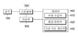
도 1을 참조하면, 실시예는 크게 공구(100), 스핀들부(200), 이송부(300) 및 제어부(400)를 포함할 수 있다.Referring to FIG. 1, the embodiment may include a
상기 공구(100)는 모재(10)를 가공하기 위한 것으로서, 후술할 스핀들부(200)에 장착되며, 이러한 공구(100)의 종류는 다양하게 구비될 수 있다.The
상기 스핀들부(200)는 상기 공구(100)를 회전시켜 모재(10)를 가공하기 위한 구동력을 제공한다.The
상기 이송부(300)는 상기 스핀들부(200) 또는 모재(10)를 이송시키기 위한 구성요소이다.The
상기 제어부(400)는 공작기계의 구동을 제어하며, 구체적으로, 상기 스핀들부(200) 및 이송부(300)와 연계되며, 가공 부하와 형상을 판단하여 가공 속도를 조절할 수 있다.The
즉, 실시예에 따른 제어부(400)는 기존의 제어부와 달리 모재(10) 가공 부분 중 직선부분과 코너부분을 구분하여 가공 속도를 제어할 수 있다.That is, the
이를 위해, 실시예에 따른 제어부(400)는 가공시 상기 공구(100)의 가공부하를 검출하는 부하수집부(410)와, 상기 부하수집부(410)에 의해 검출되는 부하의 변화 및 이송 거리에 근거하여 모재(10) 가공 부위 형상이 변하는 코너부분인지 판단하는 형상판단부(420)와, 상기 형상판단부(420)의 데이터, 현재 가공속도, 지령된 가공속도 및 설정 데이터에 근거하여 가공속도를 산출하는 가공속도계산부(430)를 포함할 수 있다.To this end, the
상기 부하수집부(410)는 공구(100) 또는 스핀들부(200)에 배치되는 센서로써 검출되는 공구(100)의 부하를 전달받을 수 있다.The
상기 형상판단부(420)는 다음과 같이 여러 방법으로써 가공영역 중 코너 부분을 판단할 수 있으며, 이러한 판단은 도 2를 참조하여 설명한다.The
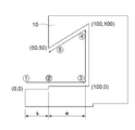
도 2를 참조하면, 모재(10)의 가공영역의 예시가 도시되어 있다. 이러한 가공 영역은 두 개의 코너부분을 가지고 있으며, 이는 예를 들어, 하기의 표와 같이 가공 좌표가 제어부(400)에 사용자게 의해 설정될 수 있다.Referring to Fig. 2, an example of the machining area of the
즉, 도 2를 참조하면, 1번에서 5번으로 순차적으로 공구(100)가 이동되어 모재(10)를 가공할 수 있으며, 공구(100)가 3번에 위치하면 NC로부터 얻을 수 있는 각도는 270°가 되며, 공구(100)가 4번에 위치하면 NC로부터 얻을 수 있는 각도는 315°가 된다.2, the
상기 블록의 각도는 두 선분으로 이루는 평면에서 두 선분이 이루는 각도를 뜻한다.The angle of the block means an angle formed by two line segments in a plane formed by two segment segments.
첫번째로, 상기 형상판단부(420)는 하기 조건식 1에 의해 코너가 시작된 것으로 판단하고, 하기 조건식 2에 의해 코너를 벗어난 것으로 판단할 수 있다.First, the
<조건식 1><
E > eE> e
<조건식 2><
E < sE <s
여기서, E는 기설정된 직선거리에서 상기 부하수집부(410)에 의해 공구 (100)의 부하가 급격히 증가되는 순간에 공구(100)가 위치한 거리를 뺀 거리, e는 기설정된 직선거리에서 이송할 거리, s는 기설정된 직선거리에서 이송한 거리를 나타낸다.Here, E is a distance obtained by subtracting the distance at which the
즉, 도 2에서 2번의 위치가 3번의 위치로 수렴하면, 공구(100)는 또 다른 벽면을 만나게 되므로 공구(100) 부하가 급격히 증가하게 되며, 이 순간의 남은 거리는 E가 된다. s는 공구(100)가 3번을 지나면 0의 값에서 차츰 늘어나게 되며, 그 값이 E보다 커질 경우 코너를 벗어난 것으로 판단할 수 있다.That is, when the second position is converged to the third position in FIG. 2, the
두번째로, 상기 형상판단부(420)는 하기 조건식 3에 의해 코너가 시작된 것으로 판단하고, 하기 조건식 2에 의해 코너를 벗어난 것으로 판단할 수 있다.Secondly, the
<조건식 3><
E > eE> e
<조건식 2><
E < sE <s
여기서, E는 기설정된 직선거리에서 공구(100) 직경의 1/3 내지 공구(100)직경 거리를 뺀 거리, e는 기설정된 직선거리에서 이송할 거리, s는 기설정된 직선거리에서 이송한 거리를 나타낸다.Here, E is a distance obtained by subtracting the diameter of the tool (100) from 1/3 of the diameter of the tool (100) at a predetermined straight distance, e is a distance to be traversed at a predetermined straight distance, s is a distance .
즉, 일반적으로 가공시 절삭 폭이 공구(100) 직경의 1/3 내지 공구(100) 직경이기 때문에 E를 상기와 같이 상수로써 설정할 수 있다. s는 공구(100)가 3번을 지나면 0의 값에서 차츰 늘어나게 되며, 그 값이 E보다 커질 경우 코너를 벗어난 것으로 판단할 수 있다.That is, in general, since the cutting width at the time of machining is 1/3 of the diameter of the
세번째로, 상기 형상판단부(420)는 하기 조건식 4에 의해 코너가 시작된 것으로 판단하고, 하기 조건식 2에 의해 코너를 벗어난 것으로 판단할 수 있다.Thirdly, the
<조건식 4><
E > e, E = D/3/sinθ + D/2/sinθE> e, E = D / 3 / sin? + D / 2 / sin?
<조건식 2><
E < sE <s
여기서, D는 공구(100)의 직경, θ는 코너각, e는 기설정된 직선거리에서 이송할 거리, s는 기설정된 직선거리에서 이송한 거리를 나타낸다.Where D is the diameter of the
즉, 도 2에서 3번 지점에서의 블록 각도는 270°이므로, 절삭폭이 공구(100) 직경의 1/3이라면 E의 값은 공구(100) 직경의 1/3보다 커야 한다. s는 공구(100)가 3번을 지나면 0의 값에서 차츰 늘어나게 되며, 그 값이 E보다 커질 경우 코너를 벗어난 것으로 판단할 수 있다.That is, the block angle at the
즉, 상기 셋 중 어느 하나의 방법으로 실시예는 효과적으로 컨투어가 변하는 지점을 효과적으로 판단할 수 잇다.That is, in any one of the above-described methods, the embodiment can effectively determine the point where the contour changes.
상기 가공속도계산부(430)는 이러한 형상판단부(420)의 판단에 의해 생성된 데이터와 현재 가공속도, 지령된 가공속도 및 설정 데이터에 근거하여 가공속도를 산출할 수 있다.The
구체적으로, 상기 가공속도계산부(430)는 하기의 조건식 5로써 가공속도를 계산할 수 있다.Specifically, the
<조건식 5><
Vc= Kp*Lc + Ki*Lc*t + Kd*(Lc-Lp)/tVc = Kp * Lc + Ki * Lc * t + Kd * (Lc-Lp) / t
여기서, Vc는 지령 속도, Kp는 비례게인(proportional gain), Ki는 적분게인(integral gain), Kd는 미분게인(differential gain), Lc는 현재 부하값, Lp는 이전 부하값, t는 계산 주기를 나타낸다.Where Kc is the proportional gain, Ki is the integral gain, Kd is the differential gain, Lc is the current load value, Lp is the previous load value, t is the calculation period .
여기서, 실시예에 따른 제어부(400)는 상기 Kp, Ki 및 Kd 값을 직선부와 코너부에서 다르게 적용할 수 있다. 이는 상기 형상판단부(420)의 정확한 판단으로부터 기인한다.Here, the
구체적으로, 상기 형상판단부(420)의 판단을 통해 가공 위치가 코너부분인 경우, 직선부분과는 달리 Kd 값의 상승이 필요하다. 왜냐하면, 평면 가공시에는 부하값 입력에 잡음이라 할 수 있는 부하값들이 순간순간 들어오는 경우가 많기 때문에 민감하게 속도조절을 할 필요가 없으므로 Kd 값을 많이 낮추지만, 코너부분의 경우에는 지속적인 부하 상승이 예상되기 때문에 Kd 값을 높여 빠른 속도 조절이 필요하기 때문이다.Specifically, when the machining position is a corner portion through the determination of the
또한, Kp 및 Ki 값 역시 코너부분에서 적절하게 조절되어야 하며, 이에 대한 적절한 함수는 실험에 의해 얻어낼 수 있다.In addition, the Kp and Ki values should also be appropriately adjusted at the corner portions, and an appropriate function can be obtained by experiment.
따라서, 실시예에서는 직선구간의 경우의 Kp, Ki 및 Kd 값과 코너부분에서의 Kp, Ki 및 Kd 값을 다르게 적용할 수 있다. 이러한 각각의 Kp, Ki 및 Kd 값은 실험을 통해 적절하게 얻어낸 값들을 제어부(400)에 미리 저장해 둘 수 있다.Therefore, in the embodiment, Kp, Ki and Kd values in the case of the straight line section and Kp, Ki and Kd values at the corner can be applied differently. The values of Kp, Ki, and Kd can be stored in advance in the
이러한 실시예에 따른 공작기계의 가공속도 제어방법을 설명하자면 다음과 같다.A processing speed control method of a machine tool according to this embodiment will be described as follows.
도 3을 참조하면, 일단 부하에 따른 속도 제어기능이 온(ON)인지를 판단한다(S100).Referring to FIG. 3, it is determined whether the speed control function according to the load is ON (S100).
부하에 따른 속도 제어기능이 온(ON)이면, 부하수집부(410)에서 부하가 증가하는지 정보를 수집하고(S200), 형상판단부(420)에서 가공영역이 직선부분인지 코너부분인지를 주기적으로 판단한다(S300).If the speed control function according to the load is ON, the
이 후, 이러한 형상판단부(420)의 판단에 따라 가공속도계산부(430)에서 가공속도를 산출하여 스핀들부(200)의 회전속도 또는 이송부(300)의 이동속도를 제어할 수 있다(S400).Thereafter, the
여기서, 상기 형상판단부(420)의 판단 단계(S300)는 먼저 현재 이송 블록이 미소블록인지를 판단한다(S310).Here, the determination step S300 of the
미소블록으로 판단되면, 직선부분에 따른 Kp, Ki 및 Kd 값을 적용하고(S320), 이에 따라 가공속도를 산출한다(S400). 이러한 가공속도 산출은 전술한 조건식 5를 통해 수행할 수 있다.Kp, Ki, and Kd values corresponding to the straight line portion are applied (S320), and the machining speed is calculated (S400). This processing speed calculation can be performed through the above-described conditional expression (5).
미소블록이 아닌것으로 판단되면, 현재 블록과 다음 블록이 이루는 각도를 계산하고(S330), 상기 각도가 일정범위 내에 존재하는지 판단하여 일정범위 내라면(S340), 코너부분에 따른 Kp, Ki 및 Kd 값을 적용하고(S350), 일정범위내가 아니라면 직선부분에 따른 Kp, Ki 및 Kd 값을 적용한다(S320).If it is determined that the angle is not within the predetermined range (S340), the angle between the current block and the next block is calculated (S330). If the angle is within the predetermined range (S340), Kp, Ki and Kd (S350). If it is not within the predetermined range, Kp, Ki, and Kd according to the straight line portion are applied (S320).
물론, 상기 방법은 전술한 세 가지의 형상판단부(420)의 판단방법 중 조건식 4 및 조건식 2를 사용하는 세번째 방법이며, 다른 두 가지 판단방법에 따라 Kp, Ki 및 Kd 값의 적용을 꾀할 수 있다.Of course, the above method is a third method using
이상, 상기 설명에 의해 당업자라면 본 발명의 기술적 사상을 일탈하지 아니하는 범위에서 다양한 변경 및 수정이 가능함을 알 수 있을 것이며, 본 발명의 기술적 범위는 실시예에 기재된 내용으로 한정되는 것이 아니라 특허청구범위 및 그와 균등한 범위에 의하여 정해져야 한다.It will be apparent to those skilled in the art that various modifications and variations can be made in the present invention without departing from the spirit or scope of the invention as defined by the appended claims. Range and its equivalent range.
10: 모재 100: 공구
200: 스핀들부 300: 이송부
400: 제어부 410: 부하수집부
420: 형상판단부 430: 가공속도계산부10: Base material 100: Tool
200: spindle part 300: transfer part
400: control unit 410: load collecting unit
420: shape determining unit 430: machining speed meter
Claims (13)
상기 공구를 회전시키는 스핀들부;
상기 스핀들부 또는 모재를 이송시키는 이송부;
상기 스핀들부 및 이송부와 연계되며, 가공 부하와 형상을 판단하여 가공 속도를 조절하는 제어부;를 포함하는 공작기계의 가공속도 제어시스템.
Tools for working base metal;
A spindle portion for rotating the tool;
A transferring part for transferring the spindle part or the base material;
And a control unit coupled to the spindle unit and the transfer unit for determining a machining load and a shape to adjust a machining speed.
상기 제어부는,
가공시 상기 공구의 가공부하를 검출하는 부하수집부;
상기 부하수집부에 의해 검출되는 부하의 변화 및 이송 거리에 근거하여 모재 가공 부위 형상이 변하는 코너부분인지 판단하는 형상판단부; 및
상기 형상판단부의 데이터, 현재 가공속도, 지령된 가공속도 및 설정 데이터에 근거하여 가공속도를 산출하는 가공속도계산부;를 포함하는 공작기계의 가공속도 제어시스템.
The method according to claim 1,
Wherein,
A load collector for detecting a machining load of the tool during machining;
A shape determining unit that determines whether the shape of the base material processing portion varies depending on a change in the load detected by the load collecting unit and a transfer distance; And
And a machining speed measuring section for calculating a machining speed based on the data of the shape determining section, the current machining speed, the instructed machining speed, and the setting data.
상기 형상판단부는 하기 조건식 1에 의해 코너가 시작된 것으로 판단하고, 하기 조건식 2에 의해 코너를 벗어난 것으로 판단하는 공작기계의 가공속도 제어시스템.
<조건식 1>
E > e
<조건식 2>
E < s
여기서, E는 기설정된 직선거리에서 상기 부하수집부에 의해 공구부하가 급격히 증가되는 순간에 공구가 위치한 거리를 뺀 거리, e는 기설정된 직선거리에서 이송할 거리, s는 기설정된 직선거리에서 이송한 거리를 나타낸다.
3. The method of claim 2,
Wherein the shape determining unit determines that the corner has started by the following conditional expression 1 and determines that the corner is out of the corner by the following conditional expression (2).
<Conditional Expression 1>
E> e
<Conditional expression 2>
E <s
Where E is a distance obtained by subtracting the distance at which the tool is located at a moment when the tool load is rapidly increased by the load collecting unit at a predetermined straight distance, e is a distance to be traversed at a predetermined straight distance, and s is a predetermined straight distance Represents a distance.
상기 형상판단부는 하기 조건식 3에 의해 코너가 시작된 것으로 판단하고, 하기 조건식 2에 의해 코너를 벗어난 것으로 판단하는 공작기계의 가공속도 제어시스템.
<조건식 3>
E > e
<조건식 2>
E < s
여기서, E는 기설정된 직선거리에서 공구 직경의 1/3 내지 공구직경 거리를 뺀 거리, e는 기설정된 직선거리에서 이송할 거리, s는 기설정된 직선거리에서 이송한 거리를 나타낸다.
3. The method of claim 2,
Wherein the shape determining unit determines that the corner has started by the following conditional expression (3) and determines that the corner is out of the corner according to the following conditional expression (2).
<Conditional expression 3>
E> e
<Conditional expression 2>
E <s
Where E is the distance obtained by subtracting the tool diameter distance from 1/3 of the tool diameter at the preset straight distance, e is the distance to be traversed at the predetermined straight distance, and s is the distance traveled from the preset straight distance.
상기 형상판단부는 하기 조건식 4에 의해 코너가 시작된 것으로 판단하고, 하기 조건식 2에 의해 코너를 벗어난 것으로 판단하는 공작기계의 가공속도 제어시스템.
<조건식 4>
E > e, E = D/3/sinθ + D/2/sinθ
<조건식 2>
E < s
여기서, D는 공구의 직경, θ는 코너각, e는 기설정된 직선거리에서 이송할 거리, s는 기설정된 직선거리에서 이송한 거리를 나타낸다.
3. The method of claim 2,
Wherein the shape determining unit determines that the corner has started by the following conditional expression (4) and determines that the corner is out of the corner according to the following conditional expression (2).
<Conditional expression 4>
E> e, E = D / 3 / sin? + D / 2 / sin?
<Conditional expression 2>
E <s
Where D is the diameter of the tool, θ is the corner angle, e is the distance to be traversed at the preset straight distance, and s is the distance traveled from the preset straight distance.
상기 가공속도계산부는 하기의 조건식 5로써 가공속도를 계산하는 공작기계의 가공속도 제어시스템.
<조건식 5>
Vc= Kp*Lc + Ki*Lc*t + Kd*(Lc-Lp)/t
여기서, Vc는 지령 속도, Kp는 비례게인(proportional gain), Ki는 적분게인(integral gain), Kd는 미분게인(differential gain), Lc는 현재 부하값, Lp는 이전 부하값, t는 계산 주기를 나타낸다.
3. The method of claim 2,
Wherein the machining speed calculation unit calculates a machining speed by the following conditional expression (5).
<Conditional expression 5>
Vc = Kp * Lc + Ki * Lc * t + Kd * (Lc-Lp) / t
Where Kc is the proportional gain, Ki is the integral gain, Kd is the differential gain, Lc is the current load value, Lp is the previous load value, t is the calculation period .
상기 가공속도계산부는 직선부와 코너부에서 각각 다르게 설정된 Kp, Ki 및 Kd 값을 적용하는 공작기계의 가공속도 제어시스템.
The method according to claim 6,
Wherein the machining speed calculator applies Kp, Ki and Kd values differently set in the straight line portion and the corner portion, respectively.
가공속도계산부로써 상기 형상판단부의 데이터, 현재 가공속도, 지령된 가공속도 및 설정 데이터에 근거하여 가공속도를 산출하는 단계;를 포함하는 공작기계의 가공속도 제어방법.
If the speed control function is on, collecting the machining load by the load collecting unit and determining whether the machining area is a corner by the shape determining unit; And
And calculating a machining speed based on the data of the shape determining unit, the current machining speed, the instructed machining speed, and the setting data as the machining speedometer arithmetic unit.
상기 가공영역이 코너부분인지를 판단하는 단계는,
현재 가공영역이 미소블록인지 판단하는 단계;
이 후, 미소블록이 아니라면, 현재 블록과 다음 블록이 이루는 각도를 계산하는 단계;
상기 각도가 기설정된 각도 범위 내에 존재하는지 판단하는 단계; 및
이 후, 기설정된 각도 범위인지 여부에 따라 다른 속도 제어 게인 값을 적용하는 단계;를 포함하는 공작기계의 가공속도 제어방법.
9. The method of claim 8,
Wherein the step of determining whether the machining area is a corner part comprises:
Determining whether the current machining area is a micro block;
Thereafter, if not a small block, calculating an angle between the current block and the next block;
Determining whether the angle is within a predetermined angle range; And
And then applying a different speed control gain value depending on whether the range is a predetermined angle range or not.
상기 가공영역이 코너부분인지를 판단하는 단계는 상기 형상판단부에서 하기 조건식 1에 의해 코너가 시작된 것으로 판단하고, 하기 조건식 2에 의해 코너를 벗어난 것으로 판단하는 공작기계의 가공속도 제어방법.
<조건식 1>
E > e
<조건식 2>
E < s
여기서, E는 기설정된 직선거리에서 상기 부하수집부에 의해 공구부하가 급격히 증가되는 순간에 공구가 위치한 거리를 뺀 거리, e는 기설정된 직선거리에서 이송할 거리, s는 기설정된 직선거리에서 이송한 거리를 나타낸다.
9. The method of claim 8,
Wherein the step of judging whether the machining area is a corner part judges that the corner has started by the following condition equation 1 in the shape judging part and judges that the corner is out of the corner by the following condition equation 2:
<Conditional Expression 1>
E> e
<Conditional expression 2>
E <s
Where E is a distance obtained by subtracting the distance at which the tool is located at a moment when the tool load is rapidly increased by the load collecting unit at a predetermined straight distance, e is a distance to be traversed at a predetermined straight distance, and s is a predetermined straight distance Represents a distance.
상기 가공영역이 코너부분인지를 판단하는 단계는 상기 형상판단부에서 하기 조건식 3에 의해 코너가 시작된 것으로 판단하고, 하기 조건식 2에 의해 코너를 벗어난 것으로 판단하는 공작기계의 가공속도 제어방법.
<조건식 3>
E > e
<조건식 2>
E < s
여기서, E는 기설정된 직선거리에서 공구 직경의 1/3 내지 공구직경 거리를 뺀 거리, e는 기설정된 직선거리에서 이송할 거리, s는 기설정된 직선거리에서 이송한 거리를 나타낸다.
9. The method of claim 8,
Wherein the step of determining whether the machining area is a corner portion determines that the corner is started by the following conditional expression (3) in the shape determination section and that the corner is out of the corner by the following conditional expression (2).
<Conditional expression 3>
E> e
<Conditional expression 2>
E <s
Where E is the distance obtained by subtracting the tool diameter distance from 1/3 of the tool diameter at the preset straight distance, e is the distance to be traversed at the predetermined straight distance, and s is the distance traveled from the preset straight distance.
상기 가공영역이 코너부분인지를 판단하는 단계는 상기 형상판단부에서 하기 조건식 4에 의해 코너가 시작된 것으로 판단하고, 하기 조건식 2에 의해 코너를 벗어난 것으로 판단하는 공작기계의 가공속도 제어방법.
<조건식 4>
E > e, E = D/3/sinθ + D/2/sinθ
<조건식 2>
E < s
여기서, D는 공구의 직경, θ는 코너각, e는 기설정된 직선거리에서 이송할 거리, s는 기설정된 직선거리에서 이송한 거리를 나타낸다.
10. The method of claim 9,
Wherein the step of judging whether the machining area is a corner part judges that the corner has started by the following condition equation 4 in the shape judging part and judges that the corner is out of the corner by the following condition equation 2:
<Conditional expression 4>
E> e, E = D / 3 / sin? + D / 2 / sin?
<Conditional expression 2>
E <s
Where D is the diameter of the tool, θ is the corner angle, e is the distance to be traversed at the preset straight distance, and s is the distance traveled from the preset straight distance.
상기 가공속도를 산출하는 단계에서 상기 가공속도계산부는 하기의 조건식 5로써 가공속도를 계산하는 공작기계의 가공속도 제어방법.
<조건식 5>
Vc= Kp*Lc + Ki*Lc*t + Kd*(Lc-Lp)/t
여기서, Vc는 지령 속도, Kp는 비례게인(proportional gain), Ki는 적분게인(integral gain), Kd는 미분게인(differential gain), Lc는 현재 부하값, Lp는 이전 부하값, t는 계산 주기를 나타낸다.9. The method of claim 8,
Wherein the machining speed calculating unit calculates the machining speed at the machining speed calculating step using the following conditional expression (5).
<Conditional expression 5>
Vc = Kp * Lc + Ki * Lc * t + Kd * (Lc-Lp) / t
Where Kc is the proportional gain, Ki is the integral gain, Kd is the differential gain, Lc is the current load value, Lp is the previous load value, t is the calculation period .
Priority Applications (1)
| Application Number | Priority Date | Filing Date | Title |
|---|---|---|---|
| KR1020150102456A KR101714173B1 (en) | 2015-07-20 | 2015-07-20 | System and method for controlling working speed of machine tool |
Applications Claiming Priority (1)
| Application Number | Priority Date | Filing Date | Title |
|---|---|---|---|
| KR1020150102456A KR101714173B1 (en) | 2015-07-20 | 2015-07-20 | System and method for controlling working speed of machine tool |
Publications (2)
| Publication Number | Publication Date |
|---|---|
| KR20170010607A true KR20170010607A (en) | 2017-02-01 |
| KR101714173B1 KR101714173B1 (en) | 2017-03-08 |
Family
ID=58109559
Family Applications (1)
| Application Number | Title | Priority Date | Filing Date |
|---|---|---|---|
| KR1020150102456A KR101714173B1 (en) | 2015-07-20 | 2015-07-20 | System and method for controlling working speed of machine tool |
Country Status (1)
| Country | Link |
|---|---|
| KR (1) | KR101714173B1 (en) |
Cited By (1)
| Publication number | Priority date | Publication date | Assignee | Title |
|---|---|---|---|---|
| KR102607545B1 (en) * | 2023-09-21 | 2023-11-29 | 김민구 | Method and device for adaptive cutting feed control in cnc machine |
Citations (4)
| Publication number | Priority date | Publication date | Assignee | Title |
|---|---|---|---|---|
| JPH05200648A (en) * | 1992-01-23 | 1993-08-10 | Toshiba Mach Co Ltd | Main spindle speed control device for numerically controlled machine tool |
| JPH0825178A (en) * | 1994-05-09 | 1996-01-30 | Toyota Motor Corp | Cutting method for rotary cutting tool |
| JPH09292913A (en) * | 1996-04-26 | 1997-11-11 | Toyoda Mach Works Ltd | Nc data preparing device |
| JP4068321B2 (en) * | 2001-09-27 | 2008-03-26 | 株式会社ジェイテクト | Processing speed setting method and processing apparatus of processing apparatus |
-
2015
- 2015-07-20 KR KR1020150102456A patent/KR101714173B1/en active IP Right Grant
Patent Citations (4)
| Publication number | Priority date | Publication date | Assignee | Title |
|---|---|---|---|---|
| JPH05200648A (en) * | 1992-01-23 | 1993-08-10 | Toshiba Mach Co Ltd | Main spindle speed control device for numerically controlled machine tool |
| JPH0825178A (en) * | 1994-05-09 | 1996-01-30 | Toyota Motor Corp | Cutting method for rotary cutting tool |
| JPH09292913A (en) * | 1996-04-26 | 1997-11-11 | Toyoda Mach Works Ltd | Nc data preparing device |
| JP4068321B2 (en) * | 2001-09-27 | 2008-03-26 | 株式会社ジェイテクト | Processing speed setting method and processing apparatus of processing apparatus |
Cited By (1)
| Publication number | Priority date | Publication date | Assignee | Title |
|---|---|---|---|---|
| KR102607545B1 (en) * | 2023-09-21 | 2023-11-29 | 김민구 | Method and device for adaptive cutting feed control in cnc machine |
Also Published As
| Publication number | Publication date |
|---|---|
| KR101714173B1 (en) | 2017-03-08 |
Similar Documents
| Publication | Publication Date | Title |
|---|---|---|
| KR100221043B1 (en) | Numerical control device | |
| US10788807B2 (en) | Method for compensating milling cutter deflection | |
| CN105397566B (en) | A kind of Cutters In Mc abrasion on-line checking and intelligent compensation system and method | |
| US20200269458A1 (en) | Cutting apparatus and contact position specifying program | |
| US7664565B2 (en) | Method for compensating wear of a finishing tool | |
| Martins Crichigno Filho | Prediction of cutting forces in mill turning through process simulation using a five-axis machining center | |
| KR100704050B1 (en) | Method for compensation of tool alignment error | |
| JP2021071818A (en) | Tool life prediction system | |
| KR101714173B1 (en) | System and method for controlling working speed of machine tool | |
| JP6166300B2 (en) | Numerical control device that can check interference between tool and workpiece | |
| KR100372366B1 (en) | Numerical controlling unit using machining information | |
| KR101787347B1 (en) | Control method of numerical control machine tool | |
| JP6590711B2 (en) | Manufacturing system and manufacturing method | |
| JP2014061567A (en) | Machine tool | |
| JP5786436B2 (en) | Numerical control apparatus and processing method | |
| JP4878949B2 (en) | Calculation method of thermal displacement amount used for thermal displacement correction of machine tool, calculation system of thermal displacement amount, thermal displacement correction method of machine tool, and thermal displacement correction system | |
| Denkena et al. | Investigations on a predictive process parameter adaptation for machining of hybrid workpieces | |
| JP2010198532A (en) | Machining device and machining method | |
| Chan et al. | Modeling cutter swept angle at cornering cut | |
| JP2007054930A (en) | Positioning method and device for tool | |
| JP2020082225A (en) | Analyzer, analysis method and processing system | |
| JPH0947941A (en) | Method and device for controlling feed speed of nc machine tool | |
| KR102075801B1 (en) | Device for detecting cutting position of material and method therefor | |
| KR101316333B1 (en) | Method for controlling tool shifting velocity in screw manufacturing using nc machine | |
| KR20080058530A (en) | Numerical control system and method in a work machine |
Legal Events
| Date | Code | Title | Description |
|---|---|---|---|
| A201 | Request for examination | ||
| GRNT | Written decision to grant | ||
| FPAY | Annual fee payment |
Payment date: 20200211 Year of fee payment: 4 |