KR20170010531A - Battery module - Google Patents
Battery module Download PDFInfo
- Publication number
- KR20170010531A KR20170010531A KR1020150102283A KR20150102283A KR20170010531A KR 20170010531 A KR20170010531 A KR 20170010531A KR 1020150102283 A KR1020150102283 A KR 1020150102283A KR 20150102283 A KR20150102283 A KR 20150102283A KR 20170010531 A KR20170010531 A KR 20170010531A
- Authority
- KR
- South Korea
- Prior art keywords
- cell
- housing
- module
- upper housing
- battery module
- Prior art date
Links
Images

Classifications
-
- H01M2/1083—
-
- H—ELECTRICITY
- H01—ELECTRIC ELEMENTS
- H01M—PROCESSES OR MEANS, e.g. BATTERIES, FOR THE DIRECT CONVERSION OF CHEMICAL ENERGY INTO ELECTRICAL ENERGY
- H01M10/00—Secondary cells; Manufacture thereof
- H01M10/60—Heating or cooling; Temperature control
- H01M10/64—Heating or cooling; Temperature control characterised by the shape of the cells
- H01M10/647—Prismatic or flat cells, e.g. pouch cells
-
- H—ELECTRICITY
- H01—ELECTRIC ELEMENTS
- H01M—PROCESSES OR MEANS, e.g. BATTERIES, FOR THE DIRECT CONVERSION OF CHEMICAL ENERGY INTO ELECTRICAL ENERGY
- H01M10/00—Secondary cells; Manufacture thereof
- H01M10/42—Methods or arrangements for servicing or maintenance of secondary cells or secondary half-cells
- H01M10/48—Accumulators combined with arrangements for measuring, testing or indicating the condition of cells, e.g. the level or density of the electrolyte
- H01M10/482—Accumulators combined with arrangements for measuring, testing or indicating the condition of cells, e.g. the level or density of the electrolyte for several batteries or cells simultaneously or sequentially
-
- H—ELECTRICITY
- H01—ELECTRIC ELEMENTS
- H01M—PROCESSES OR MEANS, e.g. BATTERIES, FOR THE DIRECT CONVERSION OF CHEMICAL ENERGY INTO ELECTRICAL ENERGY
- H01M10/00—Secondary cells; Manufacture thereof
- H01M10/60—Heating or cooling; Temperature control
- H01M10/65—Means for temperature control structurally associated with the cells
- H01M10/655—Solid structures for heat exchange or heat conduction
- H01M10/6556—Solid parts with flow channel passages or pipes for heat exchange
- H01M10/6557—Solid parts with flow channel passages or pipes for heat exchange arranged between the cells
-
- H01M2/1205—
-
- H01M2/206—
-
- H—ELECTRICITY
- H01—ELECTRIC ELEMENTS
- H01M—PROCESSES OR MEANS, e.g. BATTERIES, FOR THE DIRECT CONVERSION OF CHEMICAL ENERGY INTO ELECTRICAL ENERGY
- H01M50/00—Constructional details or processes of manufacture of the non-active parts of electrochemical cells other than fuel cells, e.g. hybrid cells
- H01M50/20—Mountings; Secondary casings or frames; Racks, modules or packs; Suspension devices; Shock absorbers; Transport or carrying devices; Holders
- H01M50/204—Racks, modules or packs for multiple batteries or multiple cells
- H01M50/207—Racks, modules or packs for multiple batteries or multiple cells characterised by their shape
- H01M50/211—Racks, modules or packs for multiple batteries or multiple cells characterised by their shape adapted for pouch cells
-
- H—ELECTRICITY
- H01—ELECTRIC ELEMENTS
- H01M—PROCESSES OR MEANS, e.g. BATTERIES, FOR THE DIRECT CONVERSION OF CHEMICAL ENERGY INTO ELECTRICAL ENERGY
- H01M50/00—Constructional details or processes of manufacture of the non-active parts of electrochemical cells other than fuel cells, e.g. hybrid cells
- H01M50/20—Mountings; Secondary casings or frames; Racks, modules or packs; Suspension devices; Shock absorbers; Transport or carrying devices; Holders
- H01M50/289—Mountings; Secondary casings or frames; Racks, modules or packs; Suspension devices; Shock absorbers; Transport or carrying devices; Holders characterised by spacing elements or positioning means within frames, racks or packs
- H01M50/293—Mountings; Secondary casings or frames; Racks, modules or packs; Suspension devices; Shock absorbers; Transport or carrying devices; Holders characterised by spacing elements or positioning means within frames, racks or packs characterised by the material
-
- H—ELECTRICITY
- H01—ELECTRIC ELEMENTS
- H01M—PROCESSES OR MEANS, e.g. BATTERIES, FOR THE DIRECT CONVERSION OF CHEMICAL ENERGY INTO ELECTRICAL ENERGY
- H01M50/00—Constructional details or processes of manufacture of the non-active parts of electrochemical cells other than fuel cells, e.g. hybrid cells
- H01M50/20—Mountings; Secondary casings or frames; Racks, modules or packs; Suspension devices; Shock absorbers; Transport or carrying devices; Holders
- H01M50/296—Mountings; Secondary casings or frames; Racks, modules or packs; Suspension devices; Shock absorbers; Transport or carrying devices; Holders characterised by terminals of battery packs
-
- H—ELECTRICITY
- H01—ELECTRIC ELEMENTS
- H01M—PROCESSES OR MEANS, e.g. BATTERIES, FOR THE DIRECT CONVERSION OF CHEMICAL ENERGY INTO ELECTRICAL ENERGY
- H01M50/00—Constructional details or processes of manufacture of the non-active parts of electrochemical cells other than fuel cells, e.g. hybrid cells
- H01M50/30—Arrangements for facilitating escape of gases
- H01M50/317—Re-sealable arrangements
-
- H—ELECTRICITY
- H01—ELECTRIC ELEMENTS
- H01M—PROCESSES OR MEANS, e.g. BATTERIES, FOR THE DIRECT CONVERSION OF CHEMICAL ENERGY INTO ELECTRICAL ENERGY
- H01M50/00—Constructional details or processes of manufacture of the non-active parts of electrochemical cells other than fuel cells, e.g. hybrid cells
- H01M50/30—Arrangements for facilitating escape of gases
- H01M50/394—Gas-pervious parts or elements
-
- H—ELECTRICITY
- H01—ELECTRIC ELEMENTS
- H01M—PROCESSES OR MEANS, e.g. BATTERIES, FOR THE DIRECT CONVERSION OF CHEMICAL ENERGY INTO ELECTRICAL ENERGY
- H01M50/00—Constructional details or processes of manufacture of the non-active parts of electrochemical cells other than fuel cells, e.g. hybrid cells
- H01M50/50—Current conducting connections for cells or batteries
- H01M50/569—Constructional details of current conducting connections for detecting conditions inside cells or batteries, e.g. details of voltage sensing terminals
-
- H—ELECTRICITY
- H01—ELECTRIC ELEMENTS
- H01M—PROCESSES OR MEANS, e.g. BATTERIES, FOR THE DIRECT CONVERSION OF CHEMICAL ENERGY INTO ELECTRICAL ENERGY
- H01M50/00—Constructional details or processes of manufacture of the non-active parts of electrochemical cells other than fuel cells, e.g. hybrid cells
- H01M50/50—Current conducting connections for cells or batteries
- H01M50/572—Means for preventing undesired use or discharge
- H01M50/574—Devices or arrangements for the interruption of current
- H01M50/583—Devices or arrangements for the interruption of current in response to current, e.g. fuses
-
- H—ELECTRICITY
- H01—ELECTRIC ELEMENTS
- H01M—PROCESSES OR MEANS, e.g. BATTERIES, FOR THE DIRECT CONVERSION OF CHEMICAL ENERGY INTO ELECTRICAL ENERGY
- H01M2200/00—Safety devices for primary or secondary batteries
- H01M2200/10—Temperature sensitive devices
- H01M2200/103—Fuse
-
- H—ELECTRICITY
- H01—ELECTRIC ELEMENTS
- H01M—PROCESSES OR MEANS, e.g. BATTERIES, FOR THE DIRECT CONVERSION OF CHEMICAL ENERGY INTO ELECTRICAL ENERGY
- H01M2220/00—Batteries for particular applications
- H01M2220/20—Batteries in motive systems, e.g. vehicle, ship, plane
-
- H—ELECTRICITY
- H01—ELECTRIC ELEMENTS
- H01M—PROCESSES OR MEANS, e.g. BATTERIES, FOR THE DIRECT CONVERSION OF CHEMICAL ENERGY INTO ELECTRICAL ENERGY
- H01M50/00—Constructional details or processes of manufacture of the non-active parts of electrochemical cells other than fuel cells, e.g. hybrid cells
- H01M50/20—Mountings; Secondary casings or frames; Racks, modules or packs; Suspension devices; Shock absorbers; Transport or carrying devices; Holders
- H01M50/271—Lids or covers for the racks or secondary casings
-
- Y—GENERAL TAGGING OF NEW TECHNOLOGICAL DEVELOPMENTS; GENERAL TAGGING OF CROSS-SECTIONAL TECHNOLOGIES SPANNING OVER SEVERAL SECTIONS OF THE IPC; TECHNICAL SUBJECTS COVERED BY FORMER USPC CROSS-REFERENCE ART COLLECTIONS [XRACs] AND DIGESTS
- Y02—TECHNOLOGIES OR APPLICATIONS FOR MITIGATION OR ADAPTATION AGAINST CLIMATE CHANGE
- Y02E—REDUCTION OF GREENHOUSE GAS [GHG] EMISSIONS, RELATED TO ENERGY GENERATION, TRANSMISSION OR DISTRIBUTION
- Y02E60/00—Enabling technologies; Technologies with a potential or indirect contribution to GHG emissions mitigation
- Y02E60/10—Energy storage using batteries
-
- Y02E60/12—
Abstract
Description
본 발명은 실링성 확보를 위한 배터리 모듈에 관한 것으로, 더욱 상세하게는 배터리 모듈 내부의 가스 배출이 가능한 기밀한 벤팅 구조와 외부 수분의 유입을 차단할 수 있는 실링 구조를 확보하기 위한 배터리 모듈에 관한 것이다.
BACKGROUND OF THE INVENTION 1. Field of the Invention [0001] The present invention relates to a battery module for securing a sealing property, and more particularly, to a battery module for securing an airtight venting structure capable of discharging gas inside a battery module and a sealing structure capable of blocking external moisture .
전기자동차, 하이브리드 차량, 및 연료전지 차량 등과 같이 구동원으로 전기모터를 사용하는 환경차량에는 전기모터의 전력 공급을 위한 배터리팩이 전원으로서 탑재된다.BACKGROUND ART [0002] A battery pack for supplying electric power to an electric motor is mounted as an electric power source in an environment vehicle using an electric motor as a driving source such as an electric car, a hybrid vehicle, and a fuel cell vehicle.
통상적으로는 파우치 타입의 셀들이 직렬 연결되어서 배터리 모듈을 이루고, 복수 개의 배터리 모듈이 직렬 연결되어서 배터리 팩을 이루게 된다.Typically, pouch-type cells are connected in series to form a battery module, and a plurality of battery modules are connected in series to form a battery pack.
이러한 차량 탑재형 배터리팩은 내부에서 생성되는 유해기체의 응집을 방지하고 외부 수분 유입에 의한 고전압 절연 문제를 방지하기 위하여, 배터리 모듈 단위로 내부 가스 배출 및 포집을 위한 벤팅 구조와 외부 수분 유입 방지를 위한 실링 구조가 요구된다.The on-board type battery pack has a ventilation structure for discharging and collecting internal gas in units of battery modules, and prevention of external inflow of water in order to prevent coagulation of harmful gas generated inside and prevent high voltage insulation problem due to inflow of external moisture. A sealing structure is required.
특히, 차량의 사고 혹은 고장 발생시 유해기체의 방출로 인한 위험성을 최소화하기 위하여, 유해기체는 안전하게 대기 중으로 배출토록 하여 차내로 누설되는 것을 방지하는 것이 필요하며, 따라서 차량에 탑재되는 배터리팩의 경우 배터리 모듈 단위로 가스 벤팅 구조 및 수분 실링 구조를 구현하여 신뢰성 및 안정성을 향상할 필요가 있다.
In particular, in order to minimize the risk of releasing harmful gas in the event of an accident or malfunction of a vehicle, it is necessary to safely discharge the harmful gas into the atmosphere and prevent it from leaking into the vehicle. Therefore, It is necessary to improve the reliability and stability by implementing gas venting structure and water sealing structure on a module basis.
본 발명은 상기와 같은 점을 감안하여 안출한 것으로서, 배터리 모듈 내부에 발생하는 가스의 배출을 위한 벤팅 구조 및 외부 수분의 유입을 방지하기 위한 실링 구조를 갖는 배터리 모듈을 제공하는데 그 목적이 있다.
SUMMARY OF THE INVENTION It is an object of the present invention to provide a battery module having a venting structure for discharging gas generated inside a battery module and a sealing structure for preventing external moisture from flowing into the battery module.
이에 본 발명에서는, 복수 개의 셀로 이루어진 셀 조립체; 상기 셀 조립체를 수용하는 밀폐형의 내부공간을 갖는 상부 하우징과 상기 상부 하우징의 하단부에 기밀하게 부착되는 하부 하우징으로 이루어진 모듈 하우징; 상기 모듈 하우징의 일측에 기밀하게 설치되어 모듈 하우징의 내부 가스를 외부로 배출만 할 수 있는 에어벤트부재;를 포함하여 구성된 것을 특징으로 하는 배터리 모듈을 제공한다.Accordingly, the present invention provides a cell assembly comprising a plurality of cells; A module housing having an upper housing having a closed inner space for accommodating the cell assembly and a lower housing hermetically attached to a lower end of the upper housing; And an air vent member which is hermetically installed at one side of the module housing and can only exhaust the internal gas of the module housing to the outside.
본 발명의 실시예에 의하면, 상기 셀 조립체는 서로 연결된 복수 개의 셀에서 출력되는 전력을 외부로 전달하기 위한 제1버스바와 제2버스바가 구비되고, 상기 모듈 하우징의 일측을 관통하는 제1터미널과 제2터미널이 각각 상기 제1버스바 및 제2버스바와 전기적으로 연결가능하게 조립되며, 상기 제1 및 제2터미널은 그 외측에 일체로 형성된 실링러버에 의해 상기 모듈 하우징의 일측을 기밀하게 관통하게 된다.According to an embodiment of the present invention, the cell assembly includes a first bus bar and a second bus bar for externally transmitting power output from a plurality of cells connected to each other, a first terminal passing through one side of the module housing, And the second terminal is assembled to be electrically connectable to the first bus bar and the second bus bar, respectively, and the first and second terminals are hermetically penetrated through the one side of the module housing by the sealing rubber integrally formed on the outside thereof .
또한 본 발명의 실시예에 의하면, 상기 상부 하우징은 그 내부공간에 삽입된 셀 조립체의 셀 면압을 유지하기 위한 복수 개의 셀커버가 일체로 형성되고, 상기 셀커버 중 상부 하우징의 내측에 위치된 셀커버는 셀 냉각용 냉각유체의 유동을 위한 냉각유로를 갖는다.According to an embodiment of the present invention, the upper housing includes a plurality of cell covers integrally formed to maintain the cell surface pressure of the cell assembly inserted in the inner space, and a cell located inside the upper housing, The cover has a cooling flow path for the flow of the cooling fluid for cell cooling.
또한 본 발명의 실시예에 의하면, 상기 셀커버는 상부 하우징의 하측으로 돌출된 타측 단부가 하부 하우징에 형성된 유체출구에 기밀하게 조립되고, 그 일측 단부가 상부 하우징의 상단면에 형성된 유체입구에 일체로 이어지게 형성된다.According to an embodiment of the present invention, the cell cover has a structure in which the other end portion protruding downward from the upper housing is airtightly assembled to a fluid outlet formed in the lower housing, and one end of the cell cover is integrally formed with the fluid inlet formed on the upper surface of the upper housing As shown in FIG.
또한 본 발명의 실시예에 의하면, 상기 하부 하우징은 그 내측면에 유체출구에 삽입된 셀커버의 단부를 지지하기 위한 가이드 리브를 갖는다.
According to an embodiment of the present invention, the lower housing has a guide rib for supporting the end of the cell cover inserted into the fluid outlet at the inner side thereof.
본 발명에 의하면, 배터리 모듈 단위로 내부에 가스 발생시 발생한 가스를 기밀하게 배출하는 동시에 외부의 수분 유입을 방지하는 것이 가능하며, 이에 의해 외부 습도에 의한 배터리 셀의 고전압 절연 문제를 개선할 수 있다.
According to the present invention, it is possible to exhaust gas generated in the inside of the battery module in a hermetic manner and to prevent external inflow of water by the battery module unit, thereby improving the high voltage insulation problem of the battery cell due to external humidity.
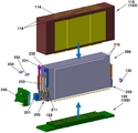
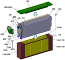
도 1 및 도 2는 본 발명의 실시예에 따른 배터리 모듈을 나타낸 분해 사시도
도 3은 본 발명의 실시예에 따른 배터리 모듈을 나타낸 결합 사시도
도 4는 도 3의 A-A에서 본 단면도1 and 2 are exploded perspective views illustrating a battery module according to an embodiment of the present invention.
3 is a perspective view illustrating a battery module according to an embodiment of the present invention.
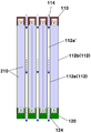
4 is a cross-sectional view taken along line AA of Fig. 3
이하, 첨부한 도면을 참조하여 본 발명의 바람직한 실시예에 대해 본 발명이 속하는 기술분야에서 통상의 지식을 가진 자가 용이하게 실시할 수 있도록 설명하기로 한다. Hereinafter, preferred embodiments of the present invention will be described in detail with reference to the accompanying drawings so that those skilled in the art can easily carry out the present invention.
본 발명에 따른 배터리 모듈은, 배터리 모듈 내부의 가스 배출을 위한 벤팅 구조 및 외부 수분의 유입을 방지하기 위한 실링 구조를 갖는 것으로, 도 1 내지 3에 나타낸 바와 같이, 모듈 하우징(100)과 이 모듈 하우징(100) 내에 수납되는 셀 조립체(200) 및 상기 모듈 하우징(100)의 일측에 설치되는 에어벤트부재(130)를 포함하여 구성된다.The battery module according to the present invention has a venting structure for discharging gas inside the battery module and a sealing structure for preventing inflow of external moisture. As shown in FIGS. 1 to 3, the battery module includes a
모듈 하우징(100)은 셀 조립체(200)를 수용하는 밀폐형의 내부공간을 갖는 상부 하우징(110)과 이 상부 하우징(110)의 하단부에 기밀하게 부착되는 하부 하우징(120)으로 구성되고, 상부 하우징(110)의 성형시 상부 하우징(110)과 일체형으로 형성되는 복수 개의 셀커버(112)를 갖는다.The
상기 셀커버(112)는 상부 하우징(110)의 사출 성형시 인서트 성형 방식을 적용함에 의해 상부 하우징(110)과 일체로 성형되며, 일례로는 알루미늄 소재로 된 셀커버가 사용된다.The
상기 복수 개의 셀커버(112) 중, 상부 하우징(110)의 내부에 위치된 이너 셀커버(112a)는 셀커버(112) 사이에 압입되는 셀(210)의 냉각을 위한 냉각유체가 유동할 수 있는 냉각유로(112a')를 가지며, 상부 하우징(110)의 전후 측벽부에 일체로 형성된 사이드 셀커버(112b)는 냉각유로가 생략된 판상의 구조를 가진다.The
상기 냉각유로(112a')를 갖는 이너 셀커버(112a)는 그 일측 단부가 상부 하우징(110)의 상단면에 형성된 유체입구(114)와 일체로 이어지고 그 타측 단부가 상부 하우징(110)의 하단부 밖으로 돌출되며, 이러한 이너 셀커버(112a)의 타측 단부는 상부 하우징(110)과 하부 하우징(120)의 융착(예를 들어, 레이저, 초음파, 열 등을 이용함) 결합시 하부 하우징(120)에 형성된 유체출구(124)에 기밀하게 삽입된 형태로 조립된다(도 4 참조).One end of the
이때 유체출구(124)에 조립된 이너 셀커버(112a)는 유체출구(124)와의 기밀성을 확보하기 위하여 모듈 하우징(100) 외측에서 실러 등을 도포하는 것이 바람직하다.At this time, the
여기서, 도면부호 122는 유체출구(124)에 삽입된 이너 셀커버(112a)를 지지하기 위한 가이드 리브(122)이다. 즉, 하부 하우징(120)은 그 내측면(상부 하우징(110)과 마주하는 면)에 유체출구(124)에 삽입된 이너 셀커버(112a)의 단부를 지지하기 위한 가이드 리브(122)를 갖는다.Here,
도 1 내지 4에 보이듯, 셀 조립체(200)는 복수 개의 파우치형 배터리 셀(210)이 일렬로 나란하게 배열된 조립 구조를 가지며, 상기 복수 개의 배터리 셀(210)은 상부 하우징(110)의 내부공간에 삽입시 셀커버(112)들 사이에 압입된 형태로 위치되어 면압을 지지받게 되고, 이너 셀커버(112a)의 냉각유로(112a')에 흐르는 냉각유체에 의해 냉각 가능하게 된다.1 to 4, the
즉, 모듈 하우징(100) 내부에 수납된 복수 개의 셀(210)은 서로 이웃한 셀커버(112)에 의해 양측면이 지지되어 일정 면압을 유지하게 되고, 모듈 하우징(100)의 유체입구(114)와 유체출구(124) 사이를 이어주는 셀커버(112)의 냉각유로(112a')에 흐르는 냉각유체에 의해 셀 냉각이 이루어진다.That is, the plurality of
이때 균일한 냉각 성능을 확보하기 위하여, 서로 이웃한 셀커버(112) 사이에는 2개의 셀(210)이 삽입되는 것이 일반적이다.At this time, in order to ensure uniform cooling performance, two
또한 셀 조립체(200)는 복수 개의 셀(210)이 셀탭(233)에 의해 직렬로 연결되고, 상기 복수 개의 셀(210) 중 최외각에 배치된 셀의 단자(211)에는 각각 셀 조립체(200)의 전력(즉, 복수 개의 셀에서 출력되는 전력)을 외부에 전달하기 위한 제1버스바(231)와 제2버스바(232)가 전기적으로 연결된다.The plurality of
상기 제1버스바(231)와 제2버스바(232) 중 어느 하나는 셀 조립체(200)의 음극 단자에 연결되고 다른 하나는 셀 조립체(200)의 양극 단자에 연결된다.One of the
상기 제1버스바(231)와 제2버스바(232)는 모듈 하우징(100)의 일측을 관통하는 제1터미널(234) 및 제2터미널(235)과 각각 전기적으로 연결되며, 이를 위하여 상부 하우징(110)의 일측에는 제1 및 제2터미널이 기밀하게 관통할 수 있는 터미널관통홀(116)이 구비된다.The
제1 및 제2터미널(234,235)은 셀 조립체(200)의 전력을 외부로 공급하기 위한 것으로 그 외주면에 일체형으로 형성된 실링러버(234a,235a)를 가지며, 상기 실링러버(234a,235a)에 의해 상부 하우징(110)의 터미널관통홀(116)을 기밀하게 관통하여 제1 및 제2버스바(231,232)와 연결된다.The first and
여기서, 상기 각 버스바(231,232)와 터미널(234,235)은 서로 체결가능한 구조를 가지며, 예를 들어 제1 및 제2버스바(231,232)는 일측에 너트 형상의 구조가 구비되고 제1 및 제2터미널(234,235)은 그 단부에 볼트 형상의 구조가 구비된다.The
바람직하게, 셀 조립체(200)는 셀 전압 센싱을 위한 전압센싱용 모듈(220)이 구비되며, 상기 전압센싱용 모듈(220)은 최외각에 배치된 셀의 단자(211)에 전기적으로 연결된다.Preferably, the
상기 전압센싱용 모듈(220)은 커넥터(221)를 통해 전압센싱용 퓨즈박스(240)와 전기적으로 연결되고, 상기 커넥터(221)와 전압센싱용 퓨즈박스(240)는 모듈 하우징(100)의 외부에 부착된다.The
이때 모듈 하우징(100)의 기밀성을 확보하기 위하여, 상부 하우징(110)과 하부 하우징(120)의 접합 부위에 전압센싱용 모듈(220)과 커넥터(221) 사이에 연결된 와이어(222)가 관통할 수 있는 홈(미도시) 등의 구조를 형성하고, 상부 하우징(110)과 하부 하우징(120) 사이를 통과하는 상기 와이어(222)와 모듈 하우징(100) 사이에 실러를 도포한다.At this time, a
참고로, 상기 전압센싱용 퓨즈박스(240)는 배터리 모듈의 전력이 외부(예를 들어, 전장부하 등)로 출력되는 것을 선택적으로 차단하기 위한 것으로, 배터리 모듈의 외부에 설치된 제어부(미도시)에서 입력되는 제어신호에 의해 전력 흐름을 차단시킬 수 있게 구성된다.The
그리고, 상부 하우징(110)의 일측에는 모듈 하우징(100)의 내부 가스를 외부로 배출하기 위한 에어벤트부재(130)가 기밀하게 설치된다.An
상기 에어벤트부재(130)로는 모듈 하우징(100)의 내부 가스는 외부로 배출하되 모듈 하우징(100)의 외부 가스가 모듈 하우징(100) 내부로 유입되는 것은 차단할 수 있는 통상적인 단방향 에어벤트가 사용되며, 기밀성을 확보하기 위하여 그 외측에 일체형의 실링러버를 구비하거나 또는 상부 하우징(110)의 에어벤트장착홀(115)과 에어벤트부재(130) 사이에 실러를 도포할 수 있다.The
이러한 에어벤트부재(30)는 셀(210)의 이상 거동 등으로 인해 모듈 하우징(100) 내부에 가스가 발생하여 압력 상승시 외부와의 압력 차이에 의해 에어벤트부재(130)를 통해 모듈 하우징(100) 내부의 가스를 외부로 배출하게 된다.The air vent member 30 generates gas in the module housing 100 due to an abnormal behavior of the
상기의 구성으로 이루어진 본 발명의 배터리 모듈은 모듈 단위로 기밀성을 확보하는 동시에 모듈 하우징 내부에 생성되는 가스를 배출가능하게 구성됨으로써, 외부 수분의 유입을 방지하여 외부 습기에 대한 고전압 절연성능을 확보하고 배터리시스템의 신뢰성 및 안정성을 확보하는 동시에, 파우치형 셀의 배터리 모듈 단위에 대한 가스 벤팅 구조를 구현하여 배터리 모듈 내 발생 가스를 모듈 하우징 외부로 배출 가능하여 가스 벤팅과 관련한 법규 대응이 가능하다.The battery module of the present invention having the above-described structure is configured to ensure airtightness in units of modules and to discharge gas generated inside the module housing, thereby preventing the inflow of external moisture to secure high-voltage insulation performance against external moisture The reliability and stability of the battery system can be ensured and the gas venting structure for the battery module unit of the pouch type cell can be implemented to discharge the generated gas in the battery module to the outside of the module housing.
이상으로 본 발명의 실시예에 대해 상세히 설명하였는바, 본 발명의 권리범위는 상술한 실시예에 한정되지 않으며, 다음의 특허청구범위에서 정의하고 있는 본 발명의 기본 개념을 이용한 당업자의 여러 변형 및 개량 또한 본 발명의 권리범위에 포함된다.
While the present invention has been particularly shown and described with reference to exemplary embodiments thereof, it is to be understood that the scope of the present invention is not limited to the disclosed exemplary embodiments. Modifications are also included in the scope of the present invention.
100 : 모듈 하우징
110 : 상부 하우징
112 : 셀커버
112a : 이너 셀커버
112a' : 냉각유로
112b : 사이드 셀커버
114 : 유체입구
115 : 에어벤트장착홀
116 : 터미널관통홀
120 : 하부 하우징
122 : 가이드 리브
124 : 유체출구
130 : 에어벤트부재
200 : 셀 조립체
210 : 셀
211 : 셀 단자
220 : 전압센싱용 모듈
221 : 커넥터
231 : 제1버스바
232 : 제2버스바
233 : 셀탭
234 : 제1터미널
235 : 제2터미널
240 : 전압센싱용 퓨즈박스100: module housing 110: upper housing
112:
112a ':
114: fluid inlet 115: air vent mounting hole
116: Terminal through hole 120: Lower housing
122: Guide rib 124: Fluid outlet
130: air vent member 200: cell assembly
210: cell 211: cell terminal
220: Voltage sensing module 221: Connector
231: first bus bar 232: second bus bar
233: SELEPH 234: Terminal 1
235: second terminal 240: fuse box for voltage sensing
Claims (6)
상기 셀 조립체를 수용하는 밀폐형의 내부공간을 갖는 상부 하우징과 상기 상부 하우징의 하단부에 기밀하게 부착되는 하부 하우징으로 이루어진 모듈 하우징;
상기 모듈 하우징의 일측에 기밀하게 설치되어 모듈 하우징의 내부 가스를 외부로 배출만 할 수 있는 에어벤트부재;
를 포함하여 구성된 것을 특징으로 하는 배터리 모듈.
A cell assembly comprising a plurality of cells;
A module housing having an upper housing having a closed inner space for accommodating the cell assembly and a lower housing hermetically attached to a lower end of the upper housing;
An air vent member which is hermetically installed at one side of the module housing and can only exhaust the internal gas of the module housing to the outside;
The battery module comprising:
상기 셀 조립체는 서로 연결된 복수 개의 셀에서 출력되는 전력을 외부로 전달하기 위한 제1버스바와 제2버스바가 구비되고, 상기 모듈 하우징의 일측을 관통하는 제1터미널과 제2터미널이 각각 상기 제1버스바 및 제2버스바와 전기적으로 연결가능하게 조립되며, 상기 제1 및 제2터미널은 그 외측에 일체로 형성된 실링러버에 의해 상기 모듈 하우징의 일측을 기밀하게 관통하게 된 것을 특징으로 하는 배터리 모듈.
The method according to claim 1,
Wherein the cell assembly includes a first bus bar and a second bus bar for externally transmitting power output from a plurality of cells connected to each other, and a first terminal and a second terminal passing through one side of the module housing, And the first and second terminals are hermetically passed through one side of the module housing by a sealing rubber integrally formed on the outside of the first and second terminals. .
상기 상부 하우징은 그 내부공간에 삽입된 셀 조립체의 셀 면압을 유지하기 위한 복수 개의 셀커버가 일체로 성형된 것을 특징으로 하는 배터리 모듈.
The method according to claim 1,
Wherein the upper housing is integrally formed with a plurality of cell covers for maintaining the cell surface pressure of the cell assembly inserted in the inner space thereof.
상기 상부 하우징은 그 내부공간에 삽입된 셀 조립체의 셀 면압을 유지하기 위한 복수 개의 셀커버가 일체로 형성되고, 상기 셀커버 중 상부 하우징의 내측에 위치된 셀커버는 셀 냉각용 냉각유체의 유동을 위한 냉각유로를 갖는 것을 특징으로 하는 배터리 모듈.
The method according to claim 1,
A plurality of cell covers for maintaining the cell surface pressure of the cell assembly inserted in the inner space of the upper housing are integrally formed and the cell cover positioned inside the upper housing of the cell covers is formed by a flow of the cooling fluid for cell cooling And a cooling channel for cooling the battery module.
상기 셀커버는 상부 하우징의 하측으로 돌출된 타측 단부가 하부 하우징에 형성된 유체출구에 기밀하게 조립되고, 그 일측 단부가 상부 하우징의 상단면에 형성된 유체입구에 일체로 이어지게 된 것을 특징으로 하는 배터리 모듈.
The method according to claim 3 or 4,
Wherein the cell cover is hermetically assembled to the fluid outlet formed in the lower housing and the other end of the cell cover is integrally connected to the fluid inlet formed on the upper surface of the upper housing. .
상기 하부 하우징은 그 내측면에 유체출구에 삽입된 셀커버의 단부를 지지하기 위한 가이드 리브를 갖는 것을 특징으로 하는 배터리 모듈.
The method of claim 5,
Wherein the lower housing has a guide rib for supporting an end of a cell cover inserted into a fluid outlet at an inner side of the lower housing.
Priority Applications (4)
| Application Number | Priority Date | Filing Date | Title |
|---|---|---|---|
| KR1020150102283A KR20170010531A (en) | 2015-07-20 | 2015-07-20 | Battery module |
| US14/959,965 US10283755B2 (en) | 2015-07-20 | 2015-12-04 | Battery module |
| EP15198396.2A EP3121892A1 (en) | 2015-07-20 | 2015-12-08 | Battery module |
| CN201510962084.1A CN106374063A (en) | 2015-07-20 | 2015-12-21 | Battery module |
Applications Claiming Priority (1)
| Application Number | Priority Date | Filing Date | Title |
|---|---|---|---|
| KR1020150102283A KR20170010531A (en) | 2015-07-20 | 2015-07-20 | Battery module |
Publications (1)
| Publication Number | Publication Date |
|---|---|
| KR20170010531A true KR20170010531A (en) | 2017-02-01 |
Family
ID=54834734
Family Applications (1)
| Application Number | Title | Priority Date | Filing Date |
|---|---|---|---|
| KR1020150102283A KR20170010531A (en) | 2015-07-20 | 2015-07-20 | Battery module |
Country Status (4)
| Country | Link |
|---|---|
| US (1) | US10283755B2 (en) |
| EP (1) | EP3121892A1 (en) |
| KR (1) | KR20170010531A (en) |
| CN (1) | CN106374063A (en) |
Cited By (7)
| Publication number | Priority date | Publication date | Assignee | Title |
|---|---|---|---|---|
| WO2019208922A1 (en) * | 2018-04-25 | 2019-10-31 | 주식회사 엘지화학 | Battery module, battery pack including same battery module, and vehicle including same battery pack |
| KR20190128812A (en) * | 2018-05-09 | 2019-11-19 | 에스케이이노베이션 주식회사 | Bettery module |
| WO2022045619A1 (en) * | 2020-08-26 | 2022-03-03 | 주식회사 엘지에너지솔루션 | Battery module and method of manufacturing same |
| US11462801B2 (en) | 2019-03-06 | 2022-10-04 | Lg Energy Solution, Ltd. | Battery module having structure capable of preventing inflow of air into module when thermal runaway occurs and battery pack including same |
| KR20230092357A (en) | 2021-12-17 | 2023-06-26 | 현대자동차주식회사 | Battery pack for vehicle |
| KR20230106401A (en) | 2022-01-06 | 2023-07-13 | 현대자동차주식회사 | Vehicle battery pack safety structure |
| WO2024019400A1 (en) * | 2022-07-20 | 2024-01-25 | 주식회사 엘지에너지솔루션 | Battery pack and vehicle comprising same |
Families Citing this family (4)
| Publication number | Priority date | Publication date | Assignee | Title |
|---|---|---|---|---|
| KR102371046B1 (en) * | 2016-07-15 | 2022-03-07 | 현대자동차주식회사 | End cell heater for fuel cell |
| CN113644350A (en) * | 2020-04-24 | 2021-11-12 | 比亚迪股份有限公司 | Battery pack and electric vehicle |
| CN111293253B (en) * | 2020-04-24 | 2020-10-23 | 比亚迪股份有限公司 | Battery pack and electric vehicle |
| CN111312964B (en) * | 2020-04-24 | 2022-01-07 | 比亚迪股份有限公司 | Battery pack and electric vehicle |
Citations (1)
| Publication number | Priority date | Publication date | Assignee | Title |
|---|---|---|---|---|
| KR20140085890A (en) | 2012-12-28 | 2014-07-08 | 현대자동차주식회사 | Battery module assembly for high voltage battery pack |
Family Cites Families (13)
| Publication number | Priority date | Publication date | Assignee | Title |
|---|---|---|---|---|
| JP4224186B2 (en) * | 1999-06-10 | 2009-02-12 | パナソニック株式会社 | Collective secondary battery |
| EP1780865B1 (en) * | 2005-10-31 | 2017-02-22 | Black & Decker, Inc. | Thermal management system for a battery pack |
| DE102009000660A1 (en) | 2009-02-06 | 2010-08-12 | Robert Bosch Gmbh | battery module |
| DE102009015686A1 (en) | 2009-03-31 | 2010-10-07 | Li-Tec Battery Gmbh | Battery housing with sealing plate |
| KR101146363B1 (en) | 2010-06-04 | 2012-05-17 | 에스비리모티브 주식회사 | Battery pack |
| DE112012000438T5 (en) | 2011-01-10 | 2013-10-02 | Cobasys, Llc | Flexible battery module for prismatic cells |
| SG175219A1 (en) | 2011-01-24 | 2012-02-28 | Feng Guoan | Power battery pack cooling apparatus |
| KR101469518B1 (en) * | 2011-08-01 | 2014-12-05 | 주식회사 엘지화학 | Battery Module of Improved Stability |
| US9722216B2 (en) | 2012-07-18 | 2017-08-01 | General Electric Company | Energy storage device and method |
| KR101936572B1 (en) | 2012-07-26 | 2019-01-09 | 에스케이이노베이션 주식회사 | Hermetic Battery Module |
| JP2014216248A (en) | 2013-04-26 | 2014-11-17 | 三菱自動車工業株式会社 | Battery case |
| KR101520902B1 (en) | 2013-04-29 | 2015-05-15 | 주식회사 엘지화학 | Case for vehicle's battery pack |
| US9912019B2 (en) | 2013-05-20 | 2018-03-06 | Hamilton Sundstrand Corporation | Thermal management of electrical storage devices by coolant pool |
-
2015
- 2015-07-20 KR KR1020150102283A patent/KR20170010531A/en active Search and Examination
- 2015-12-04 US US14/959,965 patent/US10283755B2/en active Active
- 2015-12-08 EP EP15198396.2A patent/EP3121892A1/en not_active Withdrawn
- 2015-12-21 CN CN201510962084.1A patent/CN106374063A/en active Pending
Patent Citations (1)
| Publication number | Priority date | Publication date | Assignee | Title |
|---|---|---|---|---|
| KR20140085890A (en) | 2012-12-28 | 2014-07-08 | 현대자동차주식회사 | Battery module assembly for high voltage battery pack |
Cited By (8)
| Publication number | Priority date | Publication date | Assignee | Title |
|---|---|---|---|---|
| WO2019208922A1 (en) * | 2018-04-25 | 2019-10-31 | 주식회사 엘지화학 | Battery module, battery pack including same battery module, and vehicle including same battery pack |
| US11764425B2 (en) | 2018-04-25 | 2023-09-19 | Lg Energy Solution, Ltd. | Battery module, battery pack including same battery module, and vehicle including same battery pack |
| KR20190128812A (en) * | 2018-05-09 | 2019-11-19 | 에스케이이노베이션 주식회사 | Bettery module |
| US11462801B2 (en) | 2019-03-06 | 2022-10-04 | Lg Energy Solution, Ltd. | Battery module having structure capable of preventing inflow of air into module when thermal runaway occurs and battery pack including same |
| WO2022045619A1 (en) * | 2020-08-26 | 2022-03-03 | 주식회사 엘지에너지솔루션 | Battery module and method of manufacturing same |
| KR20230092357A (en) | 2021-12-17 | 2023-06-26 | 현대자동차주식회사 | Battery pack for vehicle |
| KR20230106401A (en) | 2022-01-06 | 2023-07-13 | 현대자동차주식회사 | Vehicle battery pack safety structure |
| WO2024019400A1 (en) * | 2022-07-20 | 2024-01-25 | 주식회사 엘지에너지솔루션 | Battery pack and vehicle comprising same |
Also Published As
| Publication number | Publication date |
|---|---|
| EP3121892A1 (en) | 2017-01-25 |
| US20170025664A1 (en) | 2017-01-26 |
| US10283755B2 (en) | 2019-05-07 |
| CN106374063A (en) | 2017-02-01 |
Similar Documents
| Publication | Publication Date | Title |
|---|---|---|
| KR20170010531A (en) | Battery module | |
| US10411233B2 (en) | Secondary battery cartridge and battery module comprising same | |
| US9306251B2 (en) | Battery pack | |
| US20170373287A1 (en) | Battery pack | |
| CN106471643B (en) | For accommodating the shell of multiple battery cells with the cooling device being integrated in shell | |
| KR101174045B1 (en) | Battery pack and battery pack assembly having the same | |
| JP6805724B2 (en) | Battery pack | |
| CN108493364B (en) | Battery module and battery pack | |
| KR102017231B1 (en) | Battery Module Having Improved Sealing Characteristics of Cooling Duct | |
| KR102433361B1 (en) | Battery module and battery pack including the same | |
| CN107004922B (en) | Cooling plate for battery unit as assembly plate | |
| JP6627682B2 (en) | Battery pack | |
| JP6256439B2 (en) | Battery pack | |
| US8415040B2 (en) | Secondary battery module containing temperature sensor and sealing member surrounding conductive wire of temperature sensor | |
| KR20160008447A (en) | A battery package | |
| CN113451695A (en) | Battery module and electric vehicle | |
| JP2017054866A (en) | Power storage module | |
| US20230051278A1 (en) | Battery module, and battery pack and automobile including same | |
| US20150064527A1 (en) | Energy store covering module and method for assemblying an energy store covering module | |
| JP6129329B2 (en) | Power storage device | |
| KR20220169513A (en) | Battery module for eco-friendly vehicle | |
| KR101775686B1 (en) | Battery Pack | |
| JP7051552B2 (en) | Batteries assembled | |
| CN220253415U (en) | Battery module and battery pack including the same | |
| JP6563765B2 (en) | Battery pack |
Legal Events
| Date | Code | Title | Description |
|---|---|---|---|
| A201 | Request for examination |