KR20170010455A - Lamp for vehicle - Google Patents
Lamp for vehicle Download PDFInfo
- Publication number
- KR20170010455A KR20170010455A KR1020150099016A KR20150099016A KR20170010455A KR 20170010455 A KR20170010455 A KR 20170010455A KR 1020150099016 A KR1020150099016 A KR 1020150099016A KR 20150099016 A KR20150099016 A KR 20150099016A KR 20170010455 A KR20170010455 A KR 20170010455A
- Authority
- KR
- South Korea
- Prior art keywords
- hollow portion
- light source
- light
- optic
- optical body
- Prior art date
Links
Images


Classifications
-
- F21S48/22—
-
- F21S48/215—
-
- F21S48/2212—
-
- F21S48/23—
-
- F—MECHANICAL ENGINEERING; LIGHTING; HEATING; WEAPONS; BLASTING
- F21—LIGHTING
- F21V—FUNCTIONAL FEATURES OR DETAILS OF LIGHTING DEVICES OR SYSTEMS THEREOF; STRUCTURAL COMBINATIONS OF LIGHTING DEVICES WITH OTHER ARTICLES, NOT OTHERWISE PROVIDED FOR
- F21V5/00—Refractors for light sources
- F21V5/04—Refractors for light sources of lens shape
- F21V5/045—Refractors for light sources of lens shape the lens having discontinuous faces, e.g. Fresnel lenses
-
- F21W2101/14—
-
- F—MECHANICAL ENGINEERING; LIGHTING; HEATING; WEAPONS; BLASTING
- F21—LIGHTING
- F21Y—INDEXING SCHEME ASSOCIATED WITH SUBCLASSES F21K, F21L, F21S and F21V, RELATING TO THE FORM OR THE KIND OF THE LIGHT SOURCES OR OF THE COLOUR OF THE LIGHT EMITTED
- F21Y2101/00—Point-like light sources
-
- F—MECHANICAL ENGINEERING; LIGHTING; HEATING; WEAPONS; BLASTING
- F21—LIGHTING
- F21Y—INDEXING SCHEME ASSOCIATED WITH SUBCLASSES F21K, F21L, F21S and F21V, RELATING TO THE FORM OR THE KIND OF THE LIGHT SOURCES OR OF THE COLOUR OF THE LIGHT EMITTED
- F21Y2115/00—Light-generating elements of semiconductor light sources
- F21Y2115/30—Semiconductor lasers
Abstract
Description
본 발명은 옵틱 본체 내부에 중공부를 구비하고 옵틱 본체의 외면을 기능이 다른 다면으로 구성하여 차량용 배광 법규를 만족시키면서 선 또는 면광원 이미지를 구현할 수 있도록 한 차량용 램프에 관한 것이다.The present invention relates to a vehicle lamp having a hollow portion inside an optical body and having an outer surface of an optic body as a multifunctional surface having different functions, thereby realizing a line or a plane light source image while satisfying a light distribution rule for a vehicle.
일반적으로 차량에는 야간 주행시 차량 주변에 위치한 대상물을 확인하기 위한 조명 기능을 하는 램프 및 다른 차량이나 기타 도로 이용자에게 자기 차량의 주행 상태를 알리기 위한 신호 기능 등 다양한 기능을 수행하는 차량용 램프들이 구비되어 있다. 구체적으로 전조등 및 안개등 등은 조명 기능을 목적으로 하고, 방향 지시등, 미등, 제동등, 사이드 마커(Side Marker)등은 시그널 램프로서 신호 기능을 목적으로 한다. 그러나 종래의 시그널 램프 본체는 사출물의 크기 및 두께 증가로 인해 성형성이 좋지 않고 생산 시간이 오래 걸리며, 수축 변형이 발생하는 단점이 있다.Generally, the vehicle is equipped with a lamp that performs a lighting function for identifying an object located in the vicinity of the vehicle when driving at night, and a vehicle lamp that performs various functions such as a signal function for notifying other vehicles or other road users of the traveling state of the vehicle . Specifically, headlights and fog lights are aimed at lighting functions, and turn signal lamps, taillights, brake lights, side markers and the like are used as signal lamps as signal lamps. However, the conventional signal lamp main body has a disadvantage in that the moldability is poor due to the increase in size and thickness of the injection molded product, the production time is long, and shrinkage deformation occurs.
일례로서, 대한민국 실용신안등록 제0463049호는 "차량용 시그널 램프"를 개시한다.As an example, Korean Utility Model Registration No. 0463049 discloses a "vehicle signal lamp ".
전술한 문제를 해결하기 위하여, 본 발명의 실시예는 옵틱 본체 내부에 중공부를 구비하고 옵틱 본체의 외면을 기능이 다른 다면으로 구성하여 차량용 배광 법규를 만족시키면서 선 또는 면광원 이미지를 구현할 수 있도록 한 차량용 램프를 제공하고자 한다.In order to solve the above-described problems, an embodiment of the present invention is to provide an optical system having a hollow portion inside an optical body, and an outer surface of the optical body being formed of a multi-functional surface having different functions, Vehicle lamps.
전술한 목적을 이루기 위해 본 발명의 실시예에 따른 차량용 램프는, 광조사를 위한 광원; 및 내부에 중공부가 구비되며 상기 중공부에는 중공부의 입구 쪽에 구비되는 상기 광원으로부터 광조사가 이루어지고, 상기 중공부로 조사된 광원의 광을 반사 또는 투과할 수 있도록 외면이 다면으로 이루어지는 옵틱 본체; 를 포함할 수 있다.According to an aspect of the present invention, there is provided a lamp for a vehicle comprising: a light source for light irradiation; And a hollow portion inside the hollow portion, wherein the hollow portion is irradiated with light from the light source provided at the entrance side of the hollow portion, and the outer surface of the hollow portion has a multi-faceted surface so as to be able to reflect or transmit light from the light source. . ≪ / RTI >
또한, 상기 광원은 LED 또는 레이저일 수 있다.In addition, the light source may be an LED or a laser.
또한, 상기 광원과 옵틱 본체를 포함하는 옵틱의 길이는 20 mm 내지 50 mm 일 수 있다.In addition, the length of the optic including the light source and the optical body may be 20 mm to 50 mm.
또한, 상기 옵틱 본체의 중공부 내부에는 옵틱 본체 내부의 측면을 구성하는 측벽면과 옵틱 본체 내부 안쪽 전방에 내부 렌즈면이 구비될 수 있다.Also, inside the hollow portion of the optic body, a sidewall surface constituting a side surface inside the optic body and an inner lens surface in front of the inside of the optic body may be provided.
또한, 상기 측벽면은 전방에서 후방으로 갈수록 폭이 넓어질 수 있다.Further, the sidewall surface may have a wider width from the front to the rear.
또한, 상기 측벽면과 옵틱 본체의 중심축이 이루는 각도는 1도일 수 있다.Further, an angle between the sidewall surface and the central axis of the optic body may be 1 degree.
또한, 상기 내부 렌즈면은 구면렌즈, 비구면렌즈 및 프리넬 렌즈 중 선택되는 어느 하나 또는 이들 렌즈들의 배열로 구성될 수 있다.In addition, the inner lens surface may be composed of any one selected from a spherical lens, an aspherical lens, and a Fresnel lens or an array of these lenses.
또한, 상기 내측면은 경사를 이루면서 표면이 평면 또는 경사를 이루면서 표면이 곡면일 수 있다.In addition, the inner surface may be inclined and the surface may be flat or inclined while the surface may be curved.
또한, 상기 내부 렌즈면의 단면 길이는 7 mm 이상일 수 있다.The cross-sectional length of the inner lens surface may be 7 mm or more.
또한, 상기 옵틱 본체의 외면 전체 또는 특정 부위는 부식 처리될 수 있다.Further, the entire outer surface or a specific portion of the optic body may be subjected to a corrosion treatment.
또한, 상기 옵틱 본체의 외면은 상기 옵틱 본체 외면의 부분면으로서, 상기 중공부로 조사된 광원의 광을 반사하는 전반사면; 및 상기 전반사면에 이웃하도록 옵틱 본체의 외면에 구비되는 것으로서, 상기 중공부로 조사된 광원의 광을 반사하거나 투과시키는 반사투과면; 을 포함할 수 있다.In addition, the outer surface of the optical body may be a partial surface of the outer surface of the optical body, a total reflection surface reflecting the light of the light source irradiated to the hollow portion, And a reflective transmitting surface provided on an outer surface of the optical body so as to be adjacent to the total reflection surface, the reflective transmitting surface reflecting or transmitting light of the light source irradiated to the hollow portion; . ≪ / RTI >
또한, 상기 전반사면은 상기 옵틱 본체의 외측 후방 상, 하면 부위에 구비될 수 있다.In addition, the total reflection surface may be provided on an outer rear side and a bottom side of the optical body.
또한, 상기 전반사면은 상기 후방으로 갈수록 하향으로 기울어지는 경사면일 수 있다.In addition, the total reflection surface may be an inclined surface inclined downward toward the rear.
또한, 상기 전반사면과 옵틱 본체의 중심축이 이루는 각도는 35도 내지 55도일 수 있다.The angle formed by the total reflection surface and the central axis of the optic body may be between 35 degrees and 55 degrees.
또한, 상기 반사투과면은 세레이션 형태로 형성될 수 있다.In addition, the reflection transmitting surface may be formed in a serration shape.
또한, 상기 반사투과면은 상기 옵틱 본체의 상, 하면 중 어느 한쪽에 구비되거나 또는 옵틱 본체의 전반사면과 정면을 제외한 옵틱 본체의 외면 전체 면에 구비될 수 있다.The reflective transmitting surface may be provided on one of the upper and lower surfaces of the optical body, or may be provided on the entire outer surface of the optical body excluding the front and the total reflection surfaces of the optical body.
또한, 상기 중공부의 길이는 상기 옵틱 본체 전방의 벽체 두께를 제외하고 옵틱 본체 길이에서 대부분을 차지할 수 있다.Further, the length of the hollow portion may occupy most of the length of the optical body, except for the wall thickness in front of the optical body.
또한, 상기 중공부의 길이는 광이 방출되는 옵틱 본체 전방의 벽체 두께보다 더 길 수 있다.In addition, the length of the hollow portion may be longer than the thickness of the wall in front of the optic body from which light is emitted.
또한, 광조사를 위한 광원; 및 내부에 중공부가 구비되며 상기 중공부에는 중공부의 입구 쪽에 구비되는 상기 광원으로부터 광조사가 이루어지고, 상기 중공부로 조사된 광원의 광을 반사 또는 투과할 수 있도록 외면이 다면으로 이루어지는 옵틱 본체; 를 포함하는 램프가 복수로 구비될 수 있다.A light source for light irradiation; And a hollow portion inside the hollow portion, wherein the hollow portion is irradiated with light from the light source provided at the entrance side of the hollow portion, and the outer surface of the hollow portion has a multi-faceted surface so as to be able to reflect or transmit light from the light source. A plurality of lamps may be provided.
또한, 상기 복수의 옵틱 본체는 일체형 사출물일 수 있다.In addition, the plurality of optic bodies may be an integral type.
본 발명의 실시예에 따른 차량용 램프에 의하면, 옵틱 본체 내부에 중공부를 구비하고 옵틱 본체의 외면을 기능이 다른 다면으로 구성하여 차량용 배광 법규를 만족시키면서 선 또는 면광원 이미지를 구현할 수 있다.According to the vehicle lamp of the present invention, a hollow portion is provided in the optic body, and the outer surface of the optic body is configured as a multifunctional body having different functions, thereby realizing a line or planar light source image while satisfying the vehicular light distribution law.
또한, 옵틱 본체를 중공 형태로 설계함으로써 사출 성형성을 향상시키고 중량을 절감할 수 있다.Further, by designing the optic body in a hollow shape, the injection moldability can be improved and the weight can be saved.
또한, 옵틱 본체의 구조적인 특성에 의해 새로운 형태의 점등 이미지를 구현할 수 있다.In addition, a new type of lit image can be implemented by the structural characteristics of the optical body.
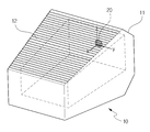
도 1은 본 발명의 바람직한 일 실시예에 따른 사시도이다.
도 2는 본 발명의 바람직한 일 실시예에 따른 측단면도이다.
도 3은 본 발명의 바람직한 일 실시예에 따른 실물사진이다.
도 4는 본 발명의 다른 실시예에 따른 사시도이다.
도 5는 본 발명의 다른 실시예에 따른 평면도이다.1 is a perspective view of a preferred embodiment of the present invention.
2 is a side cross-sectional view according to one preferred embodiment of the present invention.
3 is a photograph of a real object according to a preferred embodiment of the present invention.
4 is a perspective view of another embodiment of the present invention.
5 is a plan view according to another embodiment of the present invention.
이하, 본 발명의 바람직한 실시예를 첨부된 도면들을 참조하여 상세히 설명한다. 우선 각 도면의 구성 요소들에 참조 부호를 부가함에 있어서, 동일한 구성 요소들에 대해서는 비록 다른 도면상에 표시되더라도 가능한 한 동일한 부호를 가지도록 하고 있음에 유의해야 한다. 또한, 이하에서 본 발명의 바람직한 실시예를 설명할 것이나, 본 발명의 기술적 사상은 이에 한정하거나 제한되지 않고 당업자에 의해 변형되어 다양하게 실시될 수 있음은 물론이다.Hereinafter, preferred embodiments of the present invention will be described in detail with reference to the accompanying drawings. In the drawings, the same reference numerals are used to designate the same or similar components throughout the drawings. In addition, the preferred embodiments of the present invention will be described below, but it is needless to say that the technical idea of the present invention is not limited thereto and can be variously modified by those skilled in the art.
먼저 본 발명의 실시예에 따른 차량용 램프의 구성을 설명한다.First, the configuration of a vehicle lamp according to an embodiment of the present invention will be described.
도 1 내지 3에 도시된 바와 같이 본 발명의 실시예에 따른 차량용 램프는 광조사를 위한 광원(20) 및 광원(20)의 광조사가 이루어지는 옵틱 본체(10)을 포함한다.1 to 3, a vehicle lamp according to an embodiment of the present invention includes a
구체적으로 광원(20)은 LED(발광 다이오드, light emitting diode) 또는 레이저(laser)일 수 있다. 광원(20)은 복수로 구성될 수 있으나 단수로 구성하는 것이 바람직하다. 광원(20)은 옵틱 본체(10)의 중공부(13) 입구 쪽에 위치되어 중공부(13) 내부로 광을 조사한다. 광원(20)과 옵틱 본체(10)를 포함하는 옵틱의 길이(L)는 20 mm 내지 50 mm 인 것이 바람직하다. 옵틱의 길이(L)는 광원(20)에서 옵틱 본체(10)의 정면까지의 길이이다.Specifically, the
옵틱 본체(10)는 내부에 구비되는 중공부(13) 및 중공부(13)로 조사되는 광원(20)의 광을 반사 또는 투과시키는 다면으로 이루어지는 외면을 포함한다. 중공부(13)에는 광원(20)의 광이 조사된다. 옵틱 본체(10)의 중공부(13) 내부에는 옵틱 본체(10)의 내부 측면을 구성하는 측벽면(131)이 구비되고 옵틱 본체(10)의 내부 안쪽에는 내부 렌즈면(132)이 구비된다.The
중공부의 길이(T)는 상기 옵틱 본체 전방의 벽체 두께(t)를 제외하고 옵틱 본체 길이에서 대부분을 차지하는 것이 바람직하다. 또한, 중공부의 길이(T)는 광이 방출되는 옵틱 본체 전방의 벽체 두께(t)보다 더 긴 것이 바람직하다.It is preferable that the length T of the hollow portion occupies most of the length of the optical body except for the wall thickness t in front of the optical body. It is also preferable that the length T of the hollow portion is longer than the wall thickness t in front of the optic body from which light is emitted.
측벽면(131)은 옵틱 본체(10) 내부의 상하 벽면 또는 입구와 정면을 제외한 상하좌우 벽면일 수 있다. 측벽면(131)은 중공부(13)의 전방에서 후방으로 갈수록 폭이 넓어지는 경사면으로 형성된다. 측벽면(131)과 옵틱 본체(10)의 중심축(14, X축 방향)이 이루는 각도(θ2)는 1도인 것이 바람직하다. 측벽면(131)은 후방으로 갈수록 폭이 점점 넓어지는 경사를 이루면서 표면이 평평한 평면일 수 있다. 측벽면(131)은 후방으로 갈수록 폭이 점점 넓어지는 경사를 이루면서 곡면일 수 있다.The
내부 렌즈면(132)은 옵틱 본체(10) 내부 안쪽 전방에 구비된다. 내부 렌즈면(132)은 구면렌즈, 비구면렌즈 및 프리넬 렌즈 (Fresnel lens) 중 선택되는 어느 하나로 구성될 수 있다. 내부 렌즈면(132)은 구면렌즈, 비구면렌즈 및 프리넬 렌즈의 조합으로 구성될 수 있다. 내부 렌즈면(132)은 동종의 렌즈들의 배열 또는 다른 이종 이상의 렌즈들의 배열로 구성될 수도 있다.The
내부 렌즈면(132)의 단면 길이(l)는 7 mm 이상인 것이 바람직하다. 내부 렌즈면(132)은 원형 또는 사각일 수 있다. 예컨대 내부 렌즈면(132)이 원형일 경우 단면 길이(1)는 지름으로서 지름이 7 mm 이상이어야 한다. 내부 렌즈면(132)이 사각일 경우 단면 길이(l)는 최소 단면의 길이로서, 즉 사각의 세로 단면 또는 가로 단면 길이 중 더 작은 쪽의 단면 길이가 7 mm 이상이어야 한다.The cross-sectional length l of the
옵틱 본체(10)의 외면은 광원(20)에서 조사되는 광의 굴절률을 높이기 위해 부식 처리를 할 수 있다. 옵틱 본체(10)의 외면 전체 또는 외면 특정 부위만을 부식 처리할 수 있다. 반사투과면(12)만 부식 처리를 할 수도 있다.The outer surface of the
옵틱 본체(10)의 외면은 전반사면(11)과 반사투과면(12) 등의 다면으로 구성된다. 전반사면(11)은 옵틱 본체(10) 외면 후방 상, 하면에 부위에 구비된다. 전반사면(11)은 후방으로 갈수록 하향으로 기울어지는 경사면으로 구성된다. 상, 하로 구성되는 전반사면(11)은 대칭 형성되는 것이 바람직하다. 전반사면(11)과 옵틱 본체(10)의 중심축(14)이 이루는 각도(θ1)는 35도 내지 55도(45도±10도)인 것이 바람직하다.The outer surface of the
반사투과면(12)은 전반사면(11)과 이웃하도록 옵틱 본체(10)의 외면에 구비된다. 반사투과면(12)은 옵틱 본체(10)의 외면 상, 하면 중 어느 한쪽에 구비될 수 있다. 반사투과면(12)은 옵틱 본체(10)의 전반사면(11)과 정면을 제외한 옵틱 본체(10) 외면 전체에 구비될 수 있다. 반사투과면(12)은 광원(20) 광의 반사와 투과가 동시에 이루어질 수 있는 세레이션(serration) 형태로 구성될 수 있다.The
한편, 다른 예로서 위에서 설명한 광조사를 위한 광원(20) 및 내부에 중공부(13)가 구비되며 중공부(13)에는 중공부(13)의 입구 쪽에 구비되는 광원(20)으로부터 광조사가 이루어지고 중공부(13)로 조사된 광원(20)의 광을 반사 또는 투과할 수 있도록 외면이 다면으로 이루어지는 옵틱 본체(10)를 포함하는 램프가 도 4, 5와 같이 복수로 구비된다. 이때 복수로 구비되는 옵틱 본체(10)는 일체형 사출물로 인 것이 바람직하다.As another example, the
이하 본 발명의 실시예에 따른 차량용 램프의 작용을 설명한다.Hereinafter, the operation of the vehicle lamp according to the embodiment of the present invention will be described.
도 2, 3에 도시된 바와 같이 광원(20)으로부터 조사되는 광은 약 0도 ~ 최대 30도로 방사된다. 중공부(13)의 입구에 구비되는 광원(20)의 광은 옵틱 본체(10)의 중공부(13)로 조사된다. 중공부(13)로 조사된 광원(20)의 광은 옵틱 본체(10)의 내부에 조사되면서 반사 투과된다.As shown in FIGS. 2 and 3, the light emitted from the
구체적으로 광원(20)의 광은 내부 렌즈면(132)을 통과하며, 해당 면을 통해 집광 또는 직광되어 배광 법규를 만족할 수 있다. 옵틱 본체(10)의 내부 측벽면(131)을 투과 굴절되어 전반사면(11)에 도달하는 광원(20)의 광은 전반사되어 옵틱 방향대비 약 0도에서 15도 범위 내에서 진행한다.Specifically, the light from the
옵틱 본체(10)의 내부 측벽면(131)을 투과 굴절하여 옵틱 본체(10)의 반사투과면(12)에 도달하는 광원(20)의 광은 도 2의 화살표와 같이 투과 굴절되거나 전반사된다.The light of the
살펴본 바와 같이 본 발명의 실시예에 따른 차량용 램프는, 단수의 광원으로부터 조사되는 광을 통해 옵틱 본체의 내, 외면의 다수의 면을 조광하여 일부 면을 통해 배광 법규를 만족시키는 한편 그 외의 면을 통해 선 또는 면광원 이미지 구현할 수 있다.As described above, a vehicle lamp according to an embodiment of the present invention illuminates a plurality of surfaces of the inner and outer surfaces of an optic body through light emitted from a single light source to satisfy a light distribution rule through a partial surface, You can implement a line or surface light source image through.
또한, 광원 앞에 별도의 프라이머리 옵틱(Primary optic) 또는 반사면을 사용하지 않고, 속이 비어 있는 렌즈 형상으로 사출 성형된 옵틱 본체를 사용함으로써, 램프의 부품수 및 조립 공수를 줄이고 옵틱 본체의 사출 성형성 향상 및 옵틱 본체에 중공부를 둠으로써 중량을 절감할 수 있다. 또한, 옵틱 본체의 구조적인 특성에 의해 광학 효율 향상은 물론 새로운 형태의 점등 이미지를 구현함으로써 소비자들에게 기존과 차별화된 차량용 램프를 제공할 수 있다.In addition, by using an optic body injection-molded in a hollow lens shape without using a separate primary optic or reflecting surface in front of the light source, it is possible to reduce the number of components and assembly number of the lamp, The weight can be saved by improving the properties and placing the hollow part in the optic body. In addition, due to the structural characteristics of the optical body, it is possible to provide differentiated vehicle lamps to consumers by implementing new types of lit images as well as optical efficiency improvement.
이상의 설명은 본 발명의 기술 사상을 예시적으로 설명한 것에 불과한 것으로서, 본 발명이 속하는 기술 분야에서 통상의 지식을 가진 자라면 본 발명의 본질적인 특성에서 벗어나지 않는 범위 내에서 다양한 수정, 변경 및 치환이 가능할 것이다. 따라서, 본 발명에 개시된 실시예 및 첨부된 도면들은 본 발명의 기술 사상을 한정하기 위한 것이 아니라 설명하기 위한 것이고, 이러한 실시예 및 첨부된 도면에 의하여 본 발명의 기술 사상의 범위가 한정되는 것은 아니다. 본 발명의 보호 범위는 아래의 청구범위에 의하여 해석되어야 하며, 그와 동등한 범위 내에 있는 모든 기술 사상은 본 발명의 권리범위에 포함되는 것으로 해석되어야 할 것이다.It will be apparent to those skilled in the art that various modifications, substitutions and substitutions are possible, without departing from the scope and spirit of the invention as disclosed in the accompanying claims. will be. Therefore, the embodiments disclosed in the present invention and the accompanying drawings are intended to illustrate and not to limit the technical spirit of the present invention, and the scope of the technical idea of the present invention is not limited by these embodiments and the accompanying drawings . The scope of protection of the present invention should be construed according to the following claims, and all technical ideas within the scope of equivalents should be construed as falling within the scope of the present invention.
10:옵틱 본체 11:전반사면
12:반사투과면 13:중공부
14:중심축 20:광원
131:측벽면 132:내부 렌즈면
L:옵틱의 길이 l:단면 길이
T:중공부의 길이 t:옵틱 본체 전방의 벽체 두께
θ1:각도 θ2:각도10: Optical body 11:
12: reflection transmitting surface 13: hollow portion
14: central axis 20: light source
131: side wall surface 132: inner lens surface
L: length of optic l: section length
T: length of the hollow part t: wall thickness in front of the optical body
θ 1 : angle θ 2 : angle
Claims (20)
내부에 중공부가 구비되며 상기 중공부에는 중공부의 입구 쪽에 구비되는 상기 광원으로부터 광조사가 이루어지고, 상기 중공부로 조사된 광원의 광을 반사 또는 투과할 수 있도록 외면이 다면으로 이루어지는 옵틱 본체;
를 포함하는 차량용 램프.
A light source for light irradiation; And
An optical body having a hollow portion inside and having an outer surface formed in a multifaceted surface so that the hollow portion is irradiated with light from the light source provided at the entrance side of the hollow portion and can reflect or transmit light from the light source irradiated to the hollow portion;
.
상기 광원은,
LED 또는 레이저인 것을 특징으로 하는 차량용 램프.
The method according to claim 1,
The light source includes:
LED or a laser.
상기 광원과 옵틱 본체를 포함하는 옵틱의 길이는 20 mm 내지 50 mm 인 것을 특징으로 하는 차량용 램프.
The method according to claim 1,
Wherein the length of the optic including the light source and the optic body is 20 mm to 50 mm.
상기 옵틱 본체의 중공부 내부에는,
옵틱 본체 내부의 측면을 구성하는 측벽면과 옵틱 본체 내부 안쪽 전방에 내부 렌즈면이 구비되는 것을 특징으로 하는 차량용 램프.
The method according to claim 1,
Inside the hollow portion of the optic body,
And an inner lens surface is provided on the inner side of the inner side of the inner side of the optical body and the side wall surface constituting the side surface of the inner side of the optical body.
상기 측벽면은 전방에서 후방으로 갈수록 폭이 넓어지는 것을 특징으로 하는 차량용 램프.
The method of claim 4,
Wherein the sidewall surface has a width wider from the front to the rear.
상기 측벽면과 옵틱 본체의 중심축이 이루는 각도는 1도인 것을 특징으로 차량용 램프.
The method of claim 4,
Wherein an angle formed by the side wall surface and a center axis of the optical body is 1 deg.
상기 내부 렌즈면은,
구면렌즈, 비구면렌즈 및 프리넬 렌즈 중 선택되는 어느 하나 또는 이들 렌즈들의 배열로 구성되는 것을 특징으로 하는 차량용 램프.
The method of claim 4,
Wherein the inner lens surface
A spherical lens, an aspherical lens, and a Fresnel lens, or an array of these lenses.
상기 내측면은,
경사를 이루면서 표면이 평면 또는 경사를 이루면서 표면이 곡면인 것을 특징으로 하는 차량용 램프.
The method of claim 4,
The inner surface
Characterized in that the surface is curved in a plane or oblique shape while being inclined.
상기 내부 렌즈면의 단면 길이는,
7 mm 이상인 것을 특징으로 하는 차량용 램프.
The method of claim 4,
Wherein the inner lens surface has a cross-
7 mm or more.
상기 옵틱 본체의 외면 전체 또는 특정 부위는 부식 처리되는 것을 특징으로 하는 차량용 램프.
The method according to claim 1,
Wherein the entire outer surface or a specific portion of the optic body is subjected to a corrosion treatment.
상기 옵틱 본체의 외면은,
상기 옵틱 본체 외면의 부분면으로서, 상기 중공부로 조사된 광원의 광을 반사하는 전반사면; 및
상기 전반사면에 이웃하도록 옵틱 본체의 외면에 구비되는 것으로서, 상기 중공부로 조사된 광원의 광을 반사하거나 투과시키는 반사투과면;
을 포함하는 차량용 램프.
The method according to claim 1,
Wherein an outer surface of the optic body is formed,
A partial reflecting surface of the outer surface of the optical body, the reflecting surface reflecting the light of the light source irradiated to the hollow portion; And
A reflection transmitting surface provided on an outer surface of the optical body so as to be adjacent to the total reflection surface and reflecting or transmitting light of the light source irradiated to the hollow portion;
.
상기 전반사면은,
상기 옵틱 본체의 외측 후방 상, 하면 부위에 구비되는 것을 특징으로 하는 차량용 램프.
The method of claim 11,
Wherein the total reflection surface comprises:
And an outer rear upper and lower surface portions of the optical body.
상기 전반사면은,
상기 후방으로 갈수록 하향으로 기울어지는 경사면인 것을 특징으로 하는 차량용 램프.
The method of claim 11,
Wherein the total reflection surface comprises:
And the inclined surface inclined downward toward the rear.
상기 전반사면과 옵틱 본체의 중심축이 이루는 각도는 35도 내지 55도인 것을 특징으로 하는 차량용 램프.
The method of claim 11,
Wherein an angle formed by the total reflection surface and a center axis of the optical body is in the range of 35 to 55 degrees.
상기 반사투과면은,
세레이션 형태로 형성되는 것을 특징으로 하는 차량용 램프.
The method of claim 11,
Wherein the reflective-
Wherein the lamp is formed in a serration shape.
상기 반사투과면은,
상기 옵틱 본체의 상, 하면 중 어느 한쪽에 구비되거나 또는 옵틱 본체의 전반사면과 정면을 제외한 옵틱 본체의 외면 전체 면에 구비되는 것을 특징으로 하는 차량용 램프.
The method of claim 11,
Wherein the reflective-
Wherein the optical system is provided on one of the upper and lower surfaces of the optic body, or on the entire outer surface of the optic body excluding the frontal plane and the frontal plane of the optical body.
상기 중공부의 길이는,
상기 옵틱 본체 전방의 벽체 두께를 제외하고 옵틱 본체 길이에서 대부분을 차지하는 것을 특징으로 하는 차량용 램프.
The method according to claim 1,
The length of the hollow portion
Characterized in that it occupies most of the length of the optic body except for the wall thickness in front of the optic body.
상기 중공부의 길이는,
광이 방출되는 옵틱 본체 전방의 벽체 두께보다 더 긴 것을 특징으로 하는 차량용 램프.
The method according to claim 1,
The length of the hollow portion
Is longer than the wall thickness in front of the optic body from which light is emitted.
A light source for light irradiation; And a hollow portion inside the hollow portion, wherein the hollow portion is irradiated with light from the light source provided at the entrance side of the hollow portion, and the outer surface of the hollow portion has a multi-faceted surface so as to be able to reflect or transmit light from the light source. And a plurality of lamps including a plurality of lamps.
상기 복수의 옵틱 본체는,
일체형 사출물인 것을 특징으로 하는 차량용 램프.The method of claim 19,
Wherein the plurality of optic bodies comprise:
Wherein the lamp is an integral type injection molded article.
Priority Applications (1)
| Application Number | Priority Date | Filing Date | Title |
|---|---|---|---|
| KR1020150099016A KR102396899B1 (en) | 2015-07-13 | 2015-07-13 | Lamp for vehicle |
Applications Claiming Priority (1)
| Application Number | Priority Date | Filing Date | Title |
|---|---|---|---|
| KR1020150099016A KR102396899B1 (en) | 2015-07-13 | 2015-07-13 | Lamp for vehicle |
Publications (2)
| Publication Number | Publication Date |
|---|---|
| KR20170010455A true KR20170010455A (en) | 2017-02-01 |
| KR102396899B1 KR102396899B1 (en) | 2022-05-13 |
Family
ID=58109220
Family Applications (1)
| Application Number | Title | Priority Date | Filing Date |
|---|---|---|---|
| KR1020150099016A KR102396899B1 (en) | 2015-07-13 | 2015-07-13 | Lamp for vehicle |
Country Status (1)
| Country | Link |
|---|---|
| KR (1) | KR102396899B1 (en) |
Citations (6)
| Publication number | Priority date | Publication date | Assignee | Title |
|---|---|---|---|---|
| JP2005276644A (en) * | 2004-03-25 | 2005-10-06 | Koito Mfg Co Ltd | Vehicular lighting fixture |
| JP2007265722A (en) * | 2006-03-28 | 2007-10-11 | Matsushita Electric Works Ltd | Light-emitting device |
| JP2009252590A (en) * | 2008-04-08 | 2009-10-29 | Ichikoh Ind Ltd | Vehicle lamp fitting |
| JP3161168U (en) * | 2010-05-11 | 2010-07-22 | 黄國進 | Condensing structure of LED module and lamp using the same |
| JP2012209049A (en) * | 2011-03-29 | 2012-10-25 | Stanley Electric Co Ltd | Led lighting device and lens |
| JP3179775U (en) * | 2004-10-14 | 2012-11-15 | チ・エレ・エッフェ・ソシエタ・コンソルティーレ・ペル・アチオニ | Optical module for light projection, vehicle lamp including a plurality of optical modules |
Family Cites Families (2)
| Publication number | Priority date | Publication date | Assignee | Title |
|---|---|---|---|---|
| JP3161168B2 (en) | 1993-07-20 | 2001-04-25 | 富士通株式会社 | Communication device alarm degeneration method |
| JP3179775B2 (en) * | 2000-08-11 | 2001-06-25 | 日本バルカー工業株式会社 | Composition for artificial leather |
-
2015
- 2015-07-13 KR KR1020150099016A patent/KR102396899B1/en active IP Right Grant
Patent Citations (6)
| Publication number | Priority date | Publication date | Assignee | Title |
|---|---|---|---|---|
| JP2005276644A (en) * | 2004-03-25 | 2005-10-06 | Koito Mfg Co Ltd | Vehicular lighting fixture |
| JP3179775U (en) * | 2004-10-14 | 2012-11-15 | チ・エレ・エッフェ・ソシエタ・コンソルティーレ・ペル・アチオニ | Optical module for light projection, vehicle lamp including a plurality of optical modules |
| JP2007265722A (en) * | 2006-03-28 | 2007-10-11 | Matsushita Electric Works Ltd | Light-emitting device |
| JP2009252590A (en) * | 2008-04-08 | 2009-10-29 | Ichikoh Ind Ltd | Vehicle lamp fitting |
| JP3161168U (en) * | 2010-05-11 | 2010-07-22 | 黄國進 | Condensing structure of LED module and lamp using the same |
| JP2012209049A (en) * | 2011-03-29 | 2012-10-25 | Stanley Electric Co Ltd | Led lighting device and lens |
Also Published As
| Publication number | Publication date |
|---|---|
| KR102396899B1 (en) | 2022-05-13 |
Similar Documents
| Publication | Publication Date | Title |
|---|---|---|
| JP5369359B2 (en) | Lamp | |
| CA2776733C (en) | Lens for asymmetrical light beam generation | |
| TWI568973B (en) | The light emitting structure of the headlight module | |
| US8678628B2 (en) | Projection lens for a vehicle light | |
| JP6246437B2 (en) | Headlight light source and moving body headlight | |
| JP2013243130A (en) | Headlamp featuring both low-beam and high-beam output and devoid of moving part | |
| US9791123B2 (en) | Vehicle signal lamp | |
| CN102192456A (en) | Motorcycle projector headlight | |
| CN103090290A (en) | Crystal off-axis led headlamp | |
| JP5152563B2 (en) | Vehicle headlamp | |
| KR101987286B1 (en) | A lamp for vehicle | |
| KR101106248B1 (en) | Lamp for vehicles | |
| CN203363991U (en) | LED (light-emitting diode) secondary optical lens | |
| US20150167912A1 (en) | Head lamp for vehicle | |
| US11168857B2 (en) | Headlamp for vehicle | |
| KR20170010455A (en) | Lamp for vehicle | |
| TW201432187A (en) | Light-emitting member of LED vehicle lamp and optical lens thereof | |
| CN210107265U (en) | Lighting assembly | |
| KR20100095811A (en) | Lens for head lamp | |
| KR101486818B1 (en) | Lamp for vehicle | |
| KR20090103359A (en) | The Lens of the car's LED-lamp | |
| US20190203898A1 (en) | Vehicle optical system and vehicle lamp using the same | |
| US20150098236A1 (en) | Optical structure for headlight | |
| JP2006302903A (en) | Automobile headlight | |
| US11428378B1 (en) | Vehicle lamp device and projection lens for vehicle lamp |
Legal Events
| Date | Code | Title | Description |
|---|---|---|---|
| E902 | Notification of reason for refusal | ||
| E701 | Decision to grant or registration of patent right | ||
| GRNT | Written decision to grant |