KR20170007770A - Methods and devices for attaching or reattaching soft tissue to bone - Google Patents
Methods and devices for attaching or reattaching soft tissue to bone Download PDFInfo
- Publication number
- KR20170007770A KR20170007770A KR1020167034047A KR20167034047A KR20170007770A KR 20170007770 A KR20170007770 A KR 20170007770A KR 1020167034047 A KR1020167034047 A KR 1020167034047A KR 20167034047 A KR20167034047 A KR 20167034047A KR 20170007770 A KR20170007770 A KR 20170007770A
- Authority
- KR
- South Korea
- Prior art keywords
- tunnel
- suture
- bone
- marker
- drill
- Prior art date
Links
Images


Classifications
-
- A—HUMAN NECESSITIES
- A61—MEDICAL OR VETERINARY SCIENCE; HYGIENE
- A61B—DIAGNOSIS; SURGERY; IDENTIFICATION
- A61B17/00—Surgical instruments, devices or methods, e.g. tourniquets
- A61B17/16—Bone cutting, breaking or removal means other than saws, e.g. Osteoclasts; Drills or chisels for bones; Trepans
- A61B17/17—Guides or aligning means for drills, mills, pins or wires
- A61B17/1714—Guides or aligning means for drills, mills, pins or wires for applying tendons or ligaments
-
- A—HUMAN NECESSITIES
- A61—MEDICAL OR VETERINARY SCIENCE; HYGIENE
- A61B—DIAGNOSIS; SURGERY; IDENTIFICATION
- A61B17/00—Surgical instruments, devices or methods, e.g. tourniquets
- A61B17/04—Surgical instruments, devices or methods, e.g. tourniquets for suturing wounds; Holders or packages for needles or suture materials
- A61B17/0401—Suture anchors, buttons or pledgets, i.e. means for attaching sutures to bone, cartilage or soft tissue; Instruments for applying or removing suture anchors
-
- A—HUMAN NECESSITIES
- A61—MEDICAL OR VETERINARY SCIENCE; HYGIENE
- A61B—DIAGNOSIS; SURGERY; IDENTIFICATION
- A61B17/00—Surgical instruments, devices or methods, e.g. tourniquets
- A61B17/16—Bone cutting, breaking or removal means other than saws, e.g. Osteoclasts; Drills or chisels for bones; Trepans
- A61B17/17—Guides or aligning means for drills, mills, pins or wires
- A61B17/1739—Guides or aligning means for drills, mills, pins or wires specially adapted for particular parts of the body
- A61B17/1764—Guides or aligning means for drills, mills, pins or wires specially adapted for particular parts of the body for the knee
-
- A—HUMAN NECESSITIES
- A61—MEDICAL OR VETERINARY SCIENCE; HYGIENE
- A61F—FILTERS IMPLANTABLE INTO BLOOD VESSELS; PROSTHESES; DEVICES PROVIDING PATENCY TO, OR PREVENTING COLLAPSING OF, TUBULAR STRUCTURES OF THE BODY, e.g. STENTS; ORTHOPAEDIC, NURSING OR CONTRACEPTIVE DEVICES; FOMENTATION; TREATMENT OR PROTECTION OF EYES OR EARS; BANDAGES, DRESSINGS OR ABSORBENT PADS; FIRST-AID KITS
- A61F2/00—Filters implantable into blood vessels; Prostheses, i.e. artificial substitutes or replacements for parts of the body; Appliances for connecting them with the body; Devices providing patency to, or preventing collapsing of, tubular structures of the body, e.g. stents
- A61F2/02—Prostheses implantable into the body
- A61F2/08—Muscles; Tendons; Ligaments
- A61F2/0805—Implements for inserting tendons or ligaments
-
- A—HUMAN NECESSITIES
- A61—MEDICAL OR VETERINARY SCIENCE; HYGIENE
- A61B—DIAGNOSIS; SURGERY; IDENTIFICATION
- A61B17/00—Surgical instruments, devices or methods, e.g. tourniquets
- A61B17/16—Bone cutting, breaking or removal means other than saws, e.g. Osteoclasts; Drills or chisels for bones; Trepans
- A61B17/1637—Hollow drills or saws producing a curved cut, e.g. cylindrical
-
- A—HUMAN NECESSITIES
- A61—MEDICAL OR VETERINARY SCIENCE; HYGIENE
- A61B—DIAGNOSIS; SURGERY; IDENTIFICATION
- A61B17/00—Surgical instruments, devices or methods, e.g. tourniquets
- A61B17/04—Surgical instruments, devices or methods, e.g. tourniquets for suturing wounds; Holders or packages for needles or suture materials
- A61B17/0401—Suture anchors, buttons or pledgets, i.e. means for attaching sutures to bone, cartilage or soft tissue; Instruments for applying or removing suture anchors
- A61B2017/0404—Buttons
-
- A—HUMAN NECESSITIES
- A61—MEDICAL OR VETERINARY SCIENCE; HYGIENE
- A61B—DIAGNOSIS; SURGERY; IDENTIFICATION
- A61B17/00—Surgical instruments, devices or methods, e.g. tourniquets
- A61B17/04—Surgical instruments, devices or methods, e.g. tourniquets for suturing wounds; Holders or packages for needles or suture materials
- A61B17/0401—Suture anchors, buttons or pledgets, i.e. means for attaching sutures to bone, cartilage or soft tissue; Instruments for applying or removing suture anchors
- A61B2017/0406—Pledgets
-
- A—HUMAN NECESSITIES
- A61—MEDICAL OR VETERINARY SCIENCE; HYGIENE
- A61F—FILTERS IMPLANTABLE INTO BLOOD VESSELS; PROSTHESES; DEVICES PROVIDING PATENCY TO, OR PREVENTING COLLAPSING OF, TUBULAR STRUCTURES OF THE BODY, e.g. STENTS; ORTHOPAEDIC, NURSING OR CONTRACEPTIVE DEVICES; FOMENTATION; TREATMENT OR PROTECTION OF EYES OR EARS; BANDAGES, DRESSINGS OR ABSORBENT PADS; FIRST-AID KITS
- A61F2/00—Filters implantable into blood vessels; Prostheses, i.e. artificial substitutes or replacements for parts of the body; Appliances for connecting them with the body; Devices providing patency to, or preventing collapsing of, tubular structures of the body, e.g. stents
- A61F2/02—Prostheses implantable into the body
- A61F2/08—Muscles; Tendons; Ligaments
- A61F2/0811—Fixation devices for tendons or ligaments
- A61F2002/0847—Mode of fixation of anchor to tendon or ligament
- A61F2002/0852—Fixation of a loop or U-turn, e.g. eyelets, anchor having multiple holes
-
- A—HUMAN NECESSITIES
- A61—MEDICAL OR VETERINARY SCIENCE; HYGIENE
- A61F—FILTERS IMPLANTABLE INTO BLOOD VESSELS; PROSTHESES; DEVICES PROVIDING PATENCY TO, OR PREVENTING COLLAPSING OF, TUBULAR STRUCTURES OF THE BODY, e.g. STENTS; ORTHOPAEDIC, NURSING OR CONTRACEPTIVE DEVICES; FOMENTATION; TREATMENT OR PROTECTION OF EYES OR EARS; BANDAGES, DRESSINGS OR ABSORBENT PADS; FIRST-AID KITS
- A61F2/00—Filters implantable into blood vessels; Prostheses, i.e. artificial substitutes or replacements for parts of the body; Appliances for connecting them with the body; Devices providing patency to, or preventing collapsing of, tubular structures of the body, e.g. stents
- A61F2/02—Prostheses implantable into the body
- A61F2/08—Muscles; Tendons; Ligaments
- A61F2/0811—Fixation devices for tendons or ligaments
- A61F2002/0876—Position of anchor in respect to the bone
- A61F2002/0882—Anchor in or on top of a bone tunnel, i.e. a hole running through the entire bone
-
- A—HUMAN NECESSITIES
- A61—MEDICAL OR VETERINARY SCIENCE; HYGIENE
- A61F—FILTERS IMPLANTABLE INTO BLOOD VESSELS; PROSTHESES; DEVICES PROVIDING PATENCY TO, OR PREVENTING COLLAPSING OF, TUBULAR STRUCTURES OF THE BODY, e.g. STENTS; ORTHOPAEDIC, NURSING OR CONTRACEPTIVE DEVICES; FOMENTATION; TREATMENT OR PROTECTION OF EYES OR EARS; BANDAGES, DRESSINGS OR ABSORBENT PADS; FIRST-AID KITS
- A61F2240/00—Manufacturing or designing of prostheses classified in groups A61F2/00 - A61F2/26 or A61F2/82 or A61F9/00 or A61F11/00 or subgroups thereof
- A61F2240/001—Designing or manufacturing processes
- A61F2240/005—Templates
-
- A—HUMAN NECESSITIES
- A61—MEDICAL OR VETERINARY SCIENCE; HYGIENE
- A61F—FILTERS IMPLANTABLE INTO BLOOD VESSELS; PROSTHESES; DEVICES PROVIDING PATENCY TO, OR PREVENTING COLLAPSING OF, TUBULAR STRUCTURES OF THE BODY, e.g. STENTS; ORTHOPAEDIC, NURSING OR CONTRACEPTIVE DEVICES; FOMENTATION; TREATMENT OR PROTECTION OF EYES OR EARS; BANDAGES, DRESSINGS OR ABSORBENT PADS; FIRST-AID KITS
- A61F2250/00—Special features of prostheses classified in groups A61F2/00 - A61F2/26 or A61F2/82 or A61F9/00 or A61F11/00 or subgroups thereof
- A61F2250/0058—Additional features; Implant or prostheses properties not otherwise provided for
- A61F2250/0096—Markers and sensors for detecting a position or changes of a position of an implant, e.g. RF sensors, ultrasound markers
- A61F2250/0097—Visible markings, e.g. indicia
Abstract
본 발명의 실시예는 봉합사(60, 160, 2060, 2160)와 같은 복수의 연결기의 독립적인 인장을 가능케 하며 뼈(100)와 연조직(200, 2200) 사이의 중복 정착을 가능케 하는, 뼈(100)에 연조직(200, 2200)을 부착 또는 재부착하기 위한 임플란트, 기구, 및 방법을 포함한다. 몇몇 실시예는 봉합사(60, 160, 2060, 2160)와 같은 연조직(200, 2200)-뼈(100) 연결기가 통과되는 실질적으로 평행한 터널들의 배치의 개선된 정확성을 제공한다.Embodiments of the present invention provide a bone 100 that enables independent tensioning of a plurality of connectors such as sutures 60, 160, 2060, 2160 and enables overlapping settlement between bone 100 and soft tissue 200, And implants, devices, and methods for attaching or reattaching the soft tissues 200, 2200 to the patient. Some embodiments provide improved accuracy of placement of substantially parallel tunnels through which soft tissue 200, 2200-bone 100 connectors such as sutures 60, 160, 2060, 2160 are passed.
Description
본 발명은 대체로 수술 방법 및 의료 장치의 분야에 관한 것이고, 특히 뼈에 연조직을 부착 또는 재부착하기 위한 방법 및 장치에 관한 것이다. 몇몇 실시예는 탈착된 내측 반월판 후근을 경골에 재부착하기 위한 특정 방법 및 장치를 포함한다. 몇몇 실시예는 파열된 외측 반월판을 경골에 재부착하기 위한 특정 방법 및 장치를 포함한다.The present invention relates generally to the field of surgical methods and medical devices and, more particularly, to a method and apparatus for attaching or reattaching soft tissue to a bone. Some embodiments include specific methods and devices for reattaching the detached inner meniscus back to the tibia. Some embodiments include specific methods and devices for reattaching the ruptured lateral meniscus to the tibia.
뼈에 대한 연조직의 해부학적으로 올바른 부착은 많은 근골격 관절 및 근골격계의 건강하고 효과적인 작동에 대해 본질적이다. 예시적인 예로써, 내측 반월판 후근 부착은 반월상 연골판 내에서 균등하게 분포된 원주 응력을 제공하여 무릎을 가로질러 건강한 하중 분배를 가능케 하는 데 있어서 본질적이다. 이와 같이, 내측 반월판의 그의 후근에서의 탈착 또는 반월판 내에서의 외측 파열은 반월판의 원주방향 완결성을 손상시켜서 관절염의 급속한 진행으로 이어질 수 있다. 그러므로, 내측 후근 수복 또는 외측 파열 수복은 내측 구획 하중 분포를 개선하고 관절 역학을 복원하는 것을 돕는 데 유용할 수 있다. 경경골 채널을 통한 봉합사와 같은 수복 장치의 안내를 포함하는 내측 반월판 수복이 본 기술 분야에 공지되어 있다. 그러나, 종래 기술의 개시내용은 제어되며 재현 가능한 방식으로 반월판 또는 다른 연조직을 재부착하기 위한 충분히 효과적인 방법 및 장치를 제공하지 않는다. 많은 종래 기술의 수복 방법은, 예를 들어, 단지 단일 봉합사에 의해 반월판을 부착하거나, 단일 배향으로부터 반월판을 부착하거나, 하나의 봉합사의 파손이 다른 봉합사의 파손 또는 무력화로 이어질 정도로 서로 의존하는 복수의 봉합사로 반월판을 부착하는 것을 제공한다.The anatomically correct attachment of soft tissue to the bones is essential for the healthy and effective operation of many musculoskeletal joints and musculoskeletal systems. As an illustrative example, medial meniscus posterior muscle attachment is essential in providing uniformly distributed circumferential stresses in the meniscus cartilage plate to allow healthy load distribution across the knee. Thus, detachment of the medial meniscus at its posterior or lateral rupture within the meniscus can impair the circumferential integrity of the meniscus, leading to rapid progression of arthritis. Therefore, medial traumatic repair or lateral tear restoration may be useful to help improve medial compartment load distribution and restore joint dynamics. Inner meniscus restoration, including guidance of a restoration device such as a suture through the medial tibial channel, is known in the art. However, the prior art disclosure does not provide a sufficiently effective method and apparatus for reattaching a meniscus or other soft tissue in a controlled and reproducible manner. Many prior art restorative methods include, for example, applying a meniscus with a single suture, attaching a meniscus from a single orientation, or removing a plurality of sutures that are dependent on each other such that breakage of one suture leads to breakage or disruption of the other suture. It provides attachment of the meniscus with a suture.
복수의 위치에서 반월판에 장력을 독립적으로 인가하기 위해 봉합사와 같은 복수의 수복 장치를 사용하는 수복 방법 및 장치를 제공하는 것이 유리할 것이다. 몇몇 개선된 방법 및 장치는 복수의 위치에서 반월판에 부착된 봉합사와 같은 수복 장치들을 분리하여 인장시킴으로써 반월판이 재부착되는 경골에 대해 반월판을 제어할 수 있다. 복수의 부착 위치가 대향하는 또는 부분적으로 대향하는 부착 배향들을 제공하도록 배향되는 경우에, 개선된 시스템의 봉합사와 같은 수복 장치들의 독립적인 인장은 경골에 대한 재부착된 반월판의 선택 가능한 위치 설정을 제공할 수 있다. 개선된 방법 및 장치는 또한 하나의 수복 장치의 파손이 다른 수복 장치의 파손에 기여하지 않도록 서로 독립적인 수복 장치에 의한 수복 장치와의 부착을 제공할 수 있다. 몇몇 개선된 방법 및 장치는 복수의 채널의 생성을 제공할 수 있고, 하나 이상의 종속적인 또는 독립적인 수복 장치들이 수복되는 반월판에 부착될 때 채널을 통해 통과될 수 있다.It would be advantageous to provide a method and apparatus for restoration using a plurality of restorative devices, such as sutures, to independently apply tension to the meniscus at a plurality of locations. Several improved methods and devices can control the meniscus against the tibia in which the meniscus is reattached by detaching and restoring the restorations such as sutures attached to the meniscus at the plurality of locations. Independent tensioning of the restorative devices, such as sutures of the improved system, provides a selectable positioning of the re-attached meniscus to the tibia, when multiple attachment locations are oriented to provide opposing or partially opposing attachment orientations can do. The improved method and apparatus can also provide attachment to the restoration device by independent restoration devices so that breakage of one restoration device does not contribute to breakage of the other restoration device. Some improved methods and apparatus may provide for the creation of a plurality of channels and may be passed through the channel when attached to a meniscus in which one or more dependent or independent restorative devices are restored.
본 발명의 일 실시예는 뼈에 연조직을 재부착하는 방법이다. 방법 실시예는 제1 터널의 출구가 재부착되는 연조직의 제1 부분 부근에 있도록 뼈를 통해 제1 터널을 생성하는 단계를 포함할 수 있다. 방법 실시예는 제1 기구의 방사상 위치를 지정하기 위한 원위 단부 부근의 원위 표지 및 원위 표지와 상관되는 근위 단부 부근의 근위 표지를 포함하는 제1 기구를 제1 터널을 통해 위치시키는 단계, 제1 기구 상의 원위 표지의 방사상 위치를 관찰하는 단계, 및 제2 터널의 출구가 재부착되는 연조직의 제2 부분 부근에 있도록 원위 표지가 뼈를 통해 생성되는 제2 터널에 대한 원하는 방사상 위치를 표시하도록 제1 기구를 배향하는 단계를 추가로 포함할 수 있다. 방법의 실시예는 배향된 원위 표지와 상관되는 근위 표지의 방사상 위치를 관찰하고, 근위 표지에 의해 표시된 제1 터널로부터의 방사상 방향에서 제1 터널에 대해 제2 터널을 생성하는 단계를 또한 포함할 수 있다. 방법 실시예는 재부착되는 연조직의 제1 부분에 제1 봉합사를 결합시키고, 제1 터널 및 제2 터널 중 적어도 하나를 통해 제1 봉합사를 통과시키는 단계, 재부착되는 연조직의 제2 부분에 제2 봉합사를 결합시키고, 제1 터널 및 제2 터널 중 적어도 하나를 통해 제2 봉합사를 통과시키는 단계, 연조직을 뼈와 접촉시키기 위해 제1 봉합사를 인장시키는 단계, 뼈에 대해 제1 봉합사를 고정하는 단계, 연조직을 뼈와 접촉시키기 위해 제2 봉합사를 인장시키는 단계, 및 뼈에 대해 제2 봉합사를 고정하는 단계를 추가로 포함할 수 있다One embodiment of the present invention is a method of reattaching soft tissue to bone. The method embodiment may include creating a first tunnel through the bone such that the exit of the first tunnel is adjacent a first portion of the soft tissue to which it is reattached. The method embodiment includes positioning a first instrument through a first tunnel, the first instrument including a distal marker near the distal end for designating the radial position of the first instrument and a proximal marker proximate the proximal end correlated with the distal marker, Observing the radial position of the distal marker on the instrument and determining the desired radial position for the second tunnel through which the distal marker is created through the bone such that the exit of the second tunnel is adjacent to the second portion of the soft tissue to which it is re- 1 < / RTI > An embodiment of the method also includes observing the radial position of the proximal marker correlated with the oriented distal marker and creating a second tunnel for the first tunnel in a radial direction from the first tunnel indicated by the proximal marker . A method embodiment includes the steps of attaching a first suture to a first portion of a re-attached soft tissue and passing a first suture through at least one of the first and second tunnels, 2 coupling the sutures, passing the second suture through at least one of the first tunnel and the second tunnel, tensioning the first suture to contact the soft tissue with the bone, securing the first suture to the bone , Tensioning the second suture to contact the bone with the soft tissue, and securing the second suture to the bone
본 발명의 다른 실시예는 2개의 터널 사이에서 제어된 거리 및 상대 방사상 위치로 뼈 속에 2개의 실질적으로 평행한 터널을 위치시키는 방법이다. 방법의 실시예는 뼈 속에 제1 터널을 생성하는 단계, 제1 터널을 통해 제1 기구를 위치시키는 단계 - 제1 기구는 제1 기구의 방사상 위치를 지정하기 위한 그의 원위 단부 부근의 원위 표지 및 원위 표지와 상관되는 그의 근위 단부 부근의 근위 표지를 포함함 -, 제1 기구 상의 원위 표지의 방사상 위치를 관찰하고, 원위 표지가 뼈 속에 생성되는 제2 터널에 대한 원하는 방사상 위치를 표시하도록 제1 기구를 배향하는 단계, 제1 터널의 출구로부터 제2 터널의 원하는 위치까지의 거리를 측정하는 단계, 배향된 원위 표지와 상관되는 근위 표지의 방사상 위치를 관찰하는 단계, 및 근위 표지에 의해 표시된 방사상 방향에서 제1 터널에 대해 제2 터널을 생성하는 단계를 포함할 수 있다.Another embodiment of the present invention is a method of locating two substantially parallel tunnels in the bone at a controlled distance and relative radial position between two tunnels. An embodiment of the method comprises the steps of creating a first tunnel in bone, positioning a first instrument through a first tunnel, the first instrument having a distal marker near its distal end for designating a radial position of the first instrument, A proximal marker adjacent to its proximal end correlated with a distal marker, a radial position of the distal marker on the first instrument and a second radial position on the first instrument to indicate the desired radial position for the second tunnel created in the bone, Measuring the distance from the outlet of the first tunnel to the desired location of the second tunnel, observing the radial position of the proximal marker correlated with the oriented distal marker, and observing the radial position indicated by the proximal marker And creating a second tunnel for the first tunnel in the direction of the first tunnel.
본 발명의 또 다른 실시예는 2개의 터널 사이에서 제어된 거리 및 상대 방사상 위치로 뼈 속에 2개의 실질적으로 평행한 터널을 생성하기 위한 기구 세트이다. 기구 세트의 실시예는 뼈를 통해 제1 터널을 생성하거나 유지하도록 구성된 제1 기구, 중심 구멍으로부터 연장하는 2개 이상의 방사상 표식을 구비한 드릴 가이드 - 방사상 표식은 제1 터널과 실질적으로 평행한 제2 터널의 생성을 위한 방사상 방향을 제공하도록 근위 표지와 정렬되도록 구성됨 - 를 포함하고, 방사상 표식들 중 2개 이상은 그들 각각의 길이를 따라, 중심 구멍으로부터의 미리 결정된 거리에서 각각의 안내 구멍을 포함한다. 기구 세트의 실시예는 제1 터널과 실질적으로 평행한 제2 터널을 생성하기 위해 안내 구멍들 중 적어도 하나를 통해 통과되도록 구성된 제2 기구를 또한 포함할 수 있다. 제1 기구의 실시예는 근위 단부 및 원위 단부를 구비한 샤프트, 제1 기구의 방사상 위치를 지정하도록 구성된 샤프트의 원위 단부 부근의 원위 표지, 및 원위 표지의 방사상 위치와 상관되는 샤프트의 근위 단부 부근의 근위 표지를 포함할 수 있다.Yet another embodiment of the present invention is a set of mechanisms for creating two substantially parallel tunnels in the bone at controlled distances and relative radial positions between two tunnels. Embodiments of the instrument set include a first mechanism configured to create or maintain a first tunnel through the bone, a drill guide having two or more radial markers extending from the central aperture, Two or more of the radial markers are arranged along their respective lengths at a predetermined distance from the center hole to define respective guide holes . Embodiments of the instrument set may also include a second mechanism configured to pass through at least one of the guide holes to create a second tunnel substantially parallel to the first tunnel. An embodiment of the first mechanism includes a shaft having a proximal end and a distal end, a distal cover adjacent the distal end of the shaft configured to define a radial position of the first mechanism, and a proximal end proximity of the shaft, And the like.
도 1은 경골 고평부 및 내측 반월판의 일 부분의 사시도이다.
도 2는 경골 상의 제 위치의 조준 가이드 또는 조준기의 사시도이다.
도 3은 제1 드릴에 의한 경골을 통한 제1 터널의 생성에 이어지는 도 2의 조준기 및 경골의 사시도이다.
도 4는 제1 터널로부터 제2 터널에 대한 원하는 위치까지의 거리의 측정의 사시도이다.
도 5는 슬리브형 드릴의 측면도이다.
도 6은 슬리브형 드릴에 대한 부착구의 측면도이다.
도 7은 경골을 통해 터널을 생성하기 위해 사용된 슬리브형 드릴과 결합된 부착구의 사시도이다.
도 8은 원통형 드릴 가이드의 사시도이다.
도 9는 경골을 통해 터널을 생성하기 위해 사용된 슬리브형 드릴과 결합된 원통형 드릴 가이드의 사시도이다.
도 10은 경골을 통해 2개의 실질적으로 평행한 터널을 생성하거나 유지하기 위해 사용된 2개의 실질적으로 평행한 슬리브형 드릴의 사시도이다.
도 11은 경골을 통해 터널을 생성하기 위해 사용된 2개의 실질적으로 평행한 슬리브형 드릴의 사시도이고, 터널은 치료되는 내측 반월판 부근에서 경골을 빠져나간다.
도 12는 치료되는 내측 반월판을 통해 통과되는 테이프형 봉합사의 사시도이다.
도 13은 치료되는 내측 반월판을 통해 추가로 선택적으로 통과되는 테이프형 봉합사의 사시도이다.
도 14는 치료되는 내측 반월판을 선택적으로 통과한 테이프형 봉합사의 사시도이다.
도 15는 경골 내의 터널을 통해 통과되는 루프형 안내 와이어의 사시도이다.
도 16은 서로 적어도 부분적으로 결합되는, 내시경 캐뉼라 내로 당겨진 루프형 안내 와이어 및 테이프형 봉합사의 사시도이다.
도 17은 경골 내의 제1 터널을 통해 당겨진 테이프형 봉합사의 사시도이다.
도 18은 경골 내의 제2 터널을 통해 당겨진 다른 테이프형 봉합사의 사시도이다.
도 19는 앵커를 통해 위치된 복수의 테이프형 봉합사의 사시도이다.
도 20은 도 19의 앵커에 고정된 복수의 테이프형 봉합사의 사시도이다.
도 21은 2개의 테이프형 봉합사로 뼈에 재부착된 연조직의 사시도이다.
도 22는 경골 고평부 및 외측 파열을 갖는 내측 반월판의 일 부분의 사시도이다.
도 23은 원통형 드릴 가이드가 경골을 통해 터널을 생성하기 위해 사용된 2개의 실질적으로 평행한 슬리브형 드릴과 결합되어 있는, 도 22의 경골 고평부 및 (부분적으로 투명하게 도시된) 내측 반월판의 사시도이다.
도 24는 장력을 도시하는 화살표로 도시된 바와 같은 봉합사에 인가되는 장력이 수렴하는 화살표들에 의해 도시된 바와 같이, 내측 반월판의 부분들이 서로를 향해 적어도 부분적으로 당겨지게 하도록, 2개의 봉합사에 의해 결합된 외측 파열을 갖는 내측 반월판의 입면도이다.
도 25는 수복되는 내측 반월판의 2개의 부분 각각 내에서 2개의 봉합사를 사용한 내측 반월판 내의 외측 파열의 완료된 수복을 도시하는 입면도이다.1 is a perspective view of a portion of a tibia plateau and an inner meniscus.
Figure 2 is a perspective view of the aiming guide or sphygmomanometer in position on the tibia;
Figure 3 is a perspective view of the sphincter and tibia of Figure 2 following the creation of a first tunnel through the tibia by a first drill.
4 is a perspective view of a measurement of the distance from the first tunnel to the desired location for the second tunnel.
5 is a side view of the sleeve-type drill.
Figure 6 is a side view of the attachment for a sleeve drill.
Figure 7 is a perspective view of an attachment attached to a sleeve drill used to create a tunnel through the tibia;
8 is a perspective view of a cylindrical drill guide.
Figure 9 is a perspective view of a cylindrical drill guide coupled with a sleeve drill used to create a tunnel through the tibia.
Figure 10 is a perspective view of two substantially parallel sleeve drills used to create or maintain two substantially parallel tunnels through the tibia.
11 is a perspective view of two substantially parallel sleeve drills used to create a tunnel through the tibia and the tunnel exits the tibia near the medial meniscus being treated.
12 is a perspective view of a tape-like suture passing through the medial meniscus being treated;
Figure 13 is a perspective view of a tape-type suture that is further selectively passed through the medial meniscus being treated.
14 is a perspective view of a tape-type suture selectively passed through the medial meniscus to be treated.
15 is a perspective view of a looped guide wire passing through a tunnel in the tibia.
16 is a perspective view of a looped guide wire and a tape-like suture pulled into an endoscope cannula at least partially engaged with each other.
17 is a perspective view of a tape-like suture drawn through a first tunnel in the tibia.
18 is a perspective view of another tape-type suture drawn through a second tunnel in the tibia.
19 is a perspective view of a plurality of tape-like sutures positioned through an anchor.
Figure 20 is a perspective view of a plurality of tape-like sutures secured to the anchor of Figure 19;
21 is a perspective view of a soft tissue reattached to a bone with two tape-like sutures.
Figure 22 is a perspective view of a portion of the medial meniscus with tibial plateau and lateral tear.
Figure 23 is a perspective view of the tibia plateau of Figure 22 and the medial meniscus (shown partially transparent) with the cylindrical drill guide engaged with two substantially parallel sleeve drills used to create a tunnel through the tibia; to be.
Figure 24 is a side view of the inner meniscus with two sutures so that the portions of the inner meniscus are at least partially pulled towards each other, as shown by the convergent tension applied to the suture as shown by the arrows showing the tension Is an elevational view of the medial meniscus with a combined lateral tear.
25 is an elevational view showing complete restoration of the lateral tear in the medial meniscus using two sutures within each of the two portions of the medial meniscus restored;
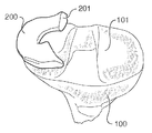
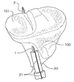
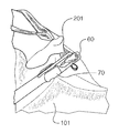
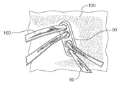
뼈와 연조직의 일 부분이 도 1에 도시되어 있다. 특히, 경골 고평부(101)를 갖는 경골(100)이 내측 반월판(200)의 일 부분과 함께 도시되어 있다. 도 1에서, 부분적으로 절제된 내측 반월판(200)의 후근(201)이 경골 고평부(101)로부터 분리되어 있고, 결과적으로 재부착에 의한 수복이 필요하다. 본원에서 설명되는 방법 및 장치는 내측 반월판의 후근 및 외측에서 파열된 내측 반월판의 재부착과 관련하여 도시되어 있지만; 설명되는 방법 및 장치는 뼈에 대한 연조직의 부착 또는 재부착을 포함한 다른 수복에 동일하게 적용 가능할 수 있다. 재부착 또는 수복은 예를 들어 그리고 제한적이지 않게, 외측 반월판 또는 임의의 다른 연조직 구조물 상에서 달성될 수 있다. 부착 또는 재부착되는 연조직은 연골, 인대, 건, 또는 이러한 연조직 또는 다른 연조직의 임의의 조합 또는 일부일 수 있다. 연조직이 재부착되는 뼈는, 예를 들어 그리고 제한적이지 않게, 경골, 대퇴골, 슬개골, 상완골, 요골, 또는 이러한 뼈 또는 다른 뼈의 임의의 조합 또는 일부일 수 있다. 다양한 실시예에서 부착되거나, 재부착되거나, 수복되거나, 뼈와 접촉되는 연조직은 결과적으로 뼈 속으로 성장할 기회가 주어질 수 있다. 본 발명의 방법 실시예, 및 다양한 방법 실시예를 실행하기 위해 채용될 수 있는 기구 및 임플란트를 설명하기 위해 도 2 - 도 21 및 도 23 - 도 25가 참조될 것이다.A portion of the bone and soft tissue is shown in FIG. Particularly, the
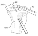
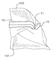
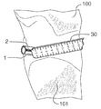
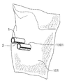
방법 실시예는 제1 터널의 출구가 재부착되는 연조직의 제1 부분 부근에 있도록, 경골과 같은 뼈를 통해 제1 터널을 생성하는 단계를 포함한다. 도 2에 도시된 바와 같이, 조준기(10)가 재부착되는 내측 반월판(200)의 후근(201)의 제1 부분 부근에서 경골 고평부(101)를 통한 출구를 향하도록 사용된다. 본원에서 개시되는 방법의 조준기(10) 및 다른 기구 및 임플란트는 내시경 시각화 및 조작 도구와 조합하여 사용될 수 있다. 도 3에 도시된 바와 같이, 드릴 비트(15)가 조준기 포인트(11)에 대해 약간 원위에서 경골 고평부(101)를 빠져나오는 것으로 도시되어 있다. 드릴 비트(15)와 같은 드릴 비트는 터널을 생성하기 위해 독립적으로 또는 다른 기구와 관련하여 사용될 수 있다. 예를 들어, 드릴 비트는 도 4에 도시된 슬리브형 드릴(1)과 같은 슬리브형 드릴과 조합하여 사용될 수 있다. 추가의 예로써, 슬리브형 드릴(1) 및 드릴 비트(15)는 사용 중에 슬리브형 드릴(1)의 내부에 드릴 비트(15)를 삽입함으로써 동시에, 또는 먼저 드릴 비트(15)로 구멍을 뚫고 이어서 드릴 비트(15)에 의해 생성된 구멍을 통해 슬리브형 드릴(1)을 통과시킴으로써 순차적으로, 사용될 수 있다. 비트 이외의 드릴 메커니즘의 비제한적인 예는 오거(auger), 스타일릿, 코르크 스크루, 또는 임의의 다른 효과적인 드릴링 메커니즘을 포함한다. 뼈를 통해 터널을 효과적으로 생성하기 위해 사용될 수 있는 임의의 다른 기구 또는 기구들의 조합이 다양한 실시예에서 사용될 수 있다. 슬리브형 드릴(1)은 치형부, 및 하나의 방사상 위치에서 슬리브형 드릴(1)을 따라 종방향으로 라인을 제공함으로써 슬리브형 드릴(1)의 방사상 위치를 지정하는 원위 단부 부근의 원위 표지(2)를 포함하는 튜브형 샤프트이다. 슬리브형 드릴(1)은 원위 표지(2)의 방사상 위치와 상관되는 그의 근위 단부 부근의 근위 표지(3)를 또한 포함한다(도 5). 이러한 예에서, 근위 표지(3)는 또한 하나의 방사상 위치에서 슬리브형 드릴(1)을 따라 종방향으로 표지된 라인이다. 도시된 실시예에서, 원위 표지(2) 및 근위 표지(3)는 슬리브형 드릴(1)을 따라 종방향으로 표지된 동일한 라인의 일부이지만; 다른 실시예에서, 원위 표지 및 근위 표지는 동일한 라인을 따른 공존성을 반드시 포함하지는 않는 몇몇 상관 관계를 가질 수 있다.The method embodiment includes creating a first tunnel through a bone, such as the tibia, such that the outlet of the first tunnel is adjacent a first portion of the soft tissue to which it is reattached. The
도 4에 도시된 바와 같이, 방법 실시예는 슬리브형 드릴(1) 상의 원위 표지(2)의 방사상 위치를 관찰하고, 제2 터널의 출구가 재부착되는 연조직의 제2 부분 부근에 있도록 원위 표지(2)가 경골(100)을 통해 생성되는 제2 터널에 대한 원하는 방사상 위치를 표시하도록 슬리브형 드릴(1)을 배향하는 단계를 포함할 수 있다. 특히 이러한 실시예에서, 후근(201)에 부착된 봉합사의 조화된 인장에 의해 내측 반월판(202)의 원하는 위치를 이동시키기 위해 후근(201)의 제1 부분에 대해 이루어진 부착과 조합하여 사용될 수 있는 봉합사가 부착될 수 있는 후근(201)의 제2 부분을 선택하는 것이 바람직할 수 있다. 도 4에 도시된 바와 같이, 슬리브형 드릴(1)의 원위 표지(2)는 경골(100) 내에 생성되는 제2 터널을 향한 방사상 방향으로 배향된다. 이러한 예는 제1 터널의 출구로부터 제2 터널의 원하는 위치까지의 거리를 측정하는 것을 추가로 도시한다. 구체적으로, 도 4에 도시된 바와 같은 측정 기구(30)는 내시경을 통해 관찰되며, 경골(100)을 통한 제2 터널에 대해 적절하다고 믿어지는 거리를 선택하기 위해 원위 표지(2)의 방향으로 배향될 수 있다.As shown in Figure 4, the method embodiment includes the steps of observing the radial position of the
몇몇 방법 실시예는 배향된 원위 표지와 상관되는 근위 표지의 방사상 위치를 관찰하는 단계를 또한 포함한다. 도시된 실시예에서, 이는 원위 표지(2)의 배향된 위치와 상관되는 근위 표지(3)의 방사상 위치를 관찰하는 단계를 포함할 수 있다. 그러한 관찰은 제1 터널에 대해 제2 터널을 생성하기 위한 배향을 사용자에게 제공할 수 있다.Some method embodiments also include observing the radial position of the proximal marker correlated with the oriented distal marker. In the illustrated embodiment, this may include observing the radial position of the
부착구(20)가 도 6에 도시되어 있고, 부착구(20)의 방사상 위치를 지정하기 위한 부착구 표지(21)를 포함한다. 부착구(20)는 근위 표지(3)의 방사상 위치를 시스템의 사용자에게 추가로 돌출시키기 위해 부착구 표지(21)가 근위 표지(3)와 정렬되도록 슬리브형 드릴(1)의 근위 단부와 결합하도록 구성된다. 도 7에 도시된 부착구(20)는 배향된 원위 표지(2) 및 근위 표지(3)와 연관되는 방사상 위치에서 부착구 표지(21)를 돌출시킨다. 부착구(20)는 슬리브형 드릴(1)을 조작하는 데 유용한 손잡이, 척, 또는 다른 메커니즘일 수 있다. 다양한 실시예의 부착구는 손에 의해 조작되거나 회전되도록 구성될 수 있거나, 추가의 동력식 또는 비동력식 조작 장치로의 커플링을 제공할 수 있다. 부착구(20) 또는 유사한 부착구는 슬리브형 드릴(1)을 원하는 방사상 위치로 회전시키기 위해 사용될 수 있거나, 터널의 드릴링 또는 다른 생성을 이루기 위해 조작되거나 회전될 수 있다. 근위 표지(3)의 방사상 위치를 직접 관찰한 후에, 또는 부착구 표지(21)에 의해 돌출될 때, 제2 터널은 근위 표지(3)에 의해 표시된 제1 터널로부터의 방사상 방향에서 제1 터널에 대해 생성될 수 있다. 도시된 실시예에서, 제1 터널에 대한 제2 터널의 위치는 직접 상관 관계이다. 그러나, 다른 실시예에서, 다양한 기구 실시예에 의해 측정될 때 제1 터널과 제2 터널 사이에서 방사상 오프셋 및 선형 오프셋 중 하나 또는 모두가 있을 수 있다.
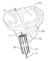
몇몇 방법 실시예는 제1 터널에 대해 위치되어 제2 터널의 생성을 안내하도록 사용될 수 있는 도 8 및 도 9에 도시된 드릴 가이드(40)와 같은 드릴 가이드의 사용을 포함한다. 드릴 가이드(40)는 도시된 실시예에서 중심 구멍(43)으로부터 연장하는 복수의 방사상 표식(41)을 갖는다. 드릴 가이드(40)는 원통형 드릴 가이드이고, 중심 구멍(43)은 원통의 단면 중심에 있으며, 드릴 가이드가 제2 터널을 생성하기 위해 사용되도록 위치될 때 제1 터널과 동심으로 정렬되도록 구성된다. 다른 실시예에서, 드릴 가이드가 그 둘레에서 제1 터널 내에 위치된 기구와 맞물릴 수 있는 중심 구멍 또는 지점은 드릴 가이드의 기하학적 중심 내에 있을 수 있거나, 몇몇 미리 결정된 방사상 관계로 기하학적 중심으로부터 오프셋될 수 있다. 그러한 드릴 가이드는 상대 방사상 위치를 지정하는 표식을 포함할 수 있다. 또 다른 실시예에서, 제1 터널에 대한 제2 터널의 드릴링은 드릴 가이드의 세트에 의해 또는 제2 터널이 제1 터널에 대해 생성되도록 허용하는 임의의 다른 방법 또는 기구의 사용에 의해 달성될 수 있다. 도시된 드릴 가이드(40)는 슬리브형 드릴(1)의 적어도 일 부분 위에 끼워지도록 구성된다. 슬리브형 드릴(1) 또는 다른 제1 기구에 대해 드릴 가이드를 위치시키기 위한 임의의 다른 효과적인 메커니즘이 다른 실시예에서 채용될 수 있다. 방사상 표식(41)은 도 9에 도시된 바와 같이, 제2 터널의 생성을 위한 방사상 방향을 제공하기 위해 근위 표지(3)와 정렬되도록 구성된다. 몇몇 실시예의 제2 터널은 제2 터널의 생성이 그를 통해 달성되는 안내 구멍(45)과 실질적으로 평행한 중심 구멍(43)의 사용에 의해 제1 터널과 실질적으로 평행하게 생성된다. 각각의 방사상 표식(41)은 그의 길이를 따라, 중심 구멍(43)으로부터의 미리 결정된 거리에서 안내 구멍(45)을 포함한다. 도시된 실시예에서, 표지(47)는 중심 구멍(43)과 각각의 방사상 표식(41)을 따른 각각의 안내 구멍(45) 사이의 미리 결정된 거리를 라벨링한다. 도 9에 도시된 바와 같이, 근위 표지(3)는 슬리브형 드릴(1)이 위치된 제1 터널로부터의 7mm의 미리 결정된 선형 거리를 갖는, 안내 구멍(45)을 통해 생성되는 제2 터널의 위치를 방사상으로 정렬시키기 위해 드릴 가이드(40) 상의 표식(41)과 정렬된다. 7mm의 선택된 선형 거리는 관찰에 의해 그리고 도 4에 도시된 측정 기구(30)의 사용에 의해 선택될 수 있다. 몇몇 실시예에서, 최종 선형 거리는 측정 기구(30)와 같은 측정 기구에 의한 또는 슬리브형 드릴의 크기, 터널 직경, 또는 몇몇 다른 공지된 인자를 고려하는 오프셋에 의해 변경된 몇몇 다른 기구에 의한 측정에 기초할 수 있다.Some method embodiments include the use of a drill guide, such as the
제2 터널은, 예를 들어, 본원에서 설명되는 드릴 비트(15)일 수 있는 드릴 비트와 같은 제2 기구에 의해 생성될 수 있다. 드릴 비트는 터널을 생성하기 위해 독립적으로 또는 다른 기구와 관련하여 사용될 수 있다. 예를 들어, 드릴 비트는 도 10 및 도 11에 도시된 슬리브형 드릴(1001)과 같은 슬리브형 드릴과 조합하여 사용될 수 있다. 슬리브형 드릴(1001) 및 드릴 비트(15)는 사용 중에 슬리브형 드릴(1001)의 내부에 드릴 비트(15)를 삽입함으로써 동시에, 또는 먼저 드릴 비트(15)로 구멍을 뚫고 이어서 드릴 비트(15)에 의해 생성된 구멍을 통해 슬리브형 드릴(1001)을 통과시킴으로써 순차적으로, 사용될 수 있다. 슬리브형 드릴(1001) 및 드릴 비트(15) 중 하나 또는 모두는 제2 터널을 생성하기 위해 안내 구멍(45)과 같은 안내 구멍을 통해 사용될 수 있다. 비트 이외의 드릴 메커니즘의 비제한적인 예는 오거, 스타일릿, 코르크 스크루, 또는 임의의 다른 효과적인 드릴링 메커니즘을 포함한다. 뼈를 통해 터널을 효과적으로 생성하기 위해 사용될 수 있는 임의의 다른 기구 또는 기구들의 조합이 다양한 실시예에서 사용될 수 있다.The second tunnel may be created by a second mechanism, such as a drill bit, which may be, for example, the
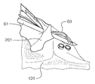
예시적인 내시경 관문(50)이 도 11에 도시되어 있고, 이를 통해 본원에서 개시되는 방법의 단계들이 달성되거나 관찰될 수 있다. 복수의 내시경 관문이 본원에서 개시되는 방법의 단계들을 달성하거나 관찰하기 위해 사용될 수 있다. 도 10에 도시된 바와 같이, 본원에서 개시되는 바와 같이 정렬된 제2 터널을 통해 위치된 슬리브형 드릴(1001)은 원위 표지(2)의 배향과 일치하는 방사상 방향으로 위치된다.An exemplary
도 12에 도시된 바와 같이, 슬리브형 드릴(1, 1001)은 경골 고평부(101)와 동일 평면으로 놓이도록 취출된다. 사용자는 또한 슬리브형 드릴(1, 1001)들 중 하나 또는 모두를 경골 고평부(101)보다 약간 하위가 되도록 취출하는 것을 선택할 수 있다. 봉합사 통과기(61) 상으로 장입된 봉합사(60)가 도 12에서 후근(201)의 제1 부분에 결합된 것으로 도시되어 있다. 루프형 파지기(70)가 도 14에 도시된 바와 같이, 후근(201)을 통해 단순 스티치를 남겨 두도록 후근(201)을 통해 봉합사(60)의 레그를 당기기 위해 도 13에서 봉합사(60)의 일 부분을 파지하는 것으로 도시되어 있다. 루프형 안내 와이어(80)가 그 다음 도 15에 도시된 바와 같이 제1 터널 또는 제2 터널 중 하나를 통해 도입될 수 있다. 도시된 실시예에서, 루프형 안내 와이어(80)는 제1 터널을 통해 도입된다. 도 15 및 도 16에 도시된 바와 같이, 루프형 안내 와이어(80) 및 봉합사(60)는 내시경 캐뉼라(150)를 통해 회수될 수 있다. 방법 실시예는 제1 터널로부터 슬리브형 드릴(1)을 취출하고, 도 17에 도시된 봉합사를 생성하기 위해 봉합사(60)를 루프형 안내 와이어(80)와 함께 제1 터널을 통해 당기는 단계를 추가로 포함할 수 있다. 다른 실시예에서, 제1 봉합사(60)는 제2 터널 또는 경골을 통한 다른 터널을 통해 통과될 수 있다. 몇몇 실시예는 하나의 터널을 통해 봉합사의 하나의 레그를 그리고 다른 터널을 통해 봉합사의 다른 레그를 통과시키는 단계를 또한 포함할 수 있다. 연조직에 봉합사를 결합시키고 제1 터널을 통해 봉합사를 통과시키는 임의의 다른 효과적인 방법이 본 발명의 다른 실시예에서 채용될 수 있다. 유사한 방식으로, 제2 봉합사(160)가 후근(201)의 제2 부분에 결합되어, 제1 터널 및 제2 터널 중 적어도 하나를 통해 통과될 수 있다. 제2 봉합사(160)는 도 18에서 후근(201)에 결합되어 제2 터널로부터 연장하는 것으로 도시되어 있다. 도시된 봉합사(60, 160)는 유리한 구조로 직조된 복수의 스트랜드를 포함하는 울트라테이프(ULTRATAPE) 상표의 테이프형 봉합사이다. 울트라테이프는 미국 테네시주 멤피스 브룩스 로드 1450 소재의 스미쓰 앤드 넵퓨, 인크.(Smith & Nephew, Inc.)의 상표이다. 그러나, 다른 실시예는 연조직과 뼈 사이를 부착할 수 있는 임의의 효과적인 공지된 또는 이후에 개발될 봉합사 또는 유사한 구조물일 수 있다.As shown in Fig. 12, the
몇몇 실시예들의 추가의 단계는 후근(201)의 제1 부분을 경골 고평부(101)와 접촉시키기 위해 제1 봉합사(60)를 인장시키는 단계를 포함한다. 제1 봉합사(60)를 인장시키는 단계는 연조직을 인장에 의해 원하는 위치로 이동시키는 단계를 포함할 수 있다. 바꾸어 말하면, 제1 봉합사(60) 내의 장력을 증가시키는 것은 후근(201)의 제1 부분을 제1 터널을 향해 당길 수 있고, 제1 봉합사(60) 내의 장력을 감소시키는 것은 제2 봉합사(160)와 같은 다른 봉합사로부터의 장력이 후근(201)을 제1 터널로부터 멀리 이동시키도록 허용할 수 있다. 제1 봉합사(60)에 대한 원하는 장력이 달성되면, 제1 봉합사(60)는 경골(100)에 대해 고정될 수 있다. 도 18 - 도 21에 도시된 바와 같이, 제1 봉합사(60)는 제1 뼈 터널의 진입 지점 부근의 앵커(90)를 통해 경골(100) 내로 통과된다. 제1 봉합사(60)는 도 20에 도시된 바와 같이, 앵커(90)에 인접하여 매듭을 묶음으로써 원하는 장력으로 앵커(90)에 고정된다. 앵커(90)는 엔도버튼(ENDOBUTTON) 상표의 정착 장치이다. 엔도버튼은 미국 테네시주 멤피스 브룩스 로드 1450 소재의 스미쓰 앤드 넵퓨, 인크.의 등록 상표이다. 그러나, 다른 실시예는 와셔, 다른 유형의 전용 봉합사 앵커, 끼워 맞춤 스크루, 기둥, 건고정 스크루, 또는 무매듭 앵커와 같지만 이들로 제한되지 않는 임의의 효과적인 앵커 또는 유사한 장치의 사용을 포함할 수 있다.A further step of some embodiments includes tensioning the
몇몇 실시예의 추가의 단계는 후근(201)의 제2 부분을 경골 고평부(101)와 접촉시키기 위해 제2 봉합사(160)를 인장시키는 단계를 포함한다. 제2 봉합사를 인장시키는 단계는 연조직을 인장에 의해 원하는 위치로 이동시키는 단계를 포함할 수 있다. 바꾸어 말하면, 제2 봉합사(160) 내의 장력을 증가시키는 것은 후근(201)의 제2 부분을 제2 터널을 향해 당길 수 있고, 제2 봉합사(160) 내의 장력을 감소시키는 것은 제1 봉합사(60)와 같은 다른 봉합사로부터의 장력이 후근(201)을 제2 터널로부터 멀리 이동시키도록 허용할 수 있다. 제2 봉합사(160)에 대한 원하는 장력이 달성되면, 제2 봉합사(160)는 경골(100)에 대해 고정될 수 있다. 도 18 - 도 21에 도시된 바와 같이, 제2 봉합사(160)는 제2 뼈 터널의 진입 지점 부근의 앵커(90)를 통해 경골(100) 내로 통과된다. 제2 봉합사(160)는 도 20에 도시된 바와 같이, 앵커(90)에 인접하여 매듭을 묶음으로써 원하는 장력으로 앵커(90)에 고정된다. 도시된 실시예에서, 제2 봉합사(160)는 제1 봉합사(60)와 동일한 앵커(90)에 고정된다. 다른 실시예에서, 다양한 봉합사가 분리된 앵커들에 고정될 수 있거나, 더 일반적으로 독립적으로 또는 상호 의존적으로 고정될 수 있다.A further step of some embodiments includes tensioning the
제1 봉합사(60) 및 제2 봉합사(160)의 독립적인 고정은 적어도 봉합사들 중 하나 또는 그의 각각의 연결이 파손된 상황에서 가치가 있다. 개시되는 실시예에 의하면, 제1 봉합사(60) 또는 제2 봉합사(160) 중 하나의 파손은 다른 봉합사에 영향을 주지 않는다. 결과적으로, 후근(201)은 제1 봉합사(60) 또는 제2 봉합사(160) 중 하나의 파손이 발생하면, 경골 고평부(101)에 대해 제 위치에 적어도 부분적으로 유지될 수 있다. 몇몇 상황에서, 이러한 구성은 후근(201)을 재부착하기 위한 추가의 수술을 회피하는 데 있어서 중요할 수 있다. 유사하게, 제1 봉합사(60) 및 제2 봉합사(160)의 연결의 독립성은 본원의 봉합사의 인장에 관한 단계와 관련하여 설명되는 바와 같이, 후근(201)을 더 효과적으로 위치시키는 데 있어서 가치가 있을 수 있다.The independent fixation of the
뼈에 대한 연조직의 완성된 재부착이 도 21에 도시되어 있다. 특히, 내측 반월판(200)의 후근(201)은 제1 봉합사(60) 및 제2 봉합사(160)로 경골 고평부(101)에 재부착된 것으로 도시되어 있다.The complete reattachment of the soft tissue to the bone is shown in FIG. Particularly, the trailing
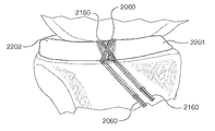
제1 터널의 출구가 재부착되는 연조직의 제1 부분 부근에 있도록 경골과 같은 뼈를 통해 제1 터널을 생성하는 단계를 포함하는 다른 방법 실시예가 도 22 - 도 25에 도시되어 있다. 조준기(10)(도 2)와 유사한 조준기가 재부착되는 내측 반월판(2200)의 연조직의 제1 부분(2201)(도 22 - 도 25) 부근의 경골 고평부(101)를 통한 출구를 향하도록 사용될 수 있다. 본원에서 개시되는 방법의 조준기 및 다른 기구 및 임플란트는 내시경 시각화 및 조작 도구와 조합하여 사용될 수 있다. 드릴 비트가 터널을 생성하기 위해 독립적으로 또는 다른 기구와 관련하여 사용될 수 있다. 예를 들어, 드릴 비트는 도 23에 도시된 슬리브형 드릴(2001)과 같은 슬리브형 드릴과 조합하여 사용될 수 있다. 추가의 예로써, 슬리브형 드릴(2001) 및 드릴 비트는 사용 중에 슬리브형 드릴(2001)의 내부에 드릴 비트를 삽입함으로써 동시에, 또는 먼저 드릴 비트로 구멍을 뚫고 이어서 드릴 비트에 의해 생성된 구멍을 통해 슬리브형 드릴(2001)을 통과시킴으로써 순차적으로, 사용될 수 있다. 비트 이외의 드릴 메커니즘의 비제한적인 예는 오거, 스타일릿, 코르크 스크루, 또는 임의의 다른 효과적인 드릴링 메커니즘을 포함한다. 뼈를 통해 터널을 효과적으로 생성하기 위해 사용될 수 있는 임의의 다른 기구 또는 기구들의 조합이 다양한 실시예에서 사용될 수 있다. 슬리브형 드릴(2001)은 치형부, 및 방사상 위치에서 슬리브형 드릴(2001)을 따라 종방향으로 라인을 제공함으로써 슬리브형 드릴(2001)의 방사상 위치를 지정하는 원위 단부 부근의 원위 표지(2002)를 포함하는 튜브형 샤프트이다. 슬리브형 드릴(2001)은 원위 표지(2002)의 방사상 위치와 상관되는 그의 근위 단부 부근의 근위 표지(2003)를 또한 포함한다. 이러한 예에서, 근위 표지(2003)는 또한 방사상 위치에서 슬리브형 드릴(1)을 따라 종방향으로 표지된 라인이다. 도시된 실시예에서, 원위 표지(2002) 및 근위 표지(2003)는 슬리브형 드릴(2001)을 따라 종방향으로 표지된 동일한 라인의 일부이지만; 다른 실시예에서, 원위 표지 및 근위 표지는 동일한 라인을 따른 공존성을 반드시 포함하지는 않는 몇몇 상관 관계를 가질 수 있다.Another method embodiment is illustrated in FIGS. 22-25 which includes creating a first tunnel through a bone, such as the tibia, so that the outlet of the first tunnel is adjacent to a first portion of the soft tissue to be reattached. The sphincter similar to sphincter 10 (Fig. 2) is directed to the exit through
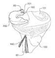
도 23에 도시된 바와 같이, 방법 실시예는 슬리브형 드릴(2001) 상의 원위 표지(2002)의 방사상 위치를 관찰하고, 제2 터널의 출구가 재부착되는 연조직의 제2 부분 부근에 있도록 원위 표지(2002)가 경골(100)을 통해 생성되는 제2 터널에 대한 원하는 방사상 위치를 표시하도록 슬리브형 드릴(2001)을 배향하는 단계를 포함할 수 있다. 특히, 이러한 실시예에서, 연조직의 제1 부분(2201) 및 제2 부분(2202)에 부착된 봉합사의 조화된 인장에 의해 내측 반월판(2200) 또는 그의 일부의 원하는 위치를 이동시키기 위해 사용될 수 있는 봉합사가 부착될 수 있는 내측 반월판(2200)의 연조직의 제1 부분(2201) 및 내측 반월판(2200)의 연조직의 제2 부분(2202)을 선택하는 것이 바람직할 수 있다. 도 24에 도시된 바와 같이, 제1 봉합사(2060)가 내측 반월판(2200)의 연조직의 제1 부분(2201)에 결합되며, 제1 터널의 뼈로부터의 출구(2300)로부터 제1 거리 및 제1 방향이다. 제2 봉합사(2160)가 제2 터널의 뼈로부터의 출구(2301)로부터 제2 거리 및 제2 방향이다. 도시된 실시예에서, 제1 방향 및 제2 방향은 제1 봉합사(2060) 및 제2 봉합사(2160) 중 하나 또는 모두가 인장될 때, 연조직의 제1 부분(2201) 및 연조직의 제2 부분(2202)이 서로를 향해 적어도 부분적으로 당겨지도록 실질적으로 반대 방향이다. 이러한 관계는 연조직의 제1 부분(2201) 및 제2 부분(2202)을 함께 당기는 (수렴하는 화살표(2250)들) 제1 봉합사(2060) 및 제2 봉합사(2160)에 인가되는 장력을 도시하는 화살표(2350)에 의해 도 24에 추가로 도시되어 있다. 본원에서 사용되는 바와 같이, 반대 방향이라는 용어는 단지 정확하게 반대인 것을 의미하지는 않고, 인장될 때 부착된 조직까지 가로지르는 각각의 터널로부터 연장하는 봉합사가, 부착된 조직에 대한 힘 또는 이동의 적어도 몇몇 반대 벡터를 생성하도록, 대체로 반대되는 방향들을 또한 포함할 수 있다.23, the method embodiment observes the radial position of the
도 23에 도시된 바와 같이, 슬리브형 드릴(2001) 상의 원위 표지(2002)는 경골(100) 내에 생성되는 제2 터널을 향한 방사상 방향으로 배향된다. 거리는 제1 터널의 출구(2300)로부터 제2 터널의 원하는 위치까지 측정될 수 있다. 이러한 실시예에서, 측정은 제1 터널의 종축으로부터 직교하여 달성된다. 도 4에 도시된 바와 같은 측정 기구(30)가 내시경을 통해 관찰될 수 있으며, 경골(100)을 통한 제2 터널에 대해 적절한 것으로 믿어지는 거리를 선택하기 위해 원위 표지(2002)의 방향으로 배향된다.23, the
몇몇 방법 실시예는 배향된 원위 표지와 상관되는 근위 표지의 방사상 위치를 관찰하는 단계를 또한 포함한다. 도시된 실시예에서, 이는 원위 표지(2002)의 배향된 위치와 상관되는 근위 표지(2003)의 방사상 위치를 관찰하는 단계를 포함할 수 있다. 그러한 관찰은 제1 터널에 대해 제2 터널을 생성하기 위한 배향을 사용자에게 제공할 수 있다.Some method embodiments also include observing the radial position of the proximal marker correlated with the oriented distal marker. In the illustrated embodiment, this may include observing the radial position of the
도 6에 도시된 부착구(20)와 같은 부착구는 도 6과 관련하여 설명된 바와 같이 실질적으로 슬리브형 드릴(2001)과 함께 사용될 수 있다. 도시된 실시예에서, 제1 터널에 대한 제2 터널의 위치는 직접 상관 관계이다. 그러나, 다른 실시예에서, 다양한 기구 실시예에 의해 측정될 때 제1 터널과 제2 터널 사이에서 방사상 오프셋 및 선형 오프셋 중 하나 또는 모두가 있을 수 있다.An attachment such as
몇몇 방법 실시예는 제1 터널에 대해 위치되어 제2 터널의 생성을 안내하도록 사용될 수 있는 도 8, 도 9, 및 도 23에 도시된 드릴 가이드(40)와 같은 드릴 가이드의 사용을 포함한다. 도 23에 도시된 실시예와 함께 드릴 가이드(40)의 사용은 도 8 및 도 9와 관련하여 설명된 사용과 실질적으로 동일하다.Some method embodiments include the use of a drill guide, such as the
제2 터널은, 예를 들어, 본원에서 설명되는 드릴 비트(15)일 수 있는 드릴 비트와 같은 제2 기구에 의해 생성될 수 있다. 드릴 비트는 터널을 생성하기 위해 독립적으로 또는 다른 기구와 관련하여 사용될 수 있다. 예를 들어, 드릴 비트는 도 23에 도시된 슬리브형 드릴(3001)과 같은 슬리브형 드릴과 조합하여 사용될 수 있다. 슬리브형 드릴(3001) 및 드릴 비트는 사용 중에 슬리브형 드릴(3001)의 내부에 드릴 비트를 삽입함으로써 동시에, 또는 먼저 드릴 비트로 구멍을 뚫고 이어서 드릴 비트에 의해 생성된 구멍을 통해 슬리브형 드릴(3001)을 통과시킴으로써 순차적으로, 사용될 수 있다. 슬리브형 드릴(3001) 및 드릴 비트 중 하나 또는 모두는 제2 터널을 생성하기 위해 안내 구멍(45)과 같은 안내 구멍을 통해 사용될 수 있다. 비트 이외의 드릴 메커니즘의 비제한적인 예는 오거, 스타일릿, 코르크 스크루, 또는 임의의 다른 효과적인 드릴링 메커니즘을 포함한다. 뼈를 통해 터널을 효과적으로 생성하기 위해 사용될 수 있는 임의의 다른 기구 또는 기구들의 조합이 다양한 실시예에서 사용될 수 있다.The second tunnel may be created by a second mechanism, such as a drill bit, which may be, for example, the
제1 봉합사(2060) 및 제2 봉합사(2160)가 도 12 - 도 20과 관련하여 본원에서 설명된 방법 및 방법의 변경예를 포함하여, 임의의 효과적인 방법에 의해 도 24 및 도 25에 도시된 바와 같이 터널을 통해 통과될 수 있다. 도시된 봉합사(2060, 2160)는 보편적인 봉합사이지만, 다른 봉합사 실시예는 연조직과 뼈 사이를 부착할 수 있는 임의의 효과적인 공지된 또는 이후에 개발될 봉합사 또는 유사한 구조물을 포함할 수 있다. 예시적인 봉합사는 유리한 구조로 직조된 복수의 스트랜드를 갖는 울트라테이프 상표의 테이프형 봉합사를 포함하지만 이로 제한되지 않는다. 도 25에 도시된 완성된 재부착은 수복되는 내측 반월판의 2개의 부분들 각각 내에서 2개의 봉합사를 포함한다. 다른 실시예는 임의의 효과적인 개수의 봉합사를 포함할 수 있거나, 상이한 개수의 봉합사를 포함할 수 있거나, 연조직의 제1 부분(2201) 및 제2 부분(2202) 각각 내에서 봉합사의 완전한 생략을 보일 수 있다. 몇몇 실시예에서, 연조직의 부분들은 뼈를 통한 하나 이상의 터널을 통해 연결될 수 있거나 그렇지 않을 수 있는 봉합사로 함께 직접 봉합될 수 있다. 연조직의 부분들의 그러한 연결은 또한 스테이플, 클립, 또는 임의의 효과적인 메커니즘 또는 기술의 사용에 의해 달성될 수 있다.The
위에서 도 24와 관련하여 설명된 인장의 단계에 추가하여, 몇몇 실시예는 연조직의 제1 부분(2201)을 경골 고평부(101)와 접촉시키기 위해 제1 봉합사(2060)를 인장시키는 단계를 포함한다. 제1 봉합사(2060)를 인장시키는 단계는 연조직을 인장에 의해 원하는 위치로 이동시키는 단계를 포함할 수 있다. 바꾸어 말하면, 제1 봉합사(2060) 내의 장력을 증가시키는 것은 연조직의 제1 부분(2201)을 제1 터널을 향해 당길 수 있고, 제1 봉합사(2060) 내의 장력을 감소시키는 것은 다른 봉합사로부터의 장력이 연조직의 제1 부분(2201)을 제1 터널로부터 멀리 이동시키도록 허용할 수 있다. 제1 봉합사(2060)에 대한 원하는 장력이 달성되면, 제1 봉합사(2060)는 경골(100)에 대해 고정될 수 있다. 와셔, 다른 유형의 전용 봉합사 앵커, 끼워 맞춤 스크루, 기둥, 건고정 스크루, 또는 무매듭 앵커와 같지만 이들로 제한되지 않는 임의의 효과적인 앵커 또는 유사한 장치가 경골(100)에 대해 제1 봉합사(2060)를 고정하기 위해 사용될 수 있다. 몇몇 실시예는 연조직의 제2 부분(2202)을 경골 고평부(101)와 접촉시키기 위해 제2 봉합사(2160)를 인장시키는 단계를 포함한다. 제2 봉합사(2160)를 인장시키는 단계는 연조직을 인장에 의해 원하는 위치로 이동시키는 단계를 포함할 수 있다. 바꾸어 말하면, 제2 봉합사(2160) 내의 장력을 증가시키는 것은 연조직의 제2 부분(2202)을 제2 터널을 향해 당길 수 있고, 제2 봉합사(2160) 내의 장력을 감소시키는 것은 다른 봉합사로부터의 장력이 연조직의 제2 부분(2202)을 제2 터널로부터 멀리 이동시키도록 허용할 수 있다. 제2 봉합사(2160)에 대한 원하는 장력이 달성되면, 제2 봉합사(2160)는 경골(100)에 대해 고정될 수 있다. 와셔, 다른 유형의 전용 봉합사 앵커, 끼워 맞춤 스크루, 기둥, 건고정 스크루, 또는 무매듭 앵커와 같지만 이들로 제한되지 않는 임의의 효과적인 앵커 또는 유사한 장치가 경골(100)에 대해 제2 봉합사(2160)를 고정하기 위해 사용될 수 있다. 다양한 봉합사가 분리된 앵커들에 고정될 수 있거나, 더 일반적으로 독립적으로 또는 상호 의존적으로 고정될 수 있다.In addition to the steps of tension described above with respect to FIG. 24, some embodiments include tensioning
제1 봉합사(2060) 및 제2 봉합사(2160)의 독립적인 고정은 적어도 봉합사들 중 하나 또는 그의 각각의 연결이 파손되는 상황에서 가치가 있다. 개시되는 실시예에 의하면, 제1 봉합사(2060) 또는 제2 봉합사(2160) 중 하나의 파손은 다른 봉합사에 영향을 주지 않고, 연조직의 제1 부분(2201) 및 제2 부분(2202)이 함께 고정되면 전체 구성에 대해 제한된 영향을 갖는다. 내측 반월판(2200)은 제1 봉합사(2060) 또는 제2 봉합사(2160) 중 하나의 파손이 발생하면 경골 고평부(101)에 대해 제 위치에 적어도 부분적으로 유지될 수 있다. 몇몇 상황에서, 이러한 구성은 내측 반월판(2200)을 재부착하기 위한 추가의 수술을 회피하는 데 있어서 중요할 수 있다. 유사하게, 제1 봉합사(2060) 및 제2 봉합사(2160)의 연결의 독립성은 본원에서 봉합사의 인장에 관한 단계와 관련하여 설명된 바와 같이, 내측 반월판(2200)을 더 효과적으로 위치시키는 데 있어서 가치가 있을 수 있다.The independent fixation of the
뼈에 대한 연조직의 완성된 재부착이 도 25에 도시되어 있다. 특히, 내측 반월판(2200)은 제1 봉합사(2060), 제2 봉합사(2160), 및 추가의 봉합사로 경골 고평부(101)에 재부착된 것으로 도시되어 있다.The complete reattachment of the soft tissue to the bone is shown in Fig. Particularly, the
본 발명의 실시예는 2개의 터널 사이에서 제어된 거리 및 상대 방사상 위치로 뼈 속에 2개의 실질적으로 평행한 터널을 위치시키는 방법을 설명한다. 그러한 실시예는 2개의 상황: 도 2 - 도 7; 및 도 23에 도시되어 있다. 도 2 - 도 7에 도시된 하나의 예로서 그리고 본원에서 더 상세하게 설명되는 바와 같이, 제1 터널이 경골(100) 내에 생성될 수 있다. 그러한 방법 실시예는 제1 터널을 통해 슬리브형 드릴(1)과 같은 제1 기구를 위치시키는 단계를 추가로 포함할 수 있다. 슬리브형 드릴(1)은 슬리브형 드릴(1)의 방사상 위치를 지정하기 위한 그의 단부 부근의 원위 표지(2)를 포함한다. 슬리브형 드릴(1)은 원위 표지(2)와 상관되는 그의 근위 단부 부근의 근위 표지(3)를 또한 포함한다.An embodiment of the present invention describes a method of locating two substantially parallel tunnels in a bone at controlled distances and relative radial positions between two tunnels. Such an embodiment may include two situations: Figures 2-7; And FIG. 23, respectively. A first tunnel can be created in the
방법 실시예는 슬리브형 드릴(1) 상의 원위 표지(2)의 방사상 위치를 관찰하고, 원위 표지(2)가 경골(100)을 통해 생성되는 제2 터널에 대한 원하는 방사상 위치를 표시하도록 슬리브형 드릴(1)을 배향하는 단계를 포함할 수 있다. 도 4에 도시된 바와 같이, 슬리브형 드릴(1) 상의 원위 표지(2)는 경골(100) 내에 생성되는 제2 터널을 향한 방사상 방향으로 배향된다. 이러한 예는 제1 터널의 출구로부터 제2 터널의 원하는 위치까지의 거리를 측정하는 것을 추가로 도시한다. 구체적으로, 도 4에 도시된 바와 같은 측정 기구(30)가 내시경을 통해 관찰되며, 경골(100)을 통한 제2 터널에 대해 적절한 것으로 믿어지는 거리를 선택하기 위해 원위 표지(2)의 방향으로 배향될 수 있다.The method embodiment includes the steps of observing the radial position of the
몇몇 방법 실시예는 배향된 원위 표지와 상관되는 근위 표지의 방사상 위치를 관찰하는 단계를 또한 포함한다. 도시된 실시예에서, 이는 원위 표지(2)의 배향된 위치와 상관되는 근위 표지(3)의 방사상 위치를 관찰하는 단계를 포함할 수 있다. 그러한 관찰은 제1 터널에 대해 제2 터널을 생성하기 위한 배향을 사용자에게 제공할 수 있다.Some method embodiments also include observing the radial position of the proximal marker correlated with the oriented distal marker. In the illustrated embodiment, this may include observing the radial position of the
부착구(20)가 도 6에 도시되어 있고, 부착구(20)의 방사상 위치를 지정하기 위한 부착구 표지(21)를 포함한다. 부착구(20)는 근위 표지(3)의 방사상 위치를 시스템의 사용자에게 추가로 돌출시키기 위해 부착 표지(21)가 근위 표지(3)와 정렬되도록 슬리브형 드릴(1)의 근위 단부와 결합하도록 구성된다. 도 7에 도시된 바와 같은 부착구(20)는 배향된 원위 표지(2) 및 근위 표지(3)와 상관되는 방사상 위치에서 부착구 표지(21)를 돌출시킨다. 부착구(20)는 슬리브형 드릴(1)을 조작하는 데 유용한 손잡이, 척, 또는 다른 메커니즘일 수 있다. 다양한 실시예의 부착구는 손에 의해 조작되거나 회전되도록 구성될 수 있거나, 추가의 동력식 또는 비동력식 조작 장치로의 커플링을 제공할 수 있다. 부착구(20) 또는 유사한 부착구는 슬리브형 드릴(1)을 원하는 방사상 위치로 회전시키기 위해 사용될 수 있고, 터널의 드릴링 또는 다른 생성을 이루기 위해 조작되거나 회전될 수 있다. 근위 표지(3)의 방사상 위치를 직접 관찰한 후에, 또는 부착구 표지(21)에 의해 돌출될 때, 제2 터널이 근위 표지(3)에 의해 표시된 제1 터널로부터의 방사상 방향에서 제1 터널에 대해 생성될 수 있다. 도시된 실시예에서, 제1 터널에 대한 제2 터널의 위치는 직접 상관 관계이다. 그러나, 다른 실시예에서, 다양한 기구 실시예에 의해 측정될 때 제1 터널과 제2 터널 사이에서 방사상 오프셋 및 선형 오프셋 중 하나 또는 모두가 있을 수 있다.
2개의 터널 사이에서 제어된 거리 및 상대 방사상 위치로 뼈 속에 2개의 실질적으로 평행한 터널들을 위치시키는 것에 관련된 몇몇 방법 실시예는 제1 터널에 대해 위치되며 제2 터널의 생성을 안내하도록 사용될 수 있는, 도 8 및 도 9에 도시되고 본원에서 상세하게 설명되는 드릴 가이드(40)와 같은 드릴 가이드의 사용을 포함한다. 제2 터널은 제2 터널의 생성이 이를 통해 달성되는 안내 구멍(45)들 중 하나와 같은 안내 구멍과 실질적으로 평행한 중심 구멍(43)의 사용에 의해 제1 터널과 실질적으로 평행하게 생성될 수 있다. 제1 터널에 대해 가이드를 정착시키고 제1 터널에 대해 실질적으로 평행한 제2 터널로의 실질적으로 평행한 경로를 제공하기 위한 임의의 다른 효과적인 메커니즘이 다양한 실시예에서 사용될 수 있다.Some method embodiments relating to locating two substantially parallel tunnels in the bone at controlled distances and relative radial positions between two tunnels may be located relative to the first tunnel and may be used to guide the creation of a second tunnel , Use of a drill guide such as drill guide 40 shown in Figures 8 and 9 and described in detail herein. The second tunnel is created substantially parallel to the first tunnel by the use of a
2개의 터널 사이에서 제어된 거리 및 상대 방사상 위치로 뼈 속에 2개의 실질적으로 평행한 터널을 위치시키기 위해 사용되는 드릴 가이드(40)의 다른 특징 및 용도가 본원에서 상세하게 설명되는 드릴 가이드(40)의 특징 및 용도와 본질적으로 유사하다. 제2 터널은 터널을 생성하기 위해 독립적으로 또는 다른 기구와 관련하여 사용되는 드릴 비트와 같은 제2 기구에 의해 생성될 수 있다. 몇몇 실시예에서 사용될 수 있는 다른 드릴 터널 생성 메커니즘의 비제한적인 예는 오거, 스타일릿, 코르크 스크루, 또는 임의의 다른 효과적인 메커니즘을 포함한다.Other features and uses of the
아울러, 경골과 같은 뼈에 연조직을 재부착하는 방법이 제공된다. 예로서, 연조직은 내측 후근 부근의 반월판 조직 또는 파열된 외측 반월판 조직일 수 있다. 방법은 제1 터널의 출구가 재부착되는 연조직의 제1 부분 부근에 있도록 뼈를 통해 제1 터널을 생성하는 단계; 제1 터널을 통해 제1 기구를 위치시키는 단계 - 제1 기구는 제1 기구의 방사상 위치를 지정하기 위한 그의 원위 단부 부근의 원위 표지 및 원위 표지와 상관되는 그의 근위 단부 부근의 근위 표지를 포함함 -; 제1 기구 상의 원위 표지의 방사상 위치를 관찰하고, 제2 터널의 출구가 재부착되는 연조직의 제2 부분 부근에 있도록 원위 표지가 뼈를 통해 생성되는 제2 터널에 대한 원하는 방사상 위치를 표시하도록 제1 기구를 배향하는 단계; 배향된 원위 표지와 상관되는 근위 표지의 방사상 위치를 관찰하는 단계; 근위 표지에 의해 표시된 제1 터널로부터의 방사상 방향에서 제1 터널에 대해 제2 터널을 생성하는 단계; 재부착되는 연조직의 제1 부분에 제1 봉합사를 결합시키고, 제1 터널 및 제2 터널 중 적어도 하나를 통해 제1 봉합사를 통과시키는 단계; 재부착되는 연조직의 제2 부분에 제2 봉합사를 결합시키고, 제1 터널 및 제2 터널 중 적어도 하나를 통해 제2 봉합사를 통과시키는 단계; 연조직을 뼈와 접촉시키기 위해 제1 봉합사를 인장시키는 단계; 뼈에 대해 제1 봉합사를 고정하는 단계; 연조직을 뼈와 접촉시키기 위해 제2 봉합사를 인장시키는 단계; 및 뼈에 대해 제2 봉합사를 고정하는 단계를 포함한다.In addition, there is provided a method of reattaching soft tissue to a bone, such as a tibia. By way of example, the soft tissue may be meniscal tissue near the medial posterior muscle or ruptured lateral meniscus tissue. The method includes creating a first tunnel through the bone such that the exit of the first tunnel is adjacent a first portion of the soft tissue to which it is reattached; Positioning the first instrument through the first tunnel, the first instrument comprising a distal marker near its distal end for designating the radial position of the first instrument and a proximal marker near its proximal end correlated with the distal marker -; To observe the radial position of the distal marker on the first instrument and to indicate the desired radial position for the second tunnel through which the distal mark is produced through the bone so that the outlet of the second tunnel is near the second part of the soft tissue to be re- 1 orienting the device; Observing the radial position of the proximal marker correlated with the oriented distal marker; Creating a second tunnel with respect to the first tunnel in a radial direction from the first tunnel indicated by the proximal sign; Attaching a first suture to a first portion of the reattached soft tissue and passing the first suture through at least one of the first and second tunnels; Coupling a second suture to a second portion of the re-attached soft tissue and passing the second suture through at least one of the first and second tunnels; Tensioning the first suture to contact the soft tissue with the bone; Securing a first suture to the bone; Tensioning the second suture to bring the soft tissue into contact with the bone; And securing a second suture to the bone.
방법은 제1 터널을 통해 제1 기구를 위치시키는 단계를 포함할 수 있고, 뼈를 통해 제1 터널을 생성하는 단계를 포함한다.The method may include positioning a first mechanism through a first tunnel and creating a first tunnel through the bone.
방법은 원위 표지의 방사상 위치를 관찰하는 단계를 포함할 수 있고, 내시경을 통한 관찰을 포함한다.The method can include observing the radial position of the distal label and includes observation through an endoscope.
방법은 제1 터널의 출구로부터 제2 터널의 원하는 위치까지의 거리를 측정하는 단계를 포함할 수 있다.The method may include measuring the distance from the exit of the first tunnel to the desired location of the second tunnel.
방법은 제1 터널에 대해 위치되어 제2 터널의 생성을 안내하도록 사용되는 드릴 가이드를 포함할 수 있다. 아울러, 방법은 제1 터널에 대한 제2 터널의 위치를 방사상으로 정렬시키기 위해 드릴 가이드 상의 표식과 근위 표지를 정렬시키는 단계를 포함할 수 있다. 또한, 방법은 제1 터널과 동심으로 정렬되도록 구성되며 중심 구멍으로부터의 상이한 방사상 방향 및 상이한 거리에서 2개 이상의 안내 구멍을 포함하는 중심 구멍을 갖는 원통형 드릴 가이드와 근위 표지를 정렬시키는 단계를 포함할 수 있다. 아울러, 방법은 제1 기구의 적어도 일 부분 위에 중심 구멍을 끼우는 단계를 포함할 수 있다.The method may include a drill guide positioned relative to the first tunnel and used to guide the creation of the second tunnel. In addition, the method may include aligning the proximal marker with the mark on the drill guide to radially align the position of the second tunnel relative to the first tunnel. The method also includes aligning the proximal marker with a cylindrical drill guide configured to align concentrically with the first tunnel and having a central hole comprising two or more guide holes at different radial directions and different distances from the central hole . In addition, the method may include engaging a center hole on at least a portion of the first implement.
방법은 제2 터널을 통해 제2 기구를 위치시키는 단계를 포함할 수 있다. 아울러, 방법은 제2 터널을 통해 제2 기구를 위치시키는 단계를 포함할 수 있고, 뼈를 통해 제2 터널을 생성하는 단계를 포함한다.The method may include positioning the second mechanism through a second tunnel. In addition, the method may include positioning a second mechanism through a second tunnel, and creating a second tunnel through the bone.
방법은 제1 터널 및 제2 터널 중 적어도 하나를 통해 제1 봉합사 및 제2 봉합사를 통과시키는 단계를 포함할 수 있고, 제1 터널을 통해 제1 봉합사를 그리고 제2 터널을 통해 제2 봉합사를 통과시키는 단계를 포함한다.The method may include passing the first suture and the second suture through at least one of the first tunnel and the second tunnel and passing the first suture through the first tunnel and the second suture through the second tunnel .
방법은 제1 봉합사를 결합시키는 단계를 포함할 수 있고, 테이프형 봉합사인 봉합사를 결합시키는 단계를 포함한다. 추가로, 방법은 제2 봉합사를 결합시키는 단계를 포함할 수 있고, 테이프형 봉합사인 봉합사를 결합시키는 단계를 포함한다.The method can include bonding the first suture, and includes the step of bonding the suture, which is a tape-like suture. Additionally, the method may include bonding a second suture, and includes joining a suture that is a tape-shaped suture.
방법은 제1 봉합사를 인장시키는 단계를 포함할 수 있고, 연조직을 인장에 의해 원하는 위치로 이동시키는 단계를 포함한다.The method may include tensioning the first suture and moving the soft tissue to the desired location by stretching.
방법은 뼈에 대해 제1 봉합사를 고정하는 단계를 포함할 수 있고, 뼈 터널 진입 지점 부근에서 제1 봉합사를 고정하는 단계를 포함한다.The method can include securing a first suture to the bone and securing the first suture adjacent a bone tunnel entry point.
방법은 뼈에 대해 제1 봉합사를 고정하는 단계를 포함할 수 있고, 앵커에 제1 봉합사를 고정하는 단계를 포함한다.The method can include securing a first suture to the bone and securing the first suture to the anchor.
방법은 제2 봉합사를 인장시키는 단계를 포함할 수 있고, 연조직을 인장에 의해 원하는 위치로 이동시키는 단계를 포함한다.The method may include tensioning the second suture and moving the soft tissue to the desired location by stretching.
방법은 뼈에 대해 제2 봉합사를 고정하는 단계를 포함할 수 있고, 뼈 터널 진입 지점 부근에서 제2 봉합사를 고정하는 단계를 포함한다.The method may include securing a second suture to the bone and securing the second suture near the bone tunnel entry point.
방법은 뼈에 대해 제2 봉합사를 고정하는 단계를 포함할 수 있고, 앵커에 제2 봉합사를 고정하는 단계를 포함한다.The method may include securing a second suture to the bone and securing the second suture to the anchor.
방법은 뼈에 대해 제2 봉합사를 고정하는 단계를 포함할 수 있고, 제1 봉합사가 고정되어 있거나 고정될 앵커에 제2 봉합사를 고정하는 단계를 포함한다.The method can include securing the second suture to the bone and securing the second suture to the anchor to which the first suture is fixed or fixed.
방법은 재부착되는 연조직의 제1 부분을 재부착되는 연조직의 제2 부분에 결합시키는 단계를 포함할 수 있다.The method may include bonding a first portion of the re-attached soft tissue to a second portion of the re-attached soft tissue.
방법은 연조직의 제1 부분에 제1 봉합사를 결합시키는 단계를 포함할 수 있고, 제1 터널의 뼈로부터의 출구로부터 제1 거리 및 제1 방향인 연조직의 제1 부분에 제1 봉합사를 결합시키는 단계를 포함하고, 연조직의 제2 부분에 제2 봉합사를 결합시키는 단계는 제2 터널의 뼈로부터의 출구로부터 제2 거리 및 제2 방향인 연조직의 제2 부분에 제2 봉합사를 결합시키는 단계를 포함하고, 제1 방향 및 제2 방향은 실질적으로 반대되는 방향들이어서; 제1 봉합사 및 제2 봉합사 중 하나 또는 모두가 인장될 때, 연조직의 제1 부분 및 연조직의 제2 부분은 서로를 향해 적어도 부분적으로 당겨진다.The method may include attaching a first suture to a first portion of the soft tissue and coupling the first suture to a first portion of a soft tissue at a first distance and a first direction from an outlet from a bone of the first tunnel Wherein coupling the second suture to a second portion of the soft tissue comprises coupling a second suture to a second portion of the soft tissue at a second distance and a second direction from an exit from a bone of the second tunnel Wherein the first direction and the second direction are substantially opposite directions; When one or both of the first suture and the second suture are to be tensioned, the first portion of the soft tissue and the second portion of the soft tissue are at least partially pulled toward each other.
2개의 터널 사이에서 제어된 거리 및 상대 방사상 위치로 뼈 속에 2개의 실질적으로 평행한 터널을 위치시키는 방법이 또한 제공된다. 방법은 뼈 속에 제1 터널을 생성하는 단계; 제1 터널을 통해 제1 기구를 위치시키는 단계 - 제1 기구는 제1 기구의 방사상 위치를 지정하기 위한 그의 원위 단부 부근의 원위 표지 및 원위 표지와 상관되는 그의 근위 단부 부근의 근위 표지를 포함함 -; 제1 기구 상의 원위 표지의 방사상 위치를 관찰하고, 원위 표지가 뼈 속에 생성되는 제2 터널에 대한 원하는 방사상 위치를 표시하도록 제1 기구를 배향하는 단계; 제1 터널의 출구로부터 제2 터널의 원하는 위치까지의 거리를 측정하는 단계; 배향된 원위 표지와 상관되는 근위 표지의 방사상 위치를 관찰하는 단계; 및 근위 표지에 의해 표시된 방사상 방향에서 제1 터널에 대해 제2 터널을 생성하는 단계를 포함한다.A method of locating two substantially parallel tunnels in the bone at controlled distances and relative radial positions between two tunnels is also provided. The method includes generating a first tunnel in a bone; Positioning the first instrument through the first tunnel, the first instrument comprising a distal marker near its distal end for designating the radial position of the first instrument and a proximal marker near its proximal end correlated with the distal marker -; Orienting the first instrument to observe the radial position of the distal marker on the first instrument and to display the desired radial position for the second tunnel where the distal marker is created in the bone; Measuring a distance from an exit of the first tunnel to a desired location of the second tunnel; Observing the radial position of the proximal marker correlated with the oriented distal marker; And generating a second tunnel for the first tunnel in the radial direction indicated by the proximal sign.
방법은 제1 터널을 통해 제1 기구를 위치시키는 단계를 포함할 수 있고, 뼈를 통해 제1 터널을 생성하는 단계를 포함한다.The method may include positioning a first mechanism through a first tunnel and creating a first tunnel through the bone.
방법은 원위 표지의 방사상 위치를 관찰하는 단계를 포함할 수 있고, 내시경을 통한 관찰을 포함한다.The method can include observing the radial position of the distal label and includes observation through an endoscope.
방법은 제2 터널의 생성을 안내하도록 사용되는 드릴 가이드를 제1 터널에 대해 위치시키는 단계를 포함할 수 있다. 방법은 제1 터널에 대한 제2 터널의 위치를 방사상으로 정렬시키기 위해 드릴 가이드 상의 표식과 근위 표지를 정렬시키는 단계를 포함할 수 있다. 방법의 하나의 변경예에서, 근위 표지는 제1 터널과 동심으로 정렬되도록 구성되며 중심 구멍으로부터 상이한 방사상 방향 및 상이한 거리에서 2개 이상의 안내 구멍을 포함하는 중심 구멍을 갖는 원통형 드릴 가이드와 정렬된다. 중심 구멍은 제1 기구의 적어도 일 부분 위에 끼워지도록 구성될 수 있다.The method may include positioning a drill guide relative to the first tunnel used to guide the creation of the second tunnel. The method may include aligning the proximal marker with a mark on the drill guide to radially align the position of the second tunnel relative to the first tunnel. In one variation of the method, the proximal sign is aligned with a cylindrical drill guide configured to align concentrically with the first tunnel and having a central hole comprising two or more guide holes at different radial directions and different distances from the central hole. The center hole may be configured to fit over at least a portion of the first mechanism.
방법은 제2 터널을 통해 제2 기구를 위치시키는 단계를 포함할 수 있다. 방법은 제2 터널을 통해 제2 기구를 위치시키는 단계를 포함할 수 있고, 뼈를 통해 제2 터널을 생성하는 단계를 포함한다.The method may include positioning the second mechanism through a second tunnel. The method may include positioning a second mechanism through a second tunnel and creating a second tunnel through the bone.
아울러, 2개의 터널 사이에서 제어된 거리 및 상대 방사상 위치로 뼈 속에 2개의 실질적으로 평행한 터널을 생성하기 위한 기구 세트가 제공된다. 기구 세트는 뼈를 통해 제1 터널을 생성하거나 유지하도록 구성된 제1 기구 - 제1 기구는 근위 단부 및 원위 단부를 구비한 샤프트, 제1 기구의 방사상 위치를 지정하도록 구성된 샤프트의 원위 단부 부근의 원위 표지, 및 원위 표지의 방사상 위치와 상관되는 샤프트의 근위 단부 부근의 근위 표지를 포함함 -; 중심 구멍으로부터 연장하는 2개 이상의 방사상 표식을 구비한 드릴 가이드 - 방사상 표식은 제1 터널과 실질적으로 평행한 제2 터널의 생성을 위한 방사상 방향을 제공하기 위해 근위 표지와 정렬되도록 구성되고, 방사상 표식들 중 2개 이상은 그들 각각의 길이를 따라, 중심 구멍으로부터 미리 결정된 거리에서 각각의 안내 구멍을 포함함 -; 및 제1 터널과 실질적으로 평행한 제2 터널을 생성하기 위해 안내 구멍들 중 적어도 하나를 통해 통과되도록 구성된 제2 기구를 포함할 수 있다.In addition, there is provided a set of mechanisms for creating two substantially parallel tunnels in the bone at controlled distances and relative radial positions between two tunnels. The mechanism set includes a first mechanism configured to create or maintain a first tunnel through the bone, the first mechanism including a shaft having a proximal end and a distal end, a distal portion proximate a distal end of the shaft configured to specify a radial position of the first mechanism, A marker, and a proximal marker near the proximal end of the shaft that is correlated with the radial position of the distal marker; A drill guide having two or more radial markers extending from the central aperture, the radial markers being configured to be aligned with the proximal marker to provide a radial direction for creation of a second tunnel substantially parallel to the first tunnel, At least two of the guide holes each include respective guide holes at a predetermined distance from the center hole along their respective lengths; And a second mechanism configured to pass through at least one of the guide holes to create a second tunnel substantially parallel to the first tunnel.
기구 세트는 슬리브형 드릴을 구비한 제1 기구를 포함할 수 있다. 아울러, 기구 세트는 제1 기구가 터널을 생성하도록 전개되는 동안 슬리브형 드릴 내에 결합하도록 구성된 내측 샤프트를 구비한 제1 기구를 포함할 수 있다.The instrument set may include a first mechanism having a sleeve-type drill. In addition, the set of mechanisms may include a first mechanism having an inner shaft configured to engage in the sleeve-like drill while the first mechanism is deployed to create a tunnel.
기구 세트는 제1 드릴 위에 수납되도록 크기 설정된 중심 구멍을 구비한 드릴 가이드를 포함할 수 있다. 기구 세트는 드릴 가이드를 포함할 수 있고, 드릴 가이드는 원통형 드릴 가이드이고, 중심 구멍은 원통의 단면 중심에 있고, 드릴 가이드가 제2 터널을 생성하기 위해 사용되도록 제 위치에 있을 때, 제1 터널과 동심으로 정렬되도록 구성된다. 또한, 기구 세트는 드릴 가이드를 포함할 수 있고, 드릴 가이드는 제1 터널로부터 생성되는 제2 터널까지의 각각의 미리 결정된 거리를 표시하기 위해 각각의 방사상 표식과 관련되며 드릴 가이드 상에 디스플레이되는 수치를 포함한다.The tool set may include a drill guide having a center hole dimensioned to be received over the first drill. The tool set may include a drill guide, the drill guide is a cylindrical drill guide, the center hole is at the center of the cross-section of the cylinder, and the drill guide is in position to be used to create a second tunnel, As shown in FIG. The tool set may also include a drill guide, wherein the drill guide is associated with a respective radial marker to indicate a respective predetermined distance from the first tunnel to a second tunnel generated, and wherein the numerical value displayed on the drill guide .
기구 세트는 슬리브형 드릴을 구비한 제2 기구를 포함할 수 있다. 아울러, 기구 세트는 제2 기구가 터널을 생성하기 위해 전개되는 동안 슬리브형 드릴 내에 결합하도록 구성된 내측 샤프트를 구비한 제2 기구를 포함할 수 있다.The instrument set may include a second mechanism having a sleeve-type drill. In addition, the set of mechanisms may include a second mechanism having an inner shaft configured to engage in the sleeve-like drill while the second mechanism is deployed to create a tunnel.
기구 세트는 근위 표지의 방사상 방향의 더 쉽게 인식 가능한 디스플레이를 제공하기 위해 근위 표지와 방사상으로 정렬되도록 구성되는 방사상 표지를 포함하는 부착구를 포함할 수 있다.The instrument set may include an attachment including a radial marker configured to radially align with the proximal marker to provide a more easily recognizable display of the radial direction of the proximal marker.
시스템 전체 또는 그의 개별적인 구성요소들의 다양한 실시예는 임의의 생체 친화성 재료로부터 이루어질 수 있다. 예를 들어 그리고 제한적이지 않게, 생체 친화성 재료는 전체적으로 또는 부분적으로, 비강화 중합체, 강화 중합체, 금속, 세라믹, 접착제, 강화 접착제, 및 이들 재료의 조합을 포함할 수 있다. 중합체의 강화는 탄소, 금속 또는 유리, 또는 임의의 다른 효과적인 재료로 달성될 수 있다. 생체 친화성 중합체 재료의 예는 폴리아미드계 수지, 폴리에틸렌, 초고분자량(UHMW) 폴리에틸렌, 저밀도 폴리에틸렌, 폴리메틸메타크릴레이트(PMMA), 폴리에텔에텔케톤(PEEK), 폴리에텔케톤케톤(PEKK), 중합체 하이드록시에틸메타크릴레이트(PHEMA), 및 폴리우레탄을 포함하고, 이들 중 임의의 하나가 강화될 수 있다. 특히 지지 표면으로서 사용되는 중합체는 전체적으로 또는 부분적으로, 가교 결합된 폴리에틸렌 및 고도로 가교 결합된 폴리에틸렌 중 하나 이상을 포함한다. 예시적인 생체 친화성 금속은 스테인리스강 및 다른 강철 합금, 코발트 크롬 합금, 지르코늄, 산화 지르코늄, 탄탈럼, 티타늄, 티타늄 합금, 니티놀과 같은 티타늄-니켈 합금, 및 다른 초탄성 또는 형상 기억 금속 합금을 포함한다.Various embodiments of the system as a whole or of its individual components may be made from any biocompatible material. By way of example and not limitation, biocompatible materials may include, in whole or in part, unreinforced polymers, reinforced polymers, metals, ceramics, adhesives, reinforcing adhesives, and combinations of these materials. The strengthening of the polymer can be achieved with carbon, metal or glass, or any other effective material. Examples of biocompatible polymeric materials include, but are not limited to, polyamide based resins, polyethylene, ultra high molecular weight (UHMW) polyethylene, low density polyethylene, polymethylmethacrylate (PMMA), polyetheretherketone (PEEK), polyetherketone ketone (PEKK) Polymeric hydroxyethyl methacrylate (PHEMA), and polyurethane, any of which may be enriched. In particular, the polymer used as the support surface includes, in whole or in part, at least one of cross-linked polyethylene and highly cross-linked polyethylene. Exemplary biocompatible metals include stainless steel and other steel alloys, cobalt chrome alloys, zirconium, zirconium, tantalum, titanium, titanium alloys, titanium-nickel alloys such as Nitinol, and other superelastic or shape memory metal alloys do.
근위, 원위, 내측, 후방, 부근, 위, 인접한, 내부 등과 같은 용어는 본원에서 상대적으로 사용되었다. 그러나, 그러한 용어들은 특정 좌표 배향, 거리, 또는 크기로 제한되지 않지만, 특정 실시예를 참조하여 상대 위치들을 설명하기 위해 사용된다. 그러한 용어들은 대체로 본원에서 이루어진 청구범위의 범주를 제한하지 않는다. 본원에서 유사한 섹션, 부분, 또는 구성요소의 다양한 실시예에 관련하여 도시되거나 특별히 설명된 임의의 섹션, 부분, 또는 임의의 다른 구성요소의 임의의 실시예 또는 특징은 본원에서 도시되거나 설명된 임의의 다른 유사한 실시예 또는 특징에 교환 가능하게 적용될 수 있다.Terms such as proximal, distal, medial, posterior, proximal, proximal, abutting, internal, and the like have been used herein relative. However, such terms are not limited to a particular coordinate orientation, distance, or size, but are used to describe relative positions with reference to a particular embodiment. Such terms are generally not intended to limit the scope of the claims made herein. Any embodiment or feature of any section, portion, or any other element that is shown or specifically described in connection with the various embodiments of similar sections, portions, or components herein may be embodied in any of the But may be applied interchangeably to other similar embodiments or features.
본 발명의 실시예가 본 개시내용에서 상세하게 도시되고 설명되었지만, 본 개시내용은 본질적으로 예시적이며 제한적이지 않은 것으로 간주되어야 한다. 본 발명의 사상 내에 드는 모든 변화 및 변형은 본 개시내용의 범주 내인 것으로 간주되어야 한다.While embodiments of the present invention have been shown and described in detail in the present disclosure, the present disclosure is to be considered as illustrative and not restrictive in nature. All changes and modifications that come within the spirit of the invention are to be considered as falling within the scope of the present disclosure.
Claims (20)
뼈를 통해 제1 터널을 생성하거나 유지하도록 구성된 제1 기구로서, 상기 제1 기구는
근위 단부 및 원위 단부를 구비한 샤프트,
제1 기구의 방사상 위치를 지정하도록 구성된 샤프트의 원위 단부 부근의 원위 표지, 및
원위 표지의 방사상 위치와 상관되는 샤프트의 근위 단부 부근의 근위 표지를 포함하는, 제1 기구,
중심 구멍으로부터 연장하는 2개 이상의 방사상 표식을 구비한 드릴 가이드로서, 방사상 표식은 제1 터널과 실질적으로 평행한 제2 터널의 생성을 위한 방사상 방향을 제공하도록 근위 표지와 정렬되도록 구성되고, 방사상 표식들 중 2개 이상은 그들 각각의 길이를 따라, 중심 구멍으로부터의 미리 결정된 거리에서 각각의 안내 구멍을 포함하는, 드릴 가이드, 및
제1 터널과 실질적으로 평행한 제2 터널을 생성하기 위해 안내 구멍들 중 적어도 하나를 통해 통과되도록 구성된 제2 기구
를 포함하는, 기구 세트.A set of mechanisms for creating two substantially parallel tunnels in the bone at controlled distances and relative radial positions between two tunnels,
A first mechanism configured to create or maintain a first tunnel through a bone,
A shaft having a proximal end and a distal end,
A distal cover near the distal end of the shaft configured to designate the radial position of the first mechanism, and
A proximal end of the proximal end of the shaft relative to the radial position of the distal end,
A radial landmark is configured to be aligned with a proximal marker to provide a radial direction for creation of a second tunnel substantially parallel to the first tunnel, At least two of the drill guides comprise respective guide holes at a predetermined distance from the center hole along their respective lengths,
A second mechanism configured to pass through at least one of the guide holes to create a second tunnel substantially parallel to the first tunnel,
. ≪ / RTI >
제1 기구는 슬리브형 드릴을 포함하는, 기구 세트.The method according to claim 1,
Wherein the first mechanism comprises a sleeve-type drill.
제1 기구는 제1 기구가 터널을 생성하기 위해 전개되는 동안 슬리브형 드릴 내에 결합하도록 구성된 내측 샤프트를 포함하는, 기구 세트.3. The method of claim 2,
Wherein the first mechanism includes an inner shaft configured to engage in the sleeve-like drill while the first mechanism is deployed to create a tunnel.
드릴 가이드의 중심 구멍은 제1 드릴 위에 수납되도록 크기 설정되는, 기구 세트.The method according to claim 1,
And a center hole of the drill guide is sized to be accommodated on the first drill.
드릴 가이드는 원통형 드릴 가이드이고, 중심 구멍은 원통의 단면 중심에 있으며, 드릴 가이드가 제2 터널을 생성하기 위해 사용되는 위치에 있을 때, 제1 터널과 동심으로 정렬되도록 구성되는, 기구 세트.The method according to claim 1,
Wherein the drill guide is a cylindrical drill guide, the central hole is at the center of the cross-section of the cylinder, and when the drill guide is in a position used to create the second tunnel, aligned with the first tunnel.
드릴 가이드는 제1 터널로부터 생성되는 제2 터널까지의 각각의 미리 결정된 거리를 표시하기 위해 각각의 방사상 표식과 관련되며 드릴 가이드 상에 디스플레이되는 수치를 포함하는, 기구 세트.The method according to claim 1,
Wherein the drill guide comprises a numerical value associated with each radial marker and displayed on the drill guide to indicate a respective predetermined distance from the first tunnel to the second tunnel generated from the first tunnel.
제2 기구는 슬리브형 드릴을 포함하는, 기구 세트.The method according to claim 1,
And the second mechanism comprises a sleeve-type drill.
제2 기구는 제2 기구가 터널을 생성하기 위해 전개되는 동안 슬리브형 드릴 내에 결합하도록 구성된 내측 샤프트를 포함하는, 기구 세트.8. The method of claim 7,
And the second mechanism includes an inner shaft configured to engage in the sleeve-like drill while the second mechanism is deployed to create a tunnel.
근위 표지의 방사상 방향의 더 쉽게 인식 가능한 디스플레이를 제공하기 위해 근위 표지와 방사상으로 정렬되도록 구성되는 방사상 표지를 포함하는 부착구를 추가로 포함하는, 기구 세트.The method according to claim 1,
Further comprising an attachment comprising a radial marker configured to radially align with the proximal marker to provide a more readily recognizable display of the radial direction of the proximal marker.
제1 터널의 출구가 재부착되는 연조직의 제1 부분 부근에 있도록 뼈를 통해 제1 터널을 생성하는 단계;
제1 터널을 통해 제1 기구를 위치시키는 단계로서, 제1 기구는 제1 기구의 방사상 위치를 지정하기 위한 그의 원위 단부 부근의 원위 표지 및 원위 표지와 상관되는 그의 근위 단부 부근의 근위 표지를 포함하는, 단계;
제1 기구 상의 원위 표지의 방사상 위치를 관찰하고, 제2 터널의 출구가 재부착되는 연조직의 제2 부분 부근에 있도록 원위 표지가 뼈를 통해 생성되는 제2 터널에 대한 원하는 방사상 위치를 표시하도록 제1 기구를 배향하는 단계;
배향된 원위 표지와 상관되는 근위 표지의 방사상 위치를 관찰하는 단계;
근위 표지에 의해 표시된 제1 터널로부터의 방사상 방향에서 제1 터널에 대해 제2 터널을 생성하는 단계;
재부착되는 연조직의 제1 부분에 제1 봉합사를 결합시키고, 제1 터널 및 제2 터널 중 적어도 하나를 통해 제1 봉합사를 통과시키는 단계;
재부착되는 연조직의 제2 부분에 제2 봉합사를 결합시키고, 제1 터널 및 제2 터널 중 적어도 하나를 통해 제2 봉합사를 통과시키는 단계;
연조직을 뼈와 접촉시키기 위해 제1 봉합사를 인장시키는 단계;
뼈에 대해 제1 봉합사를 고정하는 단계;
연조직을 뼈와 접촉시키기 위해 제2 봉합사를 인장시키는 단계; 및
뼈에 대해 제2 봉합사를 고정하는 단계
를 포함하는 방법.A method for reattaching a soft tissue to a bone,
Creating a first tunnel through the bone such that the exit of the first tunnel is adjacent a first portion of the soft tissue to be reattached;
Positioning a first instrument through a first tunnel, the first instrument including a distal marker near its distal end for designating the radial position of the first instrument and a proximal marker near its proximal end correlated with the distal marker, Step;
To observe the radial position of the distal marker on the first instrument and to indicate the desired radial position for the second tunnel through which the distal mark is produced through the bone so that the outlet of the second tunnel is near the second part of the soft tissue to be re- 1 orienting the device;
Observing the radial position of the proximal marker correlated with the oriented distal marker;
Creating a second tunnel with respect to the first tunnel in a radial direction from the first tunnel indicated by the proximal sign;
Attaching a first suture to a first portion of the reattached soft tissue and passing the first suture through at least one of the first and second tunnels;
Coupling a second suture to a second portion of the re-attached soft tissue and passing the second suture through at least one of the first and second tunnels;
Tensioning the first suture to contact the soft tissue with the bone;
Securing a first suture to the bone;
Tensioning the second suture to bring the soft tissue into contact with the bone; And
Securing the second suture against the bone
≪ / RTI >
드릴 가이드가 제1 터널에 대해 위치되어, 제2 터널의 생성을 안내하도록 사용되는, 방법.12. The method of claim 11,
Wherein a drill guide is positioned relative to the first tunnel and used to guide the creation of the second tunnel.
근위 표지는 제1 터널에 대한 제2 터널의 위치를 방사상으로 정렬시키기 위해 드릴 가이드 상의 표식과 정렬되는, 방법.13. The method of claim 12,
Wherein the proximal marker is aligned with the markings on the drill guide to radially align the position of the second tunnel relative to the first tunnel.
근위 표지는 제1 터널과 동심으로 정렬되도록 구성되며 중심 구멍으로부터의 상이한 방사상 방향 및 상이한 거리에서 2개 이상의 안내 구멍을 포함하는 중심 구멍을 갖는 원통형 드릴 가이드와 정렬되는, 방법.13. The method of claim 12,
Wherein the proximal marker is aligned with a cylindrical drill guide configured to align concentrically with the first tunnel and having a central hole comprising two or more guide holes at different radial directions and different distances from the central hole.
연조직의 제1 부분에 제1 봉합사를 결합시키는 단계는 제1 터널의 뼈로부터의 출구로부터 제1 거리 및 제1 방향인 연조직의 제1 부분에 제1 봉합사를 결합시키는 단계를 포함하고, 연조직의 제2 부분에 제2 봉합사를 결합시키는 단계는 제2 터널의 뼈로부터의 출구로부터 제2 거리 및 제2 방향인 연조직의 제2 부분에 제2 봉합사를 결합시키는 단계를 포함하고, 제1 방향 및 제2 방향은 실질적으로 반대되는 방향들이어서; 제1 봉합사 및 제2 봉합사 중 하나 또는 모두가 인장될 때, 연조직의 제1 부분 및 연조직의 제2 부분은 서로를 향해 적어도 부분적으로 당겨지는, 방법.12. The method of claim 11,
The step of joining the first suture to the first portion of the soft tissue comprises coupling the first suture to the first portion of the soft tissue at a first distance and in a first direction from the outlet from the bone of the first tunnel, The step of joining the second suture to the second portion includes coupling a second suture to a second portion of the soft tissue at a second distance and a second direction from the outlet from the bone of the second tunnel, The second direction being substantially opposite directions; Wherein the first portion of the soft tissue and the second portion of the soft tissue are at least partially pulled toward each other when one or both of the first suture and the second suture are tensioned.
뼈 속에 제1 터널을 생성하는 단계;
제1 터널을 통해 제1 기구를 위치시키는 단계로서, 제1 기구는 제1 기구의 방사상 위치를 지정하기 위한 그의 원위 단부 부근의 원위 표지 및 원위 표지와 상관되는 그의 근위 단부 부근의 근위 표지를 포함하는, 단계;
제1 기구 상의 원위 표지의 방사상 위치를 관찰하고, 원위 표지가 뼈 속에 생성되는 제2 터널에 대한 원하는 방사상 위치를 표시하도록 제1 기구를 배향하는 단계;
제1 터널의 출구로부터 제2 터널의 원하는 위치까지의 거리를 측정하는 단계;
배향된 원위 표지와 상관되는 근위 표지의 방사상 위치를 관찰하는 단계; 및
근위 표지에 의해 표시된 방사상 방향에서 제1 터널에 대해 제2 터널을 생성하는 단계
를 포함하는 방법.A method for locating two substantially parallel tunnels in a bone at controlled distances and relative radial positions between two tunnels,
Creating a first tunnel in the bone;
Positioning a first instrument through a first tunnel, the first instrument including a distal marker near its distal end for designating the radial position of the first instrument and a proximal marker near its proximal end correlated with the distal marker, Step;
Orienting the first instrument to observe the radial position of the distal marker on the first instrument and to display the desired radial position for the second tunnel where the distal marker is created in the bone;
Measuring a distance from an exit of the first tunnel to a desired location of the second tunnel;
Observing the radial position of the proximal marker correlated with the oriented distal marker; And
Creating a second tunnel for the first tunnel in the radial direction indicated by the proximal sign;
≪ / RTI >
드릴 가이드가 제1 터널에 대해 위치되어 제2 터널의 생성을 안내하도록 사용되는, 방법.17. The method of claim 16,
Wherein a drill guide is positioned relative to the first tunnel and used to guide the creation of the second tunnel.
근위 표지는 제1 터널에 대한 제2 터널의 위치를 방사상으로 정렬시키기 위해 드릴 가이드 상의 표식과 정렬되는, 방법.18. The method of claim 17,
Wherein the proximal marker is aligned with the markings on the drill guide to radially align the position of the second tunnel relative to the first tunnel.
근위 표지는 제1 터널과 동심으로 정렬되도록 구성되며 중심 구멍으로부터 상이한 방사상 방향 및 상이한 거리에서 2개 이상의 안내 구멍을 포함하는 중심 구멍을 갖는 원통형 드릴 가이드와 정렬되는, 방법.18. The method of claim 17,
Wherein the proximal marker is aligned with a cylindrical drill guide configured to be concentrically aligned with the first tunnel and having a central aperture including two or more guide holes at different radial directions and different distances from the central aperture.
중심 구멍은 제1 기구의 적어도 일 부분 위에 끼워지도록 구성되는, 방법.20. The method of claim 19,
Wherein the central aperture is configured to fit over at least a portion of the first mechanism.
Applications Claiming Priority (3)
| Application Number | Priority Date | Filing Date | Title |
|---|---|---|---|
| US201461990329P | 2014-05-08 | 2014-05-08 | |
| US61/990,329 | 2014-05-08 | ||
| PCT/US2015/029465 WO2015171761A1 (en) | 2014-05-08 | 2015-05-06 | Methods and devices for attaching or reattaching soft tissue to bone |
Publications (1)
| Publication Number | Publication Date |
|---|---|
| KR20170007770A true KR20170007770A (en) | 2017-01-20 |
Family
ID=54392953
Family Applications (1)
| Application Number | Title | Priority Date | Filing Date |
|---|---|---|---|
| KR1020167034047A KR20170007770A (en) | 2014-05-08 | 2015-05-06 | Methods and devices for attaching or reattaching soft tissue to bone |
Country Status (9)
| Country | Link |
|---|---|
| US (3) | US10383643B2 (en) |
| EP (1) | EP3139850B1 (en) |
| JP (1) | JP6612780B2 (en) |
| KR (1) | KR20170007770A (en) |
| CN (1) | CN106659527B (en) |
| AU (1) | AU2015256066B2 (en) |
| MX (1) | MX2016014569A (en) |
| RU (1) | RU2016147399A (en) |
| WO (1) | WO2015171761A1 (en) |
Families Citing this family (1)
| Publication number | Priority date | Publication date | Assignee | Title |
|---|---|---|---|---|
| US11357517B1 (en) * | 2019-04-25 | 2022-06-14 | Nirav H. Amin | System and method for creating graft tunnels in bone |
Family Cites Families (18)
| Publication number | Priority date | Publication date | Assignee | Title |
|---|---|---|---|---|
| US5385567A (en) * | 1990-09-07 | 1995-01-31 | Goble; E. Marlowe | Sight barrel arthroscopic instrument |
| US5324295A (en) * | 1992-04-24 | 1994-06-28 | Shapiro Michael R | Drill guide for surgical pins |
| US5372604A (en) * | 1993-06-18 | 1994-12-13 | Linvatec Corporation | Suture anchor for soft tissue fixation |
| US6030391A (en) * | 1998-10-26 | 2000-02-29 | Micropure Medical, Inc. | Alignment gauge for metatarsophalangeal fusion surgery |
| ATE383108T1 (en) * | 1999-06-05 | 2008-01-15 | Wilson Cook Medical Inc | MARKERS FOR A MEDICAL ENDOSCOPIC DEVICE |
| DE10146452B4 (en) * | 2001-09-20 | 2004-01-15 | Richard Wolf Gmbh | target device |
| US7270666B2 (en) * | 2002-05-15 | 2007-09-18 | Linvatec Corporation | Cross-pin graft fixation, instruments, and methods |
| DE20309481U1 (en) * | 2003-06-20 | 2003-09-04 | Stryker Trauma Gmbh | Device for correctly inserting a guide wire for a drilling tool into a bone |
| US8298235B2 (en) | 2004-09-30 | 2012-10-30 | Depuy Spine, Inc. | Instrument and method for the insertion and alignment of an intervertebral implant |
| US7572283B1 (en) * | 2004-12-07 | 2009-08-11 | Biomet Sports Medicine, Llc | Soft tissue rivet and method of use |
| US8491595B2 (en) | 2006-10-30 | 2013-07-23 | Depuy Mitek, Llc | Methods and devices for ligament repair |
| GB201102699D0 (en) * | 2011-02-16 | 2011-03-30 | Finsbury Dev Ltd | A surgical instrument |
| BR112013024743A2 (en) * | 2011-03-28 | 2016-12-27 | Amendia Inc | spine surgery pedicle drill guide |
| US8888849B2 (en) * | 2011-07-08 | 2014-11-18 | Smith & Nephew, Inc. | Soft tissue repair |
| US20130177938A1 (en) | 2012-01-05 | 2013-07-11 | N. Robert Ward | Collection broths for microorganisms |
| CN202619723U (en) * | 2012-05-31 | 2012-12-26 | 东南大学 | Knee-joint posterior cruciate ligament reconstruction positioner |
| WO2014043093A1 (en) * | 2012-09-14 | 2014-03-20 | DePuy Synthes Products, LLC | Multihole drill sleeve with protection sleeve |
| CN102940530B (en) * | 2012-11-16 | 2014-09-24 | 昆明医科大学第一附属医院 | Method for virtually building anterior cruciate ligament on femur and tibia tunnels |
-
2015
- 2015-05-06 CN CN201580037080.0A patent/CN106659527B/en active Active
- 2015-05-06 MX MX2016014569A patent/MX2016014569A/en unknown
- 2015-05-06 KR KR1020167034047A patent/KR20170007770A/en unknown
- 2015-05-06 US US15/303,880 patent/US10383643B2/en active Active
- 2015-05-06 AU AU2015256066A patent/AU2015256066B2/en active Active
- 2015-05-06 WO PCT/US2015/029465 patent/WO2015171761A1/en active Application Filing
- 2015-05-06 EP EP15789150.8A patent/EP3139850B1/en active Active
- 2015-05-06 RU RU2016147399A patent/RU2016147399A/en not_active Application Discontinuation
- 2015-05-06 JP JP2016566882A patent/JP6612780B2/en active Active
-
2019
- 2019-07-02 US US16/460,150 patent/US11229444B2/en active Active
-
2021
- 2021-12-16 US US17/552,740 patent/US20220104836A1/en active Pending
Also Published As
| Publication number | Publication date |
|---|---|
| US20170042556A1 (en) | 2017-02-16 |
| MX2016014569A (en) | 2017-05-25 |
| EP3139850A4 (en) | 2018-01-24 |
| CN106659527B (en) | 2019-11-12 |
| EP3139850B1 (en) | 2019-12-18 |
| US10383643B2 (en) | 2019-08-20 |
| US20190321057A1 (en) | 2019-10-24 |
| WO2015171761A1 (en) | 2015-11-12 |
| AU2015256066B2 (en) | 2020-02-20 |
| US20220104836A1 (en) | 2022-04-07 |
| JP2017514627A (en) | 2017-06-08 |
| CN106659527A (en) | 2017-05-10 |
| JP6612780B2 (en) | 2019-11-27 |
| AU2015256066A1 (en) | 2016-11-24 |
| US11229444B2 (en) | 2022-01-25 |
| EP3139850A1 (en) | 2017-03-15 |
| RU2016147399A (en) | 2018-06-13 |
Similar Documents
| Publication | Publication Date | Title |
|---|---|---|
| JP5265173B2 (en) | Ligament repair method and repair device | |
| US8551123B2 (en) | Device for the intraosteal seizing of sutures | |
| US20210322028A1 (en) | Knotless Filament Anchor For Soft Tissue Repair | |
| JP6411382B2 (en) | System for anatomically valid ligament reconstruction | |
| US20220104836A1 (en) | Methods and devices for attaching or reattaching soft tissue to bone | |
| US9962174B2 (en) | Transosseous method | |
| WO2018075615A1 (en) | Meniscal root repair methods and devices | |
| US20160151148A1 (en) | Insertion of an artificial ligament |