KR20160146716A - Air and surface multitouch detection in mobile platform - Google Patents
Air and surface multitouch detection in mobile platform Download PDFInfo
- Publication number
- KR20160146716A KR20160146716A KR1020167029188A KR20167029188A KR20160146716A KR 20160146716 A KR20160146716 A KR 20160146716A KR 1020167029188 A KR1020167029188 A KR 1020167029188A KR 20167029188 A KR20167029188 A KR 20167029188A KR 20160146716 A KR20160146716 A KR 20160146716A
- Authority
- KR
- South Korea
- Prior art keywords
- depth map
- reconstructed depth
- light
- reconstructed
- image data
- Prior art date
Links
Images


Classifications
-
- G—PHYSICS
- G06—COMPUTING; CALCULATING OR COUNTING
- G06F—ELECTRIC DIGITAL DATA PROCESSING
- G06F3/00—Input arrangements for transferring data to be processed into a form capable of being handled by the computer; Output arrangements for transferring data from processing unit to output unit, e.g. interface arrangements
- G06F3/01—Input arrangements or combined input and output arrangements for interaction between user and computer
- G06F3/03—Arrangements for converting the position or the displacement of a member into a coded form
- G06F3/041—Digitisers, e.g. for touch screens or touch pads, characterised by the transducing means
- G06F3/0416—Control or interface arrangements specially adapted for digitisers
- G06F3/0418—Control or interface arrangements specially adapted for digitisers for error correction or compensation, e.g. based on parallax, calibration or alignment
- G06F3/04186—Touch location disambiguation
-
- G—PHYSICS
- G06—COMPUTING; CALCULATING OR COUNTING
- G06F—ELECTRIC DIGITAL DATA PROCESSING
- G06F3/00—Input arrangements for transferring data to be processed into a form capable of being handled by the computer; Output arrangements for transferring data from processing unit to output unit, e.g. interface arrangements
- G06F3/01—Input arrangements or combined input and output arrangements for interaction between user and computer
- G06F3/03—Arrangements for converting the position or the displacement of a member into a coded form
- G06F3/041—Digitisers, e.g. for touch screens or touch pads, characterised by the transducing means
- G06F3/0416—Control or interface arrangements specially adapted for digitisers
- G06F3/0418—Control or interface arrangements specially adapted for digitisers for error correction or compensation, e.g. based on parallax, calibration or alignment
-
- G—PHYSICS
- G06—COMPUTING; CALCULATING OR COUNTING
- G06F—ELECTRIC DIGITAL DATA PROCESSING
- G06F3/00—Input arrangements for transferring data to be processed into a form capable of being handled by the computer; Output arrangements for transferring data from processing unit to output unit, e.g. interface arrangements
- G06F3/01—Input arrangements or combined input and output arrangements for interaction between user and computer
- G06F3/017—Gesture based interaction, e.g. based on a set of recognized hand gestures
-
- G—PHYSICS
- G06—COMPUTING; CALCULATING OR COUNTING
- G06F—ELECTRIC DIGITAL DATA PROCESSING
- G06F3/00—Input arrangements for transferring data to be processed into a form capable of being handled by the computer; Output arrangements for transferring data from processing unit to output unit, e.g. interface arrangements
- G06F3/01—Input arrangements or combined input and output arrangements for interaction between user and computer
- G06F3/03—Arrangements for converting the position or the displacement of a member into a coded form
- G06F3/033—Pointing devices displaced or positioned by the user, e.g. mice, trackballs, pens or joysticks; Accessories therefor
- G06F3/0354—Pointing devices displaced or positioned by the user, e.g. mice, trackballs, pens or joysticks; Accessories therefor with detection of 2D relative movements between the device, or an operating part thereof, and a plane or surface, e.g. 2D mice, trackballs, pens or pucks
- G06F3/03545—Pens or stylus
-
- G—PHYSICS
- G06—COMPUTING; CALCULATING OR COUNTING
- G06F—ELECTRIC DIGITAL DATA PROCESSING
- G06F3/00—Input arrangements for transferring data to be processed into a form capable of being handled by the computer; Output arrangements for transferring data from processing unit to output unit, e.g. interface arrangements
- G06F3/01—Input arrangements or combined input and output arrangements for interaction between user and computer
- G06F3/03—Arrangements for converting the position or the displacement of a member into a coded form
- G06F3/041—Digitisers, e.g. for touch screens or touch pads, characterised by the transducing means
- G06F3/042—Digitisers, e.g. for touch screens or touch pads, characterised by the transducing means by opto-electronic means
- G06F3/0421—Digitisers, e.g. for touch screens or touch pads, characterised by the transducing means by opto-electronic means by interrupting or reflecting a light beam, e.g. optical touch-screen
-
- G06T7/0051—
-
- G—PHYSICS
- G06—COMPUTING; CALCULATING OR COUNTING
- G06T—IMAGE DATA PROCESSING OR GENERATION, IN GENERAL
- G06T7/00—Image analysis
- G06T7/50—Depth or shape recovery
-
- G—PHYSICS
- G06—COMPUTING; CALCULATING OR COUNTING
- G06F—ELECTRIC DIGITAL DATA PROCESSING
- G06F2203/00—Indexing scheme relating to G06F3/00 - G06F3/048
- G06F2203/041—Indexing scheme relating to G06F3/041 - G06F3/045
- G06F2203/04101—2.5D-digitiser, i.e. digitiser detecting the X/Y position of the input means, finger or stylus, also when it does not touch, but is proximate to the digitiser's interaction surface and also measures the distance of the input means within a short range in the Z direction, possibly with a separate measurement setup
-
- G—PHYSICS
- G06—COMPUTING; CALCULATING OR COUNTING
- G06F—ELECTRIC DIGITAL DATA PROCESSING
- G06F2203/00—Indexing scheme relating to G06F3/00 - G06F3/048
- G06F2203/041—Indexing scheme relating to G06F3/041 - G06F3/045
- G06F2203/04108—Touchless 2D- digitiser, i.e. digitiser detecting the X/Y position of the input means, finger or stylus, also when it does not touch, but is proximate to the digitiser's interaction surface without distance measurement in the Z direction
-
- G—PHYSICS
- G06—COMPUTING; CALCULATING OR COUNTING
- G06F—ELECTRIC DIGITAL DATA PROCESSING
- G06F2203/00—Indexing scheme relating to G06F3/00 - G06F3/048
- G06F2203/041—Indexing scheme relating to G06F3/041 - G06F3/045
- G06F2203/04109—FTIR in optical digitiser, i.e. touch detection by frustrating the total internal reflection within an optical waveguide due to changes of optical properties or deformation at the touch location
Landscapes
- Engineering & Computer Science (AREA)
- Theoretical Computer Science (AREA)
- General Engineering & Computer Science (AREA)
- Physics & Mathematics (AREA)
- General Physics & Mathematics (AREA)
- Human Computer Interaction (AREA)
- Computer Vision & Pattern Recognition (AREA)
- User Interface Of Digital Computer (AREA)
- Length Measuring Devices By Optical Means (AREA)
- Image Analysis (AREA)
Abstract
전자 디바이스와의 사용자 상호작용들을 인식하기 위한 시스템들, 방법들 및 장치가 제공된다. 시스템들, 방법들 및 장치의 구현들은 손가락 끝들 또는 다른 물체들의 표면 및 공중 제스처 인식 및 식별을 포함한다. 일부 구현들에서, 저해상도 이미지가 신호들로부터 생성될 수 있도록 하는, 검출 영역에서 또는 그 위에서 디바이스와 물체의 상호작용을 표시하는 신호들을 수신하도록 구성된 복수의 검출기들을 포함하는 디바이스가 제공된다. 디바이스는 신호들로부터 저해상도 이미지 데이터를 획득하고, 저해상도 이미지 데이터로부터 제 1 재구성된 깊이 맵을 획득하도록 구성된다. 제 1 재구성된 깊이 맵은 저해상도 이미지보다 더 높은 해상도를 가질 수 있다. 디바이스는 또한 제 1 재구성된 깊이 맵으로부터 제 2 재구성된 깊이 맵을 획득하도록 구성된다. 제 2 재구성된 깊이 맵은 개선된 경계들 및 물체 내의 더 적은 잡음을 제공할 수 있다.Systems, methods and apparatus for recognizing user interactions with an electronic device are provided. Embodiments of systems, methods, and apparatuses include surface and finger gesture recognition and identification of fingertips or other objects. In some implementations, a device is provided that includes a plurality of detectors configured to receive signals indicative of interaction of a device with an object in or on the detection region, such that a low resolution image can be generated from the signals. The device is configured to obtain low resolution image data from the signals and to obtain a first reconstructed depth map from the low resolution image data. The first reconstructed depth map may have a higher resolution than the low resolution image. The device is further configured to obtain a second reconstructed depth map from the first reconstructed depth map. The second reconstructed depth map may provide improved boundaries and less noise in the object.
Description
[0001] 본 출원은 2014년 4월 28일에 출원된 미국 가특허 출원 제 61/985,423 호 및 2014년 11월 18일에 출원된 미국 특허 출원 제 14/546,303 호에 대한 우선권의 이점을 주장하고, 상기 출원들은 모든 목적들에 대해 전체 내용이 인용에 의해 본원에 통합된다.[0001] This application claims the benefit of priority to U.S. Provisional Patent Application No. 61 / 985,423, filed April 28, 2014, and U.S. Patent Application No. 14 / 546,303, filed November 18, 2014 , The disclosures of which are incorporated herein by reference in their entirety for all purposes.
[0002] 본 개시는 일반적으로 디스플레이 디바이스들을 비롯하여 전자 디바이스들에서 사용하기에 적합한 입력 시스템들에 관한 것이다. 더 구체적으로, 본 개시는 표면 및 공중 제스처들 및 손가락 끝들을 인식할 수 있는 입력 시스템들에 관한 것이다.[0002] This disclosure relates generally to input systems suitable for use in electronic devices, including display devices. More particularly, this disclosure relates to surface and air gestures and input systems capable of recognizing fingertips.
[0003] PCT(projected capacitive)는 높은 이미지 선명도(clarity) 및 입력 정확성을 갖는 모바일 디스플레이들에서 현재 가장 널리 사용되는 터치 기술이다. 그러나, PCT는 전력 소비, 응답 시간 및 생산비의 제한들로 인해 스케일링 업의 도전과제들을 갖는다. 또한, 이러한 기술은 일반적으로 시스템이 즉각 반응하게 하기 위해 스크린을 터치하도록 사용자들에게 요구한다. 카메라-기반 제스처 인식 기술은, 스마트폰들 및 태블릿들을 위한 터치 스크린들을 넘어서는 더 자연적인 사용자 인터페이스들을 생성하기 위한 노력들로 최근 몇 해에 발전하고 있다. 그러나, 제스처 인식 기술은 전력, 성능, 비용 및 빠른 응답, 인식 정확성 및 잡음에 관련한 강인성을 포함하는 유용성 도전과제들의 제약들로 인해 모바일 디바이스들에서 주류가 되지 않고 있다. 또한, 카메라들은 스크린 근처에서 데드 존들로 인해 제한된 시야를 갖는다. 결과적으로, 카메라-기반 제스처 인식 성능은 제스처들이 스크린에 더 가까워질 때 악화된다.[0003] PCT (projected capacitive) is the most widely used touch technology currently in mobile displays with high image clarity and input accuracy. However, PCT has the challenges of scaling up due to limitations in power consumption, response time, and cost of production. In addition, this technique generally requires users to touch the screen to allow the system to respond immediately. Camera-based gesture recognition technology is evolving in recent years with efforts to create more natural user interfaces beyond touch screens for smartphones and tablets. However, gesture recognition techniques have not become mainstream in mobile devices due to constraints of availability challenges, including power, performance, cost and robustness with respect to fast response, recognition accuracy and noise. In addition, cameras have limited visibility due to dead zones near the screen. As a result, camera-based gesture recognition performance deteriorates as gestures become closer to the screen.
[0004] 본 발명의 시스템들, 방법들 및 디바이스들 각각은 몇몇의 혁신적인 양상들을 갖고, 그 양상들 중 어떠한 단일의 양상도 본원에 개시된 바람직한 특성들을 단독으로 담당하지 않는다. [0004] Each of the systems, methods, and devices of the present invention has several innovative aspects, and any single aspect of the aspects alone does not bear the preferred characteristics disclosed herein.
[0005] 본 개시에 설명된 요지의 하나의 혁신적인 양상은 장치에서 구현될 수 있고, 상기 장치는 전자 디바이스의 사용자를 위한 인터페이스 ― 인터페이스는 검출 영역을 포함하는 전방 표면을 가짐 ― , 검출 영역에서 또는 그 위에서 디바이스와 물체의 상호작용(interaction)을 검출하고, 이미지가 신호들로부터 생성될 수 있도록 상호작용을 표시하는 신호들을 출력하도록 구성된 복수의 검출기들, 및 프로세서를 포함하고, 프로세서는 신호들로부터 이미지 데이터를 획득하고, 제 1 재구성된 깊이 맵을 획득하기 위해 선형 회귀 모델(linear regression model)을 이미지 데이터에 적용하고, 제 2 재구성된 깊이 맵을 획득하기 위해 트레이닝된 비선형 회귀 모델(trained non-linear regression model)을 제 1 재구성된 깊이 맵에 적용하도록 구성된다. 일부 구현들에서, 제 1 재구성된 깊이 맵은 이미지의 해상도보다 더 높은 해상도를 갖는다.[0005] One innovative aspect of the subject matter described in this disclosure can be implemented in an apparatus, wherein the apparatus has an interface for a user of the electronic device, the interface having a front surface comprising a detection area, A plurality of detectors configured to detect interaction of the device and the object thereon and to output signals indicative of interaction so that the image can be generated from the signals, Applying a linear regression model to the image data to obtain image data, obtaining a first reconstructed depth map, and applying a trained non-linear regression model to obtain a second reconstructed depth map, linear regression model) to the first reconstructed depth map. In some implementations, the first reconstructed depth map has a higher resolution than the resolution of the image.
[0006] 일부 구현들에서, 상기 장치는 광을 방출하도록 구성된 하나 이상의 발광 소스들을 포함할 수 있다. 복수의 검출기들은, 신호들이 하나 이상의 발광 소스들로부터 방출된 광과 물체의 상호작용을 표시하도록 하는 광 검출기들일 수 있다. 일부 구현들에서, 상기 장치는 인터페이스의 전방 표면에 실질적으로 평행하게 배치된 평면 광 가이드(planar light guide)를 포함할 수 있고, 평면 광 가이드는, 하나 이상의 발광 소스들로부터 수신된 방출된 광을 반사함으로써, 전방 표면에 직교하는 상당한 컴포넌트(substantial component)를 갖는 방향으로, 반사된 광을 출력하도록 구성된 제 1 광-터닝 배열(light-turning arrangement), 및 상호작용으로부터 발생한 광을 복수의 검출기들을 향해 재지향하는 제 2 광-터닝 배열을 포함한다. [0006] In some implementations, the apparatus may include one or more light emitting sources configured to emit light. The plurality of detectors may be optical detectors that cause the signals to display the interaction of the object with the light emitted from the one or more light emitting sources. In some implementations, the apparatus may include a planar light guide disposed substantially parallel to the front surface of the interface, and the planar light guide may be configured to receive emitted light received from one or more light emitting sources A first light-turning arrangement configured to output the reflected light in a direction that has a substantial component orthogonal to the front surface, thereby reflecting the light generated from the interaction to a plurality of detectors Lt; RTI ID = 0.0 > light-turning < / RTI >
[0007] 제 2 재구성된 깊이 맵은 이미지의 해상도보다 적어도 3 배 더 큰 해상도를 가질 수 있다. 일부 구현들에서, 제 2 재구성된 깊이 맵은 제 1 재구성된 깊이 맵과 동일한 해상도를 갖는다. 프로세서는 제 2 재구성된 깊이 맵으로부터 사용자 제스처의 인스턴스(instance)를 인식하도록 구성될 수 있다. 일부 구현들에서, 인터페이스는 대화형 디스플레이(interactive display)이고, 프로세서는 사용자 제스처에 응답하여 대화형 디스플레이 및 전자 디바이스 중 하나 또는 둘 모두를 제어하도록 구성된다. 본원에 개시된 장치의 다양한 구현들은 타임-오브-플라이트 깊이 카메라(time-of-flight depth camera)를 포함하지 않는다. [0007] The second reconstructed depth map may have a resolution at least three times greater than the resolution of the image. In some implementations, the second reconstructed depth map has the same resolution as the first reconstructed depth map. The processor may be configured to recognize an instance of the user gesture from the second reconstructed depth map. In some implementations, the interface is an interactive display, and the processor is configured to control one or both of the interactive display and the electronic device in response to the user gesture. Various implementations of the apparatus disclosed herein do not include a time-of-flight depth camera.
[0008] 일부 구현들에서, 이미지 데이터를 획득하는 것은 이미지의 벡터화(vectorization)를 포함할 수 있다. 일부 구현들에서, 제 1 재구성된 깊이 맵을 획득하는 것은 제 1 재구성된 깊이 맵 행렬을 획득하기 위해 학습된 가중 행렬(learned weight matrix)을 벡터화된 이미지 데이터를 적용하는 것을 포함한다. 일부 구현들에서, 비선형 회귀 모델을 제 1 재구성된 깊이 맵에 적용하는 것은 각각의 픽셀에 대한 깊이 맵 값을 결정하기 위해 제 1 재구성된 깊이 맵의 각각의 픽셀에 대한 다중-픽셀 패치 특징(multi-pixel patch feature)을 추출하는 것을 포함한다. [0008] In some implementations, acquiring image data may include vectorization of the image. In some implementations, acquiring a first reconstructed depth map includes applying vectorized image data to a learned weight matrix to obtain a first reconstructed depth map matrix. In some implementations, applying a nonlinear regression model to a first reconstructed depth map may include applying a multi-pixel patch feature for each pixel of the first reconstructed depth map to determine a depth map value for each pixel, -pixel patch feature).
[0009] 일부 구현들에서, 물체는 손이다. 그러한 구현들에서, 프로세서는 손의 손가락 끝들(fingertips)의 위치들을 결정하기 위해 트레이닝된 분류 모델을 제 2 재구성된 깊이 맵에 적용하도록 구성될 수 있다. 위치들은 병진(translation) 및 깊이 위치 정보를 포함할 수 있다. 일부 구현들에서, 물체는 스타일러스일 수 있다. [0009] In some implementations, the object is a hand. In such implementations, the processor may be configured to apply the trained classification model to the second reconstructed depth map to determine the positions of the fingertips of the hand. The locations may include translation and depth location information. In some implementations, the object may be a stylus.
[0010] 본 개시에 설명된 요지의 다른 혁신적인 양상은 장치에서 구현될 수 있고, 상기 장치는 검출 영역을 포함하는 전방 표면을 갖는 전자 디바이스의 사용자를 위한 인터페이스, 검출 영역에서 또는 그 위에서 디바이스와 물체의 상호작용을 표시하는 신호들을 수신하도록 구성된 복수의 검출기들 ― 이미지는 신호들로부터 생성될 수 있음 ― , 및 프로세서를 포함하고, 프로세서는 신호들로부터 이미지 데이터를 획득하고, 이미지 데이터로부터 제 1 재구성된 깊이 맵을 획득하고 ― 제 1 재구성된 깊이 맵은 이미지보다 더 높은 해상도를 가짐 ― , 제 2 재구성된 깊이 맵을 획득하기 위해 트레이닝된 비선형 회귀 모델을 제 1 재구성된 깊이 맵에 적용하도록 구성된다.[0010] Other innovative aspects of the subject matter described in this disclosure can be implemented in an apparatus, which includes an interface for a user of an electronic device having a front surface including a detection area, Wherein the processor is configured to: obtain image data from the signals; and to perform a first reconstruction from the image data, wherein the first reconstruction The first reconstructed depth map having a higher resolution than the image, and applying a nonlinear regression model trained to obtain a second reconstructed depth map to the first reconstructed depth map .
[0011] 본 개시에 설명된 요지의 다른 혁신적인 양상은 방법에서 구현될 수 있고, 상기 방법은 디바이스의 검출 영역의 주변을 따라 배열된 복수의 검출기들로부터 이미지 데이터를 획득하는 단계 ― 이미지 데이터는 검출 영역에서 또는 그 위에서 디바이스와 물체의 상호작용을 표시함 ― , 이미지 데이터로부터 제 1 재구성된 깊이 맵을 획득하는 단계, 및 제 1 재구성된 깊이 맵으로부터 제 2 재구성된 깊이 맵을 획득하는 단계를 포함한다. 제 1 재구성된 깊이 맵은 복수의 검출기들로부터 획득된 이미지 데이터보다 더 높은 해상도를 가질 수 있다. [0011] Other innovative aspects of the subject matter described in this disclosure may be implemented in a method, which includes obtaining image data from a plurality of detectors arranged along the periphery of a detection area of a device, Displaying the interaction of the device and the object in or on the region, obtaining a first reconstructed depth map from the image data, and obtaining a second reconstructed depth map from the first reconstructed depth map do. The first reconstructed depth map may have a higher resolution than the image data obtained from the plurality of detectors.
[0012] 일부 구현들에서, 제 1 재구성된 깊이 맵을 획득하는 단계는 학습된 가중 행렬을 벡터화된 이미지 데이터에 적용하는 단계를 포함한다. 상기 방법은 가중 행렬을 학습하는 단계를 더 포함할 수 있다. 가중 행렬을 학습하는 단계는 다수의 물체 제스처들 및 위치들에 대한 고해상도 깊이 맵들 및 저해상도 이미지들의 쌍들의 트레이닝 세트 데이터를 획득하는 단계를 포함할 수 있다. 일부 구현들에서, 제 2 재구성된 깊이 맵을 획득하는 단계는 비선형 회귀 모델을 제 1 재구성된 깊이 맵에 적용하는 단계를 포함할 수 있다. 비선형 회귀 모델을 제 1 재구성된 깊이 맵에 적용하는 단계는 각각의 픽셀에 대한 깊이 맵 값을 결정하기 위해 제 1 재구성된 깊이 맵의 각각의 픽셀에 대한 다중-픽셀 패치 특징을 추출하는 단계를 포함할 수 있다. [0012] In some implementations, acquiring the first reconstructed depth map includes applying the learned weighted matrix to the vectorized image data. The method may further comprise learning a weighting matrix. Learning the weighted matrix may include obtaining training set data of pairs of high resolution depth maps and low resolution images for a plurality of object gestures and locations. In some implementations, acquiring a second reconstructed depth map may include applying a nonlinear regression model to a first reconstructed depth map. Applying the nonlinear regression model to the first reconstructed depth map includes extracting a multi-pixel patch feature for each pixel of the first reconstructed depth map to determine a depth map value for each pixel can do.
[0013] 일부 구현들에서, 물체는 손일 수 있다. 상기 방법은 손의 손가락 끝들의 위치들을 결정하기 위해 트레이닝된 분류 모델을 제 2 재구성된 깊이 맵에 적용하는 단계를 더 포함할 수 있다. 그러한 위치들은 병진 및 깊이 위치 정보를 포함할 수 있다.[0013] In some implementations, an object may be a hand. The method may further comprise applying a trained classification model to a second reconstructed depth map to determine positions of the fingertips of the hand. Such positions may include translational and depth position information.
[0014] 본 명세서에 설명된 요지의 하나 이상의 구현들의 세부사항들은 첨부한 도면들 및 아래의 설명에서 기재된다. 다른 특성들, 양상들, 및 이점들은 설명, 도면들, 및 청구항들로부터 명백해질 것이다. 다음의 도면들의 상대적인 치수들이 축적에 맞게 도시되지는 않을 수 있음을 유의한다.[0014] The details of one or more implementations of the subject matter described in this specification are set forth in the accompanying drawings and the description below. Other features, aspects, and advantages will be apparent from the description, drawings, and claims. It should be noted that the relative dimensions of the following figures may not be drawn to scale.
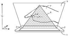
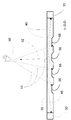
[0015] 도 1은 공중 및 표면 제스처 검출을 위해 구성된 모바일 전자 디바이스의 개략적인 예시의 예를 도시한다.
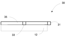
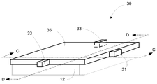
[0016] 도 2a-2d는 저해상도 이미지 데이터를 생성하도록 구성된 디바이스의 예의 다양한 뷰들을 도시한다.
[0017] 도 3은 저해상도 이미지 데이터를 생성하도록 구성된 디바이스의 예를 도시한다.
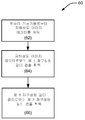
[0018] 도 4는 저해상도 이미지 데이터로부터 고해상도 재구성된 깊이 맵을 획득하기 위한 프로세스를 예시한 흐름도의 예를 도시한다.
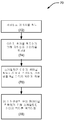
[0019] 도 5는 저해상도 이미지 데이터로부터 제 1 재구성된 깊이 맵을 획득하기 위한 프로세스를 예시한 흐름도의 예를 도시한다.
[0020] 도 6은 제 1 재구성된 깊이 맵으로부터 제 2 재구성된 깊이 맵을 획득하기 위한 프로세스를 예시한 흐름도의 예를 도시한다.
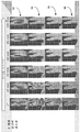
[0021] 도 7은 디바이스의 표면으로부터 다양한 거리들(0 mm, 20 mm, 40 mm, 60 mm, 80 mm 및 100 mm)에서 3-손가락 제스처의 저해상도 이미지들의 예를 도시한다.
[0022] 도 8은 선형 회귀 모델을 획득하기 위한 프로세스를 예시한 흐름도의 예를 도시한다.
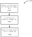
[0023] 도 9는 비선형 회귀 모델을 획득하기 위한 프로세스를 예시한 흐름도의 예를 도시한다.
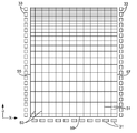
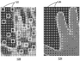
[0024] 도 10은 재구성된 깊이 맵 및 다수의 픽셀 패치들의 개략적인 예시의 예를 도시한다.
[0025] 도 11은 저해상도 이미지 데이터로부터 손가락 끝 위치 정보를 획득하기 위한 프로세스를 예시한 흐름도의 예를 도시한다.
[0026] 도 12는 손가락 끝 검출의 상이한 스테이지들로부터의 이미지들의 예를 도시한다.
[0027] 도 13은 비선형 분류 모델을 획득하기 위한 프로세스를 예시한 흐름도의 예를 도시한다.
[0028] 도 14는 구현에 따른 대화형 디스플레이를 갖는 전자 디바이스의 블록도의 예를 도시한다.
[0029] 다양한 도면들에서 동일한 참조 번호들 및 지정들은 동일한 엘리먼트들을 표시한다.[0015] FIG. 1 illustrates an example of a schematic example of a mobile electronic device configured for air and surface gesture detection.
[0016] Figures 2A-2D illustrate various views of an example of a device configured to generate low resolution image data.
[0017] FIG. 3 illustrates an example of a device configured to generate low resolution image data.
[0018] FIG. 4 illustrates an example of a flow diagram illustrating a process for obtaining a high resolution reconstructed depth map from low resolution image data.
[0019] FIG. 5 illustrates an example of a flow diagram illustrating a process for obtaining a first reconstructed depth map from low resolution image data.
[0020] FIG. 6 shows an example of a flow diagram illustrating a process for obtaining a second reconstructed depth map from a first reconstructed depth map.
[0021] FIG. 7 illustrates an example of low resolution images of a three-finger gesture at various distances (0 mm, 20 mm, 40 mm, 60 mm, 80 mm and 100 mm) from the surface of the device.
[0022] FIG. 8 shows an example of a flow diagram illustrating a process for obtaining a linear regression model.
[0023] FIG. 9 shows an example of a flow diagram illustrating a process for obtaining a nonlinear regression model.
[0024] FIG. 10 shows an example of a schematic example of a reconstructed depth map and a plurality of pixel patches.
[0025] FIG. 11 illustrates an example of a flow chart illustrating a process for obtaining fingertip position information from low resolution image data.
[0026] FIG. 12 illustrates an example of images from different stages of fingertip detection.
[0027] FIG. 13 shows an example of a flow diagram illustrating a process for obtaining a nonlinear classification model.
[0028] Figure 14 shows an example of a block diagram of an electronic device with an interactive display according to an implementation.
[0029] In the various figures, the same reference numerals and designations denote the same elements.
[0030] 후속하는 설명은 본 발명의 혁신적인 양상들을 기술하는 목적들을 위한 특정한 구현들에 관한 것이다. 그러나, 당업자는 본원의 교시가 복수의 상이한 방식들로 적용될 수 있다는 것을 용이하게 인식할 것이다. 기술된 구현들은 (디스플레이에 대한 터치 입력 이외의 목적들로 터치 입력을 사용하는 디바이스를 포함하여) 터치 입력 인터페이스를 사용하는 임의의 디바이스, 장치 또는 시스템에서 구현될 수 있다. 또한, 설명된 구현들이 다양한 전자 디바이스들에 포함되거나 또는 이들과 연관될 수 있는데, 다양한 전자 디바이스들은 가령, 모바일 전화기들, 멀티미디어 인터넷 인에이블 셀룰러 전화기들, 모바일 텔레비전 수신기들, 무선 디바이스들, 스마트폰들, 블루투스® 디바이스들, 개인용 휴대정보 단말기들(PDA들), 무선 전자 메일 수신기들, 핸드-헬드 또는 휴대용 컴퓨터들, 넷북들, 노트북들, 스마트북들, 태블릿들, 프린터들, 복사기들, 스캐너들, 팩시밀리 디바이스들, GPS(global positioning system) 수신기들/네비게이터들, 카메라들, 디지털 미디어 플레이어들(가령, MP3 플레이어들), 캠코더들, 게임 콘솔들, 손목 시계들, 클록들, 계산기들, 텔레비전 모니터들, 평판 패널 디스플레이들, 전자 리딩 디바이스들(즉, e-리더기들), 컴퓨터 모니터들, 자동차 디스플레이들(오도미터(odometer) 및 속도계 디스플레이들 등을 포함함), 쿡핏(cockpit) 제어들 및/또는 디스플레이들, 카메라 뷰 디스플레이들(가령, 차량의 후방 뷰 카메라의 디스플레이), 전자 포토그래프들, 전자 빌보드들 또는 표지판들(signs), 프로젝터들, 건축 구조들, 전자레인지들(microwaves), 냉장고들, 스테레오 시스템들, 카세트 리코더들 또는 플레이어들, DVD 플레이어들, CD 플레이어들, VCR들, 라디오들, 휴대용 메모리 칩들, 세척기들, 건조기들, 세척기/건조기들, 주차요금 계산기들(parking meters) 및 장식(aesthetic) 구조들(가령, 한 조각의 보석류 또는 의류 상의 이미지들의 디스플레이)이지만, 이에 한정되는 것은 아니라는 것이 고찰된다. 따라서, 본 교시들은 도면들 내에 단독으로 도시된 구현들로만 한정되도록 의도되지 않고, 그 대신에 당업자에게 용이하게 명백해질 바와 같이 넓은 적용 가능성을 가진다.[0030] The following description relates to specific implementations for the purposes of describing innovative aspects of the invention. However, those skilled in the art will readily recognize that the teachings herein may be applied in a plurality of different ways. The described implementations may be implemented in any device, device, or system that uses a touch input interface (including devices that use touch input for purposes other than touch input to a display). Also, the described implementations may be included in or associated with various electronic devices, such as mobile telephones, multimedia Internet enabled cellular telephones, mobile television receivers, wireless devices, smart phones, Bluetooth® devices, personal digital assistants (PDAs), wireless e-mail receivers, hand-held or portable computers, netbooks, notebooks, smartbooks, tablets, printers, copiers, Scanners, facsimile devices, global positioning system (GPS) receivers / navigators, cameras, digital media players (e.g. MP3 players), camcorders, game consoles, wristwatches, clocks, , Television monitors, flat panel displays, electronic reading devices (i.e., e-readers), computer monitors, (Including display of odometer and speedometer displays, etc.), cockpit controls and / or displays, camera view displays (e.g., a display of a rear view camera of a vehicle), electronic photographs, Electronic billboards or signs, projectors, architectural structures, microwaves, refrigerators, stereo systems, cassette recorders or players, DVD players, CD players, VCRs, radio But are not limited to, portable memory chips, washes, dryers, washer / dryers, parking meters and aesthetic structures (e.g., display of a piece of jewelry or clothing images) It is not. Accordingly, the present teachings are not intended to be limited to the embodiments shown in the drawings alone, but instead have broad applicability as will be readily apparent to those skilled in the art.
[0031] 본원에 설명된 구현들은 디바이스의 인터페이스에서 또는 그 위에서 물체들을 감지하도록 구성된, 터치 입력 디바이스와 같은 장치들에 관한 것이다. 상기 장치는 검출 영역에서 또는 그 위에서 디바이스와 물체의 상호작용을 검출하고 상호작용을 표시하는 신호들을 출력하도록 구성된 검출기들을 포함한다. 상기 장치들은 신호들로부터 저해상도 이미지 데이터를 획득하고, 저해상도 이미지 데이터로부터 정확한 고해상도 재구성된 깊이 맵을 획득하도록 구성된 프로세서를 포함할 수 있다. 일부 구현들에서, 손가락 끝과 같은 물체들이 식별될 수 있다. 프로세서는 또한 고해상도 깊이 맵들 및 물체 식별로부터 사용자 제스처들의 인스턴스들을 인식하도록 구성될 수 있다. [0031] The implementations described herein relate to devices such as a touch input device configured to sense objects at or above the device's interface. The apparatus includes detectors configured to detect the interaction of the device with the object at or above the detection region and output signals indicative of the interaction. The apparatuses may include a processor configured to obtain low resolution image data from the signals and obtain an accurate high resolution reconstructed depth map from the low resolution image data. In some implementations, objects such as fingertips can be identified. The processor may also be configured to recognize instances of user gestures from high resolution depth maps and object identification.
[0032] 본 개시에 설명된 요지의 특정 구현들은 다음의 잠재적인 이점들 중 하나 이상을 실현하도록 구현될 수 있다. 일부 구현들에서, 사용자 상호작용들의 깊이 맵 정보는 부피가 크고 비싼 하드웨어를 디바이스에 통합하지 않고서 전자 디바이스에 의해 획득될 수 있다. 높은 정확성을 갖는 깊이 맵들이 생성되어, 다수의 손가락 끝 검출 및 제스처 인식을 가능하게 할 수 있다. 정확한 손가락 끝 또는 다른 물체 검출은 낮은 전력 소비를 통해 수행될 수 있다. 일부 구현들에서, 상기 장치들은 대안적인 제스처 인식 기술들에 대해 액세스 불가한 영역들을 비롯하여 검출 영역의 임의의 부분에서 또는 그 위에서 손가락 끝들 또는 제스처들을 검출할 수 있다. 예를 들면, 상기 장치들은 카메라들의 원뿔 모양의 뷰로 인한 카메라-기반 제스처 인식 기술들에 대한 데드 존들인 영역들에서 제스처들을 검출할 수 있다. 또한, 본 개시에 설명된 요지의 구현들은 전자 디바이스의 표면에서뿐만 아니라 전자 디바이스 위에서 손가락 끝들 또는 제스처들을 검출할 수 있다. [0032] Certain implementations of the subject matter described in this disclosure may be implemented to realize one or more of the following potential advantages. In some implementations, depth map information of user interactions may be obtained by the electronic device without incorporating bulky and expensive hardware into the device. Depth maps with high accuracy can be generated, enabling multiple fingertip detection and gesture recognition. Accurate fingertip or other object detection can be performed with low power consumption. In some implementations, the devices may detect fingertips or gestures at or above any portion of the detection area, including areas that are inaccessible to alternative gesture recognition techniques. For example, the devices can detect gestures in areas that are dead zones for camera-based gesture recognition techniques due to conical views of cameras. Further, implementations of the subject matter described in this disclosure can detect fingertips or gestures on electronic devices as well as on the surface of electronic devices.
[0033] 도 1은 공중 및 표면 제스처 검출을 위해 구성된 모바일 전자 디바이스의 개략적인 예시의 예를 도시한다. 모바일 전자 디바이스(1)는 검출 영역(3)을 포함하는 제 1 표면(2)을 포함한다. 도 1의 예에서, 검출 영역(3)은 모바일 전자 디바이스(1)의 대화형 디스플레이이다. 프로세서(미도시)는 사용자 입력들에 적어도 부분적으로 응답하여 대화형 디스플레이의 출력을 제어하도록 구성될 수 있다. 사용자 입력들 중 적어도 일부는 손 또는 손가락, 핸드헬드 물체의 스타일러스 등과 같이 사용자의 부속물(appendage)의 전체 모션을 포함하는 제스처들에 의해 이루어질 수 있다. 도 1의 예에서, 손(7)이 도시된다.[0033] Figure 1 illustrates an example of a schematic illustration of a mobile electronic device configured for air and surface gesture detection. The mobile electronic device (1) comprises a first surface (2) comprising a detection area (3). In the example of Figure 1, the
[0034] 모바일 전자 디바이스(1)는 표면(터치) 및 공중(비접촉) 양자의 제스처 인식을 위해 구성될 수 있다. 도 1의 예에서 영역(5)(부피를 나타냄)은 제스처들을 인식하도록 구성된 모바일 전자 디바이스(1)의 제 1 표면(2) 위에서 z-방향으로 일정 거리를 연장시킨다. 영역(5)은 카메라-기반 제스처 인식에 대한 데드 존인 영역(6)을 포함한다. 따라서, 모바일 전자 디바이스(1)는 현재 카메라-기반 제스처 인식 시스템들이 제스처들을 인식하지 않는 영역(6)에서 제스처들을 인식할 수 있다. 손 또는 다른 물체의 형상 및 깊이 정보는 제스처들을 인식하기 위해 표현 어휘(expression vocabulary)와 비교될 수 있다. [0034] The mobile
[0035] 본원에 설명된 장치 및 방법들은, 예를 들면, 채용된 센서 시스템에 의존하여 그리고 인식 또는 추적되는 특징에 의존하여 (예를 들면, 모바일 전자 디바이스의 대화형 디스플레이의) 표면으로부터 최대 약 20-40 cm 또는 심지어 그보다 더 큰 z-방향 인식 거리 또는 깊이를 가질 수 있다. 예를 들면, 손가락 끝 검출 및 (손가락 끝-기반 제스처들에 대한) 추적에서, 최대 약 10-15 cm 또는 심지어 그보다 더 큰 z-방향 인식 거리들 또는 깊이들이 가능하다. 예를 들면, 손-스와이프 제스처에 대한 전체 손바닥 또는 손의 검출 및 추적에 대해, 최대 30 cm 또는 심지어 그보다 더 큰 z-방향 인식 거리들 또는 깊이들이 가능하다. 도 1을 참조하여 앞서 설명된 바와 같이, 장치 및 방법들은 0 cm(표면에서)로부터 인식 거리까지 디바이스 위에서 전체 볼륨의 임의의 물체를 인식할 수 있다. [0035] The apparatus and methods described herein may be used, for example, depending on the sensor system employed and depending on the feature being recognized or tracked (eg, in the interactive display of a mobile electronic device) Direction recognition distance or depth of 20-40 cm or even greater. For example, in fingertip detection and tracking (for fingertip-based gestures), z-directional recognition distances or depths of up to about 10-15 cm or even larger are possible. For example, z-directional recognition distances or depths of up to 30 cm, or even larger, are possible for the detection and tracking of the entire palm or hand for a hand-swipe gesture. As described above with reference to Fig. 1, the apparatus and methods can recognize any object of the entire volume on the device from the 0 cm (at the surface) to the recognition distance.
[0036] 그러나, 장치 및 방법들이, 예를 들면, PCT 시스템들을 비롯하여, 임의의 z-방향 능력들을 갖는 센서 시스템들에서 채용될 수 있다는 것이 주목되어야 한다. 또한, 구현들은 표면-전용 센서 시스템들에서 채용될 수 있다. [0036] It should be noted, however, that the apparatus and methods may be employed in sensor systems having any z-directional capabilities, including, for example, PCT systems. Also, implementations may be employed in surface-only sensor systems.
[0037] 본원에 개시된 장치 및 방법들은 저해상도 이미지 데이터를 사용한다. 저해상도 이미지 데이터는 임의의 특정 센서 데이터로 제한되지 않지만, 포토다이오드들, 포토트랜지스터들, CCD(charge coupled device) 어레이들, CMOS(complementary metal oxide semiconductor) 어레이 또는 검출된 가시선, 적외선(IR) 및/또는 자외선(UV) 광의 특성을 나타내는 신호를 출력하도록 동작 가능한 임의의 적절한 디바이스들로부터 생성된 이미지 데이터를 포함할 수 있다. 또한, 저해상도 이미지 데이터는 일부 구현들에서 커패시턴스 감지 메커니즘들을 비롯하여 비-광 센서들로부터 생성될 수 있다. 일부 구현들에서, 센서 시스템은 검출 영역의 하나 이상의 에지들을 따른 센서들을 갖는 평면 검출 영역을 포함한다. 그러한 시스템들의 예들이 도 2a-2d 및 3에 관련하여 아래에 설명된다.[0037] The apparatus and methods disclosed herein employ low resolution image data. Low resolution image data is not limited to any particular sensor data, but may include photodiodes, phototransistors, charge coupled device arrays, complementary metal oxide semiconductor (CMOS) arrays or detected line of sight, infrared (IR) Or image data generated from any suitable device operable to output a signal indicative of the characteristics of ultraviolet (UV) light. In addition, low resolution image data may be generated from non-light sensors, including capacitance sensing mechanisms in some implementations. In some implementations, the sensor system includes a planar detection area having sensors along one or more edges of the detection area. Examples of such systems are described below with respect to Figures 2a-2d and 3.
[0038] 깊이 맵들을 재구성될 수 있는 저해상도 이미지 데이터는 깊이 맵 이미지 데이터가 아니라는 것이 주목되어야 한다. 일부 깊이 정보가 데이터에서 암시적일 수 있지만(예를 들면, 신호 강도가 표면으로부터의 거리와 상관될 수 있음), 저해상도 이미지 데이터는 거리 정보 자체를 포함하지는 않는다. 이로써, 본원에 개시된 방법들은, 깊이 맵 데이터(예를 들면, 단안(monocular) 이미지로부터 생성된 초기 깊이 맵)가 양방향 필터링(bilateral filtering)과 같은 기술들을 사용하여 개선되는 다양한 방법들과 별개이다. 또한, 일부 구현들에서, 저해상도 이미지 데이터의 해상도는, 양방향 필터링 기술이 사용할 수 있는 것보다 상당히 더 낮을 수 있다. 그러한 기술은, 예를 들면, 적어도 100 x 100의 해상도를 갖는 이미지를 채용할 수 있다. 본원에 개시된 방법들 및 장치가 100 x 100 또는 그보다 더 높은 해상도 이미지로부터 재구성된 깊이 맵을 획득하도록 구현될 수 있지만, 일부 구현들에서, 본원에 설명된 장치 및 방법들에서 사용되는 저해상도 이미지 데이터는 50 x 50 미만 또는 심지어 30 x 30 미만일 수 있다.[0038] It should be noted that the low-resolution image data that can be reconstructed from depth maps is not depth map image data. Although some depth information may be implicit in the data (e.g., the signal strength may be correlated with the distance from the surface), the low resolution image data does not include the distance information itself. As such, the methods disclosed herein are distinct from the various methods by which depth map data (e.g., initial depth maps generated from monocular images) are improved using techniques such as bilateral filtering. Also, in some implementations, the resolution of the low-resolution image data may be significantly lower than that available for bidirectional filtering techniques. Such a technique may employ, for example, an image having a resolution of at least 100 x 100. Although the methods and apparatus described herein can be implemented to obtain a reconstructed depth map from a 100 x 100 or higher resolution image, in some implementations, the low resolution image data used in the apparatus and methods described herein Less than 50 x 50, or even less than 30 x 30.
[0039] 획득된 이미지의 해상도는 디바이스의 크기 및 종횡비에 의존할 수 있다. 예를 들면, 약 1.8의 종횡비를 갖는 디바이스에서, 저해상도 이미지의 해상도는 일부 구현들에서 100 x 100 미만, 100 x 55 미만, 60 x 33 미만 또는 40 x 22 미만일 수 있다.[0039] The resolution of the acquired image may depend on the size and aspect ratio of the device. For example, in a device having an aspect ratio of about 1.8, the resolution of a low resolution image may be less than 100 x 100, less than 100 x 55, less than 60 x 33, or less than 40 x 22 in some implementations.
[0040] 해상도는 또한 피치, 즉, 픽셀들 사이의 중심 대 중심 거리에 관련하여 특징화될 수 있고, 더 큰 피치는 더 작은 해상도에 대응한다. 예를 들면, 111 mm x 51 mm의 치수들을 갖는 모바일 폰과 같은 디바이스에 대해, 3 mm의 피치는 37 x 17의 해상도에 대응한다. 적절한 피치는 인식될 물체의 크기에 기초하여 선택될 수 있다. 예를 들면, 손가락 인식에서, 5 mm의 피치가 적절할 수 있다. 3 mm, 1 mm, 0.5 mm 또는 그 미만의 피치는, 예를 들면, 스타일러스의 검출을 위해 적절할 수 있다. [0040] The resolution can also be characterized in terms of pitch, ie, the center-to-center distance between pixels, with a larger pitch corresponding to a smaller resolution. For example, for a device such as a mobile phone having dimensions of 111 mm x 51 mm, a pitch of 3 mm corresponds to a resolution of 37 x 17. A suitable pitch can be selected based on the size of the object to be recognized. For example, in finger recognition, a pitch of 5 mm may be appropriate. Pitches of 3 mm, 1 mm, 0.5 mm or less may be suitable for detection of, for example, a stylus.
[0041] 본원에 개시된 방법들 및 장치가 앞서 설명된 것보다 더 높은 해상도들 및 더 작은 피치들을 갖는 저해상도 데이터를 사용하여 구현될 수 있다는 것이 이해될 것이다. 예를 들면, 더 큰 스크린들을 갖는 디바이스들은 200 x 200 또는 그 초과의 해상도들을 가질 수 있다. 임의의 해상도 또는 피치에 대해, 본원에 개시된 방법들 및 장치는 더 높은 해상도 재구성된 깊이 맵들을 획득하도록 구현될 수 있다. [0041] It will be appreciated that the methods and apparatus disclosed herein can be implemented using low resolution data with higher resolutions and smaller pitches than those previously described. For example, devices with larger screens may have resolutions of 200 x 200 or greater. For any resolution or pitch, the methods and apparatus disclosed herein may be implemented to obtain higher resolution reconstructed depth maps.
[0042] 도 2a-2d는 저해상도 이미지 데이터를 생성하도록 구성된 디바이스의 예를 도시한다. 도 2a 및 도 2b는 구현에 따른 광 가이드(35), 발광 소스(31) 및 광 센서들(33)을 포함하는 배열(30)의 정면도 및 사시도를 각각 도시한다. 광 가이드(35)의 측면 또는 에지의 일부분을 따라서만 예시되지만, 소스가 광 가이드(35)의 에지를 따라 배치된 발광 소스들(31)의 어레이를 포함할 수 있다는 것이 이해된다. 도 2c는 도 2b의 C-C에 평행하는 라인으로부터 보이는 광 가이드의 단면의 예를 도시하고, 도 2d는 도 2b의 D-D에 평행하는 라인으로부터 보이는 광 가이드의 단면의 예를 도시한다. 도 2a 및 2b를 참조하면, 광 가이드(35)는 대화형 디스플레이(12)의 전방 표면 위에 배치되고 실질적으로 이에 평행할 수 있다. 예시된 구현에서, 광 가이드(35)의 둘레는 대화형 디스플레이(12)의 둘레와 실질적으로 같은 공간을 차지한다. 다양한 구현들에 따라, 광 가이드(35)의 둘레는 대화형 디스플레이(12)의 둘레와 동일한 공간을 차지하거나 그보다 더 크고 완전히 둘러쌀 수 있다. 발광 소스(31) 및 광 센서들(33)은 광 가이드(35)의 주변에 근접하게 그리고 외부에 배치될 수 있다. 발광 소스(31)는 광 가이드(35)의 입력과 광학적으로 커플링될 수 있고, 대화형 디스플레이(12)의 전방 표면과 평행하는 상당한 컴포넌트를 갖는 방향으로 광 가이드(35)를 향해 광을 방출하도록 구성될 수 있다. 다른 구현들에서, 복수의 발광 소스들(31)은 광 가이드(35)의 에지를 따라 배치되고, 이들 각각은 짧은 듀레이션 동안에 광 가이드에서 열형(column-like) 또는 행형(row-like) 영역을 순차적으로 조명한다. 광 센서들(33)은 광 가이드(35)의 출력과 광학적으로 커플링될 수 있고, 대화형 디스플레이(12)의 전방 표면과 평행하는 상당한 컴포넌트를 갖는 방향으로 광 가이드(35)로부터 광 출력을 검출하도록 구성될 수 있다. [0042] Figures 2A-2D illustrate examples of devices configured to generate low resolution image data. 2A and 2B show a front view and a perspective view respectively of an
[0043] 예시된 구현에서, 2 개의 광 센서들(33)이 제공되지만, 다른 구현들에서, 도 3을 참조하여 아래에 추가로 논의되는 바와 같이 더 많은 광 센서들이 제공될 수 있다. 광 센서들(33)은 포토다이오드들, 포토트랜지스터들, CCD(charge coupled device) 어레이들, CMOS(complementary metal oxide semiconductor) 어레이 또는 검출된 가시선, 적외선(IR) 및/또는 자외선(UV) 광의 특성을 나타내는 신호를 출력하도록 동작 가능한 임의의 적절한 디바이스들과 같은 감광성 엘리먼트들을 포함할 수 있다. 광 센서들(33)은 검출된 광의 하나 이상의 특성들을 나타내는 신호들을 출력할 수 있다. 예를 들면, 특성들은 강도, 방향성, 주파수, 진폭, 진폭 변조 및/또는 다른 속성들을 포함할 수 있다. [0043] In the illustrated implementation, two
[0044] 예시된 구현에서, 광 센서들(33)은 광 가이드(35)의 주변에 배치된다. 그러나, 대안적인 구성들은 본 개시의 고차 내에 있다. 예를 들면, 광 센서들(33)은 광 가이드(35)보다 원격에 있을 수 있고, 이 경우에 광 센서들(33)에 의해 검출된 광은, 예를 들면, 하나 이상의 광섬유들과 같은 부가적인 광학 엘리먼트들에 의해 광 가이드(35)로부터 송신될 수 있다. [0044] In the illustrated implementation, the
[0045] 구현에서, 발광 소스(31)는 주로 적외선 광을 방출하도록 구성된 하나 이상의 발광 다이오드들(LED)일 수 있다. 그러나, 임의의 타입의 광원이 사용될 수 있다. 예를 들면, 발광 소스(31)는 하나 이상의 OLED들(organic light emitting devices), 레이저들(예를 들면, 다이오드 레이저들 또는 다른 레이저 소스들), 핫 또는 콜드 캐소드 형광 램프들, 백열 또는 할로겐 광 소스들을 포함할 수 있다. 예시된 구현에서, 발광 소스(31)는 광 가이드(35) 주변에 배치된다. 그러나, 대안적인 구성들은 본 개시의 고찰 내에 있다. 예를 들면, 발광 소스(31)는 광 가이드(35)로부터 원격에 있을 수 있고, 발광 소스(31)에 의해 생성된 광은, 예를 들면, 하나 이상의 광 섬유들, 반사기들 등과 같은 부가적인 광학 엘리먼트들에 의해 광 가이드(35)로 전송될 수 있다. 예시된 구현에서, 하나의 발광 소스(31)가 제공되지만, 다른 구현들에서 2 개 이상의 발광 소스들이 제공될 수 있다.[0045] In an implementation, the
[0046] 도 2c는 도 2b의 C-C에 평행하는 라인으로부터 보이는 광 가이드(35)의 단면의 예를 도시한다. 예시의 명확성을 위해, 대화형 디스플레이(12)가 도 2c로부터 생략된다. 광 가이드(35)는 대화형 디스플레이(12)의 전방 표면 상에 또는 위에 그리고 근접하게 배치된 실질적으로 투명하고, 비교적 얇은 오버레이를 포함할 수 있다. 일 구현에서, 예를 들면, 광 가이드(35)는, 수십 또는 수백의 평방 센티미터의 근사치 범위의 평면 영역을 가지면서, 대략 0.5 mm 두께일 수 있다. 광 가이드(35)는 실질적으로 평평하고 평행한 표면들일 수 있는 전방 표면(37) 및 후방 표면(39)을 갖는, 유리 또는 플라스틱과 같은 투명한 재료로 구성된 얇은 플레이트를 포함할 수 있다. [0046] FIG. 2C shows an example of a section of a
[0047] 투명한 재료는 1보다 더 큰 굴절률을 가질 수 있다. 예를 들면, 굴절률은 약 1.4 내지 1.6 범위에 있을 수 있다. 투명한 재료의 굴절률은, 'α'미만의 각도로 전방 표면(37)을 교차하는 광선이 전방 표면(37)을 통과하지만 'α'를 초과하는 전방 표면(37)에 관련된 입사각을 갖는 광선이 TIR(total internal reflection)을 겪도록 하는, 전방 표면(37)의 법선(normal)에 관련하여 임계각 'α'을 결정한다.[0047] The transparent material may have a refractive index greater than one. For example, the index of refraction may range from about 1.4 to 1.6. The refractive index of the transparent material is such that the ray of light having an angle of incidence associated with the
[0048] 예시된 구현에서, 광 가이드(35)는 발광 소스(31)로부터 수신된 방출된 광(41)을 전방 표면(37)에 직교하는 상당한 컴포넌트를 갖는 방향으로 반사하는 광 터닝 배열을 포함한다. 더 구체적으로, 반사된 광(42)의 적어도 상당한 부분은 임계각 'α' 미만인 법선에 대한 각도로 전방 표면(37)을 교차한다. 결과적으로, 그러한 반사된 광(42)은 TIR을 겪지 않지만, 대신에 전방 표면(37)을 통해 투과될 수 있다. 반사된 광(42)이 매우 다양한 각도들로 전방 표면(37)을 통해 투과될 수 있다는 것이 인지될 것이다.In the illustrated implementation, the
[0049] 구현에서, 광 가이드는 다수의 반사성 미세구조들(36)을 포함하는 광-터닝 배열을 가질 수 있다. 미세구조들(36) 모두는 동일하거나, 다양한 구현들에서 상이한 형상들, 크기들, 구조들 등을 가질 수 있다. 미세구조들(36)은, 반사된 광(42)의 적어도 상당한 부분이 임계각 'α' 미만인 법선에 대한 각도로 전방 표면(37)을 교차하도록 방출된 광(41)을 재지향할 수 있다. [0049] In an implementation, the light guide may have a light-turning arrangement comprising a plurality of
[0050] 도 2d는 도 2b의 D-D에 평행하는 라인으로부터 보이는 광 가이드의 단면의 예를 도시한다. 예시의 명확성을 위해, 대화형 디스플레이(12)가 도 2d로부터 생략된다. 도 2d에 예시된 바와 같이, 물체(50)가 반사된 광(42)과 상호작용할 때, 상호작용으로부터 발생한 산란된 광(44)은 광 가이드(35)를 향해 지향될 수 있다. 광 가이드(35)는, 예시된 바와 같이, 다수의 반사성 미세구조들(66)을 포함하는 광-터닝 배열을 포함할 수 있다. 반사성 미세구조들(66)은 반사성 미세구조들(36)과 유사하게 구성되거나 동일한 물리적 엘리먼트들일 수 있지만, 이것이 반드시 그렇지는 않다. 일부 구현들에서, 반사성 미세구조들(66)은 광 센서들(33)을 향해 광을 반사하도록 구성되고, 한편 반사성 미세구조들(36)은 광원(31)으로부터 광을 반사하고 광 가이드 밖으로 반사된 광을 배출하도록 구성된다. 반사성 미세구조들(66) 및 반사성 미세구조들(36)이 특정 배향을 갖는다면, 반사성 미세구조들(66) 및 반사성 미세구조들(36)이 일부 구현들에서 일반적으로 서로 수직할 수 있다는 것이 이해된다. FIG. 2D shows an example of a section of a light guide viewed from a line parallel to D-D of FIG. 2B. For clarity of illustration, the
[0051] 도 2d에 예시된 바와 같이, 물체(50)가 반사된 광(42)과 상호작용할 때, 상호작용으로부터 발생한 산란된 광(44)은 광 가이드(35)를 향해 지향될 수 있다. 광 가이드(35)는 산란된 광(44)을 수집하도록 구성될 수 있다. 광 가이드(35)는 광 가이드(35)에 의해 수집된 산란된 광(44)을 광 센서들(33) 중 하나 이상을 향해 재지향하는 광-터닝 배열을 포함한다. 재지향된 수집된 산란된 광(46)은 대화형 디스플레이(12)의 전방 표면에 평행하는 상당한 컴포넌트를 갖는 방향으로 터닝될 수 있다. 더 구체적으로, 재지향된 수집된 산란된 광(46)의 적어도 상당한 부분은 임계각 'α'보다 큰 법선에 대한 각도로만 전방 표면(37) 및 후방 표면(39)을 교차하고, 따라서 TIR을 겪는다. 결과적으로, 그러한 재지향된 수집된 산란된 광(46)은 전방 표면(37) 또는 후방 표면(39)을 통과하지 않고, 대신에 광 센서들(33) 중 하나 이상에 도달한다. 광 센서들(33) 각각은 재지향된 수집된 산란된 광(46)의 하나 이상의 특성들을 검출하고, 검출된 특성들을 나타내는 신호를 프로세서로 출력하도록 구성될 수 있다. 예를 들면, 특성들은 강도, 방향성, 주파수, 진폭, 진폭 변조 및/또는 다른 속성들을 포함할 수 있다. As illustrated in FIG. 2 d, when the
[0052] 도 3은 저해상도 이미지 데이터를 생성하도록 구성된 디바이스의 다른 예를 도시한다. 도 3의 예에서 디바이스는 광 가이드(35), 광 가이드(35)의 대향 에지들(55 및 57)을 따라 분포된 복수의 광 센서들(33), 및 에지들(55 및 57)에 직교하는 광 가이드의 에지(59)를 따라 분포된 복수의 광원들(31)을 포함한다. 방출 트로프들(emission troughs)(51) 및 수집 트로프들(53)이 또한 도 3의 예에 도시된다. 방출 트로프들(51)은, 광원들(31)로부터의 광을 광 가이드(35)의 전방 표면을 통해 지향할 수 있는 도 2c에 도시된 반사성 미세구조들(36)과 같은 광-터닝 특징부들이다. 수집 트로프들(53)은, 광을 물체로부터 광 센서들(33)로 지향할 수 있는 도 2d에 도시된 반사성 미세구조들(66)과 같은 광 터닝 특징부들이다. 도 3의 예에서, 방출 트로프들(51)은, 광원들(51)에 의해 방출된 광이 감쇠를 처리하기 위해 감쇠할 때 트로프들의 간격이 더 가깝도록 이격된다. 일부 구현들에서, 광원들(31)은 x-좌표 정보를 순차적으로 제공하도록 순차적으로 턴 온될 수 있고, 대응하는 y-좌표 정보는 각각의 y-좌표에서 광 센서들(33)의 쌍에 의해 제공된다. 본원에 제공된 본 개시를 통해 구현될 수 있는 시간-순차적인 측정들을 채용하는 장치 및 방법들은 2013년 10월 10일에 출원되고 인용에 의해 본원에 통합된 미국 특허 출원 제 14/051,044 호, "Infrared Touch And Hover System Using Time-Sequential Measurements"에 기재된다. 도 3의 예에서, 21 x 11의 해상도를 제공하기 위해 에지들(55 및 57) 각각을 따른 21 개의 광 센서들(33) 및 에지(59)를 따른 11 개의 광원들(31)이 존재한다. [0052] FIG. 3 shows another example of a device configured to generate low-resolution image data. 3, the device includes a plurality of
[0053] 도 4는 저해상도 이미지 데이터로부터 고해상도 재구성된 깊이 맵을 획득하기 위한 프로세스를 예시한 흐름도의 예를 도시한다. 일부 구현들에 따른 프로세스의 개요가 도 4에 주어지고, 특정 구현들의 예들이 또한 도 5 및 6을 참조하여 아래에 설명된다. 프로세스(60)는 복수의 검출기들로부터 저해상도 이미지 데이터를 획득하는 블록(62)에서 시작한다. 본원에 설명된 장치 및 방법들은 저해상도 이미지 데이터를 생성할 수 있는 임의의 시스템에서 구현될 수 있다. 도 2a-2d 및 3을 참조하여 위에 설명된 디바이스들은 그러한 시스템들의 예들이다. 2012년 5월 23일에 출원된 미국 특허 출원 제 13/480,377 호, "Full Range Gesture System", 2013년 10월 10일에 출원된 미국 특허 출원 제 14/051044 호, "Infrared Touch And Hover System Using Time-Sequential Measurements"에 추가의 예들이 제공되고, 상기 출원들 둘 모두는 전체 내용이 인용에 의해 본원에 통합된다. [0053] FIG. 4 illustrates an example of a flow diagram illustrating a process for obtaining a high-resolution reconstructed depth map from low-resolution image data. An overview of the process according to some implementations is given in FIG. 4, and examples of specific implementations are also described below with reference to FIGS. 5 and 6. FIG.
[0054] 일부 구현들에서, 저해상도 이미지 데이터는 이미지 내의 x-y 위치들에서 이미지 특성들을 식별하는 정보를 포함할 수 있다. 도 7은 디바이스의 표면으로부터 다양한 거리들(0 mm, 20 mm, 40 mm, 60 mm, 80 mm 및 100 mm)에서 3-손가락 제스처의 저해상도 이미지들(92)의 예를 도시한다. 물체 깊이는 컬러(그레이 스케일 이미지에서 더 어두운 그리고 더 밝은 톤들로서 보여짐)에 의해 표현된다. 도 7의 예에서, 저해상도 이미지들은 21 x 11의 해상도를 갖는다. [0054] In some implementations, the low resolution image data may include information identifying image characteristics at x-y locations within the image. 7 shows an example of
[0055] 프로세스(60)는 저해상도 이미지 데이터로부터 제 1 재구성된 깊이 맵을 획득하는 블록(64)에서 계속된다. 재구성된 깊이 맵은 디바이스의 표면으로부터 물체의 표면들의 거리에 관련된 정보를 포함한다. 블록(64)은 저해상도 이미지 데이터로부터 주목할 만한 물체 구조를 업스케일링 및 리트리브할 수 있고, 제 1 재구성된 깊이 맵은 저해상도 이미지 데이터에 대응하는 저해상도 이미지보다 더 높은 해상도를 갖는다. 일부 구현들에서, 제 1 재구성된 깊이 맵은 최종 원하는 해상도에 대응하는 해상도를 갖는다. 다양한 구현들에 따라, 제 1 재구성된 깊이 맵은 저해상도 이미지보다 적어도 약 1.5 배 내지 적어도 약 6 배 더 높은 해상도를 가질 수 있다. 예를 들면, 제 1 재구성된 깊이 맵은 저해상도 이미지보다 적어도 약 3 또는 4배보다 더 높은 해상도를 가질 수 있다. 블록(64)은 순차적인 저해상도 이미지들에 대응하는 재구성된 깊이 맵들의 세트를 획득하는 것을 수반할 수 있다. [0055] The
[0056] 블록(64)은 블록(62)에서 획득된 저해상도 이미지 데이터에 학습된 회귀 모델을 적용하는 것을 수반할 수 있다. 도 5를 참조하여 아래에 추가로 설명되는 바와 같이, 일부 구현들에서, 학습된 선형 회귀 모델이 적용된다. 아래에 추가로 또한 설명되는 도 8은 블록(64)에서 적용될 수 있는 선형 회귀 모델을 학습하는 것의 예를 제공한다. 도 7은 저해상도 이미지들(92)에 대응하는 제 1 재구성된 깊이 맵들(94)의 예를 도시한다. 저해상도 이미지들(92)을 생성하는데 사용되는 저해상도 이미지 데이터로부터 재구성된 제 1 재구성된 깊이 맵들(94)은 131 x 61의 해상도를 갖는다. [0056]
[0057] 도 4로 복귀하면, 프로세스는 제 1 재구성된 깊이 맵으로부터 제 2 재구성된 깊이 맵을 획득함으로써 블록(66)에서 계속된다. 제 2 재구성된 깊이 맵은 개선된 경계들 및 물체 내의 더 적은 잡음을 제공할 수 있다. 블록(66)은 제 2 재구성된 깊이 맵을 획득하기 위해 트레이닝된 비선형 회귀 모델을 제 1 재구성된 깊이 맵에 적용하는 것을 수반할 수 있다. 예를 들면, 랜덤 포레스트 모델, 뉴럴 네트워크 모델, 딥 러닝 모델, 서포트 벡터 머신 모델 또는 다른 적절한 모델이 적용될 수 있다. 도 6은 트레이닝된 비선형 회귀 모델을 적용하는 것의 예를 제공하고, 도 9는 블록(66)에 적용될 수 있는 비선형 회귀 모델을 트레이닝하는 것의 예를 제공한다. 블록(64)에서와 같이, 블록(66)은 순차적인 저해상도 이미지들에 대응하는 재구성된 깊이 맵들의 세트를 획득하는 것을 수반할 수 있다. [0057] Returning to FIG. 4, the process continues at
[0058] 일부 구현들에서, 비교적 간단한 트레이닝된 비선형 회귀 모델이 적용될 수 있다. 일 예에서, 뉴럴 네트워크 회귀의 입력 계층은, 입력 계층의 크기가 25 이도록 제 1 재구성된 깊이 맵으로부터 5 x 5 패치를 포함할 수 있다. 크기 5의 은닉된 계층은 단일 깊이 맵 값을 출력하는데 사용될 수 있다. [0058] In some implementations, a relatively simple trained nonlinear regression model may be applied. In one example, the input layer of the neural network regression may include a 5 x 5 patch from the first reconstructed depth map such that the size of the input layer is 25. A hidden layer of
[0059] 도 7은 제 1 재구성된 깊이 맵들(94)로부터 재구성된, 디바이스의 표면으로부터 다양한 거리들의 제 2 재구성된 깊이 맵들(96)의 예를 도시한다. 제 1 재구성된 깊이 맵들(96)은 제 1 재구성된 깊이 맵들(94)과 동일한 131 x 61의 해상도를 갖지만 개선된 정확성을 갖는다. 이것은 제 1 재구성된 깊이 맵들(94) 및 제 2 재구성된 깊이 맵들(96)과 타임 오브 플라이트 카메라로부터 생성된 지상 검증 자료(ground truth) 깊이 맵들(98)을 비교함으로써 보여질 수 있다. 제 1 재구성된 깊이 맵들(94)은 관측된 손 내의 깊이 값들에서 약간의 부정확한 변동으로 제 2 재구성된 깊이 맵들(96)보다 덜 균일하다. 비교로부터 볼 수 있듯이, 제 2 재구성된 깊이 맵들(96)은 제 1 재구성된 깊이 맵들(94)보다 지상 검증 자료 깊이 맵들(98)과 더 유사하다. 프로세스(60)는 정확한 재구성된 깊이 맵들을 생성하기 위해 비싸고, 부피가 크고 전력 소비 하드웨어 없이 저품질 이미지들의 결점들을 효율적으로 극복할 수 있다. 도 5는 저해상도 이미지 데이터로부터 제 1 재구성된 깊이 맵을 획득하기 위한 프로세스를 예시한 흐름도의 예를 도시한다. 프로세스(70)는 입력으로서 저해상도 이미지를 획득하는 블록(72)에서 시작한다. 저해상도 이미지들의 예들이 앞서 설명된 도 7에 도시된다. 프로세스(70)는 이미지 벡터를 획득하기 위해 저해상도 이미지(74)를 벡터화하는 블록(74)에서 계속될 수 있다. 이미지 벡터는 입력 이미지에 대한 검출기로부터 수신된 신호들을 나타내는 값들(예를 들면, 포토다이오드들로부터의 전류)을 포함한다. 일부 구현들에서, 예를 들면, 저해상도 이미지 데이터가 벡터 형태로 제공되면, 블록들(72 및 74)이 수행되지 않을 수 있다. 프로세스(70)는 스케일링 가중 행렬 W를 이미지 벡터에 적용하는 블록(76)에서 계속된다. 스케일링 가중 행렬 W은, 아래에 설명되는 트레이닝으로부터 획득된 타임-오브-플라이트 카메라 데이터로부터 생성된 고해상도 깊이 맵들과 저해상도 이미지들 사이의 학습된 선형 관계를 나타낸다. 결과는 스케일링된 이미지 벡터이다. 스케일링된 이미지 벡터는 그레이 스케일 깊이 맵 값들을 나타내는 0 내지 1의 값들을 포함할 수 있다. 프로세스(70)는 제 1 재구성된 깊이 맵(R1)을 획득하기 위해 스케일링된 이미지 벡터를 역벡터화함으로써 블록(78)에서 계속될 수 있다. 블록(78)은 순차적인 저해상도 이미지들에 대응하는 제 1 재구성된 깊이 맵들의 세트를 획득하는 것을 수반할 수 있다. 제 1 재구성된 깊이 맵들의 예들은 앞서 설명된 바와 같이 도 7에 도시된다. [0059] FIG. 7 illustrates an example of second reconstructed depth maps 96 of various distances from the surface of the device reconstructed from the first reconstructed depth maps 94. The first reconstructed depth maps 96 have the same 131 x 61 resolution as the first reconstructed depth maps 94 but have improved accuracy. This can be seen by comparing the first reconstructed depth maps 94 and the second reconstructed depth maps 96 with the ground truth depth maps 98 generated from the time of flight camera. The first reconstructed depth maps 94 are less uniform than the second reconstructed depth maps 96 with some inaccurate variation in depth values within the observed hand. As can be seen from the comparison, the second reconstructed depth maps 96 are more similar to the ground validation data depth maps 98 than the first reconstructed depth maps 94.
[0060] 도 6은 제 1 재구성된 깊이 맵으로부터 제 2 재구성된 깊이 맵을 획득하기 위한 프로세스를 예시한 흐름도의 예를 도시한다. 앞서 설명된 바와 같이, 이것은 비선형 회귀 모델을 제 1 재구성된 깊이 맵을 적용하는 것을 수반할 수 있다. 비선형 회귀 모델은 앞서 설명된 바와 같이 획득될 수 있다. 프로세스(80)는 제 1 재구성된 깊이 맵의 픽셀 n에 대한 특징을 추출함으로써 블록(82)에서 시작된다. 일부 구현들에서, 비선형 회귀 모델의 특징들은 다중-픽셀 패치들일 수 있다. 예를 들면, 특징들은 7 x 7 픽셀 패치들일 수 있다. 다중-픽셀 패치는 픽셀 n에 대해 중앙화될 수 있다. 프로세스(80)는 픽셀 n에 대한 회귀값을 결정하기 위해 트레이닝된 비선형 모델을 픽셀 n에 적용하는 블록(84)에서 계속된다. 프로세스(80)는 제 1 재구성된 깊이 맵의 모든 픽셀들에 걸쳐 블록(82 및 84)을 수행함으로써 블록(86)에서 계속된다. 일부 구현들에서, 블록(86)은, 다른 기술들이 또한 적용될 수 있다고 이해될 것이지만, 슬라이딩 윈도우 또는 래스터 스캐닝 기술을 수반할 수 있다. 제 1 재구성된 깊이 맵의 모든 픽셀들에 걸쳐 블록들(82 및 84)을 픽셀마다 적용하는 것은 제 1 재구성된 깊이 맵과 동일한 해상도의 개선된 깊이 맵을 발생시킬 수 있다. 프로세스(80)는 블록(84)에서 획득된 회귀 값들로부터 제 2 재구성된 깊이 맵을 획득함으로써 블록(88)에서 계속된다. 블록(88)은 순차적인 저해상도 이미지들에 대응하는 제 2 재구성된 깊이 맵들의 세트를 획득하는 것을 수반할 수 있다. 제 2 재구성된 깊이 맵들의 예들은 앞서 설명된 바와 같이 도 7에 도시된다. [0060] FIG. 6 illustrates an example of a flow diagram illustrating a process for obtaining a second reconstructed depth map from a first reconstructed depth map. As described above, this may involve applying a non-linear regression model to the first reconstructed depth map. The nonlinear regression model can be obtained as described above. The
[0061] 도 4-6을 참조하여 앞서 설명된 프로세스들은 학습 또는 트레이닝된 선형 및 비선형 회귀 모델들을 적용하는 것을 수반한다. 일부 구현들에서, 모델들은 물체 및 물체의 대응하는 센서 이미지들의 깊이 맵들의 쌍들을 포함하는 트레이닝 세트를 사용하여 학습 또는 트레이닝될 수 있다. 트레이닝 세트 데이터는, 병진 위치들, 회전 배향들 및 깊이들(센서 표면으로부터의 거리들)을 비롯하여, 다양한 제스처들 및 위치들의 물체에 대한 저해상도 센서 이미지들 및 깊이 맵들을 획득함으로써 획득될 수 있다. 예를 들면, 트레이닝 세트 데이터는 손들의 깊이 맵들 및 다양한 제스처들, 병진들, 회전들 및 깊이들의 손의 대응하는 센서 이미지들을 포함할 수 있다. [0061] The processes described above with reference to Figures 4-6 involve applying linear or non-linear regression models that are either learned or trained. In some implementations, the models may be learned or trained using a training set that includes pairs of depth maps of the object and corresponding sensor images of the object. The training set data can be obtained by obtaining low resolution sensor images and depth maps for objects of various gestures and positions, including translation positions, rotational orientations and depths (distances from the sensor surface). For example, the training set data may include corresponding sensor images of hands of depth maps and hands of various gestures, translations, rotations, and depths.
[0062] 도 8은 선형 회귀 모델을 획득하기 위한 프로세스를 예시한 흐름도의 예를 도시한다. 획득된 선형 회귀 모델은 본원에 설명된 장치의 동작에 적용될 수 있다. 프로세스(100)는 다수의 물체 제스처들 및 위치들에 대한 고해상도 깊이 맵들(지상 검증 자료) 및 저해상도 이미지들의 쌍들의 (크기 m의) 트레이닝 세트 데이터를 획득함으로써 블록(102)에서 시작된다. 깊이 맵들은 타임-오브-플라이트 카메라, 광학 모델링 또는 이들의 조합과 같은 임의의 적절한 방법에 의해 획득될 수 있다. 센서 이미지들은 디바이스 자체(가령, 도 3의 디바이스, 여기서 각각의 저해상도 이미지는 값들의 행렬이고, 그러한 값들은, 예를 들면, 주어진 x-좌표에서의 광원이 순차적으로 플래싱될 때, 특정 y-좌표에 대응하는 전류 ― 주어진 광 센서(33)에서의 산란된 광 강도를 표시함 ― 임), 광학 모델링 또는 이들의 조합으로부터 획득될 수 있다. 큰 트레이닝 세트들을 효율적으로 획득하기 위해, 광학 시뮬레이터가 채용될 수 있다. 일 예에서, 다양한 손 제스처들의 깊이 맵들의 제 1 세트는 타임-오브-플라이트 카메라로부터 획득될 수 있다. 제 1 세트의 깊이 맵들의 표면까지의 거리(깊이 값)를 회전, 병진 및 변경하고, 광학 시뮬레이션을 사용하여 결과적인 깊이 맵들을 결정함으로써 수만 개의 깊이 맵들이 부가적으로 획득될 수 있다. 마찬가지로, 광학 시뮬레이션은 문제의 시스템 구성에 의해 획득된 센서 이미지들을 시뮬레이션하는 수만개의 저해상도 센서 이미지들을 생성하는데 채용될 수 있다. 지맥스 광학 설계 프로그램과 같은 다양한 상업적으로 이용 가능한 광학 시뮬레이터들이 사용될 수 있다. 트레이닝 세트 데이터를 생성하는데 있어서, 데이터가 데이터를 수집하는데 사용되는 카메라 또는 다른 디바이스에 액세스 불가한 임의의 영역들 외부에서만 수집되도록, 시스템이 교정될 수 있다. 예를 들면, 타임-오브-플라이트 카메라로부터 정확한 깊이 정보를 획득하는 것은 카메라로부터 15 cm 미만의 거리들에서 어렵거나 불가능할 수 있다. 이로써, 카메라는 다양한 손 제스처들의 정확한 깊이 맵들을 획득하기 위해 디바이스 표면으로서 지정된 평면으로부터 15 cm보다 더 큰 거리에 위치될 수 있다. [0062] FIG. 8 shows an example of a flow diagram illustrating a process for obtaining a linear regression model. The obtained linear regression model may be applied to the operation of the apparatus described herein.
[0063] 프로세스(100)는 저해상도 행렬 C 및 고해상도 행렬 D를 획득하기 위해 트레이닝 세트 데이터를 벡터화함으로써 블록(104)에서 계속된다. 행렬 C는 m 개의 벡터들을 포함하고, 각각의 벡터는 트레이닝 저해상도 이미지들 중 하나의 벡터화이고, 이것은 트레이닝 세트 데이터 내의 저해상도 이미지들 모두(또는 서브세트)에 대한 센서 시스템으로부터 수신 또는 시뮬레이팅된 신호들을 나타내는 값들을 포함할 수 있다. 행렬 D는 또한 m 개의 벡터들을 포함하고, 각각의 벡터는 트레이닝 저해상도 이미지들 중 하나의 벡터화이고, 이것은 트레이닝 세트 데이터 내의 고해상도 깊이 맵 이미지들 모두(또는 서브세트)에 대한 0 내지 1 그레이 스케일 깊이 맵 값들을 포함할 수 있다. 프로세스(100)는 스케일링 가중 행렬 W(D = W x C)를 학습하기로 결정하기 위해 선형 회귀를 수행함으로써 블록(106)에서 계속된다. W는, 도 4 및 5에 관련하여 앞서 설명된 장치의 동작 동안에 적용될 수 있는 저해상도 이미지들 및 고해상도 깊이 맵들 사이의 선형 관계를 나타낸다.[0063]
[0064] 도 9는 비선형 회귀 모델을 획득하기 위한 프로세스를 예시한 흐름도의 예를 도시한다. 획득된 비선형 회귀는 본원에 설명된 장치의 동작에서 적용될 수 있다. 프로세스(110)는 트레이닝 세트 데이터로부터 제 1 재구성된 깊이 맵들을 획득함으로써 블록(112)에서 시작한다. 트레이닝 세트 데이터는 도 8의 블록(102)에 관련하여 앞서 설명된 바와 같이 획득될 수 있다. 일부 구현들에서, 블록(112)은 R1 = W x C로부터 제 1 재구성된 깊이 맵 행렬 R1을 획득하는 것을 포함하고, 행렬 C 및 행렬 W는 도 8의 블록들(106 및 108)에 관련하여 앞서 논의된 바와 같이 결정된다. 이어서, R1 행렬은 m 개의 저해상도 이미지들에 대응하는 m 개의 제 1 재구성된 깊이 맵들(R11-m)을 획득하도록 역벡터화될 수 있다. 일부 구현들에서, 제 1 재구성된 깊이 맵들은 저해상도 이미지들보다 더 높은 해상도를 갖는다. 결과적으로, 저해상도 센서 이미지들의 전체 데이터세트가 업스케일링된다.[0064] FIG. 9 shows an example of a flow chart illustrating a process for obtaining a nonlinear regression model. The obtained nonlinear regression may be applied in the operation of the apparatus described herein.
[0065] 프로세스(110)는 제 1 재구성된 깊이 맵들로부터 특징들을 추출함으로써 블록(114)에서 계속된다. 일부 구현들에서, 다수의 다중-픽셀 패치들은 제 1 재구성된 깊이 맵들 각각으로부터 랜덤하게 선택된다. 도 10은 재구성된 깊이 맵(120) 및 다수의 픽셀 패치들(122)의 개략적인 예시의 예를 도시한다. 각각의 픽셀 패치(122)는 백색 박스에 의해 표현된다. 다양한 구현들에 따라, 패치들은 오버랩하도록 허용될 수 있거나 허용되지 않을 수 있다. 특징들은, 트레이닝 세트 데이터 깊이 맵들로부터 결정된 바와 같이, 패치의 중심 위치에 대응하는 픽셀의 지상 검증 자료 깊이 맵 값으로 라벨링될 수 있다. 도 10은 트레이닝 세트 깊이 맵(124)의 중심점들(126)의 개략적인 예시의 예를 도시한다. 트레이닝 세트 깊이 맵(124)은 재구성된 깊이 맵(120)의 지상 검증 자료 이미지이고, 중심점들(126)은 다중-픽셀 패치들(122)에 대응한다. [0065]
[0066] 사용되면, 다중-픽셀 패치들은 다중-치수 특징 벡터를 형성하도록 벡터화될 수 있다. 예를 들면, 7 x 7 패치는 49-치수 특징 벡터를 형성한다. 이어서, 주어진 R1i 행렬로부터의 패치 특징 벡터들 모두는 트레이닝을 수행하도록 연쇄될 수 있다. 이것은 모든 m 개의 제 1 재구성된 깊이 맵들(R11-m)에 대해 수행될 수 있다. [0066] If used, the multi-pixel patches may be vectorized to form a multi-dimensional feature vector. For example, a 7 x 7 patch forms a 49-dimensional feature vector. Then, all of the patch feature vector from a given R1 i matrix may be a chain to perform the training. This can be done for all m first reconstructed depth maps R1 1-m .
[0067] 도 9로 복귀하면, 프로세스는 재구성된 깊이 맵 특징들과 지상 검증 자료 라벨들 사이의 상관관계를 결정하도록 비선형 회귀 모델을 학습하기 위해 기계 학습을 수행함으로써 블록(116)에서 계속된다. 다양한 구현들에 따라, 랜덤 포레스트 모델링, 뉴럴 네트워크 모델링 또는 다른 비선형 회귀 기술이 채용될 수 있다. 일부 구현들에서, 예를 들면, 랜덤 결정 트리들은 정보 게인을 최대화하는 기준을 통해 구성된다. 모델이 트레이닝되는 특징들의 수는 각각의 제 1 재구성된 깊이 맵으로부터 추출된 패치들의 수 및 제 1 재구성된 깊이 맵들의 수에 의존한다. 예를 들면, 트레이닝 세트가 20,000 개의 제 1 재구성된 깊이 맵들에 대응하는 20,000 개의 저해상도 이미지들을 포함하고, 200 개의 다중-픽셀 패치들이 각각의 제 1 재구성된 깊이 맵으로부터 랜덤하게 추출되면, 모델은 4 백만(20,000 x 200) 개의 특징들에 대해 트레이닝될 수 있다. 일단 모델이 학습되면, 이것은 도 4 및 6을 참조하여 앞서 논의된 바와 같이 적용될 수 있다.[0067] Returning to FIG. 9, the process continues at
[0068] 본원에 설명된 요지의 다른 양상은 손가락 끝 위치들을 식별하도록 구성된 장치이다. 위치 정보는 병진(x, y) 및 깊이(z) 정보를 포함할 수 있다. 도 11은 저해상도 이미지 데이터로부터 손가락 끝 위치 정보를 획득하기 위한 프로세스를 예시한 흐름도의 예를 도시한다. 프로세스(130)는 저해상도 이미지 데이터로부터 재구성된 깊이 맵을 획득하는 블록(132)에서 시작한다. 블록(132)에서 사용될 수 있는 재구성된 깊이 맵을 획득하는 방법들은 도 4-10을 참조하여 앞서 설명된다. 예를 들면, 일부 구현들에서, 도 4의 블록(66)에서 획득된 제 2 재구성된 깊이 맵은 블록(132)에서 사용될 수 있다. 일부 다른 구현들에서, 예를 들면, 블록(66)이 수행되지 않는다면, 블록(64)에서 획득된 제 1 재구성된 깊이 맵이 사용될 수 있다. [0068] Another aspect of the subject matter described herein is a device configured to identify fingertip positions. The location information may include translation (x, y) and depth (z) information. 11 shows an example of a flow chart illustrating a process for obtaining fingertip position information from low resolution image data. The
[0069] 프로세스(130)는, 손바닥 영역을 식별하기 위해 재구성된 깊이 맵에 대해 세그먼트화(segmentation)를 선택적으로 수행하여, 탐색 공간을 감소시킴으로써 블록(134)에서 계속된다. 프로세스는 탐색 공간 내의 픽셀들을 손가락 끝 또는 손가락 끝이 아닌 것으로서 분류하기 위해 트레이닝된 비선형 분류 모델을 적용함으로써 블록(136)에서 계속된다. 채용될 수 있는 분류 모델들의 예들은 랜덤 포레스트 및 뉴럴 네트워크 분류 모델들을 포함한다. 일부 구현들에서, 분류 모델의 특징들은 도 10에 관련하여 앞서 설명된 바와 같은 다중-픽셀 패치들일 수 있다. 블록(136)에서 적용될 수 있는 트레이닝된 비선형 분류 모델을 획득하는 것은 도 13을 참조하여 아래에 설명된다.[0069]
[0070] 일 예에서, 뉴럴 네트워크 분류의 입력 계층은 제 2 재구성된 깊이 맵으로부터 15 x 15 패치를 포함할 수 있어서, 입력 계층의 크기가 225이다. 크기 5의 은닉된 계층이 사용될 수 있고, 출력 계층은 2 개의 출력들: 손가락 끝 또는 손가락 끝이 아님을 갖는다. [0070] In one example, the input layer of the neural network classification may include a 15 × 15 patch from a second reconstructed depth map, so that the size of the input layer is 225. A hidden layer of
[0071] 프로세스(130)는 손가락 끝들로서 분류된 것으로 식별된 픽셀들의 경계들을 정의함으로써 블록(138)에서 계속된다. 경계들을 적절히 정의하기 위해 임의의 적절한 기술이 수행될 수 있다. 일부 구현들에서, 예를 들면, 손가락 끝-분류된 픽셀들의 블롭들(blobs)의 중심(centroid)을 결정하고 바운딩 박스들을 그리기 위해 블롭 분석이 수행된다. 프로세스(130)는 손가락 끝들을 식별함으로써 블록(140)에서 계속된다. 일부 구현들에서, 예를 들면, 일련의 프레임들은 프레임들에 걸쳐 매칭되는 유사성들을 통해, 앞서 설명된 바와 같이, 분석될 수 있다.[0071]
[0072] 도 11의 프로세스에 의해 획득될 수 있는 정보는 x, y 및 z 좌표들을 포함하는 손가락 끝 위치들뿐만 아니라 손가락 끝들의 크기 및 아이덴티티를 포함한다. [0072] The information obtainable by the process of Figure 11 includes the size and identity of fingertips as well as fingertip positions including x, y and z coordinates.
[0073] 도 12는 손가락 끝 검출의 상이한 스테이지들로부터 이미지들의 예를 도시한다. 이미지(160)는 본원에 개시된 센서 시스템을 사용하여 생성될 수 있는 손 제스처의 저해상도 이미지의 예이다. 이미지들(161 및 162)은 트레이닝된 랜덤 포레스트 회귀 모델을 사용하여 앞서 설명된 바와 같이 획득된 저해상도 센서 이미지(160)의 제 1 및 제 2 재구성된 깊이 맵들을 각각 도시한다. 이미지(166)는 트레이닝된 랜덤 포레스트 분류 모델을 사용하여 앞서 설명된 바와 같이 획득된 손가락 끝들로부터 분류된 픽셀들을 도시한다. 이미지(168)는 경계 박스들에서 도시된 바와 같이 검출된 손가락 끝들을 도시한다. [0073] Figure 12 shows an example of images from different stages of fingertip detection.
[0074] 도 13은 비선형 분류 모델을 획득하기 위한 프로세스를 예시한 흐름도의 예를 도시한다. 획득된 비선형 분류 모델은 본원에 설명된 장치의 동작에서 적용될 수 있다. 프로세스(150)는 트레이닝 세트 데이터로부터 재구성된 깊이 맵들을 획득함으로써 블록(152)에서 시작한다. 트레이닝 세트 데이터는 도 8의 블록(102)에 관련하여 앞서 설명된 바와 같이 획득될 수 있고, 타임-오브-플라이트 카메라로부터 촬영된 다양한 제스처들 및 위치들의 손의 깊이 맵들을 포함할 수 있다. 각각의 깊이 맵의 손가락 끝들은 적절히 라벨링된다. 트레이닝 세트를 효율적으로 생성하기 위해 제스처들의 세트의 깊이 맵들의 손가락 끝들은 손가락 끝 라벨링을 포함하는 깊이 맵 정보로 라벨링될 수 있다. 이어서, 손가락 끝 라벨들을 포함하는 추가의 깊이 맵들은 제스처들의 상이한 병진들 및 회전들에 대해 시뮬레이터로부터 획득될 수 있다. [0074] FIG. 13 shows an example of a flowchart illustrating a process for obtaining a nonlinear classification model. The obtained nonlinear classification model may be applied in the operation of the apparatus described herein. The
[0075] 일부 구현들에서, 블록(152)은 학습된 비선형 회귀 모델을 도 8에 관련하여 설명된 트레이닝 세트 데이터로부터 획득된 제 1 재구성된 깊이 맵들에 적용함으로써 제 2 재구성된 깊이 맵들을 획득하는 것을 포함한다. 학습된 비선형 회귀 모델은 도 9에 관련하여 설명된 바와 같이 획득될 수 있다.[0075] In some implementations, block 152 obtains the second reconstructed depth maps by applying the learned nonlinear regression model to the first reconstructed depth maps obtained from the training set data described in connection with FIG. 8 . The learned nonlinear regression model can be obtained as described in connection with FIG.
[0076] 프로세스(150)는 재구성된 깊이 맵들로부터 특징들을 추출함으로써 블록(154)에서 계속된다. 일부 구현들에서, 다수의 다중-픽셀 패치들은 포지티브 예들에서 손가락 끝 위치들에서 그리고 네거티브 예들에서 손가락 끝 위치들에 대해 배타적인 랜덤한 위치들에서 추출된다. 특징들은 대응하는 지상 검증 자료 깊이 맵에 기초하여 손가락 끝/손가락 끝이 아님으로서 적절히 라벨링된다. 프로세스(150)는 비선형 분류 모델을 학습하기 위해 기계 학습을 수행함으로써 블록(156)에서 계속된다.[0076]
[0077] 도 14는 구현에 따른 대화형 디스플레이를 갖는 전자 디바이스의 블록도의 예를 도시한다. 예를 들면, PED(personal electronic device)일 수 있는 장치(200)는 대화형 디스플레이(202) 및 프로세서(204)를 포함할 수 있다. 대화형 디스플레이(202)는 터치 스크린 디스플레이를 포함할 수 있지만, 이것이 반드시 그렇지는 않다. 프로세서(204)는 사용자 입력들에 적어도 부분적으로 응답하여 대화형 디스플레이(202)의 출력을 제어하도록 구성될 수 있다. 사용자 입력들 중 적어도 이부는, 손 또는 손가락 또는 핸드헬드 물체 등과 같은 사용자의 부속물의 전체 모션들을 포함하는 제스처들에 의해 이루어질 수 있다. 제스처들은, 대화형 디스플레이(202)에 관련하여, 광범위한 거리들에서 위치될 수 있다. 예를 들면, 제스처는 대화형 디스플레이(202)에 근접하게 또는 심지어 대화형 디스플레이(202)와 직접적으로 물리적 접촉하여 이루어질 수 있다. 대안적으로, 제스처는 대화형 디스플레이(202)로부터 상당한 거리, 최대 대략 500 mm에서 이루어질 수 있다.[0077] Figure 14 shows an example of a block diagram of an electronic device with an interactive display according to an implementation. For example, a
[0078] 배열(230)(이것의 예들은 본원의 위에서 설명 및 예시됨)은 대화형 디스플레이(202)의 전방 표면 위에 그리고 그에 실질적으로 평행하게 배치될 수 있다. 구현에서, 배열(230)은 실질적으로 투명할 수 있다. 배열(230)은 사용자 제스처에 응답하여 하나 이상의 신호들을 출력할 수 있다. 신호 경로(211)를 통해 배열(230)에 의해 출력된 신호들은 재구성된 깊이 맵들을 획득하고, 손가락 끝 위치들을 식별하고, 사용자 제스처들의 인스턴스들을 인식하기 위해 본원에 설명된 바와 같이 프로세서(204)에 의해 분석될 수 있다. 일부 구현들에서, 이어서 프로세서(204)는 사용자 제스처에 응답하여 신호 경로(213)를 통해 대화형 디스플레이(202)로 전송되는 신호들에 의해 대화형 디스플레이(202)를 제어할 수 있다.The array 230 (examples of which are described and exemplified above herein) may be disposed on and substantially parallel to the front surface of the
[0079] 본원에 개시된 구현들과 관련하여 설명된 다양한 예시적인 로직들, 로직 블록들, 모듈들, 회로들, 및 알고리즘 프로세스들이 전자 하드웨어, 컴퓨터 소프트웨어, 또는 이 둘의 결합들로서 구현될 수 있다. 하드웨어와 소프트웨어의 상호교환가능성은 기능의 관점들에서 일반적으로 설명되었으며, 위에서 설명된 다양한 예시적인 컴포넌트들, 블록들, 모듈들, 회로들 및 프로세스들에서 예시된다. 그러한 기능이 하드웨어로 구현되는지 또는 소프트웨어로 구현되는지 여부는 특정 애플리케이션, 및 전체 시스템에 부과된 설계 제약들에 의존한다.[0079] The various illustrative logics, logic blocks, modules, circuits, and algorithm processes described in connection with the implementations disclosed herein may be implemented as electronic hardware, computer software, or combinations of both. The interchangeability of hardware and software has been generally described in terms of functionality and is illustrated in the various exemplary components, blocks, modules, circuits, and processes described above. Whether such functionality is implemented in hardware or software depends upon the particular application and design constraints imposed on the overall system.
[0080] 본원에 개시된 양상들과 관련하여 설명된 다양한 예시적인 로직들, 로직 블록들, 모듈들 및 회로들을 구현하는데 사용된 하드웨어 및 데이터 프로세싱 장치는, 범용 단일-칩 또는 멀티-칩 프로세서, 디지털 신호 프로세서(DSP), 주문형 집적회로(ASIC), 필드 프로그래밍가능 게이트 어레이(FPGA) 또는 다른 프로그래밍가능 로직 디바이스, 이산 게이트 또는 트랜지스터 로직, 이산 하드웨어 컴포넌트들, 또는 본 명세서에 설명된 기능들을 수행하도록 설계된 이들의 임의의 결합으로 구현 또는 수행될 수 있다. 범용 프로세서는 마이크로프로세서, 또는 임의의 종래의 프로세서, 제어기, 마이크로제어기, 또는 상태 머신일 수 있다. 또한, 프로세서는 컴퓨팅 디바이스들의 결합, 예를 들어 DSP와 마이크로프로세서의 결합, 복수의 마이크로프로세서들, DSP 코어와 결합된 하나 이상의 마이크로프로세서들, 또는 임의의 다른 그러한 구성으로서 구현될 수 있다. 몇몇 구현들에서, 특정한 프로세스들 및 방법들은, 주어진 기능에 특정한 회로에 의해 수행될 수 있다.[0080] The hardware and data processing apparatus used to implement the various illustrative logic, logic blocks, modules, and circuits described in connection with the aspects disclosed herein may be implemented as a general purpose single-chip or multi-chip processor, a digital (DSP), an application specific integrated circuit (ASIC), a field programmable gate array (FPGA) or other programmable logic device, discrete gate or transistor logic, discrete hardware components, Or any combination thereof. A general purpose processor may be a microprocessor, or any conventional processor, controller, microcontroller, or state machine. A processor may also be implemented as a combination of computing devices, e.g., a combination of a DSP and a microprocessor, a plurality of microprocessors, one or more microprocessors in conjunction with a DSP core, or any other such configuration. In some implementations, the specific processes and methods may be performed by circuitry specific to a given function.
[0081] 하나 이상의 양상들에서, 설명된 기능들은, 본 명세서에 개시된 구조들 및 그들의 구조적 등가물들을 포함하는, 하드웨어, 디지털 전자 회로, 컴퓨터 소프트웨어, 펌웨어, 또는 이들의 임의의 결합으로 구현될 수 있다. 본 명세서에 설명된 요지의 구현들은 또한, 데이터 프로세싱 장치에 의한 실행을 위해, 또는 데이터 프로세싱 장치의 동작을 제어하기 위해 컴퓨터 저장 매체들 상에서 인코딩된 하나 이상의 컴퓨터 프로그램들, 즉 컴퓨터 프로그램 명령들의 하나 이상의 모듈들로서 구현될 수 있다.[0081] In one or more aspects, the functions described may be implemented in hardware, digital electronic circuitry, computer software, firmware, or any combination thereof, including the structures described herein and their structural equivalents . Implementations of the subject matter described herein may also be embodied in one or more computer programs encoded on computer storage media for execution by a data processing apparatus or for controlling the operation of a data processing apparatus, May be implemented as modules.
[0082] 소프트웨어로 구현되면, 기능들은, 비-일시적인 매체와 같은 컴퓨터 판독가능 매체 상에 하나 이상의 명령들 또는 코드로서 저장되거나 이들을 통해 송신될 수 있다. 본원에 개시된 방법 또는 알고리즘의 프로세스들은, 컴퓨터-판독가능 매체 상에 상주할 수 있는 프로세서-실행가능 소프트웨어 모듈로 구현될 수 있다. 컴퓨터 판독가능 매체들은, 일 장소에서 다른 장소로 컴퓨터 프로그램을 전달하도록 인에이블링될 수 있는 임의의 매체들을 포함한 통신 매체들 및 컴퓨터 저장 매체들 둘 모두를 포함한다. 저장 매체들은 컴퓨터에 의해 액세스될 수 있는 임의의 이용가능한 매체들일 수 있다. 제한이 아닌 예로서, 비-일시적인 매체들은 RAM, ROM, EEPROM, CD-ROM 또는 다른 광학 디스크 저장부, 자기 디스크 저장부 또는 다른 자기 저장 디바이스들, 또는 명령들 또는 데이터 구조들의 형태로 원하는 프로그램 코드를 저장하는데 사용될 수 있고, 컴퓨터에 의해 액세스될 수 있는 임의의 다른 매체를 포함할 수 있다. 또한, 임의의 접속수단(connection)이 컴퓨터-판독가능 매체로 적절히 지칭될 수 있다. 본 명세서에서 사용된 바와 같이, 디스크(disk) 및 디스크(disc)는 컴팩트 디스크(disc)(CD), 레이저 디스크(disc), 광학 디스크(disc), 디지털 다기능 디스크(digital versatile disc)(DVD), 플로피 디스크(disk) 및 블루-레이 디스크(disc)를 포함하며, 여기서 디스크(disk)들은 일반적으로 데이터를 자기적으로 재생하지만, 디스크(disc)들은 레이저를 이용하여 광학적으로 데이터를 재생한다. 상기한 것들의 결합들이 또한 컴퓨터-판독가능 매체들의 범위 내에 포함되어야 한다. 부가적으로, 방법 또는 알고리즘의 동작들은, 컴퓨터 프로그램 물건으로 통합될 수 있는 머신 판독가능 매체 및/또는 컴퓨터 판독가능 매체 상의 코드들 및/또는 명령들 중 하나 또는 그들의 임의의 결합 또는 세트로서 상주할 수 있다.[0082] If implemented in software, the functions may be stored on or transmitted via one or more instructions or code on a computer-readable medium, such as a non-transitory medium. The processes of the methods or algorithms disclosed herein may be implemented as processor-executable software modules that may reside on a computer-readable medium. Computer-readable media includes both communication media and computer storage media, including any medium that can be enabled to communicate a computer program from one place to another. The storage media may be any available media that can be accessed by a computer. Non-limiting examples include, but are not limited to, non-transitory mediums include, but are not limited to, RAM, ROM, EEPROM, CD-ROM or other optical disk storage, magnetic disk storage or other magnetic storage devices, Or any other medium that can be accessed by a computer. In addition, any connection means may be suitably referred to as a computer-readable medium. As used herein, a disc and a disc may be a compact disc (CD), a laser disc, an optical disc, a digital versatile disc (DVD) , Floppy disks and Blu-ray discs, where discs generally reproduce data magnetically, while discs reproduce data optically using a laser. Combinations of the above should also be included within the scope of computer-readable media. Additionally, the operations of the method or algorithm may reside as either one or any combination or set of codes and / or instructions on a machine readable medium and / or computer readable medium that may be incorporated into a computer program product .
[0083] 본 개시에 설명된 구현들에 대한 다양한 변형들은 당업자들에게 용이하게 명백할 수 있으며, 본원에 정의된 일반적인 원리들은 본 개시의 사상 또는 범위를 벗어나지 않으면서 다른 구현들에 적용될 수 있다. 따라서, 청구항들은 본원에 도시된 구현들로 제한되도록 의도되는 것이 아니라, 본원에 개시된 본 개시, 원리들 및 신규한 특성들과 일치하는 가장 넓은 범위에 부합할 것이다. 부가적으로, 당업자는, 용어들 "상부" 및 "하부"가 종종 도면들을 설명하려는 용이함을 위해 사용되고, 적절히 배향된 페이지 상의 도면들의 배향에 대응하는 상대적인 포지션들을 표시하며, 구현된 바와 같이 디바이스의 적절한 배향을 반영하지는 않을 수 있음을 용이하게 인식할 것이다.[0083] Various modifications to the implementations described in this disclosure will be readily apparent to those skilled in the art, and the generic principles defined herein may be applied to other implementations without departing from the spirit or scope of the disclosure. Accordingly, the claims are not intended to be limited to the embodiments shown herein but are to be accorded the widest scope consistent with the present disclosure, principles and novel features disclosed herein. Additionally, those skilled in the art will recognize that the terms "upper" and "lower" are often used for ease of describing the drawings and indicate relative positions corresponding to the orientation of the figures on properly orientated pages, It will be readily recognized that it may not reflect proper orientation.
[0084] 별도의 구현들의 맥락에서 본 명세서에 설명된 특정한 특성들은 또한, 단일 구현의 결합으로 구현될 수 있다. 대조적으로, 단일 구현의 맥락에서 설명된 다양한 특성들은 또한, 다수의 구현들에서 별개로 또는 임의의 적절한 서브결합으로 구현될 수 있다. 또한, 특성들이 특정한 결합들에서 동작하는 것으로 위에서 설명되고 심지어 초기에는 그와 같이 청구될 수 있지만, 청구된 결합으로부터의 하나 이상의 특성들은 몇몇 경우들에서, 그 결합으로부터 삭제될 수 있으며, 청구된 결합은 서브결합 또는 서브결합의 변경으로 안내될 수 있다.[0084] Certain features described herein in the context of separate implementations may also be implemented in conjunction with a single implementation. In contrast, the various features described in the context of a single implementation may also be implemented separately or in any suitable sub-combination in multiple implementations. In addition, one or more characteristics from the claimed combination may, in some cases, be deleted from the combination, while the features described above may be claimed as operating in certain combinations and even earlier as such, Sub-combination or sub-combination.
[0085] 유사하게, 동작들이 특정한 순서로 도면들에 도시되지만, 이것은, 바람직한 결과들을 달성하기 위해, 그러한 동작들이 도시된 특정한 순서 또는 순차적인 순서로 수행되거나, 모든 도시된 동작들이 수행된다는 것을 요구하는 것으로서 이해되지는 않아야 한다. 추가적으로, 도면들은 흐름도의 형태로 하나 이상의 예시적인 프로세스들을 개략적으로 도시한다. 그러나, 도시되지 않은 다른 동작들이, 개략적으로 도시된 예시적인 프로세스들에 포함될 수 있다. 예를 들어, 하나 이상의 부가적인 동작들은, 도시된 동작들 중 임의의 동작 이전, 이후, 그들과 동시에, 또는 그들 사이에서 수행될 수 있다. 특정한 환경들에서, 멀티태스킹 및 병렬 프로세싱이 유리할 수 있다. 또한, 위에서 설명된 구현들에서의 다양한 시스템 컴포넌트들의 분리는 모든 구현들에서 그러한 분리를 요구하는 것으로서 이해되지는 않아야 하며, 설명된 프로그램 컴포넌트들 및 시스템들이 일반적으로, 단일 소프트웨어 제품에 함께 통합되거나 다수의 소프트웨어 제품들로 패키징될 수 있음을 이해해야 한다. 부가적으로, 다른 구현들은 다음의 청구항들의 범위 내에 존재한다. 일부 경우들에서, 청구항들에서 인용된 동작들은, 상이한 순서로 수행될 수 있으며, 여전히 바람직한 결과들을 달성할 수 있다.[0085] Similarly, although operations are shown in the figures in a particular order, it is to be understood that such operations may be performed in the specific order or sequential order shown, or that all of the depicted operations be performed It should not be understood as doing. Additionally, the drawings schematically illustrate one or more exemplary processes in the form of a flowchart. However, other operations not shown may be included in the exemplary processes schematically depicted. For example, one or more additional operations may be performed before, after, between, or concurrently with any of the operations shown. In certain circumstances, multitasking and parallel processing may be advantageous. It should also be understood that the separation of the various system components in the implementations described above is not to be understood as requiring such separation in all implementations and that the described program components and systems are generally integrated into a single software product, Lt; RTI ID = 0.0 > software products. ≪ / RTI > Additionally, other implementations are within the scope of the following claims. In some cases, the operations recited in the claims may be performed in a different order and still achieve the desired results.
Claims (29)
검출 영역을 포함하는 전방 표면을 갖는 전자 디바이스의 사용자를 위한 인터페이스,
상기 검출 영역에서 또는 그 위에서 상기 디바이스와 물체의 상호작용(interaction)을 검출하고, 상기 상호작용을 표시하는 신호들을 출력하도록 구성된 복수의 검출기들 ― 이미지는 상기 신호들로부터 생성될 수 있음 ― , 및
프로세서를 포함하고, 상기 프로세서는,
상기 신호들로부터 이미지 데이터를 획득하고,
제 1 재구성된 깊이 맵을 획득하기 위해 선형 회귀 모델(linear regression model)을 상기 이미지 데이터에 적용하고 ― 상기 제 1 재구성된 깊이 맵은 상기 이미지보다 더 높은 해상도를 가짐 ― , 그리고
제 2 재구성된 깊이 맵을 획득하기 위해 트레이닝된 비선형 회귀 모델(trained non-linear regression model)을 상기 제 1 재구성된 깊이 맵에 적용하도록 구성되는,
장치.As an apparatus,
An interface for a user of an electronic device having a front surface including a detection area,
A plurality of detectors configured to detect an interaction of the device with an object at or above the detection region and output signals indicative of the interaction, the image being generated from the signals; and
The processor comprising:
Acquiring image data from the signals,
Applying a linear regression model to the image data to obtain a first reconstructed depth map, the first reconstructed depth map having a higher resolution than the image, and
And adapted to apply a trained non-linear regression model to the first reconstructed depth map to obtain a second reconstructed depth map.
Device.
상기 장치는 광을 방출하도록 구성된 하나 이상의 발광 소스들을 더 포함하고,
상기 복수의 검출기들은 광 검출기들이고, 상기 신호들은 상기 하나 이상의 발광 소스들로부터 방출된 광과 상기 물체의 상호작용을 표시하는,
장치.The method according to claim 1,
The apparatus further comprises one or more light emitting sources configured to emit light,
The plurality of detectors being photodetectors, the signals indicating interaction of the object with light emitted from the one or more light emitting sources,
Device.
상기 장치는 상기 인터페이스의 전방 표면에 실질적으로 평행하게 배치된 평면 광 가이드(planar light guide)를 더 포함하고, 상기 평면 광 가이드는,
하나 이상의 발광 소스들로부터 수신된 방출된 광을 반사함으로써, 상기 전방 표면에 직교하는 상당한 컴포넌트(substantial component)를 갖는 방향으로, 반사된 광을 출력하도록 구성된 제 1 광-터닝 배열(light-turning arrangement), 및
상기 상호작용으로부터 발생한 광을 상기 복수의 검출기들을 향해 재지향하는 제 2 광-터닝 배열을 포함하는,
장치.The method according to claim 1,
The apparatus further comprises a planar light guide disposed substantially parallel to a front surface of the interface,
A first light-turning arrangement configured to output reflected light in a direction having a substantial component orthogonal to the front surface by reflecting emitted light received from one or more light-emitting sources ), And
And a second light-turning array for redirecting light generated from the interaction towards the plurality of detectors.
Device.
상기 제 2 재구성된 깊이 맵은 상기 이미지의 해상도보다 적어도 3 배 더 큰 해상도를 갖는,
장치.The method according to claim 1,
The second reconstructed depth map having a resolution at least three times greater than the resolution of the image,
Device.
상기 제 2 재구성된 깊이 맵은 상기 제 1 재구성된 깊이 맵과 동일한 해상도를 갖는,
장치.The method according to claim 1,
Wherein the second reconstructed depth map has the same resolution as the first reconstructed depth map,
Device.
상기 프로세서는 상기 제 2 재구성된 깊이 맵으로부터 사용자 제스처의 인스턴스(instance)를 인식하도록 구성되는,
장치.The method according to claim 1,
Wherein the processor is configured to recognize an instance of a user gesture from the second reconstructed depth map,
Device.
상기 인터페이스는 대화형 디스플레이(interactive display)이고,
상기 프로세서는 상기 사용자 제스처에 응답하여 상기 대화형 디스플레이 및 상기 전자 디바이스 중 하나 또는 둘 모두를 제어하도록 구성되는,
장치.The method according to claim 6,
The interface is an interactive display,
Wherein the processor is configured to control one or both of the interactive display and the electronic device in response to the user gesture.
Device.
상기 장치는 타임-오브-플라이트 깊이 카메라(time-of-flight depth camera)를 갖지 않는,
장치.The method according to claim 1,
The device may be a camera having no time-of-flight depth camera,
Device.
이미지 데이터를 획득하는 것은 상기 이미지의 벡터화(vectorization)를 포함하는,
장치.The method according to claim 1,
Acquiring image data may comprise vectorization of the image,
Device.
제 1 재구성된 깊이 맵을 획득하는 것은 제 1 재구성된 깊이 맵 행렬을 획득하기 위해 학습된 가중 행렬(learned weight matrix)을 벡터화된 이미지 데이터를 적용하는 것을 포함하는,
장치.The method according to claim 1,
Obtaining a first reconstructed depth map includes applying vectorized image data to a learned weight matrix to obtain a first reconstructed depth map matrix.
Device.
비선형 회귀 모델을 상기 제 1 재구성된 깊이 맵에 적용하는 것은 각각의 픽셀에 대한 깊이 맵 값을 결정하기 위해 상기 제 1 재구성된 깊이 맵의 각각의 픽셀에 대한 다중-픽셀 패치 특징(multi-pixel patch feature)을 추출하는 것을 포함하는,
장치.The method according to claim 1,
Applying a non-linear regression model to the first reconstructed depth map may include applying a multi-pixel patch feature for each pixel of the first reconstructed depth map to determine a depth map value for each pixel feature,
Device.
상기 물체는 손인,
장치.The method according to claim 1,
The object may be a hand,
Device.
상기 프로세서는 상기 손의 손가락 끝들(fingertips)의 위치들을 결정하기 위해 트레이닝된 분류 모델을 상기 제 2 재구성된 깊이 맵에 적용하도록 구성된,
장치.13. The method of claim 12,
Wherein the processor is configured to apply a trained classification model to the second reconstructed depth map to determine positions of fingertips of the hand,
Device.
상기 위치들은 병진(translation) 및 깊이 위치 정보를 포함하는,
장치.14. The method of claim 13,
The locations may include translation and depth location information,
Device.
상기 물체는 스타일러스(stylus)인,
장치.The method according to claim 1,
The object is a stylus,
Device.
검출 영역을 포함하는 전방 표면을 갖는 전자 디바이스의 사용자를 위한 인터페이스,
상기 검출 영역에서 또는 그 위에서 상기 디바이스와 물체의 상호작용을 표시하는 신호들을 수신하도록 구성된 복수의 검출기들 ― 이미지는 상기 신호들로부터 생성될 수 있음 ― , 및
프로세서를 포함하고, 상기 프로세서는,
상기 신호들로부터 이미지 데이터를 획득하고,
상기 이미지 데이터로부터 제 1 재구성된 깊이 맵을 획득하고 ― 상기 제 1 재구성된 깊이 맵은 상기 이미지보다 더 높은 해상도를 가짐 ― , 그리고
제 2 재구성된 깊이 맵을 획득하기 위해 트레이닝된 비선형 회귀 모델을 상기 제 1 재구성된 깊이 맵에 적용하도록 구성되는,
장치.As an apparatus,
An interface for a user of an electronic device having a front surface including a detection area,
A plurality of detectors configured to receive signals indicative of interaction of the device with an object at or above the detection region, the image being generated from the signals; and
The processor comprising:
Acquiring image data from the signals,
Acquiring a first reconstructed depth map from the image data, the first reconstructed depth map having a higher resolution than the image, and
And adapted to apply a nonlinear regression model trained to obtain a second reconstructed depth map to the first reconstructed depth map,
Device.
상기 장치는 광을 방출하도록 구성된 하나 이상의 발광 소스들을 더 포함하고,
상기 복수의 검출기들은 광 검출기들이고, 상기 신호들은 상기 하나 이상의 발광 소스들로부터 방출된 광과 상기 물체의 상호작용을 표시하는,
장치.17. The method of claim 16,
The apparatus further comprises one or more light emitting sources configured to emit light,
The plurality of detectors being photodetectors, the signals indicating interaction of the object with light emitted from the one or more light emitting sources,
Device.
상기 장치는 상기 인터페이스의 전방 표면에 실질적으로 평행하게 배치된 평면 광 가이드를 더 포함하고, 상기 평면 광 가이드는,
하나 이상의 발광 소스들로부터 수신된 방출된 광을 반사함으로써, 상기 전방 표면에 직교하는 상당한 컴포넌트를 갖는 방향으로, 반사된 광을 출력하도록 구성된 제 1 광-터닝 배열, 및
상기 상호작용으로부터 발생한 광을 상기 복수의 검출기들을 향해 재지향하는 제 2 광-터닝 배열을 포함하는,
장치.17. The method of claim 16,
The apparatus further comprises a planar light guide disposed substantially parallel to the front surface of the interface,
A first light-turning array configured to reflect the emitted light received from one or more light-emitting sources, thereby outputting the reflected light in a direction having substantial components orthogonal to the front surface, and
And a second light-turning array for redirecting light generated from the interaction towards the plurality of detectors.
Device.
검출 영역을 포함하는 전방 표면을 갖는 전자 디바이스의 프로세서에 의해, 상기 디바이스의 검출 영역의 주변을 따라 배열된 복수의 검출기들로부터 이미지 데이터를 획득하는 단계 ― 상기 이미지 데이터는 상기 검출 영역에서 또는 그 위에서 상기 디바이스와 물체의 상호작용을 표시함 ― ,
상기 디바이스의 프로세서에 의해, 상기 이미지 데이터로부터 제 1 재구성된 깊이 맵을 획득하는 단계 ― 상기 제 1 재구성된 깊이 맵은 상기 이미지보다 더 높은 해상도를 가짐 ― , 및
상기 디바이스의 프로세서에 의해, 상기 제 1 재구성된 깊이 맵으로부터 제 2 재구성된 깊이 맵을 획득하기 위해 트레이닝된 비선형 회귀 모델을 상기 제 1 재구성된 깊이 맵에 적용하는 단계를 포함하는,
방법.As a method,
Claims 1. A method comprising: obtaining image data from a plurality of detectors arranged along a periphery of a detection region of a device by a processor of an electronic device having a front surface including a detection region, An interaction between the device and an object,
Obtaining, by a processor of the device, a first reconstructed depth map from the image data, the first reconstructed depth map having a higher resolution than the image; and
Applying a nonlinear regression model trained by the processor of the device to obtain a second reconstructed depth map from the first reconstructed depth map to the first reconstructed depth map.
Way.
상기 제 1 재구성된 깊이 맵을 획득하는 단계는 학습된 가중 행렬을 벡터화된 이미지 데이터에 적용하는 단계를 포함하는,
방법.20. The method of claim 19,
Wherein acquiring the first reconstructed depth map comprises applying the learned weighted matrix to the vectorized image data.
Way.
상기 가중 행렬을 학습하는 단계를 더 포함하는,
방법.21. The method of claim 20,
≪ / RTI > further comprising learning the weighting matrix,
Way.
상기 가중 행렬을 학습하는 단계는 다수의 물체 제스처들 및 위치들에 대한 이미지들 및 깊이 맵들의 쌍들의 트레이닝 세트 데이터를 획득하는 단계를 포함하고,
상기 깊이 맵들의 해상도는 상기 이미지들의 해상도보다 더 높은,
방법.22. The method of claim 21,
Wherein learning the weighting matrix comprises obtaining training set data of pairs of images and depth maps for a plurality of object gestures and locations,
Wherein the resolution of the depth maps is higher than the resolution of the images,
Way.
상기 제 2 재구성된 깊이 맵을 획득하는 단계는 비선형 회귀 모델을 상기 제 1 재구성된 깊이 맵에 적용하는 단계를 포함하는,
방법.20. The method of claim 19,
Wherein obtaining the second reconstructed depth map comprises applying a nonlinear regression model to the first reconstructed depth map.
Way.
상기 비선형 회귀 모델을 상기 제 1 재구성된 깊이 맵에 적용하는 단계는 각각의 픽셀에 대한 깊이 맵 값을 결정하기 위해 상기 제 1 재구성된 깊이 맵의 각각의 픽셀에 대한 다중-픽셀 패치 특징을 추출하는 단계를 포함하는,
방법.24. The method of claim 23,
Wherein applying the nonlinear regression model to the first reconstructed depth map comprises extracting a multi-pixel patch feature for each pixel of the first reconstructed depth map to determine a depth map value for each pixel ≪ / RTI >
Way.
상기 비선형 회귀 모델을 학습하는 단계를 더 포함하는,
방법.25. The method of claim 24,
Further comprising learning the non-linear regression model.
Way.
상기 제 2 재구성된 깊이 맵은 상기 이미지의 해상도보다 적어도 3 배 더 큰 해상도를 갖는,
방법.20. The method of claim 19,
The second reconstructed depth map having a resolution at least three times greater than the resolution of the image,
Way.
상기 물체는 손인,
방법.20. The method of claim 19,
The object may be a hand,
Way.
상기 손의 손가락 끝들의 위치들을 결정하기 위해 트레이닝된 분류 모델을 상기 제 2 재구성된 깊이 맵에 적용하는 단계를 더 포함하는,
방법.28. The method of claim 27,
Further comprising applying a trained classification model to the second reconstructed depth map to determine positions of the fingertips of the hand,
Way.
상기 위치들은 병진 및 깊이 위치 정보를 포함하는,
방법.29. The method of claim 28,
Wherein the positions include translational and depth position information,
Way.
Applications Claiming Priority (5)
| Application Number | Priority Date | Filing Date | Title |
|---|---|---|---|
| US201461985423P | 2014-04-28 | 2014-04-28 | |
| US61/985,423 | 2014-04-28 | ||
| US14/546,303 US20150309663A1 (en) | 2014-04-28 | 2014-11-18 | Flexible air and surface multi-touch detection in mobile platform |
| US14/546,303 | 2014-11-18 | ||
| PCT/US2015/023920 WO2015167742A1 (en) | 2014-04-28 | 2015-04-01 | Air and surface multi-touch detection in mobile platform |
Publications (1)
| Publication Number | Publication Date |
|---|---|
| KR20160146716A true KR20160146716A (en) | 2016-12-21 |
Family
ID=54334777
Family Applications (1)
| Application Number | Title | Priority Date | Filing Date |
|---|---|---|---|
| KR1020167029188A KR20160146716A (en) | 2014-04-28 | 2015-04-01 | Air and surface multitouch detection in mobile platform |
Country Status (7)
| Country | Link |
|---|---|
| US (1) | US20150309663A1 (en) |
| EP (1) | EP3137979A1 (en) |
| JP (1) | JP2017518566A (en) |
| KR (1) | KR20160146716A (en) |
| CN (1) | CN106255944A (en) |
| BR (1) | BR112016025033A2 (en) |
| WO (1) | WO2015167742A1 (en) |
Families Citing this family (23)
| Publication number | Priority date | Publication date | Assignee | Title |
|---|---|---|---|---|
| CN103729096A (en) * | 2013-12-25 | 2014-04-16 | 京东方科技集团股份有限公司 | Interaction recognition system and display unit provided with same |
| US11263432B2 (en) * | 2015-02-06 | 2022-03-01 | Veridium Ip Limited | Systems and methods for performing fingerprint based user authentication using imagery captured using mobile devices |
| US9424458B1 (en) * | 2015-02-06 | 2016-08-23 | Hoyos Labs Ip Ltd. | Systems and methods for performing fingerprint based user authentication using imagery captured using mobile devices |
| JP6603325B2 (en) * | 2015-10-14 | 2019-11-06 | マクセル株式会社 | Input terminal device |
| US10185400B2 (en) * | 2016-01-11 | 2019-01-22 | Antimatter Research, Inc. | Gesture control device with fingertip identification |
| US10096158B2 (en) * | 2016-03-24 | 2018-10-09 | Ford Global Technologies, Llc | Method and system for virtual sensor data generation with depth ground truth annotation |
| US10139961B2 (en) * | 2016-08-18 | 2018-11-27 | Microsoft Technology Licensing, Llc | Touch detection using feature-vector dictionary |
| US10451714B2 (en) | 2016-12-06 | 2019-10-22 | Sony Corporation | Optical micromesh for computerized devices |
| US10536684B2 (en) | 2016-12-07 | 2020-01-14 | Sony Corporation | Color noise reduction in 3D depth map |
| US10181089B2 (en) | 2016-12-19 | 2019-01-15 | Sony Corporation | Using pattern recognition to reduce noise in a 3D map |
| US10178370B2 (en) | 2016-12-19 | 2019-01-08 | Sony Corporation | Using multiple cameras to stitch a consolidated 3D depth map |
| US10444908B2 (en) * | 2016-12-31 | 2019-10-15 | Innoventions, Inc. | Virtual touchpads for wearable and portable devices |
| US10495735B2 (en) | 2017-02-14 | 2019-12-03 | Sony Corporation | Using micro mirrors to improve the field of view of a 3D depth map |
| US10795022B2 (en) * | 2017-03-02 | 2020-10-06 | Sony Corporation | 3D depth map |
| US10979687B2 (en) | 2017-04-03 | 2021-04-13 | Sony Corporation | Using super imposition to render a 3D depth map |
| US10484667B2 (en) | 2017-10-31 | 2019-11-19 | Sony Corporation | Generating 3D depth map using parallax |
| CN108268134B (en) * | 2017-12-30 | 2021-06-15 | 广州正峰电子科技有限公司 | Gesture recognition device and method for taking and placing commodities |
| US10664953B1 (en) * | 2018-01-23 | 2020-05-26 | Facebook Technologies, Llc | Systems and methods for generating defocus blur effects |
| US10549186B2 (en) | 2018-06-26 | 2020-02-04 | Sony Interactive Entertainment Inc. | Multipoint SLAM capture |
| US10345506B1 (en) * | 2018-07-16 | 2019-07-09 | Shenzhen Guangjian Technology Co., Ltd. | Light projecting method and device |
| CN109360197B (en) * | 2018-09-30 | 2021-07-09 | 北京达佳互联信息技术有限公司 | Image processing method and device, electronic equipment and storage medium |
| GB201817495D0 (en) * | 2018-10-26 | 2018-12-12 | Cirrus Logic Int Semiconductor Ltd | A force sensing system and method |
| CN113791699A (en) * | 2021-09-17 | 2021-12-14 | 联想(北京)有限公司 | Electronic equipment control method and electronic equipment |
Family Cites Families (20)
| Publication number | Priority date | Publication date | Assignee | Title |
|---|---|---|---|---|
| US7983817B2 (en) * | 1995-06-07 | 2011-07-19 | Automotive Technologies Internatinoal, Inc. | Method and arrangement for obtaining information about vehicle occupants |
| KR20030062313A (en) * | 2000-08-09 | 2003-07-23 | 다이나믹 디지탈 텝스 리서치 피티와이 엘티디 | Image conversion and encoding techniques |
| US8013845B2 (en) * | 2005-12-30 | 2011-09-06 | Flatfrog Laboratories Ab | Optical touch pad with multilayer waveguide |
| US8488868B2 (en) * | 2007-04-03 | 2013-07-16 | Her Majesty The Queen In Right Of Canada, As Represented By The Minister Of Industry, Through The Communications Research Centre Canada | Generation of a depth map from a monoscopic color image for rendering stereoscopic still and video images |
| US20090245696A1 (en) * | 2008-03-31 | 2009-10-01 | Sharp Laboratories Of America, Inc. | Method and apparatus for building compound-eye seeing displays |
| US8248410B2 (en) * | 2008-12-09 | 2012-08-21 | Seiko Epson Corporation | Synthesizing detailed depth maps from images |
| US8730212B2 (en) * | 2009-08-21 | 2014-05-20 | Microsoft Corporation | Illuminator for touch- and object-sensitive display |
| CN201654675U (en) * | 2009-11-10 | 2010-11-24 | 北京思比科微电子技术有限公司 | Body identification device based on depth detection |
| US20120056982A1 (en) * | 2010-09-08 | 2012-03-08 | Microsoft Corporation | Depth camera based on structured light and stereo vision |
| CN101964111B (en) * | 2010-09-27 | 2011-11-30 | 山东大学 | Method for improving sight tracking accuracy based on super-resolution |
| US9535537B2 (en) * | 2010-11-18 | 2017-01-03 | Microsoft Technology Licensing, Llc | Hover detection in an interactive display device |
| US8878950B2 (en) * | 2010-12-14 | 2014-11-04 | Pelican Imaging Corporation | Systems and methods for synthesizing high resolution images using super-resolution processes |
| FR2978855B1 (en) * | 2011-08-04 | 2013-09-27 | Commissariat Energie Atomique | METHOD AND DEVICE FOR CALCULATING A DEPTH CARD FROM A SINGLE IMAGE |
| US9019240B2 (en) * | 2011-09-29 | 2015-04-28 | Qualcomm Mems Technologies, Inc. | Optical touch device with pixilated light-turning features |
| US8660306B2 (en) * | 2012-03-20 | 2014-02-25 | Microsoft Corporation | Estimated pose correction |
| US9726803B2 (en) * | 2012-05-24 | 2017-08-08 | Qualcomm Incorporated | Full range gesture system |
| EP3869797B1 (en) * | 2012-08-21 | 2023-07-19 | Adeia Imaging LLC | Method for depth detection in images captured using array cameras |
| US20140085245A1 (en) * | 2012-09-21 | 2014-03-27 | Amazon Technologies, Inc. | Display integrated camera array |
| RU2012145349A (en) * | 2012-10-24 | 2014-05-10 | ЭлЭсАй Корпорейшн | METHOD AND DEVICE FOR PROCESSING IMAGES FOR REMOVING DEPTH ARTIFacts |
| US8891905B2 (en) * | 2012-12-19 | 2014-11-18 | Hong Kong Applied Science And Technology Research Institute Co., Ltd. | Boundary-based high resolution depth mapping |
-
2014
- 2014-11-18 US US14/546,303 patent/US20150309663A1/en not_active Abandoned
-
2015
- 2015-04-01 KR KR1020167029188A patent/KR20160146716A/en unknown
- 2015-04-01 BR BR112016025033A patent/BR112016025033A2/en not_active IP Right Cessation
- 2015-04-01 WO PCT/US2015/023920 patent/WO2015167742A1/en active Application Filing
- 2015-04-01 EP EP15715952.6A patent/EP3137979A1/en not_active Withdrawn
- 2015-04-01 CN CN201580020723.0A patent/CN106255944A/en active Pending
- 2015-04-01 JP JP2016564326A patent/JP2017518566A/en not_active Ceased
Also Published As
| Publication number | Publication date |
|---|---|
| EP3137979A1 (en) | 2017-03-08 |
| WO2015167742A1 (en) | 2015-11-05 |
| JP2017518566A (en) | 2017-07-06 |
| US20150309663A1 (en) | 2015-10-29 |
| BR112016025033A2 (en) | 2017-08-15 |
| CN106255944A (en) | 2016-12-21 |
Similar Documents
| Publication | Publication Date | Title |
|---|---|---|
| KR20160146716A (en) | Air and surface multitouch detection in mobile platform | |
| US10001845B2 (en) | 3D silhouette sensing system | |
| CN106796656B (en) | Depth from time-of-flight camera | |
| US20150309662A1 (en) | Pressure, rotation and stylus functionality for interactive display screens | |
| JP6309527B2 (en) | Display-integrated camera array | |
| KR101097309B1 (en) | Method and apparatus for recognizing touch operation | |
| US20130044193A1 (en) | Dynamic selection of surfaces in real world for projection of information thereon | |
| CN102411706B (en) | Method and interface of recognizing user's dynamic organ gesture and electric-using apparatus using the interface | |
| US20100225588A1 (en) | Methods And Systems For Optical Detection Of Gestures | |
| CN102754047A (en) | Methods and systems for position detection using an interactive volume | |
| US9652083B2 (en) | Integrated near field sensor for display devices | |
| Sharma et al. | Air-swipe gesture recognition using OpenCV in Android devices | |
| CN102129332A (en) | Detection method and device of touch points for image recognition | |
| CN106406684B (en) | Projection process method, apparatus and projector | |
| US9507433B1 (en) | System and method for discerning complex gestures using an array of optical sensors | |
| Ravoor et al. | Detection of multiple points of contact on an imaging touch-screen | |
| Diaz et al. | Multimodal sensing interface for haptic interaction | |
| CN102799344A (en) | Virtual touch screen system and method | |
| US9946917B2 (en) | Efficient determination of biometric attribute for fast rejection of enrolled templates and other applications | |
| Soares et al. | LoCoBoard: Low‐Cost Interactive Whiteboard Using Computer Vision Algorithms | |
| US10444894B2 (en) | Developing contextual information from an image | |
| Fang et al. | P. 133: 3D Multi‐Touch System by Using Coded Optical Barrier on Embedded Photo‐Sensors | |
| Asgarov et al. | 3D-CNNs-Based Touchless Human-Machine Interface | |
| Asgarov | Check for updates 3D-CNNs-Based Touchless Human-Machine Interface | |
| Irri et al. | A study of ambient light-independent multi-touch acquisition and interaction methods for in-cell optical touchscreens |