KR20160138902A - Flame detection system - Google Patents
Flame detection system Download PDFInfo
- Publication number
- KR20160138902A KR20160138902A KR1020160061902A KR20160061902A KR20160138902A KR 20160138902 A KR20160138902 A KR 20160138902A KR 1020160061902 A KR1020160061902 A KR 1020160061902A KR 20160061902 A KR20160061902 A KR 20160061902A KR 20160138902 A KR20160138902 A KR 20160138902A
- Authority
- KR
- South Korea
- Prior art keywords
- flame
- flame sensor
- voltage
- discharge probability
- light source
- Prior art date
Links
- 238000001514 detection method Methods 0.000 title claims abstract description 26
- 238000012545 processing Methods 0.000 claims abstract description 22
- 230000006866 deterioration Effects 0.000 claims abstract description 7
- 230000035945 sensitivity Effects 0.000 claims description 11
- 238000000034 method Methods 0.000 claims description 4
- 238000003745 diagnosis Methods 0.000 claims description 2
- 238000006243 chemical reaction Methods 0.000 description 7
- 238000005070 sampling Methods 0.000 description 7
- 238000005259 measurement Methods 0.000 description 5
- 230000000694 effects Effects 0.000 description 4
- 238000012986 modification Methods 0.000 description 3
- 230000004048 modification Effects 0.000 description 3
- CBENFWSGALASAD-UHFFFAOYSA-N Ozone Chemical compound [O-][O+]=O CBENFWSGALASAD-UHFFFAOYSA-N 0.000 description 2
- 238000012937 correction Methods 0.000 description 2
- 238000007599 discharging Methods 0.000 description 2
- 230000005684 electric field Effects 0.000 description 2
- 230000003287 optical effect Effects 0.000 description 2
- 238000002485 combustion reaction Methods 0.000 description 1
- 238000010276 construction Methods 0.000 description 1
- 238000007796 conventional method Methods 0.000 description 1
- 238000013461 design Methods 0.000 description 1
- 238000002405 diagnostic procedure Methods 0.000 description 1
- 238000010586 diagram Methods 0.000 description 1
- 238000007689 inspection Methods 0.000 description 1
- 230000000149 penetrating effect Effects 0.000 description 1
- 230000000630 rising effect Effects 0.000 description 1
- 230000002123 temporal effect Effects 0.000 description 1
Images


Classifications
-
- F—MECHANICAL ENGINEERING; LIGHTING; HEATING; WEAPONS; BLASTING
- F23—COMBUSTION APPARATUS; COMBUSTION PROCESSES
- F23N—REGULATING OR CONTROLLING COMBUSTION
- F23N5/00—Systems for controlling combustion
- F23N5/02—Systems for controlling combustion using devices responsive to thermal changes or to thermal expansion of a medium
- F23N5/08—Systems for controlling combustion using devices responsive to thermal changes or to thermal expansion of a medium using light-sensitive elements
- F23N5/082—Systems for controlling combustion using devices responsive to thermal changes or to thermal expansion of a medium using light-sensitive elements using electronic means
-
- G—PHYSICS
- G01—MEASURING; TESTING
- G01J—MEASUREMENT OF INTENSITY, VELOCITY, SPECTRAL CONTENT, POLARISATION, PHASE OR PULSE CHARACTERISTICS OF INFRARED, VISIBLE OR ULTRAVIOLET LIGHT; COLORIMETRY; RADIATION PYROMETRY
- G01J1/00—Photometry, e.g. photographic exposure meter
- G01J1/10—Photometry, e.g. photographic exposure meter by comparison with reference light or electric value provisionally void
- G01J1/16—Photometry, e.g. photographic exposure meter by comparison with reference light or electric value provisionally void using electric radiation detectors
- G01J1/18—Photometry, e.g. photographic exposure meter by comparison with reference light or electric value provisionally void using electric radiation detectors using comparison with a reference electric value
-
- G—PHYSICS
- G01—MEASURING; TESTING
- G01J—MEASUREMENT OF INTENSITY, VELOCITY, SPECTRAL CONTENT, POLARISATION, PHASE OR PULSE CHARACTERISTICS OF INFRARED, VISIBLE OR ULTRAVIOLET LIGHT; COLORIMETRY; RADIATION PYROMETRY
- G01J5/00—Radiation pyrometry, e.g. infrared or optical thermometry
- G01J5/0014—Radiation pyrometry, e.g. infrared or optical thermometry for sensing the radiation from gases, flames
- G01J5/0018—Flames, plasma or welding
-
- F—MECHANICAL ENGINEERING; LIGHTING; HEATING; WEAPONS; BLASTING
- F23—COMBUSTION APPARATUS; COMBUSTION PROCESSES
- F23M—CASINGS, LININGS, WALLS OR DOORS SPECIALLY ADAPTED FOR COMBUSTION CHAMBERS, e.g. FIREBRIDGES; DEVICES FOR DEFLECTING AIR, FLAMES OR COMBUSTION PRODUCTS IN COMBUSTION CHAMBERS; SAFETY ARRANGEMENTS SPECIALLY ADAPTED FOR COMBUSTION APPARATUS; DETAILS OF COMBUSTION CHAMBERS, NOT OTHERWISE PROVIDED FOR
- F23M11/00—Safety arrangements
- F23M11/04—Means for supervising combustion, e.g. windows
- F23M11/045—Means for supervising combustion, e.g. windows by observing the flame
-
- F—MECHANICAL ENGINEERING; LIGHTING; HEATING; WEAPONS; BLASTING
- F23—COMBUSTION APPARATUS; COMBUSTION PROCESSES
- F23N—REGULATING OR CONTROLLING COMBUSTION
- F23N5/00—Systems for controlling combustion
- F23N5/02—Systems for controlling combustion using devices responsive to thermal changes or to thermal expansion of a medium
- F23N5/08—Systems for controlling combustion using devices responsive to thermal changes or to thermal expansion of a medium using light-sensitive elements
-
- F—MECHANICAL ENGINEERING; LIGHTING; HEATING; WEAPONS; BLASTING
- F23—COMBUSTION APPARATUS; COMBUSTION PROCESSES
- F23N—REGULATING OR CONTROLLING COMBUSTION
- F23N5/00—Systems for controlling combustion
- F23N5/24—Preventing development of abnormal or undesired conditions, i.e. safety arrangements
- F23N5/242—Preventing development of abnormal or undesired conditions, i.e. safety arrangements using electronic means
-
- G—PHYSICS
- G01—MEASURING; TESTING
- G01J—MEASUREMENT OF INTENSITY, VELOCITY, SPECTRAL CONTENT, POLARISATION, PHASE OR PULSE CHARACTERISTICS OF INFRARED, VISIBLE OR ULTRAVIOLET LIGHT; COLORIMETRY; RADIATION PYROMETRY
- G01J1/00—Photometry, e.g. photographic exposure meter
- G01J1/10—Photometry, e.g. photographic exposure meter by comparison with reference light or electric value provisionally void
- G01J1/16—Photometry, e.g. photographic exposure meter by comparison with reference light or electric value provisionally void using electric radiation detectors
-
- G—PHYSICS
- G01—MEASURING; TESTING
- G01J—MEASUREMENT OF INTENSITY, VELOCITY, SPECTRAL CONTENT, POLARISATION, PHASE OR PULSE CHARACTERISTICS OF INFRARED, VISIBLE OR ULTRAVIOLET LIGHT; COLORIMETRY; RADIATION PYROMETRY
- G01J5/00—Radiation pyrometry, e.g. infrared or optical thermometry
- G01J5/10—Radiation pyrometry, e.g. infrared or optical thermometry using electric radiation detectors
-
- F—MECHANICAL ENGINEERING; LIGHTING; HEATING; WEAPONS; BLASTING
- F23—COMBUSTION APPARATUS; COMBUSTION PROCESSES
- F23N—REGULATING OR CONTROLLING COMBUSTION
- F23N2223/00—Signal processing; Details thereof
- F23N2223/04—Memory
-
- F—MECHANICAL ENGINEERING; LIGHTING; HEATING; WEAPONS; BLASTING
- F23—COMBUSTION APPARATUS; COMBUSTION PROCESSES
- F23N—REGULATING OR CONTROLLING COMBUSTION
- F23N2223/00—Signal processing; Details thereof
- F23N2223/08—Microprocessor; Microcomputer
-
- F—MECHANICAL ENGINEERING; LIGHTING; HEATING; WEAPONS; BLASTING
- F23—COMBUSTION APPARATUS; COMBUSTION PROCESSES
- F23N—REGULATING OR CONTROLLING COMBUSTION
- F23N2223/00—Signal processing; Details thereof
- F23N2223/12—Integration
-
- F—MECHANICAL ENGINEERING; LIGHTING; HEATING; WEAPONS; BLASTING
- F23—COMBUSTION APPARATUS; COMBUSTION PROCESSES
- F23N—REGULATING OR CONTROLLING COMBUSTION
- F23N2229/00—Flame sensors
-
- F—MECHANICAL ENGINEERING; LIGHTING; HEATING; WEAPONS; BLASTING
- F23—COMBUSTION APPARATUS; COMBUSTION PROCESSES
- F23N—REGULATING OR CONTROLLING COMBUSTION
- F23N2231/00—Fail safe
- F23N2231/10—Fail safe for component failures
-
- G—PHYSICS
- G01—MEASURING; TESTING
- G01J—MEASUREMENT OF INTENSITY, VELOCITY, SPECTRAL CONTENT, POLARISATION, PHASE OR PULSE CHARACTERISTICS OF INFRARED, VISIBLE OR ULTRAVIOLET LIGHT; COLORIMETRY; RADIATION PYROMETRY
- G01J1/00—Photometry, e.g. photographic exposure meter
- G01J1/10—Photometry, e.g. photographic exposure meter by comparison with reference light or electric value provisionally void
- G01J1/16—Photometry, e.g. photographic exposure meter by comparison with reference light or electric value provisionally void using electric radiation detectors
- G01J2001/161—Ratio method, i.e. Im/Ir
- G01J2001/1621—Comparing a duty ratio of pulses
Abstract
Description
본 발명은 화염의 유무를 검출하는 화염 검출 장치에 관한 것이다.The present invention relates to a flame detecting apparatus for detecting the presence or absence of a flame.
종래, 연소로 등에 있어서 화염으로부터 방출되는 자외선에 기초하여 화염의 유무를 검출하는 데 이용되는 전자관이 알려져 있다. 이 전자관은 소정의 가스를 충전 밀봉한 밀폐 용기와, 이 밀폐 용기를 관통하는 전극 지지 핀과, 이 전극 지지 핀에 의해 밀폐 용기 내에서 서로 평행하게 지지되는 2장의 전극을 구비하는 것이다. 이러한 전자관에서는, 전극 지지 핀을 통해 전극 사이에 소정의 전압을 인가한 상태에서, 화염에 대향 배치된 한쪽의 전극에 자외선이 조사되면, 광전 효과에 의해 그 전극으로부터 전자가 방출되고, 그 전자가 차례차례로 여기되어 다른쪽의 전극과의 사이에서 전자 사태를 형성한다. 이 때문에, 전극 사이의 임피던스의 변화, 전극 사이의 전압의 변화, 전극 사이에 흐르는 전류 등을 계측함으로써, 화염의 유무를 검출할 수 있다. 그래서, 화염의 유무를 검출하기 위한 여러 가지 방법이 제안되어 있다.Conventionally, an electron tube used for detecting the presence or absence of a flame based on ultraviolet rays emitted from a flame in a combustion furnace or the like is known. This electron tube has a hermetically sealed container filled with a predetermined gas, an electrode support pin passing through the hermetically sealed container, and two electrodes supported in parallel in the hermetically sealed container by the electrode support pin. In such an electron tube, when ultraviolet rays are irradiated to one of the electrodes disposed opposite to the flame while a predetermined voltage is applied between the electrodes through the electrode support pin, electrons are emitted from the electrode due to the photoelectric effect, And are sequentially excited to form an electric field with the other electrode. Therefore, the presence or absence of the flame can be detected by measuring the change in the impedance between the electrodes, the change in the voltage between the electrodes, and the current flowing between the electrodes. Thus, various methods for detecting the presence or absence of the flame have been proposed.
종래 기술에서는, 전극 사이에 흐르는 전류를 적분하고, 이 적분한 값이 소정의 임계값 이상인 경우에는 화염 있음, 그 임계값에 차지 않는 경우에는 화염 없음이라고 판정하는 화염 센서가 제안되어 있다(예컨대, 특허문헌 1 참조). 그러나, 이 화염 센서는 수명을 갖는 제품으로, 적절한 교환을 필요로 한다. 그 때문에, 화염 센서의 열화 경향을 검출하는 것이 요구되고 있었다.In the prior art, a flame sensor has been proposed in which a current flowing between electrodes is integrated, and when the integrated value is equal to or greater than a predetermined threshold value, it is determined that there is a flame, and if the integrated value does not satisfy the threshold value, Patent Document 1). However, this flame sensor is a product with a long lifetime and requires proper replacement. Therefore, it has been required to detect the deterioration tendency of the flame sensor.
기술적 관련성이 있는 분야에 있어서, 특허문헌 2에 있는 오존 농도계에서는, 광 초퍼에 의해, 반응 셀을 통과하는 광의 광로와 반응 셀을 통과하지 않는 광의 광로를 전환하고 있다. 그리고 반응 셀을 통과한 광을 계측광으로 하고, 반응 셀을 통과하지 않은 광을 참조광으로 하여, 각 광량을 수광기로 검지하고, 계측 회로로 양(兩)광량을 신호 처리하며 비교 연산 처리하여 오존 농도값을 산출하고 있다. 그때, 참조광을 이용하여, 자외선을 발광하는 램프의 경시 변동에 대응하고 있다. 이렇게 하여, 센서를 제거하지 않아도 참조광과 계측광을 교대로 측정함으로써, 센서의 감도 변화를 검지하는 기술이다.In the field of technological relevance, in the ozone concentration meter disclosed in Patent Document 2, the optical chopper switches the optical path of light passing through the reaction cell and the light path of light not passing through the reaction cell. Then, the light passing through the reaction cell is used as measurement light, the light not passing through the reaction cell is used as reference light, each light amount is detected by a light receiver, and both of the light amounts are signal- The ozone concentration value is calculated. At this time, the reference light is used to cope with the temporal fluctuation of the lamp that emits ultraviolet rays. In this way, the reference light and the measurement light are alternately measured without removing the sensor, thereby detecting the sensitivity change of the sensor.
특허문헌 1에 있는 화염 검출기에 특허문헌 2에 있는 종래 기술을 이용하여, 화염 검출의 전자관의 감도 변화를 알려고 한다면, 이 경우에도 기준 참조광을 측정하고 있는 동안은 계측광을 기계적으로 차단하는 초퍼 내지 셔터의 기구가 필요하다.If the change in the sensitivity of the flame detector due to the flame detection is known to the flame detector disclosed in
이 문제를 해결하기 위해, 본원 발명은 화염 센서로부터 흐르는 전기 신호의 피크 횟수를 계측하는 것만으로, 일의적으로 수광량을 계산으로 구할 수 있는 기술에 기초하여, 기계적 차광 수단을 마련하지 않고, 그 대신에 기준 광원을 이용하여 전자관의 감도를 측정하여 열화 진단한다.In order to solve this problem, the present invention is characterized in that a mechanical light-shielding means is not provided on the basis of a technique capable of calculating the light-receiving amount uniquely merely by measuring the number of peaks of the electric signal flowing from the flame sensor, The sensitivity of the electron tube is measured using the reference light source to diagnose the deterioration.
본원 발명은 광을 검출하는 화염 센서와 연산 장치와 기준 광원으로 이루어지는 화염 검출 시스템으로서,The present invention relates to a flame detection system comprising a flame sensor for detecting light, an arithmetic unit, and a reference light source,
상기 연산 장치는,The computing device includes:
상기 화염 센서를 구동시키는 펄스를 생성하는 인가 전압 생성부와,An applied voltage generator for generating a pulse for driving the flame sensor;
상기 화염 센서에 흐르는 전기 신호를 계측하는 전압 검출부와,A voltage detector for measuring an electrical signal flowing through the flame sensor;
상기 화염 센서가 갖는 감도 파라미터를 미리 기억하는 기억부와,A storage unit for storing in advance the sensitivity parameter of the flame sensor;
상기 감도 파라미터 중 기지의 수광량, 펄스 폭 및 방전 확률의 파라미터, 및 실제의 펄스 폭과 계측한 방전 횟수로부터 얻어지는 방전 확률을 이용하여, 그 화염의 수광량을 구하는 중앙 처리부를 구비하는 화염 검출 시스템에 있어서,And a central processing unit for obtaining a received light amount of the flame by using a parameter of a known light receiving amount, a pulse width and a discharge probability among the sensitivity parameters, and a discharge probability obtained from the actual pulse width and the measured number of discharges, ,
상기 중앙 처리부는,The central processing unit,
기준 광원을 소등하였을 때에 상기 화염 센서에서의 방전 확률을 계측하는 제1 모드와,A first mode for measuring a discharge probability in the flame sensor when the reference light source is turned off,
기준 광원을 점등하였을 때에 상기 화염 센서에서의 방전 확률을 계측하는 제2 모드를 실행하여, 이 제1 모드와 제2 모드에서 얻은 데이터로부터 현재의 화염 센서의 방전 확률을 산출하는 것을 특징으로 하는 화염 검출 시스템이다.And a second mode for measuring the discharge probability in the flame sensor when the reference light source is lit is executed to calculate the discharge probability of the current flame sensor from the data obtained in the first mode and the second mode, Detection system.
또한, 본원 발명은 또한, 현재의 화염 센서의 방전 확률로부터 그 화염의 수광량을 구하는 화염 검출 시스템이다.Further, the present invention is also a flame detection system for obtaining the received light amount of the flame from the discharge probability of the current flame sensor.
또한, 본원 발명은 상기 현재의 방전 확률 또는 수광량을 소정의 임계값과 비교하여 화염 센서의 열화 진단을 행하는 화염 검출 시스템이다.Further, the present invention is a flame detection system for comparing the present discharge probability or the received light amount with a predetermined threshold value to perform deterioration diagnosis of the flame sensor.
본원 발명에 의해, 미리 기억한 기지 파라미터군과, 실제의 조작량과 계측량을 이용한 디지털 연산에 의해, 수광량을 계산으로 구할 수 있고, 또한 기준 광원의 파라미터를 가미함으로써, 간단 또한 신속하게 전자관의 감도의 열화를 알 수 있는 효과를 발휘한다.According to the present invention, the light reception amount can be calculated by digital calculation using a previously stored known parameter group and an actual manipulated variable and a measurement amount, and by adding parameters of the reference light source, the sensitivity It is possible to know the deterioration of the film.
도 1은 본원 발명의 실시형태에 따른 화염 검출 시스템을 나타낸다.
도 2는 방전 파형을 설명하기 위한 도면이다.
도 3은 본원 발명의 실시의 기본적 처리인 중앙 처리부의 흐름을 나타낸다.
도 4는 본원 발명의 실시의 일 양태인 중앙 처리부의 흐름을 나타낸다.1 shows a flame detection system according to an embodiment of the present invention.
2 is a diagram for explaining a discharge waveform.
Fig. 3 shows the flow of the central processing unit, which is a basic processing of the present invention.
Fig. 4 shows a flow of a central processing unit, which is an embodiment of the present invention.
(1) 본원 발명의 구성(1) Construction of the present invention
본원 발명의 실시형태에 따른 화염 검출 시스템을 도 1에 나타내고, 그 구성을 설명한다. 본 실시형태에 따른 화염 검출 장치는 화염 센서(1)와, 외부 전원(2)과, 화염 센서(1) 및 외부 전원(2)이 접속된 연산 장치(3)를 구비한다. 또한, 기준 광원(200)이 연산 장치(3)에 접속되어 설치되어 있다.A flame detection system according to an embodiment of the present invention is shown in Fig. 1 and its configuration will be described. The flame detection apparatus according to the present embodiment includes a
화염 센서(1)는 양단부가 막힌 원통형의 외위기(外圍器)와, 이 외위기를 관통하는 전극 핀과, 외위기 내부에 있어서 전극 핀에 의해 서로 평행하게 지지된 2장의 전극을 구비한 전자관으로 구성되어 있다. 이러한 전자관은 전극이 버너 등의 화염(300)을 발생시키는 장치에 대향하도록 배치되어 있다. 이에 의해, 전극 사이에 소정의 전압이 인가된 상태에서 자외선이 전극에 조사되면, 광전 효과에 의해 그 전극으로부터 전자가 방출되고, 그 전자가 차례차례로 여기되어 다른쪽의 전극과의 사이에서 전자 사태를 형성한다. 이에 의해, 전극 사이의 전압, 전류, 임피던스가 변화하게 된다.The
외부 전원(2)은 예컨대, 100 [V] 또는 200 [V]의 전압값을 갖는 교류의 상용 전원으로 이루어진다.The external power supply 2 is composed of a commercial power source having an AC voltage value of, for example, 100 [V] or 200 [V].
연산 장치(3)는 외부 전원(2)에 접속된 전원 회로(11)와, 이 전원 회로(11)에 접속된 인가 전압 생성 회로(12) 및 트리거 회로(13)와, 인가 전압 생성 회로(12)의 출력단(12a)과, 화염 센서(1)의 하류의 전극 핀에 접속된 분압 저항(14)과, 이 분압 저항(14)에 접속된 전압 검출 회로(15)와, 이 전압 검출 회로(15) 및 트리거 회로(13)가 접속된 샘플링 회로(16)를 구비한다.The
전원 회로(11)는 외부 전원(2)으로부터 입력되는 교류 전력을, 인가 전압 생성 회로(12) 및 트리거 회로(13)에 공급하며, 연산 장치(3)의 구동용 전력을 취득한다.The
인가 전압 생성 회로(12)는 전원 회로(11)에 의해 인가되는 교류 전압을 소정의 값까지 승압시켜 화염 센서(1)에 인가한다. 본 실시형태에 있어서는, 400 [V]의 전압이 화염 센서(1)에 펄스형으로 인가된다.The applied
트리거 회로(13)는 전원 회로(11)에 의해 인가되는 교류 전압의 소정의 값 점을 검출하고, 이 검출 결과를 샘플링 회로(16)에 입력한다. 본 실시형태에 있어서, 트리거 회로(13)는 전압값이 최소가 되는 최소값 점을 검출한다. 이와 같이 교류 전압에 대해서 소정의 값 점을 검출함으로써, 그 교류 전압의 1주기를 검출하는 것이 가능해진다.The
분압 저항(14)은 화염 센서(1)의 하류의 단자 전압으로부터 참조 전압을 생성하여, 전압 검출 회로(15)에 입력한다. 여기서, 화염 센서(1)의 단자 전압은 전술한 바와 같이 400 [V]와 같은 고전압이기 때문에, 그대로 전압 검출 회로(15)에 입력하면 전압 검출 회로(15)에 큰 부하가 가해지게 된다. 본 실시형태는 화염 센서(1)의 단자간 전압의 실제 값이 아니라, 화염 센서(1)의 단자 전압의 시간 변화, 즉 단위 시간당 단자간 전압값의 펄스 파형의 형상에 기초하여, 화염의 유무를 판정하는 것이다. 그래서, 분압 저항(14)에 의해, 화염 센서(1)의 단자간 전압의 변화가 표현되고, 또한, 전압값이 낮은 참조 전압을 생성하여, 이것을 전압 검출 회로(15)에 입력하도록 되어 있다.The
전압 검출 회로(15)는 분압 저항(14)으로부터 입력되는 참조 전압의 전압값을 검출하여, 샘플링 회로(16)에 입력한다.The
또한, 기준 광원(200)은 화염 센서(1)에 입광하도록 배치되어 있으며, 연산 장치(3)로부터 점등 소등이 제어된다.Further, the
샘플링 회로(16)는 전압 검출 회로(15)로부터 입력되는 참조 전압의 전압값과, 트리거 회로(13)로부터 입력되는 트리거 시점에 기초하여, 화염의 유무를 판정한다. 화염이 발생하여 화염 센서(1)에 자외선이 조사되고 있는 경우에는, 자외선이 전극에 조사되어 광전 효과에 의해 그 전극으로부터 전자가 방출되고, 그 전자가 차례차례로 여기되어 다른쪽의 전극과의 사이에서 전자 사태가 형성되며, 이 전자 사태에 의해 전류가 급격하게 증가함으로써 발광을 수반하는 전자의 방출이 생긴다. 그래서, 샘플링 회로(16)는 그와 같은 펄스형의 전압 파형의 형상에 기초하여 수광량을 계산으로 구한다. 이러한 샘플링 회로(16)는 입력되는 참조 전압을 A/D 변환함으로써 전압값 및 전압 파형을 생성하는 A/D 변환부(161)와, A/D 변환부(161)에 의해 생성된 전압값 및 전압 파형을 해석하여, 후술하는 연산을 행하는 중앙 처리부(163)와, 이 중앙 처리부(163)에 의한 수광량에 기초하여 화염의 유무를 판정하는 판정부(164)를 갖는다.The
(2) 화염 검출의 동작(2) Operation of flame detection
다음에, 도 2를 참조하여, 본 실시형태에 따른 화염 검출의 개략 동작에 대해서 설명한다.Next, referring to Fig. 2, the outline operation of the flame detection according to the present embodiment will be described.
먼저, 연산 장치(3)는 인가 전압 생성 회로(12)에 의해 화염 센서(1)에 대하여 고전압을 인가한다. 이러한 상태에 있어서, 트리거 회로(13)는 외부 전원(2)으로부터 전원 회로(11)에 입력되는 교류 전압, 즉, 인가 전압 생성 회로(12)에 의해 화염 센서(1)에 인가되는 전압값이 최소값 점으로부터 상승 트리거를 가한다.First, the
인가 전압이 최소값 점을 통과하면, 도 2에 나타내는 바와 같은 전압값의 시간 변화를 나타내는 전압 파형이 인가된다. 일례로서, 0.1 [msec]마다 전압값을 검출하면, 외부 전원(2)의 주파수를 60 [㎐]로 하면 1주기가 16.7 [msec]이기 때문에, 검출되는 전압값은 1주기에서는 167개 샘플이 되고, 그 데이터가 중앙 처리부(163)에 입력된다.When the applied voltage passes the minimum value point, a voltage waveform representing the time variation of the voltage value as shown in Fig. 2 is applied. For example, if the voltage value is detected every 0.1 [msec], since one cycle is 16.7 [msec] when the frequency of the external power supply 2 is 60 [Hz], the detected voltage value is 167 samples And the data is input to the
본 예에 있어서, 화염이 발생하지 않는 경우, 화염 센서(1)의 전극에 인가하는 전압 파형[단자(12a)]은, 도 2의 부호 a로 나타내는 바와 같이, 정현파형의 완만한 형상(이하, 「통상 파형」이라고 함)을 가지고 있다. 한편으로, 화염이 발생하여 화염 센서(1)에 자외선이 조사되고 있는 경우에는, 도 2의 부호 b로 나타내는 바와 같이, 전압값이 플러스의 극치 근방에서 하강하고, 이 하강한 위치가 소정 시간 유지된 후에 정현파형으로 되돌아가는 특징적인 형상(이하, 「방전 파형」이라고 함)을 갖는다. 이 최대 전압=방전 개시 전압의 피크를 전압 검출 회로(15)로 포착하여 방전 횟수의 하나로 파악하는 것이 본원 발명의 특징의 하나이다. 또한, 도 2의 상부에 나타내는 직사각형 펄스에서는, 화염 센서(1)를 구동시키는 펄스 폭을 T로 기재하고 있다.In the present example, when no flame is generated, the voltage waveform (terminal 12a) applied to the electrode of the
그런데, 실제의 회로 구성은 직류 형식으로 행하는 것이 상응하기 때문에, 전원 회로(11) 또는 인가 전압 생성 회로(12)는 AC/DC 변환기를 내장하고, 그 DC 전압 출력을 화염 센서(1)에 인가하도록 한다. 그리고, 다음 순서로 방전 확률을 구한다.The
1. 중앙 처리부(163)로부터 폭(T)으로 제어된 직사각형의 트리거가 인가 전압 생성 회로(12)에 가해지면, 트리거에 동기하여 인가 전압이 화염 센서(1)에 인가된다.1. When a rectangular trigger controlled by a width T from the
2. 화염 센서(1)가 방전되지 않는 경우, 화염 센서(1)에 전류는 흐르지 않고, 그 하류의 저항(14)은 접지에 접속되어 있기 때문에 전압이 발생하지 않는다.2. When the
3. 화염 센서(1)가 방전된 경우, 화염 센서(1)에 전류가 흘러, 저항(14)의 양단에 전위차가 발생한다.3. When the
4. 화염 센서(1)의 하류에 전압이 발생하였는지의 여부를 전압 검출 회로(15)로 검출한다.4. The
5. 중앙 처리부(163)는 인가 전압 생성 회로(12)에 보낸 직사각형 트리거의 수와, 전압 검출 회로(15)가 소정의 전압을 검출한 횟수로부터 방전 확률을 계산한다.5. The
(3) 본원 발명의 기본 원리(3) Basic principle of the present invention
광전 효과를 이용한 화염 검출 시스템은 다음 동작 원리에 따라 수광량이 구해지기 때문에, 그 원리를 설명한다.The principle of the flame detection system using the photoelectric effect is explained because the amount of received light is determined according to the following operation principle.
광전 센서에 광자가 1개 충돌하였을 때에 방전되는 확률을 P1로 하여, 광자가 2개 충돌하였을 때에 방전되는 확률(P2)을 생각한다. P2는 1개째의 광자여도 2개째의 광자여도 방전되지 않는 확률의 역으로 되기 때문에, P2와 P1의 관계는 수식 1로 나타낸다.Let P 1 be the probability of the discharge occurring when one photon collides with the photoelectric sensor, and the probability (P 2 ) that the photon is discharged when two photons collide is considered. P 2 is the inverse of the probability of not being discharged even by the first photon and the second photon, so the relationship between P 2 and P 1 is expressed by Equation (1).
![]()
![]()
일반적으로, n개의 광자가 닿았을 때에 방전되는 확률과 m개의 광자가 닿았을 때에 방전되는 확률을, 각각 Pn, Pm으로 하면, 수식 1과 마찬가지로 수식 2와 수식 3이 성립한다.Generally, Equation 2 and
![]()
![]()
![]()
![]()
수식 2와 수식 3으로부터, Pn과 Pm의 관계로서, 수식 4로부터 수식 6을 유도할 수 있다.From Equation 2 and
![]()
![]()
![]()
![]()
![]()
![]()
그리고, 단위 시간당 전극에 날아오는 광자수를 E, 방전 개시 전압 이상의 전압을 인가하는 시간(이하 「펄스 폭」이라고 부름)을 T라고 하면, 전압 인가 1회당 전극에 충돌하는 광자수는 E*T로 나타낸다.Let E be the number of photons that flow to the electrode per unit time, E be the time for applying a voltage equal to or higher than the discharge start voltage (hereinafter referred to as "pulse width"), T be the number of photons colliding with the electrode per voltage application E * Respectively.
따라서, 동일한 화염 센서를 조건 A와 다른 조건 B로 동작시켰을 때의, E, T 및 확률(P)의 관계는 수식 7과 같아진다. 또한, 여기서, 기준으로 하는 광자수를 E0으로 정하고, Q=E/E0이라고 하면, 수식 8이 유도된다. 이 Q를 수광량이라고 부르기로 한다. 조건마다의 수광량은 QA, QB이다.Therefore, the relationship between E, T and probability (P) when the same flame sensor is operated under the condition B different from the condition A is as shown in Equation (7). Here, the number of photons as a reference is defined as E 0 , and Q = E / E 0 , the following equation (8) is derived. This Q is called the amount of received light. The amount of light received per condition is Q A and Q B.
![]()
![]()
![]()
![]()
다음에, 본원 발명의 주요부를 이루는 수광량 연산의 기본적 흐름을 중앙 처리부(163)의 동작으로 설명한다. 또한, 중앙 처리부(163)는 CPU로 구성된다.Next, the basic flow of the light reception amount calculation constituting the main part of the present invention will be explained by the operation of the
기본적인 처리 루틴을 도 3의 흐름에 기초하여 설명한다(도면 중 단계를 Snn이라고 부름).The basic processing routine will be described based on the flow of FIG. 3 (the steps in the drawings are referred to as Snn).
중앙 처리부(163)는 화염 센서(1)를 펄스 전압으로 구동시키고, 화염 센서(1)의 구동 결과로부터 화염의 수광량을 산출하는 단계로 이루어진다.The
·소정의 트리거를 받아 스타트한다(S00).Start with a predetermined trigger (S00).
·화염 센서의 구동은 인가 전압 생성 회로(12)를 동작시켜, 소정 폭의 직사각형 펄스(T)로 방전 개시 전압 이상의 전압을 화염 센서(1)에 대하여 인가한다(S01).In driving the flame sensor, the applied
·소정 횟수 반복하여, 펄스(T)를 화염 센서(1)에 가함으로써, 화염 센서(1)가 방전된 횟수를, 전압 검출 회로(15)를 통하여 얻어진 신호에 의해, 카운트한다(S02).The number of times that the
·방전된 횟수와 가한 펄스수로부터 방전 확률(P)을 산출한다(S03).The discharge probability P is calculated from the number of discharges and the number of pulses applied (S03).
·방전 확률로부터 그때의 수광량을 산출한다(S04). 또한, 방전 확률이 0 또는 1 이외인 경우는 소정 수식에 의해 디지털 연산으로 구한다.The light reception amount at that time is calculated from the discharge probability (S04). When the discharge probability is other than 0 or 1, it is determined by digital calculation by a predetermined formula.
·방전 확률이 0인 경우는 수광량 0으로 한다. 1의 경우는 대상 외로 한다(S05).· When the discharge probability is 0, the received light quantity is set to 0. 1 ", it is assumed that it is not the target (S05).
수식 9는 어떤 동작 조건에서의 수광량(QA), 그때의 펄스 폭(TA)에 있어서의 방전 확률(PA)이 기지(旣知)라고 한 것이다. 이것은, 예컨대 화염 센서(1)의 출하 검사시에, 정해진 수광량과 펄스 폭에 있어서의 방전 확률을 측정해 두고, 그것이 기억부(162)에 기억되어 있는 것이다. 그렇게 하면 수광량(QB)이 구해지는 원리이다.Equation (9) is that the light receiving amount (Q A ) under certain operating conditions and the discharge probability (P A ) in the pulse width (T A ) at that time are known. This is because, for example, at discharge inspection of the
![]()
![]()
실시예Example
다음에, 위의 수식에 기초하여, 측정 대상인 화염(300)의 측정시, 즉 기준 광원(200)을 점등하지 않을 때의 조건을 첨자 F로 표시하고, 또한 감도 보정용의 측정시, 즉 기준 광원(200)을 점등하였을 때의 조건을 첨자 F+L로 표시하여, 화염(300)의 수광량(QF), 기준 광원(200)의 수광량(QL)으로 나타내면, 수식 10, 11이 성립한다. 본 실시예의 경우, 수광량(QA)은 펄스 폭(TA), 방전 확률(PA)로 하였을 때의 수광량으로 가상한 것이다. Next, on the basis of the above expression, the condition when measuring the
![]()
![]()
![]()
![]()
펄스 폭(T)을 제어하여 방전 확률[P(PF 및 PF +L)]을 측정함으로써 수광량(Q)을 얻는 기본 원리를 채용하기 때문에, 기준 광원(200)의 수광량(QL)과 그 방전 확률(PF+L)이 기지이면, 수식 11에서의 미지수는 화염(300)의 수광량(QF)과 방전 확률(PA)이 된다.Since the basic principle of obtaining the light receiving amount Q by measuring the discharge probability P (P F and P F + L ) by controlling the pulse width T is adopted, the light receiving amount Q L of the
다음에, 수식 11과 수식 10의 차를 구하면 수식 12가 구해진다.Next, the difference between the equations (11) and (10) is obtained, and the equation (12) is obtained.

이하, 변형하여 수식 13 내지 수식 16이 구해진다.Hereinafter, the
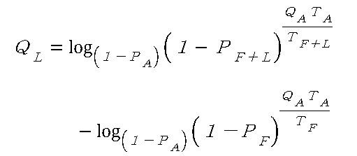
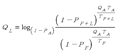


여기서, 화염 센서(1)에 대해서 QA, TA에 출하시에 기준값으로서 정한 값을 측정해 두고 기억부(162)에 저장하고 있던 것을 이용하고, 기준 광원의 QL을 동일하게 저장하고 있던 것으로부터 취득하여, 또한 펄스 폭(T) 및 방전 확률(PF와 PF +L)은 실측한 것을 이용해서, 화염 센서(1)의 현재의 감도로서의 지수인 방전 확률(PA)을 상기 수식 16으로부터 구한다. 또한, 구한 PA를 수식 10에 역산 투입하면, 미지수인 화염(300)의 현재의 수광량(QF)도 얻어진다. 그에 의해, 감도 보정용의 측정시(기준 광원 점등시)에도, 측정 대상의 화염(300)의 광의 세기가 구해진다.Here, the value set as a reference value at the time of shipment to Q A and T A is measured for the
본원 발명의 실시양태인 진단 단계를 도 4의 흐름에 기초하여 설명한다(도면 중 단계를 Snn이라고 부름).The diagnostic step, which is an embodiment of the present invention, will be described based on the flow of FIG. 4 (the steps in the figure are referred to as Snn).
본 조정 흐름은 2개의 모드에서 화염 센서의 파라미터를 계측한다.This adjustment flow measures the parameters of the flame sensor in two modes.
·진단 처리를 스타트한다(S10).- Start the diagnostic process (S10).
·모드 0: 기준 광원을 소등한 상태로 방전 확률(PL)을 측정한다(S11).Mode 0: The discharge probability P L is measured with the reference light source turned off (S11).
·모드 1: 기준 광원을 점등한 상태로 방전 확률(PF +L)을 측정한다(S12).Mode 1: The discharge probability (P F + L ) is measured while the reference light source is lit (S12).
상기 2개의 모드는 각각, 소정의 샘플을 얻기 위해 복수회(도 3에 나타냄) 기본적 루틴을 실행함으로써 구성된다.The two modes are each configured by executing a basic routine (shown in FIG. 3) a plurality of times to obtain a predetermined sample.
·수식 10으로부터 수식 16을 연산하여 현재의 방전 확률(PA) 및 수식 10으로부터 역산하여 수광량(QF)을 산출한다(S13).(16) from equation (10) and calculates the light reception amount (Q F ) by back calculation from the current discharge probability (P A ) and equation (10) (S13).
·방전 확률(PA)을 미리 정한 임계값과 비교하여, 화염 센서(1)의 열화를 검출한다(S14).The deterioration of the
또한, 모드의 전환은 연산 장치(3)의 중앙 처리부(163)로부터의 지령으로 이루어지며, 기준 광원(200)을 온/오프 제어하는 것이다.The switching of the mode is performed by a command from the
그 외, 여러 가지의 변형 실시는 가능하다. 그와 같은, 설계 사항적인 변형을 행하였다고 해도, 본원 발명의 범위에 속하는 것이다.In addition, various modifications are possible. Even if such design modifications are made, they are within the scope of the present invention.
1: 화염 센서
2: 외부 전원
3: 연산 장치
11: 전원 회로
12: 인가 전압 생성 회로
13: 트리거 회로
14: 분압 저항
15: 전압 검출 회로
16: 샘플링 회로
161: A/D 변환부
162: 기억부
163: 중앙 처리부
164: 판정부
200: 기준 광원
300: 버너 화염1: Flame sensor 2: External power source
3: computing device 11: power supply circuit
12: Applied voltage generating circuit 13: Trigger circuit
14: voltage dividing resistor 15: voltage detecting circuit
16: sampling circuit 161: A / D conversion section
162: storage unit 163: central processing unit
164: Judgment section 200: Reference light source
300: Burner flame
Claims (3)
상기 연산 장치는,
상기 화염 센서를 구동시키는 펄스를 생성하는 인가 전압 생성부와,
상기 화염 센서에 흐르는 전기 신호를 계측하는 전압 검출부와,
상기 화염 센서가 갖는 감도 파라미터를 미리 기억하는 기억부와,
상기 감도 파라미터 중 기지(旣知)의 수광량, 펄스 폭 및 방전 확률의 파라미터, 및 실제의 펄스 폭과 계측한 방전 횟수로부터 얻어지는 방전 확률을 이용하여, 그 화염의 수광량을 구하는 중앙 처리부
를 구비하고,
상기 중앙 처리부는,
기준 광원을 소등하였을 때에 상기 화염 센서에서의 방전 확률을 계측하는 제1 모드와,
기준 광원을 점등하였을 때에 상기 화염 센서에서의 방전 확률을 계측하는 제2 모드
를 실행하여, 이 제1 모드와 제2 모드에서 얻은 데이터로부터 현재의 화염 센서의 방전 확률을 산출하는 것을 특징으로 하는 화염 검출 시스템.A flame detection system comprising a flame sensor for detecting light, an arithmetic unit and a reference light source,
The computing device includes:
An applied voltage generator for generating a pulse for driving the flame sensor;
A voltage detector for measuring an electrical signal flowing through the flame sensor;
A storage unit for storing in advance the sensitivity parameter of the flame sensor;
A central processing unit for obtaining a received light amount of the flame by using the parameters of the received light amount, the pulse width and the discharge probability of the sensitivity parameter, and the discharge probability obtained from the actual pulse width and the measured number of discharges,
And,
The central processing unit,
A first mode for measuring a discharge probability in the flame sensor when the reference light source is turned off,
And a second mode for measuring a discharge probability in the flame sensor when the reference light source is turned on
And calculates the discharge probability of the current flame sensor from the data obtained in the first mode and the second mode.
상기 중앙 처리부는 상기 현재의 화염 센서의 방전 확률로부터 그 화염의 수광량을 구하는 것을 특징으로 하는 화염 검출 시스템.The method according to claim 1,
Wherein the central processing unit obtains a received light amount of the flame from a discharge probability of the current flame sensor.
상기 현재의 방전 확률을 미리 정해진 임계값과 비교하여 화염 센서의 열화 진단을 행하는 것을 특징으로 하는 화염 검출 시스템.3. The method according to claim 1 or 2,
Wherein the deterioration diagnosis of the flame sensor is performed by comparing the current discharge probability with a predetermined threshold value.
Applications Claiming Priority (2)
| Application Number | Priority Date | Filing Date | Title |
|---|---|---|---|
| JP2015106035A JP6508773B2 (en) | 2015-05-26 | 2015-05-26 | Flame detection system |
| JPJP-P-2015-106035 | 2015-05-26 |
Publications (2)
| Publication Number | Publication Date |
|---|---|
| KR20160138902A true KR20160138902A (en) | 2016-12-06 |
| KR101879491B1 KR101879491B1 (en) | 2018-07-17 |
Family
ID=57398326
Family Applications (1)
| Application Number | Title | Priority Date | Filing Date |
|---|---|---|---|
| KR1020160061902A KR101879491B1 (en) | 2015-05-26 | 2016-05-20 | Flame detection system |
Country Status (4)
| Country | Link |
|---|---|
| US (1) | US9746181B2 (en) |
| JP (1) | JP6508773B2 (en) |
| KR (1) | KR101879491B1 (en) |
| CN (1) | CN106197671B (en) |
Cited By (1)
| Publication number | Priority date | Publication date | Assignee | Title |
|---|---|---|---|---|
| KR20180133327A (en) * | 2017-06-06 | 2018-12-14 | 아즈빌주식회사 | Flame detecting system |
Families Citing this family (16)
| Publication number | Priority date | Publication date | Assignee | Title |
|---|---|---|---|---|
| US10690540B2 (en) | 2015-10-06 | 2020-06-23 | View, Inc. | Multi-sensor having a light diffusing element around a periphery of a ring of photosensors |
| US10533892B2 (en) | 2015-10-06 | 2020-01-14 | View, Inc. | Multi-sensor device and system with a light diffusing element around a periphery of a ring of photosensors and an infrared sensor |
| US11674843B2 (en) | 2015-10-06 | 2023-06-13 | View, Inc. | Infrared cloud detector systems and methods |
| US11781903B2 (en) | 2014-09-29 | 2023-10-10 | View, Inc. | Methods and systems for controlling tintable windows with cloud detection |
| EP3875996A1 (en) * | 2014-09-29 | 2021-09-08 | View, Inc. | Sunlight intensity or cloud detection with variable distance sensing |
| TWI727931B (en) | 2014-09-29 | 2021-05-21 | 美商唯景公司 | Combi-sensor systems |
| US11566938B2 (en) | 2014-09-29 | 2023-01-31 | View, Inc. | Methods and systems for controlling tintable windows with cloud detection |
| US11255722B2 (en) | 2015-10-06 | 2022-02-22 | View, Inc. | Infrared cloud detector systems and methods |
| KR200486223Y1 (en) * | 2017-08-28 | 2018-04-18 | 한국발전기술주식회사 | Mobile terminal device having light source and simulation device for igniter using the same |
| JP2020153754A (en) * | 2019-03-19 | 2020-09-24 | アズビル株式会社 | Fire detection system and received light quantity measuring method |
| JP2020165830A (en) * | 2019-03-29 | 2020-10-08 | アズビル株式会社 | Flame detection system and flame level detection method |
| JP2021131253A (en) * | 2020-02-18 | 2021-09-09 | アズビル株式会社 | Light detection system, discharge probability calculating method, and received light quantity measuring method |
| JP2021131254A (en) * | 2020-02-18 | 2021-09-09 | アズビル株式会社 | Light detection system, discharge probability calculating method, and received light quantity measuring method |
| JP2021131249A (en) * | 2020-02-18 | 2021-09-09 | アズビル株式会社 | Light detection system and discharge probability calculating method |
| JP2021131248A (en) * | 2020-02-18 | 2021-09-09 | アズビル株式会社 | Light detection system, discharge probability calculating method, and received light quantity measuring method |
| GB2595499A (en) | 2020-05-28 | 2021-12-01 | Bosch Thermotechnology Ltd Uk | Method for operating a failure protection device of a flame sensor |
Citations (5)
| Publication number | Priority date | Publication date | Assignee | Title |
|---|---|---|---|---|
| JPH05157627A (en) * | 1991-12-05 | 1993-06-25 | Nikko Kyodo Co Ltd | Photometric device |
| JPH0714831Y2 (en) * | 1990-06-14 | 1995-04-10 | 山武ハネウエル株式会社 | Ultraviolet sensor diagnostic device |
| JPH07318487A (en) | 1994-05-24 | 1995-12-08 | Dairetsuku Kk | Ozone concentration meter |
| JP2011141290A (en) | 2011-03-25 | 2011-07-21 | Yamatake Corp | Flame detection device |
| JP2013171560A (en) * | 2012-02-23 | 2013-09-02 | Hochiki Corp | Flame monitoring device |
Family Cites Families (28)
| Publication number | Priority date | Publication date | Assignee | Title |
|---|---|---|---|---|
| US4415806A (en) * | 1978-04-25 | 1983-11-15 | Cerberus Ag | Radiation detector for a flame alarm |
| DE2823410A1 (en) * | 1978-04-25 | 1979-11-08 | Cerberus Ag | FLAME DETECTOR |
| US4575333A (en) * | 1984-05-02 | 1986-03-11 | Bryant Jack A | Flame monitor time delay control |
| US4665390A (en) * | 1985-08-22 | 1987-05-12 | Hughes Aircraft Company | Fire sensor statistical discriminator |
| US4742236A (en) * | 1985-04-27 | 1988-05-03 | Minolta Camera Kabushiki Kaisha | Flame detector for detecting phase difference in two different wavelengths of light |
| US4736105A (en) * | 1986-04-09 | 1988-04-05 | Tri-Star Research, Inc. | Flame detector system |
| US5237512A (en) * | 1988-12-02 | 1993-08-17 | Detector Electronics Corporation | Signal recognition and classification for identifying a fire |
| IL95617A0 (en) * | 1990-09-09 | 1991-06-30 | Aviv Amirav | Pulsed flame detector method and apparatus |
| JP2623381B2 (en) * | 1991-06-15 | 1997-06-25 | ニッタン株式会社 | Flame sensing device |
| US5365223A (en) * | 1991-10-28 | 1994-11-15 | Honeywell Inc. | Fail-safe condition sensing circuit |
| US5333487A (en) * | 1991-11-15 | 1994-08-02 | Hughes Aircraft Company | Spark-excited fluorescence sensor |
| JPH06325269A (en) * | 1993-05-18 | 1994-11-25 | Matsushita Electric Works Ltd | Ultraviolet ray type sensor |
| JPH06325273A (en) * | 1993-05-18 | 1994-11-25 | Matsushita Electric Works Ltd | Ultraviolet ray type sensor |
| IL115287A (en) * | 1995-09-13 | 2000-02-17 | Aviv Amirav | Flame-based method and apparatus for analyzing a sample |
| US5850182A (en) * | 1997-01-07 | 1998-12-15 | Detector Electronics Corporation | Dual wavelength fire detection method and apparatus |
| JP2003232677A (en) * | 2002-02-08 | 2003-08-22 | Fuji Xerox Co Ltd | Uv radiometer and its calibration method |
| JP3909490B2 (en) * | 2002-06-28 | 2007-04-25 | 株式会社山武 | Flame detection device |
| WO2005111556A2 (en) * | 2004-05-07 | 2005-11-24 | Walter Kidde Portable Equipment, Inc. | Flame detector with uv sensor |
| US7297970B2 (en) * | 2005-03-29 | 2007-11-20 | Nohmi Bosai Ltd. | Flame detector |
| US8310801B2 (en) * | 2005-05-12 | 2012-11-13 | Honeywell International, Inc. | Flame sensing voltage dependent on application |
| JP2011043455A (en) * | 2009-08-24 | 2011-03-03 | Panasonic Electric Works Co Ltd | Illuminance sensor and illuminance sensor output value adjustment system |
| CN202195883U (en) * | 2011-06-17 | 2012-04-18 | 四川天微电子有限责任公司 | High-speed ultraviolet flame detector |
| CN102496236B (en) * | 2011-12-27 | 2013-10-02 | 公安部沈阳消防研究所 | Direct-injection type flame detector with self-checking light source and flame detection method |
| JP5922452B2 (en) * | 2012-03-19 | 2016-05-24 | ホーチキ株式会社 | Flame monitoring device |
| JP5832948B2 (en) * | 2012-03-30 | 2015-12-16 | アズビル株式会社 | Flame detection device |
| CN202792092U (en) * | 2012-08-14 | 2013-03-13 | 徐州燃控科技股份有限公司 | Spectral analysis type visible light flame detector |
| US9528879B2 (en) * | 2013-01-21 | 2016-12-27 | Panasonic Intellectual Property Management Co., Ltd. | Infrared detection element, infrared detector, and infrared type gas sensor |
| US9784449B2 (en) * | 2014-05-30 | 2017-10-10 | Jed Margolin | Flame sensing system |
-
2015
- 2015-05-26 JP JP2015106035A patent/JP6508773B2/en not_active Expired - Fee Related
-
2016
- 2016-05-20 KR KR1020160061902A patent/KR101879491B1/en active IP Right Grant
- 2016-05-24 CN CN201610352755.7A patent/CN106197671B/en active Active
- 2016-05-25 US US15/164,340 patent/US9746181B2/en active Active
Patent Citations (5)
| Publication number | Priority date | Publication date | Assignee | Title |
|---|---|---|---|---|
| JPH0714831Y2 (en) * | 1990-06-14 | 1995-04-10 | 山武ハネウエル株式会社 | Ultraviolet sensor diagnostic device |
| JPH05157627A (en) * | 1991-12-05 | 1993-06-25 | Nikko Kyodo Co Ltd | Photometric device |
| JPH07318487A (en) | 1994-05-24 | 1995-12-08 | Dairetsuku Kk | Ozone concentration meter |
| JP2011141290A (en) | 2011-03-25 | 2011-07-21 | Yamatake Corp | Flame detection device |
| JP2013171560A (en) * | 2012-02-23 | 2013-09-02 | Hochiki Corp | Flame monitoring device |
Cited By (1)
| Publication number | Priority date | Publication date | Assignee | Title |
|---|---|---|---|---|
| KR20180133327A (en) * | 2017-06-06 | 2018-12-14 | 아즈빌주식회사 | Flame detecting system |
Also Published As
| Publication number | Publication date |
|---|---|
| CN106197671B (en) | 2019-12-13 |
| JP2016218003A (en) | 2016-12-22 |
| KR101879491B1 (en) | 2018-07-17 |
| US9746181B2 (en) | 2017-08-29 |
| JP6508773B2 (en) | 2019-05-08 |
| CN106197671A (en) | 2016-12-07 |
| US20160348907A1 (en) | 2016-12-01 |
Similar Documents
| Publication | Publication Date | Title |
|---|---|---|
| KR101879491B1 (en) | Flame detection system | |
| KR101860632B1 (en) | Flame detection system | |
| EP3279624B1 (en) | Light quantity detection device, and immunoanalysis device and charged particle beam device using same | |
| JP6782612B2 (en) | Flame detection system | |
| CN108088559B (en) | Flame detection system | |
| US10415829B2 (en) | Flame detecting system | |
| KR101879492B1 (en) | Flame detection system | |
| JP5832948B2 (en) | Flame detection device | |
| US11280672B2 (en) | Flame detection system, discharge probability calculating method, and received light quantity measuring method | |
| US20200300706A1 (en) | Flame detection system and received light quantity measuring method | |
| KR102574675B1 (en) | Light detection system, discharge probability calculation method and light receiving amount measurement method | |
| US20210262855A1 (en) | Light detection system, discharge probability calculating method, and received light quantity measuring method |
Legal Events
| Date | Code | Title | Description |
|---|---|---|---|
| A201 | Request for examination | ||
| E902 | Notification of reason for refusal | ||
| AMND | Amendment | ||
| E601 | Decision to refuse application | ||
| AMND | Amendment | ||
| X701 | Decision to grant (after re-examination) | ||
| GRNT | Written decision to grant |