KR20160138485A - Method and lift jet floatation system for shaping thin glass - Google Patents
Method and lift jet floatation system for shaping thin glass Download PDFInfo
- Publication number
- KR20160138485A KR20160138485A KR1020167029629A KR20167029629A KR20160138485A KR 20160138485 A KR20160138485 A KR 20160138485A KR 1020167029629 A KR1020167029629 A KR 1020167029629A KR 20167029629 A KR20167029629 A KR 20167029629A KR 20160138485 A KR20160138485 A KR 20160138485A
- Authority
- KR
- South Korea
- Prior art keywords
- glass structure
- array
- glass
- nozzle
- orifices
- Prior art date
Links
- 239000011521 glass Substances 0.000 title claims abstract description 91
- 238000000034 method Methods 0.000 title claims abstract description 37
- 238000007493 shaping process Methods 0.000 title claims description 7
- 238000010438 heat treatment Methods 0.000 claims abstract description 6
- 238000010304 firing Methods 0.000 claims description 8
- 239000007921 spray Substances 0.000 claims description 8
- 238000002347 injection Methods 0.000 claims description 6
- 239000007924 injection Substances 0.000 claims description 6
- 238000000465 moulding Methods 0.000 claims description 5
- 238000009826 distribution Methods 0.000 claims description 4
- 239000005340 laminated glass Substances 0.000 claims description 3
- 229920000642 polymer Polymers 0.000 claims description 3
- 230000000630 rising effect Effects 0.000 claims description 3
- 230000001174 ascending effect Effects 0.000 abstract description 6
- 239000007789 gas Substances 0.000 description 16
- 238000003491 array Methods 0.000 description 4
- 238000009434 installation Methods 0.000 description 4
- 238000005452 bending Methods 0.000 description 3
- 230000007246 mechanism Effects 0.000 description 3
- 238000012986 modification Methods 0.000 description 3
- 230000004048 modification Effects 0.000 description 3
- 238000005496 tempering Methods 0.000 description 3
- 238000005188 flotation Methods 0.000 description 2
- 239000000446 fuel Substances 0.000 description 2
- 238000004519 manufacturing process Methods 0.000 description 2
- 239000010409 thin film Substances 0.000 description 2
- 230000002411 adverse Effects 0.000 description 1
- 230000001143 conditioned effect Effects 0.000 description 1
- 238000007796 conventional method Methods 0.000 description 1
- 238000013461 design Methods 0.000 description 1
- 238000010586 diagram Methods 0.000 description 1
- 230000000694 effects Effects 0.000 description 1
- 239000005357 flat glass Substances 0.000 description 1
- 230000014509 gene expression Effects 0.000 description 1
- 230000005484 gravity Effects 0.000 description 1
- 239000011261 inert gas Substances 0.000 description 1
- 239000000203 mixture Substances 0.000 description 1
- 230000003287 optical effect Effects 0.000 description 1
- 238000012545 processing Methods 0.000 description 1
- 239000005361 soda-lime glass Substances 0.000 description 1
Images


Classifications
-
- C—CHEMISTRY; METALLURGY
- C03—GLASS; MINERAL OR SLAG WOOL
- C03B—MANUFACTURE, SHAPING, OR SUPPLEMENTARY PROCESSES
- C03B23/00—Re-forming shaped glass
- C03B23/02—Re-forming glass sheets
- C03B23/023—Re-forming glass sheets by bending
- C03B23/03—Re-forming glass sheets by bending by press-bending between shaping moulds
-
- C—CHEMISTRY; METALLURGY
- C03—GLASS; MINERAL OR SLAG WOOL
- C03B—MANUFACTURE, SHAPING, OR SUPPLEMENTARY PROCESSES
- C03B23/00—Re-forming shaped glass
- C03B23/02—Re-forming glass sheets
- C03B23/023—Re-forming glass sheets by bending
- C03B23/035—Re-forming glass sheets by bending using a gas cushion or by changing gas pressure, e.g. by applying vacuum or blowing for supporting the glass while bending
- C03B23/0352—Re-forming glass sheets by bending using a gas cushion or by changing gas pressure, e.g. by applying vacuum or blowing for supporting the glass while bending by suction or blowing out for providing the deformation force to bend the glass sheet
- C03B23/0357—Re-forming glass sheets by bending using a gas cushion or by changing gas pressure, e.g. by applying vacuum or blowing for supporting the glass while bending by suction or blowing out for providing the deformation force to bend the glass sheet by suction without blowing, e.g. with vacuum or by venturi effect
-
- C—CHEMISTRY; METALLURGY
- C03—GLASS; MINERAL OR SLAG WOOL
- C03B—MANUFACTURE, SHAPING, OR SUPPLEMENTARY PROCESSES
- C03B35/00—Transporting of glass products during their manufacture, e.g. hot glass lenses, prisms
- C03B35/14—Transporting hot glass sheets or ribbons, e.g. by heat-resistant conveyor belts or bands
- C03B35/16—Transporting hot glass sheets or ribbons, e.g. by heat-resistant conveyor belts or bands by roller conveyors
- C03B35/18—Construction of the conveyor rollers ; Materials, coatings or coverings thereof
-
- C—CHEMISTRY; METALLURGY
- C03—GLASS; MINERAL OR SLAG WOOL
- C03B—MANUFACTURE, SHAPING, OR SUPPLEMENTARY PROCESSES
- C03B35/00—Transporting of glass products during their manufacture, e.g. hot glass lenses, prisms
- C03B35/14—Transporting hot glass sheets or ribbons, e.g. by heat-resistant conveyor belts or bands
- C03B35/22—Transporting hot glass sheets or ribbons, e.g. by heat-resistant conveyor belts or bands on a fluid support bed, e.g. on molten metal
- C03B35/24—Transporting hot glass sheets or ribbons, e.g. by heat-resistant conveyor belts or bands on a fluid support bed, e.g. on molten metal on a gas support bed
-
- Y—GENERAL TAGGING OF NEW TECHNOLOGICAL DEVELOPMENTS; GENERAL TAGGING OF CROSS-SECTIONAL TECHNOLOGIES SPANNING OVER SEVERAL SECTIONS OF THE IPC; TECHNICAL SUBJECTS COVERED BY FORMER USPC CROSS-REFERENCE ART COLLECTIONS [XRACs] AND DIGESTS
- Y02—TECHNOLOGIES OR APPLICATIONS FOR MITIGATION OR ADAPTATION AGAINST CLIMATE CHANGE
- Y02P—CLIMATE CHANGE MITIGATION TECHNOLOGIES IN THE PRODUCTION OR PROCESSING OF GOODS
- Y02P40/00—Technologies relating to the processing of minerals
- Y02P40/50—Glass production, e.g. reusing waste heat during processing or shaping
- Y02P40/57—Improving the yield, e-g- reduction of reject rates
Abstract
본원에는 유리 구조를 성형하기 위한 시스템이 개시되며, 상기 시스템은 평면을 따라 유리 구조를 이송하기 위한 다수의 롤러를 포함하는 롤 컨베이어; 다수의 오리피스를 갖춘 팁을 포함하는 하나 또는 그 이상의 다수의 노즐을 구비한 상승 분사 어레이; 및 상기 롤 컨베이어 상에 위치된 성형 몰드를 포함하며, 상기 상승 분사 어레이는 각각의 노즐 팁이 다수의 롤러의 중심선 상에 위치되도록 롤 컨베이어 아래에 배치된다. 또한 본원에는 유리 구조를 성형하기 위한 방법이 개시되며, 상기 방법은 유리 구조를 가열하는 단계 및 상승 분사 어레이와 성형 몰드간 위치에 롤 컨베이어 상에 유리 구조를 이송하는 단계를 포함하며, 가스는 롤 컨베이어로부터 유리 구조를 상승시키기에 충분한 힘에 의해 상승 분사 어레이로부터 유동된다.Disclosed herein is a system for forming a glass structure, the system comprising: a roll conveyor including a plurality of rollers for conveying a glass structure along a plane; An elevated jet array having one or more nozzles including a tip with a plurality of orifices; And a forming mold positioned on the roll conveyor, wherein the raised jet array is disposed below the roll conveyor such that each nozzle tip is located on a centerline of the plurality of rollers. Also disclosed herein is a method for forming a glass structure comprising heating a glass structure and transferring the glass structure onto a roll conveyor at a location between the elevated jet array and the forming mold, From the ascending jet array by a force sufficient to lift the glass structure from the conveyor.
Description
본 출원은 35 U.S.C.§119 하에 2014년 3월 31일 출원된 미국 가출원 제61/972,784호를 우선권 주장하고 있으며, 상기 특허 문헌의 내용은 참조를 위해 본 발명에 모두 포함된다.This application claims priority to U.S. Provisional Application No. 61 / 972,784, filed March 31, 2014, under 35 U.S.C. §119, which is incorporated herein by reference in its entirety for all purposes.
본 개시는 통상 유리 구조를 성형하기 위한 방법 및 시스템에 관한 것으로, 특히 박막 유리를 구부리기 위한 상승 분사형 부상 시스템에 관한 것이다.This disclosure relates generally to methods and systems for forming glass structures, and more particularly to elevated-jet float systems for bending thin glass.
박막 유리 구조를 열적으로 성형 및 형성하기 위한 능력은 자동차 산업과 같은 다양한 산업과 점점 더 관련이 깊어지고 있다. 자동차용 창 유리의 생산은 점점 증가하는 절박한 환경 및 안전의 요구로 인해 끊임없이 변화하는 복잡한 공정이다. 높은 광학 품질 및 낮은 중량을 갖는 복잡한 유리 형태의 요구는 정부의 규정이 연비 증가 및 배출가스 감소를 요구함에 따라 점점 커지고 있다. 보다 얇은 유리로부터 자동차 부품을 만들기 위한 능력은 낮은 차량 무게, 향상된 연비, 감소된 배출가스, 및/또는 향상된 차량 무게 분배(예컨대, 낮은 무게 중심)로 옮겨지고 있다.The ability to thermally shape and form thin film glass structures is becoming increasingly relevant to a variety of industries, such as the automotive industry. The production of automotive window glass is a complex process that is constantly changing due to the ever-increasing demands of the environment and safety. The demand for complex glass forms with high optical quality and low weight is increasing as government regulations require increased fuel economy and reduced emissions. The ability to make automotive parts from thinner glass is being transferred with lower vehicle weight, improved fuel economy, reduced emissions, and / or improved vehicle weight distribution (e.g., lower center of gravity).
유리를 성형하기 위한 종래의 방법들은 롤 컨베이어(roll conveyor) 상에 유리 구조를 배치하는 단계, 시트를 가열하여 연화(soft)시키기 위해 노를 통해 유리를 이송하는 단계, 및 성형 몰드의 아래에 연화된 유리를 위치시키는 단계를 포함하며, 상기 연화된 유리는 성형 몰드와 접촉하도록 상승 분사 어레이에 의해 위쪽으로 상승된다. 상기 성형 몰드는 유리 구조가 원하는 형태로 형성될 수 있는 표면으로서 제공된다. 그러한 상승 분사 어레이 패턴은 통상 각기 다른 형태 및/또는 요소에 따라 다르며, 조절불가 고정 직경/오리피스(orifice) 노즐 및/또는 조절가능 나사형 노즐을 포함한다. 그러한 노즐들은 롤러들 아래에 위치되고, 조절되어 모아진 가열된 공기 스트림을 롤러들 사이로 위로 날려 보낸다.Conventional methods for forming glass include placing a glass structure on a roll conveyor, transporting the glass through a furnace to heat and soften the sheet, and softening Wherein the softened glass is lifted upwards by the raised jet array to contact the forming mold. The forming mold is provided as a surface on which the glass structure can be formed in the desired shape. Such raised spray array patterns typically vary with different shapes and / or elements and include non-adjustable fixed diameter / orifice nozzles and / or adjustable threaded nozzles. Such nozzles are located below the rollers and blow the heated air stream that has been conditioned and collected between the rollers.
기존의 상승 분사 시스템은 약 3 mm 내지 약 6 mm 범위의 두께를 갖는 소다-석회(soda-lime) 유리와 같은 두꺼운 통상의 유리에 가장 적합하다. 두꺼운 유리 구조는 보통 국소적 변형을 신경쓰지 않고 그러한 노즐들로부터의 압력에 견딜 수 있다. 그러나, 보다 얇은 유리(예컨대, 약 3.0 mm보다 작은 두께, 약 0.3 mm와 약 2.0 mm 사이의 두께, 약 0.5 mm와 약 1.5 mm 사이의 두께, 및 그 모든 범위 및 그 사이의 하위 범위의 두께)가 이들 통상의 상승 분사 시스템을 이용하여 처리될 경우, 그러한 유리는 노즐들로부터의 국소적 상향력으로 인해 각 노즐 사이에서 비틀어지고 구부러지는 경향이 있다.Conventional rising injection systems are best suited for thick conventional glasses such as soda-lime glass having a thickness ranging from about 3 mm to about 6 mm. The thick glass structure is usually able to withstand the pressure from such nozzles without worrying about local deformation. However, thinner glass (e.g., less than about 3.0 mm thick, between about 0.3 mm and about 2.0 mm thick, between about 0.5 mm and about 1.5 mm thick, and all ranges and subranges therebetween) Such glass is tended to twist and bend between each nozzle due to the local upward force from the nozzles when they are processed using these conventional rising injection systems.
따라서, 보다 얇은 유리 구조를 성형 및 템퍼링(tempering)하기 위한 방법 및 시스템을, 좀더 구체적으로 유리 비틀어짐을 감소 및/도는 없애기 위해 보다 큰 표면 영역에 걸쳐 상향의 상승력을 보다 균일하게 분배하는 상승 분사 어레이를 제공하는 것이 효과적일 것이다. 제조 비용 및/또는 처리 시간을 감소시키기 위해, 추가로 통상의 유리(예컨대, 두꺼운)를 구부리고 템퍼링하기 위한 기존의 시스템과 연계되어 적어도 부분적으로 기능할 수 있는 시스템을 제공하는 것이 효과적일 것이다.Accordingly, it is an object of the present invention to provide a method and system for shaping and tempering thinner glass structures, and more particularly to a method and system for shaping and tempering thinner glass structures, It will be effective. In order to reduce manufacturing costs and / or processing time, it would be effective to provide a system that can at least partially function in conjunction with existing systems for bending and tempering conventional glass (e.g., thick).
본 개시는 다양한 실시예들에 있어서 하나 또는 그 이상의 유리 구조를 성형하기 위한 상승 분사형 부상 시스템에 관한 것으로, 상기 상승 분사형 부상 시스템은 평면을 따라 유리 구조(들)를 이송하고, 상기 평면에 거의 평행한 중심선을 갖는 다수의 롤러를 포함하는 롤 컨베이어; 다수의 오리피스를 갖춘 팁을 포함하는 하나 또는 그 이상의 다수의 노즐을 구비한 상승 분사 어레이; 및 성형 몰드를 포함하며, 상기 롤 컨베이어는 거의 상기 상승 분사 어레이와 상기 성형 몰드 사이에 위치되고, 상기 상승 분사 어레이는 각각의 노즐 팁이 다수의 롤러의 중심선 상에 위치되도록 배치된다.The present disclosure is directed to an elevated-jet float system for forming one or more glass structures in various embodiments, wherein the elevated jet float system conveys the glass structure (s) along a plane and is substantially parallel to the plane A roll conveyor including a plurality of rollers having a centerline; An elevated jet array having one or more nozzles including a tip with a plurality of orifices; Wherein the roll conveyor is positioned substantially between the elevated jet array and the forming mold and the raised jet array is positioned such that each nozzle tip is located on a centerline of the plurality of rollers.
또한, 본 개시는 하나 또는 그 이상의 유리 구조를 성형하기 위한 방법에 관한 것으로, 상기 유리 구조 성형 방법은 평면에 거의 평행한 중심선을 갖는 다수의 롤러를 포함하는 롤 컨베이어 상의 상기 평면을 따라 유리 구조(들)를 이송하는 단계; 상기 유리 구조를 가열하는 단계; 및 성형 몰드와 상승 분사 어레이간 롤 컨베이어 상에 상기 유리 구조를 위치시키는 단계를 포함하며, 상기 상승 분사 어레이는 다수의 오리피스를 갖춘 팁을 포함하는 하나 또는 그 이상의 다수의 노즐을 구비하고, 상기 상승 분사 어레이는 각각의 노즐 팁이 다수의 롤러의 중심선 상에 위치되도록 배치되며, 상기 가스 스트림은 상기 롤 컨베이어로부터 상기 유리 구조를 상승시키기에 충분한 조합된 힘에 의해 상기 상승 분사 어레이의 각 오리피스로부터 유동된다.The present disclosure also relates to a method for forming one or more glass structures, wherein the glass structure forming method comprises forming a glass structure along the plane on a roll conveyor comprising a plurality of rollers having a centerline substantially parallel to the plane Lt; / RTI > Heating the glass structure; And positioning the glass structure on a roll conveyor between a forming mold and a raising spray array, the raising spray array having one or more nozzles including a tip with a plurality of orifices, The firing array is arranged such that each nozzle tip is located on the centerline of the plurality of rollers and the gas stream is flowed from each orifice of the raised firing array by a combined force sufficient to lift the glass structure from the roll conveyor do.
더욱이, 본 개시는 하나 또는 그 이상의 유리 구조를 상승 또는 성형하기 위한 시스템에 관한 것으로, 상기 시스템은 평면을 따라 유리 구조(들)를 이송하고, 상기 평면에 거의 평행한 중심선을 갖는 다수의 롤러를 포함하는 롤 컨베이어; 및 다수의 오리피스를 갖춘 팁을 포함하는 하나 또는 그 이상의 다수의 노즐을 구비한 각각의 상승 노즐 어레이를 포함하며, 각각의 노즐 팁은 상기 다수의 롤러의 중심선 상에 위치된다.Moreover, the present disclosure relates to a system for raising or shaping one or more glass structures, the system comprising a plurality of rollers having a centerline substantially parallel to the plane, A roll conveyor including; And a respective riser nozzle array having one or more nozzles including a tip with a plurality of orifices, each nozzle tip being located on a centerline of the plurality of rollers.
본 개시의 추가 특징 및 장점들은 이하의 상세한 설명에 기술되며, 그 일부는 통상의 기술자가 그러한 설명으로부터 용이하게 알 수 있거나 또는 이하의 상세한 설명, 청구항 뿐만 아니라 수반된 도면을 포함하는 본원에 기술된 방법들을 실시함으로써 인식할 수 있을 것이다.Additional features and advantages of the present disclosure will be set forth in the description which follows, and in part will be readily apparent to those skilled in the art from the foregoing description, or may be learned by those skilled in the art from the following detailed description, Methods can be realized.
상기한 일반적인 설명 및 이하의 상세한 설명은 본 개시의 다양한 실시예들을 제공하며, 청구항의 성질 및 특성을 이해하기 위한 개요 또는 기초를 제공하기 위한 것이라는 것을 알아야 한다. 수반의 도면들은 본 개시를 좀더 잘 이해할 수 있게 하기 위해 제공되며, 본 명세서에 통합되어 그 일부를 구성한다. 그러한 도면들은 본 개시의 다양한 실시예들을 기술하며, 상세한 설명과 함께 본 개시의 원리 및 동작들을 설명하기 위해 제공된다.It is to be understood that both the foregoing general description and the following detailed description present various embodiments of the disclosure and are intended to provide an overview or basis for understanding the nature and character of the claims. The accompanying drawings are provided to facilitate a better understanding of the disclosure, and are incorporated in and constitute a part of this disclosure. Such drawings describe various embodiments of the present disclosure and are provided to explain the principles and operations of the present disclosure in conjunction with the detailed description.
이하의 상세한 설명은 다음의 도면들을 참조함으로써 좀더 잘 이해될 수 있고, 유사한 구조에는 유사한 도면참조부호를 표시한다:
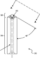
도 1은 본 개시의 일 실시예에 따른 상승 분사형 부상 시스템을 나타내는 측면도이고;
도 2는 본 개시의 일 실시예에 따라 최초 설치 및 위치된 노즐을 나타내는 도식적 도면이고;
도 3a는 본 개시의 일 실시예에 따른 다수의 오리피스를 갖는 노즐을 나타내는 측면도이고;
도 3b는 본 개시의 일 실시예에 따른 다수의 오리피스를 갖는 노즐을 나타내는 도 3a의 A-A 라인에 따른 상승도이며;
도 3c는 본 개시의 일 실시예에 따른 다수의 오리피스를 갖는 노즐을 나타내는 상면도이다.BRIEF DESCRIPTION OF THE DRAWINGS The following detailed description will be better understood by reference to the following drawings,
BRIEF DESCRIPTION OF THE DRAWINGS FIG. 1 is a side view of a lift-off type flotation system in accordance with one embodiment of the present disclosure; FIG.
Figure 2 is a schematic diagram illustrating a nozzle initially installed and positioned in accordance with one embodiment of the present disclosure;
Figure 3a is a side view of a nozzle having a plurality of orifices in accordance with one embodiment of the present disclosure;
Figure 3B is an elevation view according to line AA of Figure 3A showing a nozzle having a plurality of orifices in accordance with one embodiment of the present disclosure;
3C is a top view of a nozzle having a plurality of orifices in accordance with one embodiment of the present disclosure;
본원에는 하나 또는 그 이상의 유리 구조를 성형하기 위한 상승 분사형 부상 시스템이 개시되며, 상기 상승 분사형 부상 시스템은 평면을 따라 유리 구조(들)를 이송하고, 상기 평면에 거의 평행한 중심선을 갖는 다수의 롤러를 포함하는 롤 컨베이어; 다수의 오리피스를 갖춘 팁을 포함하는 하나 또는 그 이상의 다수의 노즐을 구비한 상승 분사 어레이; 및 성형 몰드를 포함하며, 상기 롤 컨베이어는 거의 상기 상승 분사 어레이와 상기 성형 몰드 사이에 위치되고, 상기 상승 분사 어레이는 사실상 각각의 노즐 팁이 다수의 롤러의 중심선 상에 위치되도록 롤 컨베이어 아래에 배치된다.Disclosed herein is a lift-up type float system for forming one or more glass structures, the lift-up float type system comprising a plurality of rollers having a centerline substantially parallel to the plane, A roll conveyor comprising: An elevated jet array having one or more nozzles including a tip with a plurality of orifices; And a shaping mold, the roll conveyor being positioned substantially between the elevated jet array and the forming mold, the elevated jet array being disposed under the roll conveyor such that virtually each nozzle tip is located on the centerline of the plurality of rollers do.
또한 본원에는 유리 구조를 상승 또는 성형하기 위한 시스템이 개시되며, 상기 시스템은 평면을 따라 유리 구조를 이송하고, 상기 평면에 거의 평행한 중심선을 갖는 다수의 롤러를 포함하는 롤 컨베이어; 및 다수의 오리피스를 갖춘 팁을 포함하는 하나 또는 그 이상의 다수의 노즐을 구비한 각각의 상승 노즐 어레이를 포함하며, 각각의 노즐 팁은 상기 다수의 롤러의 중심선 상에 위치된다.Also disclosed herein is a system for raising or shaping a glass structure, the system comprising: a roll conveyor for conveying a glass structure along a plane and comprising a plurality of rollers having a centerline substantially parallel to the plane; And a respective riser nozzle array having one or more nozzles including a tip with a plurality of orifices, each nozzle tip being located on a centerline of the plurality of rollers.
상승 분사 시스템Up injection system
도 1에 따르면, 하나 또는 그 이상의 유리 구조(G)가 지향 평면(120; 이하 간단히 '평면'이라 함)을 따라 이송되는 다수의 롤러(110)를 갖춘 롤 컨베이어(100)를 포함하는 상승 분사형 부상 시스템의 일 실시예가 나타나 있다. 예시의 유리 구조는 한정하진 않지만 몇가지 예를 들자면 하나의 유리 시트, 단일 스택의 다수의 유리 시트, 유리-유리 라미네이트(laminate) 구조, 및 유리-폴리머 라미네이트 구조를 포함한다. 그러한 유리 구조는 노(furnace) 또는 다른 가열 수단(나타내지 않음)을 거쳐 이송되거나, 또는 다른 적절한 수단이 성형 전에 그 유리 구조를 연화시키기 위해 사용될 것이다. 다양한 실시예들에 따르면, 상기 유리 구조는 시트가 성형 또는 몰딩될 수 있는 온도로 가열될 것이다.1, there is shown a top view of a
상기 다수의 롤러는 상기 평면(120)에 거의 평행한 중심선(130)을 갖는다. 상승 분사 어레이(140)는 롤 컨베이어 아래에 위치되고, 다수의 노즐(150)을 포함하며, 그러한 각각의 노즐은 다수의 오리피스를 갖춘 팁(160; tip)을 포함한다. 도 3a-c는 그러한 노즐 오리피스의 상세한 도면을 나타낸다. 상기 상승 분사 어레이는 각각의 노즐 팁(160)이 롤러(110)들 사이 및 상기 중심선(130) 상에 위치되도록 배치된다. 그러한 노즐(150)들의 위치는 특히 도 2에 더 잘 나타나 있다.The plurality of rollers have a
상기 유리 구조(G)는 이송되어 성형 몰드(180) 아래 및 상승 분사 어레이(140) 위에 위치될 것이다. 상기 노즐(150)들은 상기 유리 구조에 상향의 가스 유동을 공급한다. 한정하진 않지만 공기를 포함하는 소정의 가스로부터 선택되는 가압 가스가 적절한 소스(170)로부터 상기 상승 분사 어레이(140)에 제공된다. 상기 유리 구조(G)는 노즐(150)들로부터의 그러한 유동에 의해 롤 컨베이어(100)로부터 상승되어 상기 성형 몰드(180)의 하향의 대면(190)과 접촉이 이루어진다. 상기 성형 몰드(180)는 상기 롤 컨베이어로부터 받은 유리 구조를 지지하기 위해 선택적으로 진공이 제공되는 하나 또는 그 이상의 개구(나타내지 않음)를 포함할 것이다.The glass structure G will be transported and positioned below the forming
다양한 실시예들에 따르면, 상기 상승 분사 어레이(140)는 다수의 오리피스를 갖춘 팁(160)을 포함하는 하나 또는 그 이상의 노즐(150)을 구비한다. 다른 예에 있어서, 각각의 노즐(150)은 다수의 오리피스를 갖춘 팁(160)을 포함한다. 다른 실시예들에 따르면, 상기 노즐(150)들은 동일할 것이다. 또 다른 실시예들에 있어서, 상기 상승 분사 어레이의 하나 또는 그 이상의 다수의 노즐(150)은 인접한 노즐과 다른 오리피스의 분배를 갖는다.According to various embodiments, the raised
도 2는 본 개시의 일 형태에 따라 구성되고 본 개시의 일 실시예에 따라 위치된 분사 노즐(250a; 위치 "a") 및 본 개시의 일 실시예에 따라 구성된(그러나 최초 설치된 것으로 위치된) 노즐(250b; 위치 "b")을 나타내는 도식적 도면이다. 소정의 실시예들에 있어서, 설치 후, 그 개시 시점의 노즐 어레이는 노즐 팁들이 롤러 중심선(230) 상에 있도록 위치 "a"로 상승될 것이다. 기존의 시스템들은 예컨대 롤 컨베이어 아래의 위치로 레일들 상에서 슬라이딩함으로써 설치 및 제거될 수 있는 종래의 상승 분사 어레이들을 채용할 것이다. 본 개시의 다양한 형태들에 따르면, 본원에 개시된 상승 분사 어레이는 기존의 레일들을 이용하여 유사하게 설치 및 제거되고(위치 "b") 이후 본원에 개시된 바와 같이 노즐 팁들이 롤러들 사이에 그리고 롤러 중심선 위에 위치되도록 소정의 방법에 의해 상승될 수 있다(위치 "a"). 선택적으로, 전체 상승 분사 어레이를 상승시키는 대신, 노즐들 자체가 수직으로 조절될 수 있는데, 즉 그것들은 그 노즐 팁들이 중심선 상에 위치되도록 사용 동안 "팝 업(pop up)"으로 디자인될 수 있다.Figure 2 illustrates an
도 2에 나타낸 바와 같이, 롤러(210)들의 피치(v)는 각 롤러의 중심으로부터 측정된 바와 같은 그러한 롤러들간 거리를 나타낸다. 그러한 피치(v)는 상기 컨베이어에 따라 변경될 수 있다. 소정의 실시예들에 있어서, 상기 피치(v)는, 약 2인치 내지 약 8인치의 범위, 예컨대 그 모든 범위 및 그 사이의 하위 범위를 포함하여, 약 3인치 내지 약 6인치의 범위, 또는 약 4인치의 범위가 될 수 있다. 노즐(250)들은 노즐 팁(260)들이 중심선(230) 상에 그리고 롤러들의 상부로부터의 거리(w)에 위치하도록 다양한 실시예들에 따라 배치될 수 있다. 또한 그러한 거리는 변경될 수 있으며, 소정의 실시예들에서 약 0.5인치 내지 약 4인치의 범위, 예컨대 그 모든 범위 및 그 사이의 하위 범위를 포함하여, 약 1인치 내지 약 2인치의 범위가 될 수 있다. 설치 위치 "b"와 상승 위치 "a"간 거리(x)는 변경될 수 있으며, 다양한 실시예들에서 약 1인치 내지 약 4인치의 범위, 예컨대 그 모든 범위 및 그 사이의 하위 범위를 포함하여, 약 2인치 내지 약 3인치의 범위가 될 수 있다. 설치시에, 위치 "b"의 노즐들은 롤러들 아래, 예컨대 롤러들의 하부로부터의 거리(y)에 위치된다. 또한 이러한 거리(y)는 변경될 수 있으며, 소정의 실시예들에서 약 0.5인치 내지 약 2인치의 범위, 예컨대 그 모든 범위 및 그 사이의 하위 범위를 포함하여, 약 1인치 내지 약 1.5인치의 범위가 될 수 있다. 더욱이 상기 노즐(250)들은 소정의 치수, 예컨대 변경될 수 있으며, 약 1인치 내지 약 4인치의 범위, 즉 그 모든 범위 및 그 사이의 하위 범위를 포함하여, 약 2인치 내지 약 3.5인치, 또는 약 2.5인치 내지 약 3인치의 범위가 되는 총 노즐 길이(z)를 갖는다.As shown in Figure 2, the pitch v of the
또한 위치 "b"는, 그와 같은 경우에 종래 노즐들이 단지 하나의 오리피스(나타낸 다수-오리피스 노즐이 아닌)만을 포함할 지라도, 그러한 종래의 노즐 위치에 대응된다는 것을 알아야 할 것이다. 기존의 종래 노즐들은 단일의 모아진 가스 스트림을 전달하며, 이에 따라 그 노즐들은 롤러들 아래, 즉 상승력에 대한 기본적인 악영향 없이 유리 표면으로부터 더 멀리 위치된다. 추가로, 두꺼운 유리는 난기류에 의해 야기된 변형에 덜 민감하기 때문에, 가스 유동은 롤러 자신들로부터의 간섭을 방지하기 위해 주위 깊게 제어하지 않아도 된다. 그와 같이, 종래의 시스템들은 통상 노즐들이 롤러들 아래에 위치되도록 상기 컨베이어 아래에 상승 분사 어레이를 배치한다. 이러한 위치는 최초 설치 위치(위치 "b")에 대응한다.It will also be appreciated that position "b" corresponds to such conventional nozzle position, even though conventional nozzles in such cases include only one orifice (not the represented multi-orifice nozzle). Conventional conventional nozzles carry a single, gathered gas stream so that the nozzles are located farther from the glass surface without underlying adverse effects on rollers, i. In addition, since the thick glass is less susceptible to deformation caused by turbulence, the gas flow need not be controlled so deeply as to prevent interference from the rollers themselves. As such, conventional systems typically place the elevated jet array below the conveyor such that the nozzles are located below the rollers. This position corresponds to the initial installation position (position "b").
그와 같이, 다양한 비한정 실시예들에 따르면, 상기 상승 분사 어레이는 수직 조절가능한데, 예컨대 위치 "b"에 위치된 후 위치 "a"로 상승될 것이다. 예컨대, 비한정 실시예에 있어서, 스크류-기반 메카니즘은 어레이 어셈블리 아래에 하나 또는 그 이상의 웨지(wedge)들을 슬라이딩시키기 위해 사용되며, 그 어레이는 예컨대 원하는 높이로 균일하게 상승될 것이다. 상기 웨지들은 소정의 실시예들에서 실행되는 시스템의 치수에 따라 각기 다른 높이로 상승 분사 어레이의 조절기능을 허용하도록 조절될 수 있다. 그와 같은 코스의 상승 메카니즘은 단지 예시일 뿐이며, 소정 수의 상승 메카니즘들이 본 개시의 실시예에 따라 사용됨에 따라 본원에 부가된 청구항들의 범주를 한정하는 것은 아니다. 예컨대, 다른 실시예들에서, 리프트(lift)는 바닥 아래와 같이 상승 분사 어레이 아래에 설치되고, 이후 원하는 높이로 상승 분사 어레이를 지지하는 프레임을 상승시킬 것이다. 따라서, 이들 각각의 실시예들에 있어서, 상기 상승 분사 어레이는 온도가 상승되고, 즉 그 공간(즉, 그 상승 분사 어레이를 포함하는 노 또는 각각의 모듈)은 상승 분사를 수동으로 또는 다른 방식으로 올리거나 낮추기 위한 온도로 감소될 필요가 없으며, 이에 따라 관련된 시스템 또는 구부림 레어(lehr)는 높은 효율 및 온도로 유지될 수 있다.As such, according to various non-limiting embodiments, the ascending jet array may be vertically adjustable, e.g., raised to position "a" located at position "b". For example, in a non-limiting embodiment, a screw-based mechanism may be used to slide one or more wedges under the array assembly, and the array may be raised uniformly, e.g., to a desired height. The wedges can be adjusted to allow the adjustment function of the ascending jet array at different heights depending on the dimensions of the system being implemented in certain embodiments. The ascending mechanism of such a course is merely exemplary and does not limit the scope of the claims appended hereto as a certain number of ascending mechanisms are used in accordance with the embodiments of the present disclosure. For example, in other embodiments, a lift may be installed beneath the riser array, such as below the bottom, and then raise the frame supporting the riser array to the desired height. Thus, in each of these embodiments, the ascending jet array is subjected to an elevated temperature, i. E. The space (i. E. The furnace or each module containing its raised jet array) It does not need to be reduced to a temperature for raising or lowering, so that the associated system or bending lehr can be maintained at high efficiency and temperature.
다양한 개시된 실시예들에 있어서, 각각의 노즐(250)은 다수의 오리피스를 갖추며, 그 각각의 오리피스는 가스 스트림을 전달하고, 이에 따라 보다 넓은 표면 영역에 걸쳐 상승력을 분배한다. 만약 그러한 노즐(250)들로부터의 가스 유동이 롤러(210)들에 부딪치면, 이는 난기류를 야기하고 상승력을 크게 감소시킬 것이다. 따라서, 본원에 개시된 다양한 실시예들에서, 상승 분사 어레이는 각 노즐(250)의 팁(260)이 롤러들 사이에 그리고 그 롤러들(230)의 중심선 위에 위치되도록 배치될 것이다. 그와 같은 실시예들에서, 그러한 가스 유동이 인접한 롤러(230)들에 의해 분열되지 않거나 또는 거의 분열되지 않는다.In the various disclosed embodiments, each nozzle 250 has a plurality of orifices, each of which delivers a gas stream, thereby distributing the lift force over a larger surface area. If a gas flow from such nozzles 250 hits the
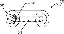
도 3a-c에 따르면, 본 개시의 다양한 형태들에 따른 몇몇의 노즐(350)이 도시되어 있다. 도 3a는 바디(355) 및 팁(360)을 포함하는 노즐(350)을 나타내며, 그러한 팁은 선택적으로 다수의 오리피스(365)를 갖춘다. 그 팁은 소정의 적절한 각도(Θ°)로 바디에 대해 비스듬히 각질 것이다. 예컨대, Θ는 약 5° 내지 약 85°의 범위, 예컨대 그 모든 범위 및 그 사이의 하위 범위들을 포함하여, 약 15° 내지 약 70°의 범위, 또는 약 30° 내지 약 60°의 범위가 될 것이다.According to Figures 3A-C,
도 3b는 도 3a의 라인 A-A에 따른 노즐(350)의 도면이다. 이러한 도면은 그 노즐의 팁(360)에 위치된 오리피스(365)들의 좀더 상세한 도면을 제공한다. 그러한 나타낸 실시예에 있어서, 팁은 6개의 오리피스를 포함한다. 그러나, 상기 팁은 2개 또는 그 이상의 오리피스, 3개 또는 그 이상의 오리피스, 4개 또는 그 이상의 오리피스, 5개 또는 그 이상의 오리피스, 6개 또는 그 이상의 오리피스, 7개 또는 그 이상의 오리피스, 또는 8개 또는 그 이상의 오리피스와 같이 보다 많거나 적은 오리피스를 포함할 수 있다는 것을 예상할 수 있을 것이다. 상기 노즐(350)들은 오리피스(365)들을 통해 다수의 가스 스트림을 근접한 박막 유리로 전달하기 위해 노즐의 바디 및 팁을 관통하는 도관(358)과 같은 적어도 하나의 도관을 더 포함한다.Figure 3B is a view of
도 3c는 적어도 본 실시예에서 팁의 원주를 따라 균일하게 간격된 오리피스들의 간격을 나타내는 노즐(350)의 상면도이다. 수, 간격, 및/또는 분배를 포함하는 다른 구성들이 가능하며 그 개시 시점의 범주 내에 속할 것이다. 또한 이들 도면은 일정한 기준으로 정해지지 않았으며, 소정 노들의 형태 및/또는 크기 및/또는 오리피스의 구성이 본 개시의 다른 형태들에 따라 채용될 수 있다는 것을 알아야 한다.3C is a top view of the
따라서, 그 개시 시점에 따른 노즐의 디자인 및 배치는 다수의 개구를 갖춘 적어도 일부의 노즐로 단일-개구 노즐을 교체함으로써 보다 큰 표면 영역에 걸쳐 상승력을 제공할 수 있다. 그러한 다수의 오리피스는 보다 큰 표면 영역에 걸쳐 상승력을 확산시키는 패턴에 다수의 가스 스트림을 제공한다. 예컨대, 유리 구조의 표면으로부터 1인치 정도로 가깝게 위치된 경우(설치 높이와 비슷한), 각각의 노즐은 약 1.5인치의 직경, 예컨대 약 0.5인치 내지 약 2인치의 직경을 갖는 영역에 걸쳐 상승력을 제공할 것이다. 유리 구조의 표면으로부터 2인치 정도로 가깝게 위치된 경우(성형 몰드 높이와 비슷한), 각각의 노즐은 약 4인치의 직경, 예컨대 약 2인치 내지 약 6인치의 직경을 갖는 영역에 걸쳐 상승력을 제공할 것이다. 다양한 실시예들에 따르면, 롤러 및 노즐 구성에 따라, 각 노즐로부터의 상승력은 유리 구조의 거의 전체 표면에 걸쳐 거의 연속의 커버 범위를 제공할 것이다.Thus, the design and placement of the nozzles at the start time can provide a lift force over a larger surface area by replacing the single-opening nozzle with at least some of the nozzles with multiple openings. Such multiple orifices provide multiple gas streams in a pattern that spreads the lift force over a larger surface area. For example, when positioned close to one inch from the surface of the glass structure (similar to the installation height), each nozzle provides a lift force over a region having a diameter of about 1.5 inches, such as about 0.5 inches to about 2 inches will be. When positioned close to two inches from the surface of the glass structure (similar to the mold height), each nozzle will provide a lift force over a region having a diameter of about 4 inches, such as about 2 inches to about 6 inches . According to various embodiments, depending on the roller and nozzle configuration, the lift force from each nozzle will provide a substantially continuous coverage over substantially the entire surface of the glass structure.
따라서, 본원에 개시된 상승 분사 어레이, 및 그와 같은 상승 분사 어레이를 채용하는 시스템 및 방법들은 또한 현재 시스템에 의해 성형된 것들보다 얇은 유리 구조를 성형하는데도 사용될 수 있다. 예컨대, 본원에 개시된 방법 및 시스템들은 약 0.3 mm 내지 약 3 mm의 범위, 예컨대 그 모든 범위 및 그 사이의 하위 범위를 포함하여, 약 0.5 mm 내지 약 2 mm의 범위, 또는 약 0.7 mm 내지 약 1.5 mm의 범위의 두께를 갖는 박막 유리 구조를 성형하는데 사용될 것이다. 선택적으로, 본원에 개시된 방법 및 시스템들은 두꺼운 유리 구조, 예컨대 약 4 mm보다 큰 두께, 또는 약 5 mm보다 큰 두께와 같이, 약 3 mm보다 큰 두께를 갖는 시트를 성형하는데 사용될 것이다.Thus, the elevated firing arrays, and systems and methods employing such raised firing arrays, can also be used to form thinner glass structures than those molded by current systems. For example, the methods and systems disclosed herein may be used in a range of about 0.5 mm to about 2 mm, or in a range of about 0.7 mm to about 1.5 mm, including all ranges and subranges therebetween, from about 0.3 mm to about 3 mm, lt; RTI ID = 0.0 > mm. < / RTI > Alternatively, the methods and systems disclosed herein may be used to form sheets having a thickness of greater than about 3 mm, such as thick glass structures, e.g., thicknesses greater than about 4 mm, or thicknesses greater than about 5 mm.
방법들Methods
본원에 개시된 방법들에 따르면, 유리 구조는 다수의 롤러를 포함하는 롤 컨베이어 상의 평면을 따라 이송되며, 그러한 다수의 롤러는 상기 평면에 거의 평행한 중심선을 갖는다. 소정의 실시예들에 있어서, 그러한 유리는 미리 결정된 평면을 따라 유리 구조를 이송하는 롤러들 상에 바로 배치될 것이다. 상기 평면은 예컨대 수평이지만, 원할 경우 소정의 다른 적절한 각도가 될 수도 있다.According to the methods disclosed herein, the glass structure is conveyed along a plane on a roll conveyor comprising a plurality of rollers, such that the plurality of rollers have a centerline substantially parallel to the plane. In certain embodiments, such glass will be placed directly on the rollers carrying the glass structure along a predetermined plane. The plane may be, for example, horizontal, but may be any other suitable angle as desired.
상기 유리 구조는 종래 알려진 소정의 방식으로 가열되는데, 예컨대 그 시트는 노 또는 다른 가열 장치를 거쳐 이송될 것이다. 선택적으로, 상기 롤 컨베이어 자체가 가열될 수 있다. 소정의 실시예들에 있어서, 그러한 유리는 시트가 새로운 형태로 효율적으로 몰딩될 수 있는 연화점으로 가열될 것이다. 다양한 실시예들에 따르면, 상기 유리 구조는 약 500℃ 내지 약 1000℃ 범위, 예컨대 그 모든 범위 및 그 사이의 하위 범위를 포함하여, 약 600℃ 내지 약 900℃ 범위, 또는 약 700℃ 내지 약 800℃ 범위의 온도로 가열될 것이다.The glass structure is heated in a manner known per se, for example the sheet will be transported through a furnace or other heating device. Optionally, the roll conveyor itself can be heated. In certain embodiments, such glass will be heated to a softening point at which the sheet can be efficiently molded into a new form. According to various embodiments, the glass structure has a temperature in the range of about 600 ° C to about 900 ° C, or in the range of about 700 ° C to about 800 ° C, including about 500 ° C to about 1000 ° C, Lt; 0 > C.
가열 후, 상기 유리 구조는 선택적으로 성형 몰드 아래의 위치로 이송될 것이다. 상기 성형 몰드는 특정 적용을 위한 성형 유리 제품을 생산하기에 적합한 소정의 형태 및 크기를 가질 것이다. 예를 들어, 그러한 성형 몰드는 유리 구조, 예컨대 자동차용 전면 유리 및 후면 유리창 또는 측면 유리창의 경우에 원하는 굴곡을 전달하도록 디자인될 것이다. 다른 형태 및 구성들이 예상되고 그러한 적용의 범주 내에 속할 것이다.After heating, the glass structure will optionally be transferred to a location below the mold. The forming mold will have a certain shape and size suitable for producing a molded glass article for a particular application. For example, such a molding mold will be designed to deliver a desired bend in the case of glass structures, such as automotive windshields and rear windshields or side windshields. Other forms and configurations are contemplated and will fall within the scope of such application.
다수의 노즐을 포함하는 상승 분사 어레이는 유리 구조 아래에 위치될 것이다. 이전에 나타낸 바와 같이, 예시의 유리 구조는 한정하진 않지만 몇가지 예를 들자면 하나의 유리 시트, 단일 스택의 다수의 유리 시트, 유리-유리 라미네이트 구조, 및 유리-폴리머 라미네이트 구조를 포함한다. 하나 또는 그 이상의 노즐은 롤 컨베이어로부터 유리 구조를 성형 몰드 쪽으로 그리고/또 그 위로 부상 및 상승시킬 수 있는 상향의 상승력을 제공하도록 가스 스트림이 유출되는 다수의 오리피스를 포함한다. 그러한 가스 스트림은 소정의 실시예들에서 가압된 공기를 포함하나, 원할 경우 그리고 한정하지 않고 불활성 가스와 같은 다른 적절한 가스 및 가스 혼합물을 포함할 수도 있다.The raised jet array comprising a plurality of nozzles will be positioned below the glass structure. As previously indicated, exemplary glass structures include, but are not limited to, one glass sheet, a plurality of glass sheets in a single stack, a glass-glass laminate structure, and a glass-polymer laminate structure. The one or more nozzles include a plurality of orifices through which the gas stream exits to provide an upward upward force that can lift and lift the glass structure from the roll conveyor toward and / or above the mold. Such gas streams include, but are not limited to, pressurized air in certain embodiments, and may include other suitable gas and gas mixtures such as inert gas.
다양한 실시예들에 따르면, 그러한 가스 유동은 단독으로 성형 몰드와 유리 구조가 접촉할 때까지 그 유리 구조를 상승시키기에 충분할 것이다. 다른 실시예들에 있어서, 상기 성형 몰드는 또한 롤 컨베이이에서 성형 몰드로의 유리 구조의 이동을 돕도록 진공이 제공되는 오리피스를 포함할 것이다. 그와 같은 경우, 좀더 강한 진공이 최초에 초기 지지를 제공하기 위해 인가되고, 이후 진공의 개구에서 유리 구조의 변형을 방지하기 위해 진공이 감소된다.According to various embodiments, such gas flow alone will be sufficient to raise the glass structure until the mold is in contact with the mold structure. In other embodiments, the forming mold will also include an orifice through which a vacuum is provided to assist movement of the glass structure from the roll conveyor to the forming mold. In such a case, a stronger vacuum is first applied to provide initial support, and then the vacuum is reduced to prevent deformation of the glass structure at the vacuum opening.
다양한 개시된 실시예들은 특정 실시예와 연계하여 기술된 특정 형태, 요소 또는 단계들을 포함한다는 것을 알아야 할 것이다. 또한, 특정 형태, 요소 또는 단계는, 하나의 특정 실시예와 연관되어 기술될 지라도, 다양한 기술되지 않은 조합 또는 변경의 다른 실시예들과 교환 또는 조합될 수 있다는 것을 알아야 할 것이다.It should be noted that the various disclosed embodiments include specific forms, elements or steps described in connection with the specific embodiments. It is also to be understood that a particular form, element, or step may be interchanged or combined with other embodiments of the various combinations or modifications not described in connection with one particular embodiment.
또한, 본원에 사용된 바와 같은 용어 "그", "하나", 또는 "한"은 "적어도 하나"를 의미하며, 다르게 반대로 특별히 나타내지 않는 한 "오직 하나"로 한정하지 않는다는 것을 알아야 할 것이다. 따라서, 예컨대 "하나의 노즐"은 다르게 그러한 문맥을 특별히 나타내지 않는 한 2개 또는 그 이상의 그와 같은 "노즐들"을 갖는 예들을 포함한다. 마찬가지로, "다수"는 "하나 이상"을 나타내기 위한 것이다. 그와 같이, "다수의 노즐"은 2개 또는 그 이상의 그와 같은 노즐, 3개 또는 그 이상의 그와 같은 노즐 등을 포함한다.It is also to be understood that the terms "the "," one ", or "an ", as used herein, means" at least one ", unless the context clearly dictates otherwise. Thus, for example, "one nozzle" includes examples having two or more such "nozzles ", unless otherwise specifically indicated such context. Likewise, "multiple" is intended to denote "more than one ". As such, a "plurality of nozzles" includes two or more such nozzles, three or more such nozzles, and the like.
범위들은 본원에서 "약" 하나의 특정치, 및/또는 "약" 또 다른 특정치로 표시될 수 있다. 그와 같은 범위가 표시될 때, 예들은 하나의 특정치부터 그리고/또 다른 특정치까지 포함한다. 유사하게, 그 앞에 "약"의 사용에 의해, 값들이 근사치로 표시될 경우, 그러한 특정치는 또 다른 범위를 형성한다는 것을 알아야 할 것이다. 더욱이, 각 범위의 끝점은 다른 끝점과 연계하여, 그리고 그 다른 끝점과 별개의 의미가 있다는 것을 알아야 할 것이다.Ranges may be expressed herein as "about" one particular characteristic, and / or "about" another specific value. When such a range is indicated, the examples include one particular characteristic and / or another characteristic. Similarly, it should be noted that if values are approximated by the use of "about" preceding them, then that particular value forms another range. Moreover, it should be noted that the endpoints of each range are associated with and are distinct from other endpoints.
달리 특별히 진술하지 않는 한, 본원에 기술된 방법은 단계들이 특정 순서로 수행되는 것을 요구하는 것으로 해석하려는 것은 아니다. 따라서, 여기서 방법 청구항은 실제로 그 단계들이 이어지는 순서로 열거하지 않거나 단계들이 특정 순서로 한정되는 청구항 또는 설명들에서 달리 특별히 진술하지 않으며, 소정의 특정 순서를 암시하려는 것은 아니다.Unless specifically stated otherwise, the methods described herein are not intended to be construed as requiring that the steps be performed in any particular order. Accordingly, the method claims herein are not intended to suggest any particular ordering, nor do they specifically dictate otherwise in the claims or the description where the steps are not actually listed in the following order or that the steps are in any particular order.
특정 실시예들의 다양한 형태, 요소 또는 단계들이 과도적인 표현 "포함하는"을 사용하여 개시되지만, 이는 과도적인 표현 "이루어지는" 또는 "본질적으로 ~로 이루어지는"을 사용하여 기술되는 것들을 포함한 다른 실시예들이 암시된다는 것을 알아야 할 것이다. 따라서, 예컨대 A+B+C를 포함하는 시스템에 암시된 다른 대안의 실시예들은 시스템이 A+B+C로 이루어지는 실시예 및 시스템이 본질적으로 A+B+C로 이루어지는 실시예들을 포함한다.While various forms, elements or steps of certain embodiments are disclosed using the transitional phrase "comprising ", it should be understood that other embodiments, including those described using transitional expressions" You should know that it is implied. Thus, other alternative embodiments implied in the system including, for example, A + B + C include embodiments in which the system consists of A + B + C and embodiments in which the system consists essentially of A + B + C.
통상의 기술자라면 다양한 변형 및 변경이 본 개시의 사상 및 범주를 벗어나지 않고 본 개시로 이루어질 수 있다는 것을 명확히 알 수 있을 것이다. 본 개시의 사상 및 본질을 포함하는 개시된 실시예들의 변형 조합, 부조합 및 변경들을 통상의 기술자들이 생각해 낼 수 있기 때문에, 본 개시는 부가된 청구항 및 그들 등가물의 범주 내의 모든 것들을 포함하는 것으로 해석될 것이다.It will be apparent to those skilled in the art that various modifications and variations can be made in the present disclosure without departing from the spirit or scope of the disclosure. It should be understood that this disclosure is to be construed to include all things within the scope of the appended claims and their equivalents, since modifications, subcombinations, and variations of the disclosed embodiments, including the spirit and scope of the disclosure, will be.
Claims (22)
(a) 평면을 따라 유리 구조를 이송하고, 상기 평면에 평행한 중심선을 갖는 다수의 롤러를 포함하는 롤 컨베이어;
(b) 다수의 오리피스를 갖춘 팁을 포함하는 다수의 노즐을 구비한 상승 분사 어레이; 및
(c) 성형 몰드를 포함하며,
상기 롤 컨베이어는 상기 상승 분사 어레이와 상기 성형 몰드 사이에 위치되고,
상기 상승 분사 어레이는 각각의 노즐 팁이 다수의 롤러의 중심선 상에 위치되도록 배치되는, 상승 분사형 부상 시스템.CLAIMS 1. A riser-type float system for forming a glass structure,
(a) a roll conveyor comprising a plurality of rollers conveying the glass structure along a plane and having a centerline parallel to the plane;
(b) an elevated jet array having a plurality of nozzles including a tip with a plurality of orifices; And
(c) a forming mold,
Wherein the roll conveyor is located between the raised jet array and the forming mold,
Wherein the raised spray array is positioned such that each nozzle tip is located on a centerline of the plurality of rollers.
유리 구조는 하나의 유리 시트, 단일 스택의 다수의 유리 시트, 유리-유리 라미네이트 구조, 및 유리-폴리머 라미네이트 구조를 포함하는 그룹에서 선택되는, 상승 분사형 부상 시스템.The method according to claim 1,
Wherein the glass structure is selected from the group consisting of a single glass sheet, a plurality of glass sheets in a single stack, a glass-glass laminate structure, and a glass-polymer laminate structure.
각각의 노즐은 2개 또는 그 이상의 오리피스를 포함하는, 상승 분사형 부상 시스템.The method according to claim 1 or 2,
Wherein each nozzle comprises two or more orifices.
각각의 노즐은 6개 또는 그 이상의 오리피스를 포함하는, 상승 분사형 부상 시스템.4. The method according to any one of claims 1 to 3,
Each nozzle comprising six or more orifices.
상승 분사 어레이의 다수의 노즐은 인접한 노즐과 다른 오리피스의 분배를 갖는, 상승 분사형 부상 시스템.5. The method according to any one of claims 1 to 4,
Wherein the plurality of nozzles of the raised jet array have a distribution of an orifice different from the adjacent nozzles.
상승 분사 어레이의 각 노즐의 각각의 오리피스를 통해 가스가 유동되도록, 상기 상승 분사 어레이에 연결된 가압 가스 소스를 더 포함하는, 상승 분사형 부상 시스템.6. The method according to any one of claims 1 to 5,
Further comprising a pressurized gas source coupled to the raised jet array such that gas flows through respective orifices of each nozzle of the raised jet array.
성형 몰드는 유리 구조에 대한 형태를 받아들이고 전달하기 위한 적어도 하나의 표면을 포함하는, 상승 분사형 부상 시스템.7. The method according to any one of claims 1 to 6,
Wherein the forming mold comprises at least one surface for accepting and delivering a shape for the glass structure.
성형 몰드는 진공이 제공되는 다수의 오리피스를 포함하는, 상승 분사형 부상 시스템.The method according to any one of claims 1 to 7,
Wherein the forming mold comprises a plurality of orifices provided with vacuum.
하나 또는 그 이상의 노즐은 수직 조절가능한, 상승 분사형 부상 시스템.The method according to any one of claims 1 to 8,
Wherein the one or more nozzles are vertically adjustable.
상승 분사 어레이는 상기 상승 분사 어레이를 둘러싸는 공간의 온도를 감소시키지 않고 수직 조절가능한, 상승 분사형 시스템.The method according to any one of claims 1 to 9,
Wherein the raised jet array is vertically adjustable without reducing the temperature of the space surrounding the raised jet array.
(a) 다수의 롤러를 포함하는 롤 컨베이어 상의 평면을 따라 유리 구조를 이송하는 단계 - 상기 다수의 롤러는 상기 평면에 평행한 중심선을 가짐;
(b) 상기 유리 구조를 가열하는 단계;
(c) 성형 몰드와 상승 분사 어레이간 롤 컨베이어 상에 상기 유리 구조를 위치시키는 단계; 및
(d) 상기 상승 분사 어레이의 각 오리피스로부터 가스 스트림을 유동시킴으로써 상기 롤 컨베이어로부터 상기 유리 구조를 상승시키는 단계를 포함하며,
상기 상승 분사 어레이는 다수의 오리피스를 갖춘 팁을 포함하는 다수의 노즐을 구비하고,
상기 상승 분사 어레이는 각각의 노즐 팁이 다수의 롤러의 중심선 상에 위치되도록 배치되며,
상기 가스 스트림은 상기 롤 컨베이어로부터 상기 유리 구조를 상승시키는 힘에 의해 유동되는, 유리 구조 성형 방법.A method for forming a glass structure,
(a) conveying a glass structure along a plane on a roll conveyor comprising a plurality of rollers, the plurality of rollers having a centerline parallel to the plane;
(b) heating the glass structure;
(c) positioning said glass structure on a roll conveyor between a forming mold and an elevated firing array; And
(d) raising the glass structure from the roll conveyor by flowing a gas stream from each orifice of the raised firing array,
Wherein the raised spray array comprises a plurality of nozzles including a tip with a plurality of orifices,
Wherein the raised spray array is arranged such that each nozzle tip is located on a centerline of the plurality of rollers,
Wherein the gas stream flows from the roll conveyor by a force to raise the glass structure.
유리 구조는 600℃ 내지 800℃ 범위의 온도로 가열되는, 유리 구조 성형 방법.The method of claim 11,
Wherein the glass structure is heated to a temperature in the range of 600 ° C to 800 ° C.
각각의 노즐은 2개 또는 그 이상의 오리피스를 포함하는, 유리 구조 성형 방법.12. The method according to claim 11 or 12,
Wherein each nozzle comprises two or more orifices.
각각의 노즐은 6개 또는 그 이상의 오리피스를 포함하는, 유리 구조 성형 방법.The method according to any one of claims 11 to 13,
Wherein each nozzle comprises six or more orifices.
가스 스트림 유동은 성형 몰드와의 접촉으로 롤 컨베이어로부터 유리 구조를 상승시키는 힘을 제공하는, 유리 구조 성형 방법.The method according to any one of claims 11 to 14,
Wherein the gas stream flow provides a force to lift the glass structure from the roll conveyor in contact with the forming mold.
성형 몰드는 유리 구조에 대한 형태를 받아들이고 전달하기 위한 적어도 하나의 표면을 포함하는, 유리 구조 성형 방법.The method according to any one of claims 11 to 15,
Wherein the forming mold comprises at least one surface for accepting and delivering a shape for the glass structure.
성형 몰드는 진공이 제공되는 다수의 오리피스를 포함하며, 상승 분사 어레이로부터의 가스 유동 및 성형 몰드로부터의 진공은 성형 몰드와의 접촉으로 롤 컨베이어로부터 유리 구조를 상승시키는 조합된 힘을 제공하는, 유리 구조 성형 방법.The method according to any one of claims 11 to 16,
The molding mold comprises a plurality of orifices provided with a vacuum and the gas flow from the raised injection array and the vacuum from the forming mold provide a combined force to raise the glass structure from the roll conveyor in contact with the molding mold. Structural molding method.
유리 구조는 0.7 mm 내지 1.5 mm 또는 0.3 mm 내지 1.5 mm 범위의 두께를 갖는, 유리 구조 성형 방법.The method according to any one of claims 11 to 17,
Wherein the glass structure has a thickness ranging from 0.7 mm to 1.5 mm or from 0.3 mm to 1.5 mm.
(a) 평면을 따라 유리 구조를 이송하고, 상기 평면에 평행한 중심선을 갖는 다수의 롤러를 포함하는 롤 컨베이어; 및
(b) 다수의 오리피스를 갖춘 팁을 포함하는 다수의 노즐을 구비한 각각의 상승 노즐 어레이를 포함하며,
각각의 노즐 팁은 상기 다수의 롤러의 중심선 상에 위치되는, 시스템.A system for raising or shaping a glass structure,
(a) a roll conveyor comprising a plurality of rollers conveying the glass structure along a plane and having a centerline parallel to the plane; And
(b) a respective raised nozzle array having a plurality of nozzles including a tip with a plurality of orifices,
Each nozzle tip being located on a centerline of the plurality of rollers.
상승 노즐 어레이 및 롤 컨베이어 상에 위치된 성형 몰드를 더 포함하는, 시스템.The method of claim 19,
A rising nozzle array and a forming mold positioned on the roll conveyor.
상승 노즐 어레이의 하나 또는 그 이상의 노즐은 수직 조절가능한, 시스템.The method of claim 19 or 20,
Wherein one or more nozzles of the riser nozzle array are vertically adjustable.
상승 노즐 어레이는 상기 상승 노즐 어레이를 둘러싸는 공간의 온도를 감소시키지 않고 수직 조절가능한, 시스템.The method according to any one of claims 19 to 21,
Wherein the lift nozzle array is vertically adjustable without reducing the temperature of the space surrounding the lift nozzle array.
Applications Claiming Priority (3)
| Application Number | Priority Date | Filing Date | Title |
|---|---|---|---|
| US201461972784P | 2014-03-31 | 2014-03-31 | |
| US61/972,784 | 2014-03-31 | ||
| PCT/US2015/022995 WO2015153342A1 (en) | 2014-03-31 | 2015-03-27 | Method and lift jet floatation system for shaping thin glass |
Publications (1)
| Publication Number | Publication Date |
|---|---|
| KR20160138485A true KR20160138485A (en) | 2016-12-05 |
Family
ID=52875791
Family Applications (1)
| Application Number | Title | Priority Date | Filing Date |
|---|---|---|---|
| KR1020167029629A KR20160138485A (en) | 2014-03-31 | 2015-03-27 | Method and lift jet floatation system for shaping thin glass |
Country Status (7)
| Country | Link |
|---|---|
| US (2) | US9573833B2 (en) |
| EP (1) | EP3126300B1 (en) |
| JP (1) | JP2017511293A (en) |
| KR (1) | KR20160138485A (en) |
| CN (1) | CN106573815A (en) |
| TW (1) | TWI667209B (en) |
| WO (1) | WO2015153342A1 (en) |
Families Citing this family (28)
| Publication number | Priority date | Publication date | Assignee | Title |
|---|---|---|---|---|
| US10035331B2 (en) | 2011-06-24 | 2018-07-31 | Corning Incorporated | Light-weight hybrid glass laminates |
| US9616641B2 (en) | 2011-06-24 | 2017-04-11 | Corning Incorporated | Light-weight hybrid glass laminates |
| US10596783B2 (en) | 2012-05-31 | 2020-03-24 | Corning Incorporated | Stiff interlayers for laminated glass structures |
| EP2858820B1 (en) | 2012-06-01 | 2018-06-13 | Corning Incorporated | Glass laminate construction for optimized breakage performance |
| EP2861542A1 (en) | 2012-06-14 | 2015-04-22 | Corning Incorporated | Process for laminating thin glass laminates |
| EP2679551A1 (en) | 2012-06-28 | 2014-01-01 | Corning Incorporated | Process and system for fine tuning precision glass sheet bending |
| CN105339316B (en) | 2013-02-25 | 2018-11-09 | 康宁股份有限公司 | The method for manufacturing thin glass block |
| EP3511161A1 (en) | 2013-08-26 | 2019-07-17 | Corning Incorporated | Laminate structure |
| CN105682921B (en) | 2013-08-30 | 2018-10-19 | 康宁股份有限公司 | Lightweight, the glass laminated structure of high rigidity |
| US10800143B2 (en) | 2014-03-07 | 2020-10-13 | Corning Incorporated | Glass laminate structures for head-up display system |
| US9573833B2 (en) * | 2014-03-31 | 2017-02-21 | Corning Incorporated | Method and lift jet floatation system for shaping thin glass |
| CN107074010B (en) | 2014-07-10 | 2020-08-25 | 康宁股份有限公司 | Cold formed glass trim |
| EP3174836B1 (en) | 2014-08-01 | 2020-08-19 | Corning Incorporated | Glass shaping apparatus and method |
| EP3212583A2 (en) | 2014-10-29 | 2017-09-06 | Corning Incorporated | Apparatus and method for shaping heated glass sheets |
| WO2016073808A1 (en) | 2014-11-07 | 2016-05-12 | Corning Incorporated | Induction heating method and apparatus for shaping thin glass |
| US10379265B2 (en) | 2015-05-11 | 2019-08-13 | Corning Incorporated | Surface display units with opaque screen |
| KR20180016431A (en) | 2015-06-02 | 2018-02-14 | 코닝 인코포레이티드 | Multifunctional material system for surface display units |
| JP6847862B2 (en) | 2015-06-02 | 2021-03-24 | コーニング インコーポレイテッド | Photoresponsive thin glass laminate |
| CN111761893B (en) | 2015-07-10 | 2023-05-30 | 康宁股份有限公司 | Cold formed laminate |
| US10350861B2 (en) | 2015-07-31 | 2019-07-16 | Corning Incorporated | Laminate structures with enhanced damping properties |
| US9809485B2 (en) * | 2015-11-02 | 2017-11-07 | Glasstech, Inc. | Lift device for a glass processing system |
| CN107176787B (en) * | 2017-06-29 | 2023-05-12 | 东旭光电科技股份有限公司 | Roller for float glass annealing process, float glass conveying device and conveying method |
| CN113631524B (en) * | 2018-12-13 | 2023-04-11 | 康宁公司 | Conveying apparatus and conveying belt |
| US11485668B2 (en) | 2019-08-09 | 2022-11-01 | Ford Global Technologies, Llc | Glass form and marking |
| US11753347B2 (en) * | 2019-10-14 | 2023-09-12 | Corning Incorporated | Rapid forming of glass and ceramics |
| CN111018335B (en) * | 2019-12-25 | 2022-08-02 | 中国建材国际工程集团有限公司 | Glass taking and distributing system and method for float glass production line |
| JP7450851B2 (en) * | 2020-02-25 | 2024-03-18 | 日本電気硝子株式会社 | Glass film manufacturing method |
| CN115557251A (en) * | 2022-10-14 | 2023-01-03 | 蚌埠高华电子股份有限公司 | Pneumatic auxiliary conduction equipment and method for vacuum coated glass |
Family Cites Families (57)
| Publication number | Priority date | Publication date | Assignee | Title |
|---|---|---|---|---|
| US1960222A (en) | 1930-10-22 | 1934-05-22 | Saint Gobain | Manufacture of tempered glass |
| JPS5549162A (en) | 1978-10-03 | 1980-04-09 | Ikeuchi:Kk | Mist producting device |
| FI76315C (en) | 1986-10-29 | 1988-10-10 | Kyro Oy | Apparatus in the cooling compartment for a glass curing plant |
| US4767437A (en) | 1987-03-25 | 1988-08-30 | Ppg Industries, Inc. | Horizontal press bending using a splitting vacuum/pressure pickup |
| DE4002546C2 (en) | 1990-01-29 | 1994-07-14 | Wsp Ingenieurgesellschaft Fuer | High-convection gas jet nozzle section for flat material guided over rollers, and method for their operation |
| US5147439A (en) | 1990-05-01 | 1992-09-15 | Glasstech, Inc. | Variable pressure gas jet system for lifting and forming glass sheets |
| JPH04219334A (en) * | 1990-12-20 | 1992-08-10 | Asahi Glass Co Ltd | Forming device of plate-like body and bending method |
| US5286271A (en) * | 1992-07-02 | 1994-02-15 | Ppg Industries, Inc. | Method and apparatus for bending glass sheets |
| US5403369A (en) | 1993-09-13 | 1995-04-04 | Glasstech, Inc. | Apparatus and method for positioning glass sheets |
| US5507852A (en) | 1994-01-07 | 1996-04-16 | Ppg Industries, Inc. | Glass sheet quench |
| FI104422B (en) | 1998-06-30 | 2000-01-31 | Tamglass Ltd Oy | Method and apparatus for curing glass sheets |
| JP3717339B2 (en) * | 1999-07-26 | 2005-11-16 | セントラル硝子株式会社 | Glass plate bending equipment |
| JP2001158631A (en) | 1999-11-30 | 2001-06-12 | Central Glass Co Ltd | Method for curving and molding glass plate |
| US6505483B1 (en) | 2000-02-25 | 2003-01-14 | Surface Combustion, Inc. | Glass transportation system |
| DE10045479A1 (en) | 2000-09-14 | 2002-04-04 | Schott Glas | Method and device for contactless storage and transportation of flat glass |
| JP2002173332A (en) | 2000-12-07 | 2002-06-21 | Asahi Glass Co Ltd | Air jetting nozzle and air floating apparatus for glass plate |
| JP4064740B2 (en) * | 2002-06-24 | 2008-03-19 | セントラル硝子株式会社 | Method and apparatus for bending glass plate |
| JP2004051404A (en) | 2002-07-18 | 2004-02-19 | Asahi Glass Co Ltd | Bend-forming apparatus for glass plate |
| DE10314408A1 (en) | 2003-03-28 | 2004-10-07 | Pilkington Automotive Deutschland Gmbh | Device for generating a gas cushion |
| GB0406545D0 (en) | 2004-03-23 | 2004-04-28 | Pilkington Plc | Tempering of glass |
| US7908885B2 (en) | 2004-11-08 | 2011-03-22 | New Way Machine Components, Inc. | Non-contact porous air bearing and glass flattening device |
| US7958750B2 (en) | 2005-10-21 | 2011-06-14 | Glasstech, Inc. | Glass sheet forming system |
| JP5095622B2 (en) * | 2005-10-24 | 2012-12-12 | グラステック インコーポレイテッド | Glass sheet lift jet nozzle movement and job switching |
| US20120094084A1 (en) | 2010-10-15 | 2012-04-19 | William Keith Fisher | Chemically-strengthened glass laminates |
| US8986072B2 (en) | 2011-05-26 | 2015-03-24 | Corning Incorporated | Methods of finishing an edge of a glass sheet |
| US9616641B2 (en) | 2011-06-24 | 2017-04-11 | Corning Incorporated | Light-weight hybrid glass laminates |
| US10035331B2 (en) | 2011-06-24 | 2018-07-31 | Corning Incorporated | Light-weight hybrid glass laminates |
| TWI572480B (en) | 2011-07-25 | 2017-03-01 | 康寧公司 | Laminated and ion-exchanged strengthened glass laminates |
| JP2015501274A (en) | 2011-10-10 | 2015-01-15 | コーニング インコーポレイテッド | Apparatus and method for forming a bend without slack in a thin glass sheet |
| WO2013063207A1 (en) | 2011-10-28 | 2013-05-02 | Corning Incorporated | Glass articles with infrared reflectivity and methods for making the same |
| US8816252B2 (en) | 2011-11-22 | 2014-08-26 | Corning Incorporated | Methods and apparatus for localized heating and deformation of glass sheets |
| US8549885B2 (en) | 2011-11-23 | 2013-10-08 | Corning Incorporated | Process and system for precision glass sheet bending |
| US20130127202A1 (en) | 2011-11-23 | 2013-05-23 | Shandon Dee Hart | Strengthened Glass and Glass Laminates Having Asymmetric Impact Resistance |
| US10596783B2 (en) | 2012-05-31 | 2020-03-24 | Corning Incorporated | Stiff interlayers for laminated glass structures |
| US8789392B2 (en) | 2012-05-31 | 2014-07-29 | Corning Incorporated | Apparatus for shaping glass and methods |
| US8962084B2 (en) | 2012-05-31 | 2015-02-24 | Corning Incorporated | Methods of applying a layer of material to a non-planar glass sheet |
| EP2858820B1 (en) | 2012-06-01 | 2018-06-13 | Corning Incorporated | Glass laminate construction for optimized breakage performance |
| US20150140301A1 (en) | 2012-06-08 | 2015-05-21 | Corning Incorporated | Laminated glass structures having high glass to polymer interlayer adhesion |
| US20150122406A1 (en) | 2012-06-08 | 2015-05-07 | Corning Incorporated | Process for laminating thin glass laminates |
| EP2861542A1 (en) | 2012-06-14 | 2015-04-22 | Corning Incorporated | Process for laminating thin glass laminates |
| EP2679551A1 (en) | 2012-06-28 | 2014-01-01 | Corning Incorporated | Process and system for fine tuning precision glass sheet bending |
| US9387651B2 (en) | 2012-09-26 | 2016-07-12 | Corning Incorporated | Methods for producing ion exchanged glass and resulting apparatus |
| US20140087193A1 (en) | 2012-09-26 | 2014-03-27 | Jeffrey Scott Cites | Methods for producing ion exchanged glass and resulting apparatus |
| JP6079789B2 (en) * | 2013-01-11 | 2017-02-15 | 旭硝子株式会社 | Method and apparatus for producing tempered glass |
| CN105339316B (en) | 2013-02-25 | 2018-11-09 | 康宁股份有限公司 | The method for manufacturing thin glass block |
| CN105408109A (en) | 2013-04-22 | 2016-03-16 | 康宁股份有限公司 | Laminated glass structures having high glass to polymer interlayer adhesion |
| EP3461797A1 (en) | 2013-07-16 | 2019-04-03 | Corning Incorporated | Method for bending thin glass |
| US20160207819A1 (en) | 2013-08-26 | 2016-07-21 | Corning Incorporated | Methods for localized annealing of chemically strengthened glass |
| EP3511161A1 (en) | 2013-08-26 | 2019-07-17 | Corning Incorporated | Laminate structure |
| CN105705330B (en) | 2013-08-29 | 2019-06-04 | 康宁股份有限公司 | Thin glass layer laminated structure |
| CN105682921B (en) | 2013-08-30 | 2018-10-19 | 康宁股份有限公司 | Lightweight, the glass laminated structure of high rigidity |
| US20160250825A1 (en) | 2013-10-07 | 2016-09-01 | Corning Incorporated | Glass laminate structures having improved edge strength |
| US20150158275A1 (en) | 2013-12-10 | 2015-06-11 | Corning Incorporated | Non-yellowing glass laminate structure |
| US20150232366A1 (en) | 2014-02-18 | 2015-08-20 | Corning Incorporated | Tunable mold system for glass press bending equipment |
| US20150232367A1 (en) | 2014-02-18 | 2015-08-20 | Corning Incorporated | Press bending mold cloth change system and method |
| US20150251377A1 (en) | 2014-03-07 | 2015-09-10 | Corning Incorporated | Glass laminate structures for head-up display system |
| US9573833B2 (en) * | 2014-03-31 | 2017-02-21 | Corning Incorporated | Method and lift jet floatation system for shaping thin glass |
-
2015
- 2015-03-25 US US14/668,245 patent/US9573833B2/en active Active
- 2015-03-26 US US14/669,017 patent/US20150274571A1/en not_active Abandoned
- 2015-03-27 CN CN201580027584.4A patent/CN106573815A/en active Pending
- 2015-03-27 KR KR1020167029629A patent/KR20160138485A/en not_active Application Discontinuation
- 2015-03-27 JP JP2016560481A patent/JP2017511293A/en active Pending
- 2015-03-27 EP EP15716935.0A patent/EP3126300B1/en not_active Not-in-force
- 2015-03-27 WO PCT/US2015/022995 patent/WO2015153342A1/en active Application Filing
- 2015-03-30 TW TW104110307A patent/TWI667209B/en not_active IP Right Cessation
Also Published As
| Publication number | Publication date |
|---|---|
| WO2015153342A1 (en) | 2015-10-08 |
| JP2017511293A (en) | 2017-04-20 |
| EP3126300A1 (en) | 2017-02-08 |
| TW201544464A (en) | 2015-12-01 |
| EP3126300B1 (en) | 2018-12-26 |
| CN106573815A (en) | 2017-04-19 |
| US9573833B2 (en) | 2017-02-21 |
| US20150274571A1 (en) | 2015-10-01 |
| US20150274575A1 (en) | 2015-10-01 |
| TWI667209B (en) | 2019-08-01 |
Similar Documents
| Publication | Publication Date | Title |
|---|---|---|
| KR20160138485A (en) | Method and lift jet floatation system for shaping thin glass | |
| CA2625666C (en) | Glass sheet forming system and method | |
| US4578103A (en) | Glass sheet processing system including topside transfer apparatus | |
| US20100180638A1 (en) | System for positioning glass sheets for forming | |
| EP2351713B1 (en) | Air-cool intensifying apparatus for glass plate, and air-cool intensifying method | |
| JP2003523916A (en) | Glass transfer system | |
| US7665331B2 (en) | Method and machine for the production of convex glass sheets | |
| US11021387B2 (en) | Manufacturing method for laminated glass | |
| CN207435301U (en) | A kind of single-curved surface curved tempered glass former | |
| WO2007083532A1 (en) | Process for producing formed glass | |
| ITMI972771A1 (en) | PROCEDURE AND EQUIPMENT FOR BENDING MATERIAL IN HEAT-ROLLABLE SHEET IN PARTICULAR GLASS SHEETS | |
| JPH02503309A (en) | Glass plate tempering method and device | |
| CN108545913B (en) | Spherical toughened glass production device and method | |
| US4586946A (en) | Equipment for curving glass sheets | |
| EP0062814A1 (en) | Apparatus for curving and tempering or heat toughening thin glass sheets | |
| JPH10338532A (en) | Production of tempered glass sheet and apparatus for production therefor | |
| CN108623139A (en) | Thermal current conveying device and method in heating-furnace | |
| EP1843983A2 (en) | Apparatus and method for glass sheet quenching | |
| US11739020B2 (en) | Conveying apparatus and methods for conveying ribbon | |
| CN110167893A (en) | Glass sheet forming method and the forming of glass production line used in the manufacturing process | |
| JP2001158631A (en) | Method for curving and molding glass plate | |
| US4074995A (en) | Method of shaping glass sheets by the roll forming method | |
| JPH11147728A (en) | Bending formation of glass plate and apparatus therefor | |
| CN102515492A (en) | Tempered glass plate cooling method and wind grating adopting the same |
Legal Events
| Date | Code | Title | Description |
|---|---|---|---|
| WITB | Written withdrawal of application |