KR20160137726A - Head curvature reflected, reversed curve arch shape dry electrodes for multichannel EEG - Google Patents
Head curvature reflected, reversed curve arch shape dry electrodes for multichannel EEG Download PDFInfo
- Publication number
- KR20160137726A KR20160137726A KR1020150070451A KR20150070451A KR20160137726A KR 20160137726 A KR20160137726 A KR 20160137726A KR 1020150070451 A KR1020150070451 A KR 1020150070451A KR 20150070451 A KR20150070451 A KR 20150070451A KR 20160137726 A KR20160137726 A KR 20160137726A
- Authority
- KR
- South Korea
- Prior art keywords
- electrode
- eeg
- head
- concave arcuate
- curvature
- Prior art date
- Legal status (The legal status is an assumption and is not a legal conclusion. Google has not performed a legal analysis and makes no representation as to the accuracy of the status listed.)
- Granted
Links
Images


Classifications
-
- A61B5/0478—
Landscapes
- Measurement And Recording Of Electrical Phenomena And Electrical Characteristics Of The Living Body (AREA)
Abstract
두상 곡률을 반영한 다채널 오목 아치형 건식 뇌파 전극이 개시된다. 오목 아치형상으로 형성되어 기 설정된 간격으로 이격된 5개의 제1 전극, 제1 전극을 지지하고, 적어도 하나의 관통구가 형성되며, 하부에 초단회로가 부착되는 제2 전극을 포함한다.A multi-channel concave arcuate dry EEG electrode reflecting the curvature of the head is disclosed. And a second electrode which is formed in a concave-arch shape and supports five first electrodes and a first electrode spaced apart at predetermined intervals, at least one through-hole is formed, and a first circuit is attached to a lower portion.
Description
본 발명은 건식 뇌파 전극에 관한 것으로, 보다 상세하게는 두상 곡률을 반영한 다채널 오목 아치형 건식 뇌파 전극에 관한 것이다.
The present invention relates to a dry EEG electrode, and more particularly, to a multi-channel concave arcuate EEG electrode that reflects curvature of head.
사람의 뇌는 다양한 활동에 따라 특정 부위에서 활성화가 일어난다. 예를 들어, 사람이 팔을 움직이거나 하는 행동을 하면 운동 중추를 담당하는 뇌의 영역에서 활성화가 일어나며, 이러한 반응은 뇌전도(EGG), fMRI, MEG, NIRs 같은 방법으로 측정이 가능하다. 이 중에 뇌전파(뇌파) 신호는 두피에 전기 신호를 측정할 수 있는 전극을 부착하여 뇌의 활성화를 측정하는 방법이다.
The human brain is activated at specific sites according to various activities. For example, when a person moves his or her arm, activation occurs in the area of the brain responsible for the motor center, and the response can be measured by means of EGG, fMRI, MEG, or NIRs. Among these, the brain wave (EEG) signal is a method of measuring the activation of the brain by attaching an electrode capable of measuring an electric signal to the scalp.
종래 건식 뇌파 전극의 경우, 뇌파 측정 시 방해가 되는 머리카락의 장벽을 극복하기 위해 손가락(finger) 또는 스파이크(spike) 형상으로 설계가 되었다. 하지만 이러한 형태의 구조는 머리카락의 장벽을 극복하기엔 좋은 구조이지만 뇌파를 측정하기엔 여전히 단점이 존재한다.In the case of the conventional dry EEG electrode, a finger or a spike shape is designed to overcome a barrier of the hair which is disturbed in EEG measurement. However, this type of structure is a good structure to overcome the barriers of hair, but there are still disadvantages to measure EEG.
첫 번째, 손가락 또는 스파이크 형상은 두피와 전극이 실제로 닿는 면적이 구조적으로 제한적이다. 하지만 접촉 면적이 적다는 것은 전극과 피부간의 임피던스를 증가시키는 주요한 원인이 되며, 임피던스의 증가는 측정되는 뇌파 신호의 질이 낮추는 부작용이 있다. 두 번째로, 손가락 또는 스파이크 형상의 구조는 사용자의 두피를 자극하여 사용자가 불편을 느낄 수 있다. 세 번째로, 다채널 뇌파 측정을 위해 다량의 전극을 사용해야 하는 상황에서 발생한다.
First, the shape of the finger or spike is structurally limited in the area that the scalp and the electrode actually touch. However, a small contact area is a major cause of increasing the impedance between the electrode and the skin, and the increase in impedance has a side effect of lowering the quality of the measured EEG signal. Second, the structure of the finger or spike shape stimulates the user ' s scalp so that the user can feel inconvenience. Third, it occurs in a situation where a large number of electrodes must be used for multi-channel EEG measurement.
다채널 뇌파 측정은 국제적 표준인 10 ~ 20 국제체계기준에 따라 전극을 머리에 위치시킨다. 다채널 뇌파 측정을 위해선 다량의 전극을 동시에 사용해야 하는데 종래의 경우 한 개의 전극을 모든 채널에 동일하게 사용하고 있다. 하지만 해부학적 근거에 따르면 두상은 각 위치마다 다른 곡률을 가지고 있다. 그래서 각 위치마다 다른 곡률을 가진 두상의 굴곡을 반영하여 전극을 설계해야 하지만 종래의 기술들은 하나의 전극을 모든 부위에 사용하고 있다.Multichannel EEG measurements place the electrodes at the head according to the international standard 10-20 International System Standards. In order to measure multi-channel EEG, a large number of electrodes must be used at the same time. In the conventional case, one electrode is used for all channels equally. However, according to the anatomical evidence, the head has different curvature for each position. Therefore, it is necessary to design the electrode to reflect the curvature of the head with different curvature at each position, but conventional techniques use one electrode for all parts.
따라서, 상기 문제점을 해결할 수 있는 전극을 개발이 필요한 실정이다.
Therefore, it is necessary to develop an electrode capable of solving the above problems.
본 발명이 이루고자 하는 과제는 머리카락의 방해요인을 효과적으로 극복하고 두상의 굴곡을 반영하는 두상 곡률을 반영한 다채널 오목 아치형 건식 뇌파 전극을 제공한다.SUMMARY OF THE INVENTION The present invention provides a multi-channel concave arcuate dry EEG electrode that effectively overcomes obstacles to hair and reflects the curvature of the head that reflects the curvature of the head.
본 발명이 이루고자 하는 다른 과제는 두피와의 접촉 면적을 최대한으로 높임으로써, 전극과 두피와의 임피던스를 낮추어 신호의 SNR(signal to ratio)을 높이는 두상 곡률을 반영한 다채널 오목 아치형 건식 뇌파 전극을 제공한다.
Another problem to be solved by the present invention is to provide a multi-channel concave arcuate dry EEG electrode that maximizes the contact area with the scalp and reflects the curvature of the head to lower the impedance between the electrode and the scalp to increase the signal to ratio (SNR) do.
상기 목적을 달성하기 위해,In order to achieve the above object,
본 발명에 따른 두상 곡률을 반영한 다채널 오목 아치형 건식 뇌파 전극은,The multi-channel concave arcuate dry EEG electrode reflecting the curvature of the head according to the present invention,
오목 아치형상으로 형성되어 기 설정된 간격으로 이격된 5개의 제1 전극, 상기 제1 전극을 지지하고, 적어도 하나의 관통구가 형성되며, 하부에 초단회로가 부착되는 제2 전극을 포함한다.Five first electrodes formed in a concave-arch shape and spaced apart at predetermined intervals, a second electrode supporting the first electrode, at least one through-hole being formed, and a second circuit being attached at the bottom.
상기 제1 전극은, 사람 두상의 굴곡을 기초로 상기 오목 아치형상을 형성하는 것을 특징으로 한다.Wherein the first electrode forms the concave arch shape on the basis of the curvature of the human head.
상기 제1 전극은, 머리카락의 양에 따라 높이 조절을 하는 것을 특징으로 한다.
The first electrode is characterized in that the height of the first electrode is adjusted according to the amount of the hair.
본 발명에 따른 두상 곡률을 반영한 다채널 오목 아치형 건식 뇌파 전극에 의하면, 머리카락의 방해요인을 효과적으로 극복하고 두상의 굴곡을 반영할 수 있다.According to the multi-channel concave arcuate dry EEG electrode reflecting the curvature of the head according to the present invention, it is possible to effectively overcome obstacles of the hair and to reflect the curvature of the head.
또한 두피와의 접촉 면적을 최대한으로 높임으로써, 전극과 두피와의 임피던스를 낮추어 신호의 SNR(signal to ratio)을 높일 수 있다.
In addition, by maximizing the contact area with the scalp, the signal to noise ratio (SNR) of the signal can be increased by lowering the impedance between the electrode and the scalp.
도 1은 본 발명에 일 실시예에 따른 다채널 오목 아치형 건식 뇌파 전극을 설명하기 위한 도면이다.
도 2는 본 발명에 일 실시예에 따른 다채널 오목 아치형 건식 뇌파 전극의 부착 위치를 설명하기 위한 도면이다.
도 3은 본 발명에 일 실시예에 따른 다채널 오목 아치형 건식 뇌파 전극을 실질적으로 부착한 모습을 설명하기 위한 도면이다.
도 4는 본 발명에 일 실시예에 따른 다채널 오목 아치형 건식 뇌파 전극의 성능을 설명하기 위한 도면이다.1 is a view for explaining a multi-channel concave arcuate dry EEG electrode according to an embodiment of the present invention.
2 is a view for explaining an attachment position of a multi-channel concave arcuate dry EEG electrode according to an embodiment of the present invention.
FIG. 3 is a view illustrating a multi-channel concave arcuate dry EEG electrode according to an embodiment of the present invention. Referring to FIG.
4 is a view for explaining the performance of a multi-channel concave arcuate dry EEG electrode according to an embodiment of the present invention.
이하 본 발명의 실시예를 첨부된 도면들을 참조하여 상세히 설명한다. 우선 각 도면의 구성요소들에 참조부호를 부가함에 있어서, 동일한 구성요소들에 대해서는 비록 다른 도면상에 표시되더라도 가능한 한 동일한 부호를 가지도록 하고 있음에 유의한다. 또한 본 발명을 설명함에 있어, 관련된 공지 구성 또는 기능에 대한 구체적인 설명이 당업자에게 자명하거나 본 발명의 요지를 흐릴 수 있다고 판단되는 경우에는 그 상세한 설명은 생략한다.
Hereinafter, embodiments of the present invention will be described in detail with reference to the accompanying drawings. In the drawings, the same reference numerals as used in the appended drawings denote like elements, unless indicated otherwise. In the following description of the present invention, a detailed description of known functions and configurations incorporated herein will be omitted when it may make the subject matter of the present invention rather obvious or understandable to those skilled in the art.
도 1은 본 발명에 일 실시예에 따른 다채널 오목 아치형 건식 뇌파 전극을 설명하기 위한 도면이다. 도 1(a)는 다채널 오목 아치형 건식 뇌파 전극을 도시한 사시도이고, 도 1(b)는 다채널 오목 아치형 건식 뇌파 전극을 도시한 정면도이며, 도 1(c)는 다채널 오목 아치형 건식 뇌파 전극을 도시한 측면도이다.1 is a view for explaining a multi-channel concave arcuate dry EEG electrode according to an embodiment of the present invention. FIG. 1 (b) is a front view showing a multi-channel concave arcuate dry EEG electrode. FIG. 1 (c) is a front view showing a multi-channel concave arcuate dry EEG Fig.
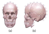
도 2는 본 발명에 일 실시예에 따른 다채널 오목 아치형 건식 뇌파 전극의 부착 위치를 설명하기 위한 도면이다. 도 2(a)는 다채널 오목 아치형 건식 뇌파 전극을 얼굴 정면에서 부착하는 모습을 도시한 도면이고, 도 2(b)는 다채널 오목 아치형 건식 뇌파 전극을 얼굴 측면에서 부착하는 모습을 도시한 도면이다.2 is a view for explaining an attachment position of a multi-channel concave arcuate dry EEG electrode according to an embodiment of the present invention. FIG. 2 (a) is a view showing a state in which a multi-channel concave arcuate dry EEG electrode is attached to the front of the face, and FIG. 2 (b) to be.
도 1 내지 도 2를 참조하면, 다채널 오목 아치형 건식 뇌파 전극(1)은 머리카락의 방해요인을 효과적으로 극복하고, 두상의 굴곡을 반영하여 효율적으로 뇌파를 측정할 수 있다. 다채널 오목 아치형 건식 뇌파 전극(1)은 머리카락 결을 효과적으로 투과하면서 두피와의 접촉 면적을 최대한으로 높일 수 있다. 이를 통해, 전극과 두피와의 임피던스를 낮추어 신호의 SNR(signal to ratio)을 높일 수 있다.
Referring to FIGS. 1 and 2, the multi-channel concave arcuate
다채널 오목 아치형 건식 뇌파 전극(1)은 제1 전극과 제2 전극을 포함한다. The multi-channel concave arcuate
제1 전극은 오목 아치형상으로 형성되어 기 설정된 간격으로 이격된 5개를 포함한다. 즉, 제1 전극은 일렬로 배치된 오목 아치형상의 구조물이다. The first electrode includes five electrodes formed in a concave-arch shape and spaced at predetermined intervals. That is, the first electrode is a concave arcuate structure arranged in a line.
제1 전극은 뇌파 측정 시, 가장 장애가 되는 머리카락을 효과적으로 극복하기 위해 구조물의 두께 및 간격이 설계되었다. 제1 전극은 두피에 부착 시 오목 아치형상의 구조물 사이사이로 머리카락들이 끼어 들어가게 되어 머리카락의 방해가 최소화되도록 구현되었다. 제1 전극은 두상의 굴곡을 반영하기 위해 오목 아치형상의 구조로 설계되었으며, 이는 두피와 전극의 접촉면적을 최대화할 수 있는 효과가 있다.In the first electrode, the structure thickness and spacing were designed to effectively overcome the hair that is the most troublesome in EEG measurement. When the first electrode is attached to the scalp, the hair is interposed between the concave arcuate structures, thereby minimizing the interference of the hair. The first electrode is designed to have a concave arcuate shape in order to reflect the bending of the head, which has the effect of maximizing the contact area between the scalp and the electrode.
특히, 제1 전극은 머리카락이 상대적으로 많은 부위에 대해서는 뇌파 측정을 용이하게 하기 위해 오목 아치형상의 구조물 높이를 높일 수 있다.
In particular, the height of the concave-arcuate structure of the first electrode can be increased to facilitate EEG measurement in a region where the hair is relatively large.
제2 전극은 제1 전극을 지지하고, 초단회로가 부착된다. 제2 전극은 제1 전극에서 측정된 뇌파 신호를 초단회로를 거쳐 전달된다. 제2 전극은 하부에 상기 초단회로를 부착하며, 이를 용이하게 하기 위해 적어도 하나의 관통구를 포함할 수 있다.The second electrode supports the first electrode, and a first stage circuit is attached. The second electrode transmits the EEG signal measured at the first electrode through the first circuit. The second electrode may include at least one through-hole to facilitate attachment of the first-stage circuit to the bottom.
바람직하게는, 제2 전극의 하면은 평평하게 설계가 되어 초단회로가 쉽게 부착할 수 있도록 하며, 4개의 관통구가 형성되어 제1 전극에서 측정된 뇌파신호가 초단회로의 입력으로 들어가게 한다.
Preferably, the lower surface of the second electrode is designed to be flat so that the first stage circuit can be easily attached, and four through holes are formed to allow the EEG signal measured at the first electrode to enter the input terminal of the first stage circuit.
도 3은 본 발명에 일 실시예에 따른 다채널 오목 아치형 건식 뇌파 전극을 실질적으로 부착한 모습을 설명하기 위한 도면이다.FIG. 3 is a view illustrating a multi-channel concave arcuate dry EEG electrode according to an embodiment of the present invention. Referring to FIG.
도 3을 참조하면, 다채널 오목 아치형 건식 뇌파 전극(1)은 전극을 두피에 위치시킬 때, 일반적으로 사용되는 머리빗을 빗는 것처럼 전극을 살짝 빗어줘 머리카락이 쉽게 구조물 사이사이로 들어가게 한다. 이 때, 다채널 오목 아치형 건식 뇌파 전극(1)은 오목 아치형상의 구조물 위에 두피와 효과적으로 접촉하게 된다.
Referring to FIG. 3, when the electrode is placed on the scalp, the multi-channel concave arcuate
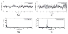
도 4는 본 발명에 일 실시예에 따른 다채널 오목 아치형 건식 뇌파 전극의 성능을 설명하기 위한 도면이다.4 is a view for explaining the performance of a multi-channel concave arcuate dry EEG electrode according to an embodiment of the present invention.
도 4를 참조하면, 도 4(a)는 사용자가 눈을 뜨고 있을 경우, 후두엽에서 측정된 뇌파신호이고, 도4(b)는 사용자가 눈을 감고 있을 경우, 같은 부위에서 측정된 뇌파신호이다. 일반적으로 사람이 눈을 감고 있으면 두엽에서 8 내지 12 Hz의 알파파가 발생하는데, 본 발명에 따른 다채널 오목 아치형 건식 뇌파 전극(1)으로 알파파가 관찰되는 것을 확인할 수 있다.
4 (a) is an EEG signal measured at the occipital lobe when the user is blinking, and Fig. 4 (b) is an EEG signal measured at the same site when the user closes his or her eyes . Generally, when a person closes his or her eyes, an alpha wave of 8 to 12 Hz occurs in the two lobes, and it can be confirmed that the alpha wave is observed with the multi-channel concave arcuate
또한 도 4(c)는 각각의 두 신호의 주파수 분석결과를 도시한 그래프이고, 도 4(d)는 눈을 감았을 경우, 알파파의 피크 파워(peak power)를 관찰할 수 있다.
FIG. 4 (c) is a graph showing the frequency analysis results of the two signals, and FIG. 4 (d) shows the peak power of the alpha waves when the eyes are closed.
이상에서 본 발명의 바람직한 실시예에 대해 도시하고 설명하였으나, 본 발명은 상술한 특정의 바람직한 실시예에 한정되지 아니하며, 청구범위에서 청구하는 본 발명의 요지를 벗어남이 없이 당해 발명이 속하는 기술분야에서 통상의 지식을 가진 자라면 누구든지 다양한 변형 실시가 가능한 것은 물론이고, 그와 같은 변경은 청구범위 기재의 범위 내에 있게 된다.
While the present invention has been particularly shown and described with reference to exemplary embodiments thereof, it is clearly understood that the same is by way of illustration and example only and is not to be taken by way of limitation in the embodiment in which said invention is directed. It will be understood by those skilled in the art that various changes in form and detail may be made therein without departing from the scope of the appended claims.
1: 다채널 오목 아치형 건식 뇌파 전극1: Multi channel concave arched type EEG electrode
Claims (3)
상기 제1 전극을 지지하고, 적어도 하나의 관통구가 형성되며, 하부에 초단회로가 부착되는 제2 전극을 포함하는 두상 곡률을 반영한 다채널 오목 아치형 건식 뇌파 전극.
Five first electrodes formed in a concave-arch shape and spaced apart at predetermined intervals; And
Channel concave arcuate dry EEG electrode that reflects the curvature of the head of the brain including the second electrode supporting the first electrode and having at least one through hole and a first circuit attached to the lower portion.
상기 제1 전극은,
사람 두상의 굴곡을 기초로 상기 오목 아치형상을 형성하는 것을 특징으로 하는 두상 곡률을 반영한 다채널 오목 아치형 건식 뇌파 전극.
The method according to claim 1,
Wherein the first electrode comprises:
Wherein the concave arch shape is formed on the basis of the curvature of the human head.
상기 제1 전극은,
머리카락의 양에 따라 높이 조절을 하는 것을 특징으로 하는 두상 곡률을 반영한 다채널 오목 아치형 건식 뇌파 전극.
The method according to claim 1,
Wherein the first electrode comprises:
A multi-channel concave arcuate dry EEG electrode reflecting the curvature of head, characterized by height adjustment according to the amount of hair.
Priority Applications (1)
| Application Number | Priority Date | Filing Date | Title |
|---|---|---|---|
| KR1020150070451A KR101748133B1 (en) | 2015-05-20 | 2015-05-20 | Head curvature reflected, reversed curve arch shape dry electrodes for multichannel EEG |
Applications Claiming Priority (1)
| Application Number | Priority Date | Filing Date | Title |
|---|---|---|---|
| KR1020150070451A KR101748133B1 (en) | 2015-05-20 | 2015-05-20 | Head curvature reflected, reversed curve arch shape dry electrodes for multichannel EEG |
Publications (2)
| Publication Number | Publication Date |
|---|---|
| KR20160137726A true KR20160137726A (en) | 2016-12-01 |
| KR101748133B1 KR101748133B1 (en) | 2017-06-19 |
Family
ID=57577156
Family Applications (1)
| Application Number | Title | Priority Date | Filing Date |
|---|---|---|---|
| KR1020150070451A Active KR101748133B1 (en) | 2015-05-20 | 2015-05-20 | Head curvature reflected, reversed curve arch shape dry electrodes for multichannel EEG |
Country Status (1)
| Country | Link |
|---|---|
| KR (1) | KR101748133B1 (en) |
Family Cites Families (3)
| Publication number | Priority date | Publication date | Assignee | Title |
|---|---|---|---|---|
| JP3626176B1 (en) * | 2004-09-29 | 2005-03-02 | 晶朗 木村 | Electroencephalogram detection electrode and headset type electroencephalogram measurement apparatus |
| JP2010279452A (en) | 2009-06-03 | 2010-12-16 | Dejitekkusu Kenkyusho:Kk | Bioelectrode for measuring brain wave |
| JP5589593B2 (en) | 2009-06-29 | 2014-09-17 | ソニー株式会社 | Biological signal measuring device |
-
2015
- 2015-05-20 KR KR1020150070451A patent/KR101748133B1/en active Active
Also Published As
| Publication number | Publication date |
|---|---|
| KR101748133B1 (en) | 2017-06-19 |
Similar Documents
| Publication | Publication Date | Title |
|---|---|---|
| CN102458242B (en) | Bio-signal measurement equipment | |
| JP7033614B2 (en) | Measurement of electrical activity | |
| Heslenfeld | Visual mismatch negativity | |
| CN102802516B (en) | Bio-signal measurement equipment | |
| CN101933804B (en) | Mountable unit for biological signal measurement and biological signal measuring method | |
| RU2563433C2 (en) | Device for positioning electrodes on user's head skin | |
| Jiang et al. | Using skin sympathetic nerve activity to estimate stellate ganglion nerve activity in dogs | |
| Cheour et al. | Brain dysfunction in neonates with cleft palate revealed by the mismatch negativity | |
| EP3415081B1 (en) | Electrode, wearable assembly and system | |
| US20100030096A1 (en) | Method of acquiring a physiological response | |
| Greischar et al. | Effects of electrode density and electrolyte spreading in dense array electroencephalographic recording | |
| Dzulkarnain et al. | Effects of different electrode configurations on the narrow band level-specific CE-Chirp and tone-burst auditory brainstem response at multiple intensity levels and frequencies in subjects with normal hearing | |
| Ertl et al. | On the impact of examiners on latencies and amplitudes in cervical and ocular vestibular-evoked myogenic potentials evaluated over a large sample (N= 1,038) | |
| Galbraith et al. | Brainstem frequency-following response recorded from one vertical and three horizontal electrode derivations | |
| KR101748133B1 (en) | Head curvature reflected, reversed curve arch shape dry electrodes for multichannel EEG | |
| JP2007508100A (en) | Multi electrode | |
| JP2018503481A (en) | Headset for acquiring biosignals | |
| Krusienski et al. | Harmonic coupling of steady-state visual evoked potentials | |
| JP5592664B2 (en) | Comfort determination device | |
| Clinard et al. | Inter-trial coherence as a measure of synchrony in cervical vestibular evoked myogenic potentials | |
| WO2011141426A1 (en) | Needle device for detecting biosignals through the skin | |
| Yildiz et al. | Sympathetic skin responses of the face and neck evoked by electrical stimulation | |
| JP2007159644A (en) | holder | |
| Koiwa et al. | Sound localization difficulty affects early and late processing of auditory spatial information: Investigation using the dipole tracing method | |
| Greenwald et al. | Neuroelectric correlates of hemispheric asymmetry: spectral discrimination and stimulus competition |
Legal Events
| Date | Code | Title | Description |
|---|---|---|---|
| PA0109 | Patent application |
St.27 status event code: A-0-1-A10-A12-nap-PA0109 |
|
| A201 | Request for examination | ||
| PA0201 | Request for examination |
St.27 status event code: A-1-2-D10-D11-exm-PA0201 |
|
| PG1501 | Laying open of application |
St.27 status event code: A-1-1-Q10-Q12-nap-PG1501 |
|
| E902 | Notification of reason for refusal | ||
| PE0902 | Notice of grounds for rejection |
St.27 status event code: A-1-2-D10-D21-exm-PE0902 |
|
| P11-X000 | Amendment of application requested |
St.27 status event code: A-2-2-P10-P11-nap-X000 |
|
| P13-X000 | Application amended |
St.27 status event code: A-2-2-P10-P13-nap-X000 |
|
| E701 | Decision to grant or registration of patent right | ||
| PE0701 | Decision of registration |
St.27 status event code: A-1-2-D10-D22-exm-PE0701 |
|
| GRNT | Written decision to grant | ||
| PR0701 | Registration of establishment |
St.27 status event code: A-2-4-F10-F11-exm-PR0701 |
|
| PR1002 | Payment of registration fee |
St.27 status event code: A-2-2-U10-U11-oth-PR1002 Fee payment year number: 1 |
|
| PG1601 | Publication of registration |
St.27 status event code: A-4-4-Q10-Q13-nap-PG1601 |
|
| P22-X000 | Classification modified |
St.27 status event code: A-4-4-P10-P22-nap-X000 |
|
| R18-X000 | Changes to party contact information recorded |
St.27 status event code: A-5-5-R10-R18-oth-X000 |
|
| R18-X000 | Changes to party contact information recorded |
St.27 status event code: A-5-5-R10-R18-oth-X000 |
|
| PN2301 | Change of applicant |
St.27 status event code: A-5-5-R10-R13-asn-PN2301 St.27 status event code: A-5-5-R10-R11-asn-PN2301 |
|
| PR1001 | Payment of annual fee |
St.27 status event code: A-4-4-U10-U11-oth-PR1001 Fee payment year number: 4 |
|
| PN2301 | Change of applicant |
St.27 status event code: A-5-5-R10-R13-asn-PN2301 St.27 status event code: A-5-5-R10-R11-asn-PN2301 |
|
| P22-X000 | Classification modified |
St.27 status event code: A-4-4-P10-P22-nap-X000 |
|
| P22-X000 | Classification modified |
St.27 status event code: A-4-4-P10-P22-nap-X000 |
|
| PR1001 | Payment of annual fee |
St.27 status event code: A-4-4-U10-U11-oth-PR1001 Fee payment year number: 5 |
|
| R18-X000 | Changes to party contact information recorded |
St.27 status event code: A-5-5-R10-R18-oth-X000 |
|
| R18-X000 | Changes to party contact information recorded |
St.27 status event code: A-5-5-R10-R18-oth-X000 |
|
| PR1001 | Payment of annual fee |
St.27 status event code: A-4-4-U10-U11-oth-PR1001 Fee payment year number: 6 |
|
| R18-X000 | Changes to party contact information recorded |
St.27 status event code: A-5-5-R10-R18-oth-X000 |
|
| R18-X000 | Changes to party contact information recorded |
St.27 status event code: A-5-5-R10-R18-oth-X000 |
|
| PR1001 | Payment of annual fee |
St.27 status event code: A-4-4-U10-U11-oth-PR1001 Fee payment year number: 7 |
|
| PR1001 | Payment of annual fee |
St.27 status event code: A-4-4-U10-U11-oth-PR1001 Fee payment year number: 8 |
|
| R18-X000 | Changes to party contact information recorded |
St.27 status event code: A-5-5-R10-R18-oth-X000 |
|
| R18-X000 | Changes to party contact information recorded |
St.27 status event code: A-5-5-R10-R18-oth-X000 |
|
| R18 | Changes to party contact information recorded |
Free format text: ST27 STATUS EVENT CODE: A-5-5-R10-R18-OTH-X000 (AS PROVIDED BY THE NATIONAL OFFICE) |
|
| R18-X000 | Changes to party contact information recorded |
St.27 status event code: A-5-5-R10-R18-oth-X000 |