KR20160136959A - a pump cooling performance is improved - Google Patents
a pump cooling performance is improved Download PDFInfo
- Publication number
- KR20160136959A KR20160136959A KR1020150071263A KR20150071263A KR20160136959A KR 20160136959 A KR20160136959 A KR 20160136959A KR 1020150071263 A KR1020150071263 A KR 1020150071263A KR 20150071263 A KR20150071263 A KR 20150071263A KR 20160136959 A KR20160136959 A KR 20160136959A
- Authority
- KR
- South Korea
- Prior art keywords
- fluid
- water jacket
- cooling
- casing
- cooling adapter
- Prior art date
Links
Images


Classifications
-
- F—MECHANICAL ENGINEERING; LIGHTING; HEATING; WEAPONS; BLASTING
- F04—POSITIVE - DISPLACEMENT MACHINES FOR LIQUIDS; PUMPS FOR LIQUIDS OR ELASTIC FLUIDS
- F04D—NON-POSITIVE-DISPLACEMENT PUMPS
- F04D29/00—Details, component parts, or accessories
- F04D29/58—Cooling; Heating; Diminishing heat transfer
- F04D29/5806—Cooling the drive system
-
- H—ELECTRICITY
- H02—GENERATION; CONVERSION OR DISTRIBUTION OF ELECTRIC POWER
- H02K—DYNAMO-ELECTRIC MACHINES
- H02K9/00—Arrangements for cooling or ventilating
- H02K9/19—Arrangements for cooling or ventilating for machines with closed casing and closed-circuit cooling using a liquid cooling medium, e.g. oil
Abstract
The present invention relates to a pump for sucking and discharging a fluid. The pump with improved cooling performance according to an embodiment of the present invention includes a casing having a suction port and a discharge port, an impeller that rotates inside the casing to generate a suction force and a ground output, and a driving motor that rotates the impeller, An improved pump comprising: a water jacket for cooling the drive motor by a fluid surrounding and surrounding a periphery of the drive motor; a low pressure part for sucking fluid from the casing; A fluid discharge line through which the fluid introduced into the water jacket by connecting the water jacket to a high pressure portion through which the fluid is discharged from the casing is discharged to the casing; Circulating the fluid introduced into the jacket through the inside of the jacket jacket, And a cooling adapter for guiding the movement of the fluid to be discharged to the discharge line. Therefore, the cooling resistance can be minimized by the cooling adapter to improve the cooling performance.
Description
The present invention relates to a pump for sucking and discharging a fluid.
Generally, a pump is a device for sucking and discharging a fluid. The pump includes an impeller rotating by a driving motor and a driving motor, and a casing surrounding the impeller to form an inlet and an outlet.
On the other hand, the performance of the pump is influenced by the drive motor that rotates the impeller. Since the drive motor rotates continuously, it is easily heated, the rotor is expanded and burned due to the heating of the drive motor, There was a problem.
In order to solve this problem, there has been disclosed a "submersible pump with a water channel" disclosed in Korean Patent Laid-Open Publication No. 10-2002-0094756 (published Dec. 18, 2002).
A conventional submerged pump having a water channel includes a main coil housing having a coil wound around a coil forming a magnetic field by a power source and a drive shaft rotatably coupled to the center of the coil assembly by a bearing; An impeller coupled to one end of the shaft; The stand housing includes an inlet and an outlet for sucking and discharging water during rotation of the impeller so as not to interfere with the rotation of the impeller. The stand housing is coupled to the main housing so as to be spaced apart from the main housing. A cover is attached to form a water channel between the main housing and the cover and a connection passage is formed to be connected to a discharge port of the stand housing through which the impeller is rotated so as to be connected to the water channel, A discharge hole is formed in the main housing.
A conventional submerged pump having such a configuration has a water channel formed between the main housing and the cover so that the fluid is sucked by the rotational force of the impeller to pass through the water channel so that the underwater pump is water- .
However, the conventional submersible pump is not directly connected to the main housing and the cover because there is no structure for guiding the fluid between the main housing and the cover, , There is a problem that the movement of the fluid is uneven due to the mixing of air and the cooling performance is lowered.
SUMMARY OF THE INVENTION The present invention has been devised to solve the above-mentioned problems, and an object of the present invention is to provide a water jacket capable of improving the cooling performance by smoothly moving the fluid inside the water jacket, And to improve the cooling performance by delaying the discharge of the fluid so as to improve the cooling performance.
According to an aspect of the present invention, there is provided a pump having improved cooling performance, comprising: a casing having a suction port and a discharge port; an impeller which rotates inside the casing to generate a suction force and a ground output; 1. A pump having improved cooling performance including a motor, comprising: a water jacket for cooling the drive motor by a fluid surrounding and surrounding the drive motor; a water jacket for connecting the water jacket to a low- A fluid discharge line connecting the water jacket to the fluid jacket and discharging the fluid introduced into the water jacket to the casing; The fluid introduced into the water jacket through the fluid supply line is supplied to the jacket And a cooling adapter circulating the inside of the fluid discharge line to guide the movement of the fluid to be discharged to the fluid discharge line.
The water jacket may include an exhaust valve for discharging the air contained in the fluid flowing through the fluid supply line to the outside.
The cooling adapter may partition the interior of the water jacket such that fluid flowing through the lower portion of the fluid supply line passes through the upper portion of the water jacket and is discharged to a lower portion of the fluid supply line.
The cooling adapter may be configured to increase the pressure of the fluid flowing into the water jacket through the fluid supply line and to narrow the area from the lower part to the upper part so as to be discharged to the fluid discharge line.
The fluid flowing into the interior of the water jacket through the fluid supply line installed on the inner circumferential surface of the cooling adapter or the surface of the water jacket facing the inner circumferential surface of the cooling adapter is circulated in a spiral form inside the cooling adapter And may include a guide collar.
The cooling adapter is installed in the water jacket to be rotatable in the water jacket by the guide collar. The cooling adapter and the water jacket are rotated by the rotation of the water jacket so that the fluid flowing into the water jacket is sufficiently heat- And a delayed discharge unit for delaying the discharge of the fluid introduced into the water jacket by being opened or closed.
Wherein the delayed discharge portion comprises a plurality of first communication holes formed radially apart from each other in the water jacket and a second communication hole formed in the water jacket and communicated with the first communication hole according to rotation of the water jacket, . ≪ / RTI >
According to the present invention, a cooling adapter for guiding the movement of the fluid is provided inside the water jacket to guide the movement of the fluid, thereby smoothly moving the fluid inside the water jacket, thereby improving the cooling performance of the drive motor .
Further, an exhaust valve is provided in the water jacket to prevent abnormal flow caused by entrained air.
In addition, the cooling adapter is rotatably installed by the fluid sucked in the water jacket to generate a suction force and a ground output, so that the fluid can be sucked and discharged smoothly inside the water jacket.
In addition, a delayed discharge is provided between the cooling adapter and the water jacket to delay the discharge of the fluid, thereby sufficiently securing the time for the drive motor to perform heat exchange with the fluid, thereby improving the cooling performance.
1 is a view showing a state in which a pump having improved cooling performance according to an embodiment of the present invention is installed in a water storage tank.
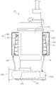
2 is a side view schematically showing a pump with improved cooling performance according to an embodiment of the present invention.
FIG. 3 is a partially cut-away perspective view of a cooling adapter of a pump with improved cooling performance according to an embodiment of the present invention.
FIG. 4 is a plan view showing a cooling adapter of a pump with improved cooling performance according to an embodiment of the present invention, wherein (a) is a state in which the delayed discharge portion is hermetically closed according to the rotation angle of the cooling adapter, (b) And the delayed discharge portion is opened according to the angle.
5 is a side view showing a state in which the present invention is applied to a multi-stage pump, the pump having improved cooling performance according to an embodiment of the present invention.
Hereinafter, embodiments of the present invention will be described with reference to the accompanying drawings.
The
As shown in FIGS. 1 and 2, the
This
Meanwhile, the
The
The driving
On the other hand, the driving
When the driving
The
The
The
The
Meanwhile, the
The
In addition, the
The
The
Here, when air is mixed in the fluid supplied to the
Therefore, the
The
The
The
The
The
On the other hand, the
As shown in FIG. 3, the
The
The cooling
Further, the cooling
This
The
In this case, when the
Meanwhile, the cooling
The cooling
At this time, the cooling
Meanwhile, the cooling
The delayed
The delayed
4 (a) and 4 (b), a plurality of first communication holes 143 are formed in the upper end portion of the cooling
The operation and effect between the above-described respective constitutions will be described.
The
A
At this time, the
A cooling
The cooling
A
The
When the
The fluid flowing in a spiral shape on the
The fluid discharged to the outside of the cooling
The fluid flowing into the cooling
Since the fluid flowing into the cooling
In addition, when the air contained in the fluid is collected at the upper portion of the
Accordingly, the
A cooling
The cooling
While the present invention has been described with reference to exemplary embodiments, it is to be understood that the invention is not limited to the disclosed exemplary embodiments, but, on the contrary, And all changes and modifications to the scope of the invention.
100: pump with improved cooling performance 110: drive motor
120: impeller 130: casing
131: Fluid inlet 133: Fluid outlet
140: Water jacket 141: Exhaust valve
143: first communication hole 150: cooling adapter
151: Flap 153: Second communication hole
160: delayed discharge unit 170: fluid supply line
180: fluid discharge line 200: column pipe
Claims (7)
A water jacket that surrounds the driving motor and cools the driving motor by a fluid accommodated in the water jacket,
A fluid supply line for connecting the water jacket to a low pressure portion where fluid is sucked from the casing and supplying the fluid to the water jacket,
A fluid discharge line for connecting the water jacket to a high-pressure portion through which fluid is discharged from the casing and discharging the fluid introduced into the water jacket to the casing;
And a cooling adapter for circulating the fluid introduced into the water jacket through the fluid supply line to guide the movement of the fluid to be discharged to the fluid discharge line.
The water jacket
And an exhaust valve for discharging the air contained in the fluid flowing through the fluid supply line to the outside.
The cooling adapter
Wherein a portion of the water jacket is divided so that a fluid flowing through a lower portion of the fluid supply line passes through an upper portion of the water jacket and is discharged to a lower portion of the fluid supply line.
The cooling adapter
Wherein the water jacket is configured to increase the pressure of the fluid flowing into the water jacket through the fluid supply line so that the area becomes narrower from the bottom to the top so as to be discharged to the fluid discharge line.
The fluid flowing into the interior of the water jacket through the fluid supply line installed on the inner circumferential surface of the cooling adapter or the surface of the water jacket facing the inner circumferential surface of the cooling adapter is circulated in a spiral form inside the cooling adapter Wherein the pump comprises a guide collar.
The cooling adapter
The water jacket being rotatably installed inside the water jacket by the guide collar,
And a delayed discharge unit for delaying the discharge of the fluid introduced into the water jacket by being opened or closed by the rotation so that the fluid introduced into the water jacket sufficiently flows into the cooling jacket and the water jacket after being heat- Wherein the cooling performance is improved.
The delay-
A plurality of first communication holes formed radially apart from each other of the water jacket, and
And a second communication hole formed in the water jacket and communicating with or sealing the first communication hole according to rotation of the water jacket.
Priority Applications (1)
| Application Number | Priority Date | Filing Date | Title |
|---|---|---|---|
| KR1020150071263A KR20160136959A (en) | 2015-05-21 | 2015-05-21 | a pump cooling performance is improved |
Applications Claiming Priority (1)
| Application Number | Priority Date | Filing Date | Title |
|---|---|---|---|
| KR1020150071263A KR20160136959A (en) | 2015-05-21 | 2015-05-21 | a pump cooling performance is improved |
Related Child Applications (1)
| Application Number | Title | Priority Date | Filing Date |
|---|---|---|---|
| KR1020170045464A Division KR101756979B1 (en) | 2017-04-07 | 2017-04-07 | a pump cooling performance is improved |
Publications (1)
| Publication Number | Publication Date |
|---|---|
| KR20160136959A true KR20160136959A (en) | 2016-11-30 |
Family
ID=57707263
Family Applications (1)
| Application Number | Title | Priority Date | Filing Date |
|---|---|---|---|
| KR1020150071263A KR20160136959A (en) | 2015-05-21 | 2015-05-21 | a pump cooling performance is improved |
Country Status (1)
| Country | Link |
|---|---|
| KR (1) | KR20160136959A (en) |
Cited By (5)
| Publication number | Priority date | Publication date | Assignee | Title |
|---|---|---|---|---|
| CN109812422A (en) * | 2019-01-11 | 2019-05-28 | 江苏泰丰泵业有限公司 | A kind of bedroom water supply pump |
| KR102078203B1 (en) * | 2019-01-15 | 2020-02-19 | 세한산업기계 주식회사 | Amphibious vertical multi-stage pump |
| KR20210001390U (en) * | 2019-12-12 | 2021-06-22 | 세한산업기계 주식회사 | Amphibious horizontal pump |
| CN113700655A (en) * | 2020-05-21 | 2021-11-26 | 上海凯士比泵有限公司 | Inside and outside self-loopa's cooling system of converter and motor integrated device |
| CN114396111A (en) * | 2021-12-28 | 2022-04-26 | 威乐(中国)水泵系统有限公司 | Sewage lifting device |
-
2015
- 2015-05-21 KR KR1020150071263A patent/KR20160136959A/en active Application Filing
Cited By (7)
| Publication number | Priority date | Publication date | Assignee | Title |
|---|---|---|---|---|
| CN109812422A (en) * | 2019-01-11 | 2019-05-28 | 江苏泰丰泵业有限公司 | A kind of bedroom water supply pump |
| CN109812422B (en) * | 2019-01-11 | 2020-09-04 | 江苏泰丰泵业有限公司 | Horizontal cold water pump |
| KR102078203B1 (en) * | 2019-01-15 | 2020-02-19 | 세한산업기계 주식회사 | Amphibious vertical multi-stage pump |
| KR20210001390U (en) * | 2019-12-12 | 2021-06-22 | 세한산업기계 주식회사 | Amphibious horizontal pump |
| CN113700655A (en) * | 2020-05-21 | 2021-11-26 | 上海凯士比泵有限公司 | Inside and outside self-loopa's cooling system of converter and motor integrated device |
| CN114396111A (en) * | 2021-12-28 | 2022-04-26 | 威乐(中国)水泵系统有限公司 | Sewage lifting device |
| CN114396111B (en) * | 2021-12-28 | 2024-02-06 | 威乐(中国)水泵系统有限公司 | Sewage lifting device |
Similar Documents
| Publication | Publication Date | Title |
|---|---|---|
| KR20160136959A (en) | a pump cooling performance is improved | |
| KR101042028B1 (en) | Motor pump | |
| JP4872456B2 (en) | Pump and liquid supply device | |
| JP6057566B2 (en) | Fluid pump | |
| JP2015537160A (en) | Cooling configuration of liquid pump | |
| JP2000110768A (en) | Closed loop compulsory cooling system for submarine pump motor | |
| KR101784909B1 (en) | Apparatus for cooling submerged motor pump | |
| WO2016075636A1 (en) | Electric pump with closed loop cooling system | |
| KR101756979B1 (en) | a pump cooling performance is improved | |
| AU2016228251B2 (en) | Pump and method for changing the pumping capacity of a pump | |
| US9388811B2 (en) | Micropump structure | |
| KR101826600B1 (en) | Pump for Circulating Water | |
| CN108138801B (en) | Boiler pump | |
| KR101787706B1 (en) | Unified Oil and water pump | |
| CN219366406U (en) | Centrifugal fan with heat dissipation cooling function | |
| EP3147509B1 (en) | Multistage centrifugal pump with a cooled frequency converter placed between the pump and the motor | |
| RU2641328C1 (en) | Centrifugal pumping unit | |
| JP6234257B2 (en) | Pump and water resistant motor | |
| KR20170136825A (en) | Compressor and compressor system | |
| KR101827295B1 (en) | Pump for Circulating Hot Water | |
| JP6476011B2 (en) | Pump device | |
| KR100562833B1 (en) | Both direction circular Pump | |
| KR200477242Y1 (en) | a underwater pump | |
| KR102188203B1 (en) | Pump | |
| KR102188200B1 (en) | Pump |
Legal Events
| Date | Code | Title | Description |
|---|---|---|---|
| A201 | Request for examination | ||
| E902 | Notification of reason for refusal | ||
| E601 | Decision to refuse application | ||
| A107 | Divisional application of patent |