KR20160132055A - Prioritized cell identification and measurement method - Google Patents
Prioritized cell identification and measurement method Download PDFInfo
- Publication number
- KR20160132055A KR20160132055A KR1020167027714A KR20167027714A KR20160132055A KR 20160132055 A KR20160132055 A KR 20160132055A KR 1020167027714 A KR1020167027714 A KR 1020167027714A KR 20167027714 A KR20167027714 A KR 20167027714A KR 20160132055 A KR20160132055 A KR 20160132055A
- Authority
- KR
- South Korea
- Prior art keywords
- group
- storage medium
- computer readable
- readable storage
- frequency
- Prior art date
Links
- 238000000691 measurement method Methods 0.000 title description 2
- 238000005259 measurement Methods 0.000 claims abstract description 109
- 238000000034 method Methods 0.000 claims abstract description 65
- 238000005516 engineering process Methods 0.000 claims description 9
- 238000004891 communication Methods 0.000 claims description 6
- 230000007774 longterm Effects 0.000 claims description 4
- 229910052709 silver Inorganic materials 0.000 claims description 4
- 239000004332 silver Substances 0.000 claims description 4
- 230000000737 periodic effect Effects 0.000 claims 2
- 230000008859 change Effects 0.000 abstract description 9
- 238000013461 design Methods 0.000 abstract description 6
- 230000011664 signaling Effects 0.000 abstract description 5
- 238000013468 resource allocation Methods 0.000 description 20
- 230000005540 biological transmission Effects 0.000 description 18
- 101100411667 Arabidopsis thaliana RAN4 gene Proteins 0.000 description 14
- 238000010586 diagram Methods 0.000 description 10
- XEEYBQQBJWHFJM-UHFFFAOYSA-N Iron Chemical compound [Fe] XEEYBQQBJWHFJM-UHFFFAOYSA-N 0.000 description 9
- 238000012544 monitoring process Methods 0.000 description 6
- 241000700159 Rattus Species 0.000 description 5
- 239000000969 carrier Substances 0.000 description 5
- 238000012545 processing Methods 0.000 description 4
- 230000001413 cellular effect Effects 0.000 description 3
- 238000001514 detection method Methods 0.000 description 3
- 238000010295 mobile communication Methods 0.000 description 3
- 238000012360 testing method Methods 0.000 description 3
- 101150014328 RAN2 gene Proteins 0.000 description 2
- 230000001934 delay Effects 0.000 description 2
- 238000012986 modification Methods 0.000 description 2
- 230000004048 modification Effects 0.000 description 2
- 230000008054 signal transmission Effects 0.000 description 2
- 101150074586 RAN3 gene Proteins 0.000 description 1
- 230000002776 aggregation Effects 0.000 description 1
- 238000004220 aggregation Methods 0.000 description 1
- 238000012512 characterization method Methods 0.000 description 1
- 238000001914 filtration Methods 0.000 description 1
- 230000006870 function Effects 0.000 description 1
- 239000011159 matrix material Substances 0.000 description 1
- 230000008520 organization Effects 0.000 description 1
- 230000008569 process Effects 0.000 description 1
- 230000003595 spectral effect Effects 0.000 description 1
Images


Classifications
-
- H—ELECTRICITY
- H04—ELECTRIC COMMUNICATION TECHNIQUE
- H04W—WIRELESS COMMUNICATION NETWORKS
- H04W24/00—Supervisory, monitoring or testing arrangements
- H04W24/10—Scheduling measurement reports ; Arrangements for measurement reports
-
- H—ELECTRICITY
- H04—ELECTRIC COMMUNICATION TECHNIQUE
- H04L—TRANSMISSION OF DIGITAL INFORMATION, e.g. TELEGRAPHIC COMMUNICATION
- H04L5/00—Arrangements affording multiple use of the transmission path
- H04L5/003—Arrangements for allocating sub-channels of the transmission path
- H04L5/0048—Allocation of pilot signals, i.e. of signals known to the receiver
-
- H—ELECTRICITY
- H04—ELECTRIC COMMUNICATION TECHNIQUE
- H04W—WIRELESS COMMUNICATION NETWORKS
- H04W24/00—Supervisory, monitoring or testing arrangements
- H04W24/02—Arrangements for optimising operational condition
-
- H—ELECTRICITY
- H04—ELECTRIC COMMUNICATION TECHNIQUE
- H04W—WIRELESS COMMUNICATION NETWORKS
- H04W24/00—Supervisory, monitoring or testing arrangements
- H04W24/08—Testing, supervising or monitoring using real traffic
-
- H—ELECTRICITY
- H04—ELECTRIC COMMUNICATION TECHNIQUE
- H04W—WIRELESS COMMUNICATION NETWORKS
- H04W72/00—Local resource management
- H04W72/04—Wireless resource allocation
- H04W72/044—Wireless resource allocation based on the type of the allocated resource
- H04W72/0453—Resources in frequency domain, e.g. a carrier in FDMA
Abstract
우선순위화된 셀 식별 및 측정이 개시된다. 방법은, 사용자 장비에 의해 모니터링되고 측정되는 주파수 계층을 정규의 성능 그룹 및 감소된 성능 그룹으로 분류한다. 몇몇 상이한 실시예가 설명된다. 적절한 경우, 대응하는 시그널링 설계가 또한 제시된다. 사용자 장비는 이러한 실시예 중 하나 또는 몇몇을 채택할 수 있고, 동작 조건에 기초하여 준-정적 방식으로 구성을 변경할 수 있다.Prioritized cell identification and measurement is initiated. The method classifies the frequency layers that are monitored and measured by the user equipment into regular performance groups and reduced performance groups. Several different embodiments are described. If appropriate, a corresponding signaling design is also presented. The user equipment may employ one or several of these embodiments and may change the configuration in a quasi-static manner based on operating conditions.

Description
본 출원은 2014년 5월 8일에 출원된 미국 특허 가출원 제61/990,647호의 계속출원이다.This application is a continuation-in-part of U.S. Provisional Patent Application No. 61 / 990,647, filed May 8, 2014.
본 출원은, 롱 텀 에볼루션(LTE) 표준 하에서 동작하는 사용자 장비에 의해 취해진 측정과 관련된다.The present application relates to measurements taken by user equipment operating under the Long Term Evolution (LTE) standard.
진화된 패킷 코어(EPC)는 어드밴스드 모바일 통신 시스템의 코어 네트워크이다. EPC는 상이한 무선 액세스 기술(RAT)이 통합된 방식으로 동작하도록 허용한다. 이러한 무선 액세스 기술은, 1세대 무선 로컬 영역 네트워크(LAN), 2세대(2G) 시스템, 예를 들어, 모바일 통신용 범용 시스템, 즉 GSM, 3세대(3G), 예를 들어, UMTS(universal mobile telecommunication system) 및 4세대(4G), 예를 들어, 롱 텀 에볼루션(LTE)을 포함한다. LTE는 3세대 파트너쉽 프로젝트, 이하 "3GPP 규격"에 의해 공표된 규격이다.Evolved Packet Core (EPC) is the core network of an advanced mobile communication system. The EPC allows different Radio Access Technologies (RAT) to operate in an integrated manner. This radio access technology may be used in a first generation wireless local area network (LAN), a second generation (2G) system, for example a general purpose system for mobile communications, GSM, third generation (3G), e.g. universal mobile telecommunication system and a fourth generation (4G), e.g., Long Term Evolution (LTE). LTE is a third generation partnership project, a standard published by the "3GPP standard ".
무선 모바일 통신 기술은 노드(예를 들어, 송신 스테이션 또는 트랜시버 노드)와 무선 디바이스(예를 들어, 모바일 디바이스) 사이에서 데이터를 송신하기 위해 다양한 표준 및 프로토콜을 이용한다. 일부 무선 디바이스는, 다운링크(DL) 송신에서는 직교 주파수 분할 다중 액세스(OFDMA)를 그리고 업링크(UL) 송신에서는 싱글 캐리어 주파수 분할 다중 액세스(SC-FDMA)를 이용하여 통신한다. 신호 송신을 위해 직교 주파수 분할 멀티플렉싱(OFDM)을 이용하는 표준 및 프로토콜은 LTE(3GPP), 통상적으로 WiMAX(worldwide interoperability for microwave access)로서 산업 그룹에 공지된 IEEE(Institute of Electrical and Electronics Engineers) 802.16 표준(예를 들어, 802.16e, 802.16m), 및 통상적으로 WiFi로 산업 그룹에 공지된 IEEE 802.11 표준을 포함한다.Wireless mobile communication technologies employ various standards and protocols for transmitting data between a node (e.g., a transmitting station or a transceiver node) and a wireless device (e.g., a mobile device). Some wireless devices communicate using Orthogonal Frequency Division Multiple Access (OFDMA) in downlink (DL) transmission and Single Carrier Frequency Division Multiple Access (SC-FDMA) in uplink (UL) transmission. Standards and protocols that use Orthogonal Frequency Division Multiplexing (OFDM) for signal transmission include LTE (3GPP), IEEE (Institute of Electrical and Electronics Engineers) 802.16 standard, commonly known as industry interoperability for microwave access (WiMAX) For example, 802.16e, 802.16m), and IEEE 802.11 standards commonly known in the industry as WiFi.
3GPP 무선 액세스 네트워크(RAN) LTE 시스템에서, 노드는 E-UTRAN(evolved universal terrestrial radio access network) NodeB(또한 통상적으로 진화된 NodeB, 향상된 NodeB, eNodeB 또는 eNB로 표기됨) 및 무선 네트워크 제어기(RNC)의 결합일 수 있다. eNB는 사용자 장비(UE)로 공지된 무선 디바이스와 통신한다. DL 송신은 노드(예를 들어, eNB)로부터 무선 디바이스(예를 들어, UE)로의 통신일 수 있고, UL 송신은 무선 디바이스로부터 노드로의 통신일 수 있다.In a 3GPP radio access network (RAN) LTE system, a node includes an evolved universal terrestrial radio access network (E-UTRAN) NodeB (also commonly referred to as an evolved NodeB, an enhanced NodeB, an eNodeB or an eNB) Lt; / RTI > The eNB communicates with a wireless device known as a user equipment (UE). A DL transmission may be a communication from a node (e.g., eNB) to a wireless device (e.g., a UE), and an UL transmission may be from a wireless device to a node.
셀폰과 같은 UE는 다수의 RAT를 지원할 수 있어서 멀티-모드 UE로 공지된다. 멀티-모드 UE에서 한번에 오직 하나의 RAT만이 동작가능하다. 하나의 RAT에 "캠핑" 온되는 것으로 지칭되는 멀티-모드 UE(50)는 오직 그 RAT의 기술만을 활용하고 있다. UE는 하나의 RAT로부터 다른 RAT로 스위칭되어, UE가 캠핑되는 곳을 스위칭할 수 있다. 따라서, 멀티-모드 UE는 LTE에 캠핑 온될 수 있고, 4G RAT로부터 3G RAT로 스위칭될 수 있고, 그 후 UMTS에 캠핑 온된다.A UE, such as a cell phone, can support multiple RATs and is known as a multi-mode UE. Only one RAT is operational at a time in a multi-mode UE. A multi-mode UE 50, referred to as being "camped on " to one RAT, is utilizing only that RAT's technology. The UE may switch from one RAT to another RAT to switch where the UE camps. Thus, the multi-mode UE can camp on LTE, switch from 4G RAT to 3G RAT, and then camp on to UMTS.
캐리어 어그리게이션 하에서, UE는 2개의 상이한 RAT와 동시에 통신할 수 있다. 따라서, UE는 다수의 캐리어 주파수로부터의 무선 자원을 동시에 활용할 수 있다.Under carrier aggregation, the UE can communicate with two different RATs at the same time. Thus, the UE can simultaneously utilize radio resources from a plurality of carrier frequencies.
동종(homogeneous) 네트워크에서, 매크로 노드 또는 매크로 eNB로도 지칭되는 eNB는 셀의 무선 디바이스에 기본적 무선 커버리지를 제공할 수 있다. 셀은, 무선 디바이스가 매크로 eNB와 통신하도록 동작가능한 물리적 구역 또는 영역일 수 있다. 이종(heterogeneous) 네트워크(HetNet)는, 무선 디바이스의 증가된 사용 및 기능으로 인한 매크로 노드 상의 증가된 트래픽 부하를 처리하기 위해 이용될 수 있다. HetNet은 매크로 노드의 커버리지 영역(셀) 내에서 덜 양호하게 계획된 방식으로 또는 심지어 완전히 조정되지 않은 방식으로 배치될 수 있는 저전력 노드(소형-eNB, 마이크로-eNB, 피코-eNB, 펨토-eNB, 또는 홈 eNB(HeNB))의 계층에 의해 오버레이되는 계획된 고전력 매크로 eNB의 계층을 포함할 수 있다. 저전력 노드(LPN)는 일반적으로 "저전력 노드", 소형 노드 또는 소형 셀로 지칭될 수 있다.In a homogeneous network, an eNB, also referred to as a macro node or macro eNB, may provide basic wireless coverage to the cell's wireless device. The cell may be a physical zone or zone that is operable for the wireless device to communicate with the macro eNB. A heterogeneous network (HetNet) can be used to handle the increased traffic load on a macro node due to increased usage and functionality of the wireless device. HetNet is a low power node (small-eNB, micro-eNB, pico-eNB, femto-eNB, or pico-eNB) that can be placed in a less well-planned manner or even in a not fully coordinated manner within the coverage area And a layer of a planned high power macro eNB overlaid by a layer of a home eNB (HeNB). A low power node (LPN) can generally be referred to as a "low power node ", a small node or a small cell.
매크로 노드는 기본적 커버리지에 대해 이용될 수 있다. 저전력 노드는, 커버리지 홀(hole)을 채우기 위해, 매크로 노드의 커버리지 영역들 사이의 경계에서 또는 핫 존(hot zone)에서 용량을 개선하기 위해, 그리고 건물 구조물들이 신호 송신을 방해하는 실내 커버리지를 개선하기 위해 이용될 수 있다. HetNet에서 매크로 노드 및 저전력 노드와 같은 노드들 사이에서 간섭을 감소시키기 위해 셀간 간섭 조정(ICIC) 또는 향상된 ICIC(eICIC)가 이용될 수 있다.Macro nodes can be used for basic coverage. The low power node can be used to fill coverage holes, to improve capacity at the boundary between the coverage areas of the macro nodes or in a hot zone, and to improve indoor coverage where building structures interfere with signal transmission . ≪ / RTI > In HetNet, inter-cell interference coordination (ICIC) or enhanced ICIC (eICIC) may be used to reduce interference between nodes such as macro nodes and low power nodes.
HetNet은 다운링크 또는 업링크 송신을 위해 시분할 듀플렉싱(TDD) 또는 주파수 분할 듀플렉싱(FDD)을 이용할 수 있다. TDD는 다운링크 및 업링크 신호를 분리하기 위한 시분할 멀티플렉싱(TDM)의 적용이다. TDD에서, DL 및 UL 신호는 동일한 캐리어 주파수 상에서 반송될 수 있고, 여기서 DL 신호는 UL 신호와는 상이한 시간 인터벌을 이용한다. 따라서, DL 신호 및 UL 신호는 서로 간섭을 생성하지 않는다. TDM은, DL 또는 UL 신호와 같은 둘 이상의 비트 스트림 또는 신호가 하나의 통신 채널의 서브-채널로서 명백하게 동시에 전송되지만, 상이한 시간 자원들 상에서 물리적으로 송신되는 디지털 멀티플렉싱 타입이다. FDD에서, UL 송신 및 DL 송신은 상이한 주파수 캐리어를 이용하여 동작할 수 있다. FDD에서는, DL 신호가 UL 신호와는 상이한 주파수 캐리어를 이용하기 때문에, 간섭이 회피될 수 있다.HetNet may use Time Division Duplexing (TDD) or Frequency Division Duplexing (FDD) for downlink or uplink transmission. TDD is the application of time division multiplexing (TDM) to separate the downlink and uplink signals. In TDD, DL and UL signals can be carried on the same carrier frequency, where the DL signal uses a different time interval than the UL signal. Therefore, the DL signal and the UL signal do not generate interference with each other. A TDM is a type of digital multiplexing where two or more bitstreams or signals such as DL or UL signals are transmitted concurrently as sub-channels of one communication channel, but are physically transmitted on different time resources. In FDD, UL transmissions and DL transmissions may operate using different frequency carriers. In the FDD, since the DL signal uses a frequency carrier different from the UL signal, interference can be avoided.
시분할 듀플렉싱(TDD)은 한 쌍의 스펙트럼 자원을 요구함이 없이 유연한 배치를 제공한다. 롱 텀 에볼루션(LTE) TDD는 비대칭적인 업링크-다운링크(UL-DL) 할당을 허용한다.Time Division Duplexing (TDD) provides flexible placement without requiring a pair of spectral resources. Long Term Evolution (LTE) TDD allows asymmetric uplink-downlink (UL-DL) allocation.
UE가 무선 이웃에서 동작할 때, 채널 조건은 변한다. 이것은, UE에 의한 이동, UE의 시선에 있는 건물 및 차량의 존재, 및 예를 들어, 이웃 스테이션으로부터의 간섭과 같은 다른 조건들 등에 기인할 수 있다. 채널 상태 정보(CSI)는, 채널 조건에 대한 데이터이고, 무선 통신 동안 UE에 의해 eNB에 제공된다. CSI는 채널 품질 정보(CQI), 프리-코딩 행렬 표시, 랭크 표시 및 무선 채널에 대한 다른 특성 정보를 포함한다.When the UE is operating in a wireless neighbor, the channel conditions change. This may be due to movement by the UE, the presence of buildings and vehicles in the line of sight of the UE, and other conditions such as, for example, interference from neighboring stations. Channel state information (CSI) is data on channel conditions and is provided to the eNB by the UE during wireless communication. The CSI includes channel quality information (CQI), pre-coding matrix representation, rank indication, and other property information for the wireless channel.
3GPP 조직은 LTE 하의 특정 작업에 전용되는 몇몇 동작 그룹을 포함한다. 무선 액세스 네트워크 1(RAN1)은 물리 계층을 정의하는 것을 담당하고; RAN2는 물리 계층의 최상부에서 무선 인터페이스 프로토콜을 다루고; RAN3은 전반적 UTRAN(EUTRAN) 아키텍쳐와 관련되고; RAN4는 UTRAN(EUTRAN)의 RF 준수 양상, RF 송신 및 수신 성능에 관한 단말 장비 및 무선 네트워크에 대한 테스트 규격에 전용되고; RAN5는 무선 인터페이스 준수 테스트 규격, RAN4 규격에 기초한 테스트 규격 및 RAN2와 같은 다른 그룹에 의해 정의되는 시그널링 절차와 관련된다.The 3GPP organization includes several groups of operations dedicated to specific tasks under LTE. The radio access network 1 (RAN1) is responsible for defining the physical layer; RAN2 covers the air interface protocol at the top of the physical layer; RAN3 is associated with the overall UTRAN (EUTRAN) architecture; RAN4 is dedicated to test specifications for terminal equipment and wireless networks on RF compliance aspects of UTRAN (EUTRAN), RF transmission and reception capabilities; RAN5 relates to the air interface compliance test specification, the test specification based on the RAN4 specification, and the signaling procedures defined by other groups such as RAN2.
LTE 규격 하에서, UE는 UE의 서빙 1차 셀(pcell) 뿐만 아니라 UE의 2차 셀(scell)에 대한 주파수(또한 계층, 주파수 계층, 캐리어 또는 대역으로 지칭됨)를 모니터링한다. pcell에 의해 서빙되는 동안 UE는 pcell 주파수 상에서 유지된다. pcell 주파수 계층 및 scell 주파수 계층은 제 1 레이트로 모니터링된다.Under the LTE standard, the UE monitors the frequency (also referred to as layer, frequency layer, carrier, or band) for the UE's secondary cell (scell) as well as the serving primary cell (pcell) of the UE. The UE is maintained on the pcell frequency while being served by pcell. The pcell frequency layer and the scell frequency layer are monitored at a first rate.
추가적으로, UE는 제 2의 더 낮은 레이트로 다른 RAT를 포함하는 다른 주파수를 모니터링하여, 상이한 주파수 대역(RAT간 모니터링의 경우)으로의 핸드오버 또는 상이한 RAT, 예를 들어, USTM(3G) 또는 WiFi(2G)로의 스위칭이 필요하게 되면, UE는 이러한 주파수 계층의 특성을 인식한다.Additionally, the UE can monitor other frequencies, including other RATs, at a second lower rate to provide handover to different frequency bands (for inter-RAT monitoring) or different RATs, e.g., USTM (3G) or WiFi (2G), the UE recognizes the characteristics of this frequency layer.
이전에 LTE 하에서, UE는 8개 이상의 주파수 계층을 모니터링하도록 예상되었다. 최근의 RAN4 변형(RAN4, 릴리스 12) 하에서 모니터링되는 EUTRAN의 주파수 계층의 최소 수는 8개에서 13개로 증가되었다.Previously under LTE, the UE was expected to monitor more than 8 frequency layers. The minimum number of frequency layers of EUTRAN monitored under the recent RAN4 variant (RAN4, Release 12) was increased from 8 to 13.
따라서, RAN4 릴리스 12 요건을 처리하는 셀 식별 및 측정 방법에 대한 요구가 존재한다.Thus, there is a need for a cell identification and measurement method that addresses the RAN4 Release 12 requirement.
본 문헌의 전술된 양상 및 많은 수반되는 이점은, 첨부된 도면과 함께 고려되는 경우 하기 상세한 설명을 참조하여 더 잘 이해되기 때문에 더 쉽게 인식될 것이고, 유사한 참조 부호는, 달리 특정되지 않으면 다양한 도면 전반에 걸쳐 유사한 부분을 지칭한다.
도 1은, 일부 실시예에 따른 우선순위화된 셀 식별 및 측정(PCIM) 방법의 단순화된 블록도이다.
도 2는, 특정 실시예에 따른 무선 네트워크의 단순화된 도면이다.
도 3은, 일부 실시예에 따른 도 1의 PCIM 방법을 구현하기 위한 이종 무선 네트워크의 단순화된 도면이다.
도 4는, 일부 실시예에 따른 도 1의 PCIM 방법에 의해 이용되는 측정 갭 반복 기간의 도면이다.
도 5는, 일부 실시예에 따른 도 1의 PCIM 방법의 제 1 실시예에서 수행되는 동작들을 도시하는 흐름도이다.
도 6은, 일부 실시예에 따른 도 1의 PCIM 방법의 제 2 실시예에서 수행되는 동작들을 도시하는 흐름도이다.
도 7은, 일부 실시예에 따른 도 1의 PCIM 방법의 제 3 실시예에서 수행되는 동작들을 도시하는 흐름도이다.
도 8은, 일부 실시예에 따른 도 1의 PCIM 방법의 제 4 실시예에서 수행되는 동작들을 도시하는 흐름도이다.
도 9는, 일부 실시예에 따른 도 1의 PCIM 방법의 제 5 실시예에서 수행되는 동작들을 도시하는 흐름도이다.
도 10a 및 도 10b는 향상된 노드 B 및 사용자 장비를 특징으로 하는 무선 이웃의 단순화된 시스템 도면이고, 둘 모두는 일부 실시예에 따른 도 1의 PCIM 방법을 구현하고 있다.The foregoing aspects and many of the attendant advantages of this document will become more readily appreciated as the same becomes better understood by reference to the following detailed description when considered in conjunction with the accompanying drawings, Quot; refer to similar parts throughout.
1 is a simplified block diagram of a prioritized cell identification and measurement (PCIM) method according to some embodiments.
2 is a simplified diagram of a wireless network according to a particular embodiment.
Figure 3 is a simplified diagram of a heterogeneous wireless network for implementing the PCIM method of Figure 1 in accordance with some embodiments.
4 is a diagram of a measurement gap repetition period used by the PCIM method of FIG. 1 in accordance with some embodiments.
Figure 5 is a flow chart illustrating operations performed in a first embodiment of the PCIM method of Figure 1 in accordance with some embodiments.
Figure 6 is a flow chart illustrating operations performed in a second embodiment of the PCIM method of Figure 1 in accordance with some embodiments.
Figure 7 is a flow chart illustrating operations performed in a third embodiment of the PCIM method of Figure 1 in accordance with some embodiments.
Figure 8 is a flow chart illustrating operations performed in a fourth embodiment of the PCIM method of Figure 1 in accordance with some embodiments.
Figure 9 is a flow chart illustrating operations performed in a fifth embodiment of the PCIM method of Figure 1 in accordance with some embodiments.
10A and 10B are simplified system diagrams of a wireless neighbor featuring enhanced Node B and user equipment, both of which implement the PCIM method of FIG. 1 in accordance with some embodiments.
본원에서 설명되는 실시예에 따르면, 우선순위화된 셀 식별 및 측정, 즉 PCIM 방법이 개시된다. PCIM 방법은, 사용자 장비에 의해 모니터링되고 측정되는 주파수 계층을 고성능 그룹 및 감소된 성능 그룹으로 분류한다. 몇몇 상이한 실시예가 설명된다. 적절한 경우, 대응하는 시그널링 설계가 또한 제시된다. 사용자 장비는 이러한 실시예 중 하나 또는 몇몇을 채택할 수 있고, 동작 조건에 기초하여 준-정적 방식으로 구성을 변경할 수 있다.According to the embodiment described herein, prioritized cell identification and measurement, the PCIM method, is disclosed. The PCIM method classifies the frequency hierarchy, which is monitored and measured by the user equipment, into a high performance group and a reduced performance group. Several different embodiments are described. If appropriate, a corresponding signaling design is also presented. The user equipment may employ one or several of these embodiments and may change the configuration in a quasi-static manner based on operating conditions.
하기 상세한 설명에서, 본원에서 설명되는 요지가 실시될 수 있는 특정 실시예를 예시의 방식으로 도시하는 첨부된 도면을 참조한다. 그러나, 본 문헌을 판독하는 당업자에게 다른 실시예가 자명할 것임을 이해해야 한다. 따라서, 요지의 범주는 청구항에 의해 정의되기 때문에 하기 상세한 설명은 제한적인 관점에서 해석되어서는 안 된다.In the following detailed description, reference is made to the accompanying drawings which illustrate, by way of example, specific embodiments in which the principles of the invention may be practiced. However, it should be understood that other embodiments will be apparent to those skilled in the art from reading this document. Accordingly, the following detailed description should not be construed in a limiting sense, since the scope of the subject matter is defined by the claims.
도 1은, 일부 실시예에 따른 우선순위화된 셀 식별 및 측정(PCIM) 방법(100)의 개념도이다. PCIM 방법(100)은, 입력으로서 3개의 파라미터들, 즉, ![]()
![]()
![]()
![]()
도 2는, 단일 매크로 eNB(20A), 홈 eNB(20B) 및 피코 eNB(20C)(총괄적으로 "eNB(20)")로 이루어진 무선 네트워크(150)의 단순화된 도면이다. 무선 네트워크(150)는 또한 13개의 UE(50A-50P)(총괄적으로 "UE(50)")를 특징으로 하고, UE 대부분은 eNB(20) 중 하나와의 접속(화살표로 표시됨)을 설정한다. 접속(40A-40L)은 UE(50)와 이들 각각의 eNB(20) 사이의 주파수 계층이고, 따라서 서빙 주파수 계층(총괄적으로 "서빙 주파수 계층(40)")이다.2 is a simplified diagram of a
매크로 eNB(20A)는 몇몇 UE(50)에 대한 서빙 기지국(pcell)으로서 서빙할 수 있다. 도 2에서, 매크로 eNB(20A)는 접속(40A-40E)을 각각 갖는 UE(50A-50E)에 대한 pcell이다. 홈 eNB(20C)는, 접속(40F-40H)을 각각 갖는 UE(50F-50H)에 대한 pcell이다. 피코 eNB(20C)는 접속(40J-40L)을 각각 갖는 UE(50J-50L)에 대한 pcell이다.The
홈 eNB(20C) 또는 피코 eNB(20C)는 추가로 하나 이상의 UE들에 대한 2차 기지국(scell)로서 서빙할 수 있다. 도 2에서, UE(50C)는 pcell 접속(40C)을 갖지만, 피코 eNB(20C)에 대한 scell 접속(70A)을 또한 갖는다. UE(50E)는 pcell 접속(40E)을 갖지만, 홈 eNB(20B)에 대한 scell 접속(70B)을 또한 갖는다 (총괄적으로, "2차 주파수 계층(70)").The home eNB 20C or pico eNB 20C may further serve as a secondary base station (scell) for one or more UEs. In Figure 2, the
UE(50)는 도 2에 셀룰러 폰으로 도시되지만, 또한 랩탑 컴퓨터, 태블릿, 스마트폰 또는 다른 무선 디바이스일 수 있다. UE(50)와 eNB(20) 사이의 접속에 추가로, 일부 UE는 무선 네트워크(150) 내에서 디바이스-투-디바이스 통신할 수 있고, 이러한 통신은 유니캐스트, 브로드캐스트 또는 멀티-홉 송신(미도시)의 형태일 수 있다.The
PCIM 방법(100)은, 4G LTE 무선 이웃 또는 이종 네트워크의 UE가 주파수 계층(또한, 본원에서 주파수, 대역, 접속 또는 캐리어로 지칭됨)의 측정을 수행하게 하는 실시예를 포함한다. 검출, 식별, 동기화, 모니터링 및 측정과 같은 용어는 본원에서, UE가 주파수 계층에 대해 행하는 것을 설명하기 위해 이용된다. 용어 "측정하다", "측정" 및 "측정하는"은 본원에서 이용되는 경우, UE가, 수행되고 있는 주파수 계층의 임의의 가능한 측정에 선행할 필수적 검출, 식별, 동기화 및 모니터링을 이미 수행한 것을 의미하도록 의도된다. 이러한 동작의 일부 양상은 본 개시의 범주를 벗어나기 때문에 본원에서 생략된다.The PCIM method 100 includes an embodiment that allows a UE of a 4G LTE wireless neighbor or heterogeneous network to perform measurements of a frequency layer (also referred to herein as frequency, band, connection, or carrier). Terms such as detection, identification, synchronization, monitoring and measurement are used herein to describe what the UE does for the frequency layer. The terms "measure "," measure ", and "measure ", as used herein, indicate that the UE has already performed the necessary detection, identification, synchronization and monitoring preceding any possible measurement of the frequency layer being performed It is intended to mean. Some aspects of such operations are omitted herein because they fall outside the scope of this disclosure.
주파수 계층(40) 및 2차 주파수 계층(70)은 UE(50)에 의해 정기적으로 모니터링되지만, PCIM 방법(100)의 대상이 아니다. 그 대신, PCIM 방법(100)은, 주파수간 계층 및 RAT간 주파수 계층 둘 모두를 포함하는, 다른 측정되는 주파수 계층과 관련된다. 주파수간 계층은, UE(50)가 동작하는 현재의 RAT 내의 다양한 주파수 계층이다. 예시로, pcell 대역(40C) 및 scell 대역(70A)을 모니터링하는 것에 추가로, 도 2의 UE(50C)는 자기 자신과 홈 eNB(20B) 사이의 주파수 계층을 검출 및 측정할 수 있고; 유사하게, pcell 대역(40E) 및 scell 대역(70B)을 모니터링하는 것에 추가로, UE(50E)는 자기 자신과 피코 eNB(20C) 사이의 주파수 계층을 검출 및 측정할 수 있다(미도시).The
RAT-간 측정은, 현재의 RAT 외부의 측정이다. 따라서, 예를 들어, UE(50)가 4G RAT에서 동작하고 있는 경우, RAT간 측정은, 3G RAT(예를 들어, UMTS) 또는 무선 로직 영역 네트워크(WLAN)으로 공지된 2G(WiFi) RAT의 측정일 것이다.The RAT-to-RAT measurement is the measurement outside the current RAT. Thus, for example, if the
도 3은, 또한 무선 네트워크인 HetNet(200)의 단순화된 도면이다. 단일 UE(50D)가 도시된다. HetNet(200)는 물리적으로 또는 논리적으로 공동 위치된 LTE, UMTS 및 WLAN 셀을 포함한다. 이전과 같이, 3개의 LTE-가능 향상된(4G) 기지국, 즉, 매크로 eNB(20A), 홈 eNB(20B) 및 피코 eNB(20C)가 존재한다.3 is a simplified diagram of
셀은 주어진 무선 기지국의 커버리지 영역이다. 4G 네트워크에서 기지국은 향상된 노드 B(eNB)인 한편, 3G 네트워크에서 기지국은 셀룰러 액세스 포인트 또는 노드 B(NB)로 공지된다. WiFi의 경우, 기지국은 액세스 포인트(AP)로 공지된다. 각각의 기지국의 셀 커버리지 영역은 대략적으로 타원 형상으로 도시된다. 매크로 eNB(20A)는 셀 영역(60A)을 갖고; 유사하게, 홈 eNB(20B)는 셀 영역(60B)을 갖고, 피코 eNB(20C)는 셀 영역(60C)을 갖는다.A cell is a coverage area of a given wireless base station. In a 4G network, the base station is an enhanced Node B (eNB) whereas in a 3G network the base station is known as a cellular access point or Node B (NB). In the case of WiFi, the base station is known as an access point (AP). The cell coverage area of each base station is shown in an approximately elliptical shape. The
HetNet(200)가 이종이기 때문에, 엄격하게 4G LTE RAT의 일부는 아닌 셀을 갖는 것으로 예상된다. 도 3은, 셀(60D)을 커버하는 노드 B(NB)(20D)로 표기된 3G 기지국, 및 WiFi 셀(60E)(총괄적으로 "셀 영역(60) 또는 "셀(60)")을 갖는 WiFi 기지국, AP(20E)를 도시한다.Since
UE의 관점에서, 매크로 eNB(20A)는 UE의 1차 기지국(PSS)이고 홈 eNB(20B)는 UE의 2차 기지국(SSS)이다. 따라서, PSS 및 SSS와 각각 연관되는 pcell 및 scell 주파수 계층(40A 및 40B)은 PCIM 방법(100)의 대상이 아니다.From the viewpoint of the UE, the
그 대신, 도 3은 관심있는 3개의 주파수 계층을 도시한다. 첫째로, 주파수 계층(90A)은 주파수간 계층이다. pcell 주파수 계층(40) 및 scell 주파수 계층(70)과 유사하게, 주파수 계층(90A)은 LTE 4G 네트워크에서 동작하고, 향상된 노드 B(20C)에 접속된다. 반대로, 주파수 계층(90B)은 3G 네트워크에서 동작하고 (향상되지 않은) 노드 B(20D)에 접속되기 때문에 RAT간 주파수 계층이다. 주파수 계층(90C)은 또한 WiFi 네트워크에서 동작하고 AP(20E)에 접속되기 때문에 RAT간 주파수 계층이다. 주파수 계층(90D)은 홈 eNB(20B)와 UE(50H) 사이의 대역이고, 따라서, (UE(50D)의 관점에서 특성화를 갖는) RAT간 주파수 계층이다. 주파수 계층(90E)은 UE(50D)와 UE(50H) 사이의 디바이스-투-디바이스 접속이다. 따라서, UE(50D)에 직접 영향을 미치는 주파수 계층(90A, 90B, 90C 및 90E) 뿐만 아니라 UE와 관계가 없는 주파수 계층(90D) 둘 모두는 본원에서 고려되는 측정가능한 주파수 계층의 일부이다(총괄적으로, "측정되는 주파수 계층(90)" 또는 단순히 "주파수 계층(90)"). 일부 실시예에서, 측정가능한 주파수 계층은 기지국(nB, eNB 또는 AP)와 UE 사이의 주파수 계층으로 제한된다. 다른 실시예에서, 측정가능한 주파수 계층은 디바이스-투-디바이스 대역, 예를 들어, 주파수 계층(90E)을 포함한다.Instead, Figure 3 shows three frequency layers of interest. First, the
주파수 계층 검출(동기화) 및 측정에 관여하는 경우, UE(50D)는 "셀 식별"을 수행하는 것으로 지칭될 수 있다. 따라서, 셀 식별은, UE에 의해 수행되는 주파수 계층 측정을 설명하는 단지 다른 방법이다. 따라서, 본원에서 설명되는 방법은 우선순위화된 셀 식별 및 측정, PCIM으로 공지된다.When participating in frequency layer detection (synchronization) and measurement,
PCIM 방법(100)을 논의할 때, 도 2 또는 도 3에 도시된 UE들 중 임의의 하나 일 수 있는 UE(50)를 참조한다. 아래의 설명에서 참조되는 eNB(20)는 임의의 타입의 LTE-가능 기지국일 수 있다. 측정되는 주파수 계층은 도 3에 예시된 바와 같은 주파수 계층(90)이고, scell(40) 또는 pcell(70) 주파수 계층이 아니다.When discussing the PCIM method 100, reference is made to the
RAN4에 기초하여, 릴리스 12 요건(본원에서 "새로운 RAN4"로 지칭됨), 즉, UE(50)에 의해 수행되는 측정 및 보고 지연 둘 모두는, 서빙 주파수 계층(예를 들어, 도 3의 pcell(40) 및 scell(70) 주파수 계층)을 제외하고는, 모니터링되는 주파수 계층(90)의 수에 비례한다. 따라서, 모니터링되고 있는 주파수 계층(90)의 최소 수가 증가하는 경우, 증가된 지연이 예상된다. 모니터링할 주파수 계층(90)의 증가된 수로 인한 고유의 지연은, 특히 UE(50)의 이동성이 높은 경우 문제가 될 수 있다.Based on RAN4, both Release 12 requirements (referred to herein as "new RAN4"), i.e., measurement and reporting delays performed by
스루풋 및 전력 소모 관점에서, 모니터링할 주파수 계층의 증가된 수는, 새로운 RAN4 절차 하에서 불필요하게 더 높은 전력 소모 및/또는 스루풋 손실(예를 들어, 넌-DRX 모드에서)을 초래한다. (불연속 수신 모드를 줄여 쓴) DRX 모드는, UE에서 배터리 전력의 손실을 완화하기 위해, UE가 유휴인 동안 디폴트 레이트(매 1 ms)가 아닌, 그 대신의 감소된 레이트(예를 들어, 매 60 ms)로 페이징 메시지(예를 들어, 착신 호출, 시스템 정보 변경 등)를 청취하는 UE의 전력-절감 특징이다. 그 결과, 모니터링할 주파수 계층의 수가 증가함에 따른 곤란성은, 지연을 재-밸런싱하는 방법, 측정 정확도, 및 측정 갭 반복 기간(MGRP)당 측정 갭 길이를 포함한다.In terms of throughput and power consumption, an increased number of frequency layers to monitor results in unnecessarily higher power consumption and / or throughput loss (e.g., in non-DRX mode) under the new RAN4 procedure. The DRX mode (which reduces the discontinuous reception mode) can be used to mitigate the loss of battery power at the UE by using a reduced rate instead of the default rate (every 1 ms) while the UE is idle (E. G., Incoming call, system information change, etc.) to the UE (e.g., 60 ms). As a result, the difficulty with increasing number of frequency layers to be monitored includes a method of re-balancing delay, measurement accuracy, and measurement gap length per measurement gap repetition period (MGRP).
도 4는, 가설적 무선 송신(30)의 일부를 도시하는 단순화된 도면이다. 6 밀리초(ms)의 측정 갭 길이(MGL)가 도시되고, 후속하여 데이터 송신이 도시되고, 그 다음, 6 ms의 다른 MGL이 후속되는 식이다. 도 4의 송신(30)은 40 ms의 MGRP를 갖는다. 다른 송신들은 80 ms의 MGRP를 가질 수 있다. MGRP는, UE(50)에 의해 취해진 측정의 주기(밀도)이다.FIG. 4 is a simplified diagram illustrating a portion of a
새로운 RAN4에서, 증가된 주파수 계층 모니터링을 위한 성능 요건이, 정규의 성능 그룹 및 감소된 성능 그룹으로 각각 표기되는 2개의 성능 그룹으로 분할되는 것이 동의되었다. 새로운 RAN4에 의해, 정규의 성능 그룹 주파수 계층 및 감소된 성능 그룹 주파수 계층에 대한 상이한 성능 요건이 정의되어야 한다.In the new RAN4, it was agreed that the performance requirements for increased frequency layer monitoring would be divided into two performance groups, labeled as regular performance group and reduced performance group respectively. With the new RAN4, different performance requirements for the regular performance group frequency layer and the reduced performance group frequency layer have to be defined.
일부 실시예에서, PCIM 방법(100)은, 2개의 기준, 즉, UE가 레거시 UE보다 더 많은 주파수 계층(90)을 측정하는 것으로부터 얻어지는 전반적 측정 지연을 최소화하는 것, 및 UE(50)에 의해 레거시 UE에 대한 하위호환가능 성능을 달성하는 것을 충족한다. 본원에서 이용되는 바와 같이, 레거시 UE는, 8개까지의 주파수 계층을 식별 및 측정하는 LTE UE인 한편, UE(50)는 (pcell 대역(40)을 포함하고, 존재하는 경우 scell 대역(70)을 포함하는) 13개까지의 주파수 계층(90)을 식별 및 측정한다. 따라서, 본원에서 설명되는 UE(50)는 새로운 RAN4 요건들을 충족한다.In some embodiments, the PCIM method 100 is based on two criteria: minimizing the overall measurement delay resulting from the UE measuring more frequency layers 90 than the legacy UE, To achieve backward compatible performance for legacy UEs. As used herein, a legacy UE is an LTE UE that identifies and measures up to eight frequency layers, while a UE 50 (including a
![]()
![]()
![]()
![]()
![]()
![]()
![]()
![]()
일반화의 손실 없이, 높은 및 감소된 성능 그룹에 대해 ![]()
![]()
![]()
![]()

로 주어지고, 여기서,Lt; / RTI >
![]()
![]()
및And
![]()
![]()
이다.to be.
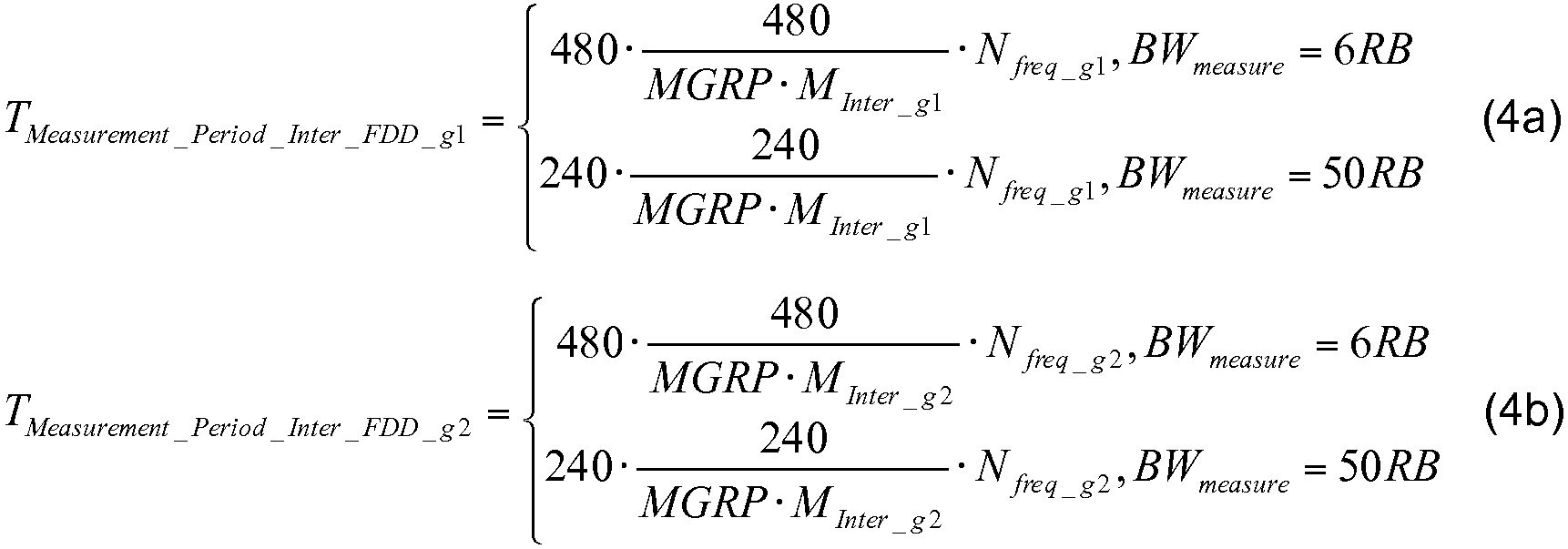
수식 1a 및 1b(총괄적으로 "수식 1")는 제 1 정규의 성능 그룹 g1 및 제 2 감소된 성능 그룹 g2에 대해 각각 주파수 계층(90)을 측정하기 위해 UE(50)에 이용가능한 최소 요건(최대 시간)을 표현한다. ![]()
![]()
![]()
![]()
![]()
![]()
![]()
![]()
![]()
![]()
![]()
![]()
![]()
![]()
평균하여, ![]()
![]()
![]()
![]()
![]()
![]()
![]()
![]()
수식 1로부터, 측정 갭의 수 ![]()
![]()
![]()
![]()
![]()
![]()
![]()
![]()
![]()
![]()
LTE 규격에서, UE(50)는 통상적으로 2개의 상이한 측정 기회를 갖는다. 첫째로, 480 ms당 12개의 측정 갭이 존재하고; 따라서 매 40ms마다 하나의 측정 갭 및 그에 따른 하나의 측정 기회가 존재한다(480 ms / 12 = 40 ms). 둘째로, 480 ms당 6개의 측정 갭이 존재하고; 따라서 매 80 ms마다 하나의 측정 갭/기회가 존재한다 (480 ms / 6 = 80 ms). 따라서, ![]()
![]()
![]()
![]()
주파수 계층의 UE(50)에 의해 취해지는 측정은, 도 3에 예시된 바와 같이 UE(50)와 무선 HetNet(200)의 다른 엔티티 사이에서이다. 각각의 측정은 주파수 계층(90)의 일부 특성을 계산한다. 일반적으로, 이러한 특성은 신호 대 간섭 플러스 잡음비, 즉 SINR이다. LTE 환경에서, SINR은, 신호 강도로 고려될 수 있는 기준 신호 수신 전력(RSRP) 및 본질적으로 주파수 계층(90)의 간섭인 기준 신호 수신 품질(RSRQ) 둘 모두를 측정함으로써 효과적으로 획득된다.The measurements taken by the
RSRP 및 RSRQ 측정에 있어서, 물리 계층 측정 기간 ![]()
![]()
![]()
![]()
로서 주어져서 정의되고, 여기서 ![]()
![]()
가정home
모니터링되고 있는 각각의 주파수 계층(90)에 있어서, UE(50)는 먼저 식별을 수행하고, 그 다음 측정을 취한다. 식별은 또한 동기화로서 공지되고, 여기서 UE(50)는 주파수 계층(90)에 대한 동기화 심볼을 검출한다. LTE에서, 동기화 심볼은 1차 동기화 심볼(PSS) 또는 2차 동기화 심볼(SSS)로서 주어진다. 오직 동기화가 발생한 이후에만 UE(50)가 주파수 계층(90)의 측정을 수행할 수 있다.For each frequency layer 90 being monitored, the
일부 실시예에서, PCIM 방법(100)은, 정규의 성능 그룹에서 측정되고 있는 주파수 계층(90)이 감소된 성능 그룹의 주파수 계층보다 더 엄격한 요건을 향유하는 것을 보장한다. 앞서 표시된 바와 같이, ![]()
![]()
![]()
![]()
![]()
![]()
수식 5는, UE(50)가 감소된 성능 그룹 g2에서보다 정규의 성능 그룹 g1에서 주파수 계층(90)을 더 신속하게 식별하기 위한 선호도를 표시한다.
또한, ![]()
![]()
![]()
![]()
![]()
![]()
등가 함수Equivalent function
일부 실시예에서, 상기 수식 1 내지 수식 3을 이용하면, 등가 함수는,In some embodiments, using Equations 1 to 3 above,

로서 주어진다..
수식 7a는,Equation (7a)
![]()
![]()
로 재기록될 수 있다.Lt; / RTI >
수식 2 및 수식 3 뿐만 아니라 수식 5, 수식 6 및 수식 7에서 주어진 가정을 이용하면, PCIM 방법(100)의 하기 실시예가 설명된다. 추가로, 본원에서 설명되는 네트워크는, 도 3의 HetNet 네트워크(200)와 같은 이종 네트워크인 것으로 가정된다. 그럼에도 불구하고, LTE 규격 하에서 동작하는 (오직 매크로 eNB만을 포함하는) 동종 네트워크와 같은 다른 무선 네트워크가 또한 PCIM 방법(100)을 이용할 수 있다.Using the assumptions given in
실시예Example 1 One
PCIM 방법(100)은, 운영자 및/또는 네트워크 판매자(예를 들어, AT&T, Ericsson 또는 Huawai)가, ![]()
![]()
![]()
![]()
![]()
![]()
일부 실시예에서, 정규의 및 감소된 성능 그룹이 정의되는 경우, 정규의 성능 그룹의 크기 ![]()
![]()
![]()
![]()
![]()
![]()
![]()
![]()
![]()
![]()
PCIM 방법(100)의 실시예 1은 도 5의 흐름도에 예시된다. 네트워크 운영자는 UE에 의해 측정되는 주파수 계층(90)의 수를 정의한다(블록(302)). 서빙 eNB(20)는 정규의 성능 그룹에서 주파수 계층(90)의 수를 정의한다(블록(304)). 감소된 성능 그룹에서 주파수 계층(90)의 수를 유도하기 위해 수식 3이 이용된다(블록(306)). UE(50)에 의해 수행되는 측정의 주기 MGRP는 40 ms 또는 80 ms로 선택된다(블록(308)). 이러한 선택은, UE(50), pcell eNB(20A) 또는 다른 네트워크 엔티티에 의해 행해진다.Example 1 of the PCIM method 100 is illustrated in the flow chart of FIG. The network operator defines the number of frequency layers 90 as measured by the UE (block 302). The serving
이러한 값이 확인되면, 정규의 성능 그룹에 대해 발생하는 측정의 밀도를 결정하기 위해 수식 7이 이용된다(블록(310)). 마지막으로, 감소된 성능 그룹에 대한 측정의 밀도를 유도하기 위해 수식 2가 이용된다(블록(312)). PCIM 방법(100)의 실시예 1에 의해 수행되는 동작이 완료된다.Once these values are identified,
따라서, PCIM 방법(100)은, eNB(20)가 수식 7에 기초하여 (수식 2 및 수식 3의 도움으로) 정규의 성능 그룹의 크기를 판정하게 하는 설계 기준을 제공한다.Thus, the PCIM method 100 provides a design criteria that allows the
실시예Example 2 2
제 2 실시예에서, 전반적 측정 지연을 최소화하기 위해, PCIM 방법(100)은 모니터링되는 모든 주파수 계층(90)을 단일 그룹에 할당하고, 모든 자원은 동일한 그룹에 할당된다. 동일한 실시예에서, 이러한 할당은 eNB에 의해 행해진다. 다른 실시예에서, 할당은 UE에 의해 행해진다. 이것은, UE(50)가, 예를 들어, 하나의 주파수 계층을 다른 주파수 계층에 비해 우선순위화하도록 허용한다.In the second embodiment, in order to minimize the overall measurement delay, the PCIM method 100 allocates all monitored frequency layers 90 to a single group, and all resources are assigned to the same group. In the same embodiment, this assignment is made by the eNB. In another embodiment, the assignment is made by the UE. This allows the
일반적으로, 정규의 성능 및 감소된 성능 그룹이 정의되는 방법과 무관하게, 주파수간 및 RAT간 측정과 각각 관련된 전반적인 측정 지연을 감소시키는 것이 바람직하다. UE(50)에 의한 적시의 측정 및 보고는 네트워크 동작을 용이하게 할 뿐만 아니라 무선 링크 실패(RLF), 예를 들어, 접속 손실의 확률을 감소시킨다. 이것은, 서빙 셀 커버리지가 약한 경우에 특히 해당한다.In general, it is desirable to reduce the overall measurement delay associated with inter-frequency and inter-RAT measurements, respectively, irrespective of how normal performance and reduced performance groups are defined. Timely measurement and reporting by the
높은 및 감소된 성능 그룹에 대한 최대 셀 식별 지연은, UE(50)가 셀(주파수 계층(90))을 식별할 수 있는 시간 기간인 ![]()
![]()
![]()
![]()
![]()
![]()
![]()
![]()
으로 정량화될 수 있다.Lt; / RTI >
또한, ![]()
![]()
![]()
![]()
![]()
![]()

으로 정량화될 수 있다.Lt; / RTI >
표 1은, 몇몇 상이한 정규의 성능 그룹 크기 ![]()
![]()
![]()
![]()

표 1의 마지막 행은, 모니터링되는 랜덤으로 선택된 주파수 ![]()
![]()
![]()
![]()
![]()
![]()
![]()
![]()
PCIM 방법(100)의 실시예 2는 도 6의 흐름도에서 예시된다. 측정되는 모든 주파수 계층은 정규의 성능 그룹의 일부이다(블록(402)). 이것은 UE(50) 또는 eNB(20)에 의해 행해질 수 있다. 감소된 성능 그룹은 비어 있다(블록(404)). UE(50)에 의해 수행되는 측정의 주기 MGRP는 UE(50)에 의해 40 ms 또는 80 ms로 선택된다(블록(406)). 정규의 성능 그룹에 대해 측정이 발생하는 밀도를 유도하기 위해 수식 7이 이용된다(블록(408)). PCIM 방법(100)의 실시예 2에 의해 수행되는 동작은 완료된다.Example 2 of the PCIM method 100 is illustrated in the flow chart of FIG. All frequency layers being measured are part of the regular performance group (block 402). This may be done by the
실시예Example 3 3
PCIM 방법(100)은 또한 UE(50)의 하위호환가능 성능을 고려한다. 실시예 3은, 정규의 성능 그룹 g1이, 측정 지연의 관점에서 적어도 레거시 시스템 성능을 달성하게 한다. 레거시 UE는, UE(50)(예를 들어, ![]()
![]()
![]()
![]()
하위호환가능 성능을 달성하기 위해, 하기 2개의 선택 중 하나가 실시예 3에서 이용가능하다.In order to achieve backward compatible performance, one of the following two choices is available in Example 3:
· 모드 1: 정규의 성능 그룹 g1은, MGRP = 40 ms인 경우 480 ms 내에 할당된 7개의 측정 갭을 갖는 4개의 주파수로 이루어진다.Mode 1: The normal performance group g1 consists of four frequencies with seven measurement gaps allocated within 480 ms for MGRP = 40 ms.
· 모드 2: 정규의 성능 그룹 g1은, MGRP = 80 ms인 경우 480 ms 내에 할당된 4개의 측정 갭을 갖는 5개의 주파수로 이루어진다.Mode 2: The normal performance group g1 consists of five frequencies with four measurement gaps allocated within 480 ms for MGRP = 80 ms.
이러한 수가 수식 7에 대입되면, 다음과 같이 모드 1에 대해: 4/7 ≤ 1; 모드 2에서: 5/4 ≤ 2가 획득된다. 수식 둘 모두가 참이다. 따라서, 실시예 3에서 모드 1 및 모드 2 둘 모두가 수식 7을 충족한다.If this number is substituted into
코어 및 성능 하위호환가능성은 UE(50) 구현 및 네트워크 동작 관점 둘 모두에 대해 중요하다. 기존의 주파수간/RAT간 측정 지연 요건은 RAN4 릴리스 8 이후 개발되어 왔다. 이들의 견고성 및 지속성은 이 기술분야에서 양호하게 승인되어 왔다. 따라서, 일부 실시예에서, 모니터링되는 주파수의 수가 상당히 증가되더라도, 모니터링되는 주파수, 예를 들어, 정규의 성능 캐리어(90) 중 (전부가 아니더라도) 일부가 레거시 UE 성능에 비교된 기존의 최소 성능 요건을 달성할 수 있는 것을 보장하는 것이 바람직하다. 예를 들어, UE(50)가 고속으로 이동중인 경우(예를 들어, 열차 또는 다른 차량에서 동작되는 경우) 및/또는 서빙 셀 커버리지가 열악한 경우, 2개의 선택 중 하나가 선호될 수 있다. 대응적으로, 일부 실시예에서, 하기 공식은, 정규의 성능 캐리어가 레거시 성능 요건을 달성할 수 있는 것을 보장하는 방법을 제시한다.Core and performance backwards compatibility is important for both

MGRP = 40 ms인 경우, 하기 (![]()
![]()

표 2의 엔트리 중 하나인 (![]()
![]()
유사하게, MGRP = 80 ms인 경우, 하기 (![]()
![]()

표 3의 엔트리 중 하나인 (![]()
![]()
정규의 성능 그룹 성능에 추가로, UE(50)가 정규의 성능 그룹에서 더 많은 주파수(90)를 신속하게 측정 및 보고할 수 있도록, 정규의 성능 그룹 크기를 최대화하는 것이 또한 바람직하다. 한편, 전반적인 측정 지연을 또한 유지하는 것이 또한 중요하다. 그 결과, 일부 실시예에서, 대응하는 그룹 및 자원 할당이 추천된다.In addition to the regular performance group performance, it is also desirable to maximize the normal performance group size so that the

표 4는, 표 2 및 표 3에 기초한다. 측정되는 주파수 계층(90)의 수 ![]()
![]()
![]()
![]()
![]()
![]()
PCIM 방법(100)의 실시예 3은 도 7의 흐름도에서 예시된다. 모드 1과 모드 2 사이의 선택이 행해진다(블록(502)). 모드 1이 선택되는 경우, 정규의 성능 그룹의 주파수 계층(90)의 수는 4이고(블록(504)), 정규의 성능 그룹의 측정 갭의 수는 480 ms당 7이고(블록(506)), MGRP는 40 ms이다(블록(508)). 따라서, UE(50)는, 하위호환가능성을 달성하기 위해 주파수 계층 측정이 수행되게 하는 관련 정보를 갖는다.Example 3 of the PCIM method 100 is illustrated in the flow chart of FIG. A selection is made between mode 1 and mode 2 (block 502). If mode 1 is selected, then the number of frequency layers 90 in the regular performance group is 4 (block 504) and the number of measurement gaps in the regular performance group is 7 per 480 ms (block 506) , And MGRP is 40 ms (block 508). Thus, the
모드 2가 대신 선택되는 경우, 정규의 성능 그룹의 주파수 계층(90)의 수는 5이고(블록(510)), 정규의 성능 그룹의 측정 값의 수는 480 ms당 4이고(블록(512)), MGRP는 40 ms이다(블록(514)). 따라서, UE(50)는, 하위호환가능성을 달성하기 위해 주파수 계층 측정이 수행되게 하는 관련 정보를 갖는다. 이 실시예에서 2개의 이용가능한 모드를 가짐으로써, UE(50)의 시스템 설계는 크게 단순화될 수 있다.If the mode 2 is selected instead, the number of frequency layers 90 in the regular performance group is 5 (block 510) and the number of measurements in the regular performance group is 4 per 480 ms (block 512) ) And MGRP is 40 ms (block 514). Thus, the
실시예Example 4 4
이론적으로, UE(50)에 의해 모니터링되고 있는 주파수 계층의 수의 증가를 처리할 때, eNB(20)는, 각각의 그룹 g1 및 g2에 대해, 정규의 성능 그룹 g1의 크기(![]()
![]()
![]()
![]()
![]()
![]()
UE(50) 구현의 관점에서, 그룹 크기(![]()
![]()
![]()
![]()
표 5는, 모든 주파수 계층이 정규의 성능 그룹에 할당되고, 480 ms당 정규의 성능 그룹에 대한 측정 갭의 수 ![]()
![]()
![]()
![]()
![]()
![]()
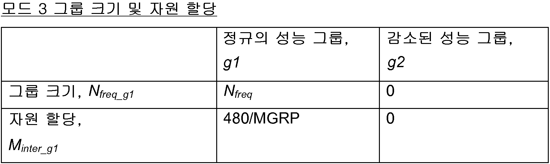
표 6은, 모드 4 및 모드 5로서 표시되는 제 2 및 제 3 모드를 제시한다. 모드 4에서, MGRP는 40 ms이다. 모드 4에서, 정규의 성능 그룹에 대한 그룹 크기 ![]()
![]()
![]()
![]()
![]()
![]()
![]()
![]()
![]()
![]()
![]()
![]()

일부 실시예에서, 모드 4 및 모드 5는, 얼마나 많은 주파수 계층이 모니터링되는지와 무관하게 정규의 성능 그룹의 크기를 고정시키도록 설계된다. UE(50)는 모드 선택이 언제 행해지는지를 참조하기 위해 표 6을 갖는다. 신호가 수신되는 경우(또는 사전정의된 비트가 설정되는 경우), UE(50)는 모드 3(표 5)에 따라 동작하는 것을 인식한다. 신호가 수신되지 않는 경우(또는 비트가 클리어되는 경우), UE(50)는 표 6을 참조하고, 모드 4 또는 모드 5에 따라 동작한다.In some embodiments,
PCIM 방법(100)의 실시예 4는 도 8의 흐름도에 예시된다. 신호가 수신되면, 비트가 설정되어 모드 3을 표시하는 한편, 신호가 수신되지 않으면 비트가 클리어되어 모드 4 또는 모드 5를 표시한다(블록(602)). 모드 3이 표시되면, 모든 주파수 계층은 정규의 성능 그룹에 할당되고(블록(604)), 자원 할당은 480/MGRP로 설정되고(블록(606)), 이것은, UE(50)가 이용할 MGRP(예를 들어, 40 ms 또는 80 ms)를 판정하게 한다(블록(608)).Example 4 of the PCIM method 100 is illustrated in the flow chart of FIG. When a signal is received, the bit is set to indicate mode 3, while if the signal is not received, the bit is cleared to indicate
신호가 수신되지 않거나 비트가 클리어되면, 모드 4 또는 모드 5가 표시된다. UE(50)가 MGRP = 40 ms를 이용하는 것으로 판정하면, 이것은 모드 4를 표시한다(블록(610)). 표 6으로부터, 정규의 성능 그룹의 주파수의 수는 4이고(블록(612)), 정규의 성능 그룹에 대한 자원 할당은 7이다(블록(614)). UE(50)가 80 ms의 MGRP를 이용하는 것으로 판정하면, 이것은 모드 5를 표시한다. 표 6으로부터, 정규의 성능 그룹의 주파수의 수는 5이고(블록(616)), 정규의 성능 그룹에 대한 자원 할당은 4이다(블록(618)). 이러한 실시예에서 3개의 이용가능한 모드를 가짐으로써, UE(50)의 시스템 설계는 크게 단순화될 수 있다.When the signal is not received or the bit is cleared,
실시예Example 5 5
UE(50)가 네트워크로부터 측정할 주파수 계층의 리스트를 수신함을 상기한다. 예를 들어, 네트워크는 10개의 주파수 계층의 리스트, 즉, 대역 1 내지 대역 10을 UE(50)에 전송할 수 있지만, 주파수 계층은, 우선순위 순서로, 즉, 대역 7, 대역 3, 대역 4, 대역 8, 대역 2, 대역 1, 대역 10, 대역 9, 대역 5 및 대역 6의 순서로 전송될 수 있다. 일부 실시예에서, ![]()
![]()
예를 들어, 인덱스가 리스트의 제 3 엔트리 상에 있으면, UE(50)는, 대역 7, 3 및 4가 정규의 성능 그룹에 있는 한편, 대역 8, 2, 1, 10, 9, 5 및 6이 감소된 성능 그룹에 있음을 자동적으로 인식한다.For example, if the index is on the third entry in the list, the
추가로, 일부 실시예에서, 일 비트 신호가, 그룹 크기 ![]()
![]()
![]()
![]()
![]()
![]()
![]()
![]()
요약하면, 실시예 5는 다음을 제공한다:In summary, Example 5 provides the following:
· 단일 측정 리스트가 UE에 제공된다.A single measurement list is provided to the UE.
○ 어떠한 명시적인 정규의 성능 및 감소된 성능 그룹도 별개로 UE에 제공되지 않는다. No explicit normal performance and reduced performance group are provided separately for the UE.
· 측정 리스트의 주파수는 내림차순으로 우선순위화된다.• The frequencies of the measurement list are prioritized in descending order.
· 그룹 크기 및 자원 할당 결합 모드를 UE(50)에 표시하기 위해 1-비트 시그널링이 도입된다:One-bit signaling is introduced to indicate to the
○ 모드 6에서: 오직 하나의 그룹(즉, 정규의 성능 그룹)만이 존재한다. In mode 6: there is only one group (i.e., normal performance group).
○ 모드 7 및 모드 8에서: 정규의 성능 그룹에 대한 크기 및 자원 할당은 고정된다. 정확한 값은, 표 6에서 주어지는 MGRP에 의존한다.
In
PCIM 방법(100)의 실시예 5는 도 9의 흐름도에 예시된다. 측정 리스트는, UE(50)에 공급되는 측정된 주파수 계층의 우선순위화된 리스트로 이루어진다(블록(702)). 측정 리스트로의 인덱스 ![]()
![]()
대신에 신호가 수신되지 않거나 비트가 클리어되면(블록(706)), UE(50)는 상기 표 6에 따라 모드 7 또는 모드 8에서 동작한다. MGRP가 40 ms가 아니면(블록(714)), UE(50)는 모드 7에서 동작한다. 정규의 성능 그룹의 주파수 계층의 수는 5이고(블록(716)), 자원 할당은 4이다(블록(718)). 그렇지 않으면, MGRP는 40 ms이고(블록(714)), 정규의 성능 그룹의 주파수 계층의 수는 4이고(블록(720), 자원 할당은 7이다(블록(722)). 이러한 실시예에서 3개의 이용가능한 모드를 가짐으로써, UE(50)의 시스템 설계는 크게 단순화될 수 있다.Instead, if the signal is not received or the bit is cleared (block 706), the
실시예Example 6 6
실시예 6은, UE(50)가 고속으로 이동중인 상황에 매우 적합하다. 실시예 6에서, UE(50)는 높은 및 감소된 성능 그룹 지정을 동적으로 변경할 수 있다. 고속으로 이동하면, UE(50)는 주파수 계층 및 측정 요건을 감소된 성능 그룹으로 이동시킬 수 있다. UE 속력에 따라 주파수 계층의 할당을 적응시킴으로써, 일부 실시예에서, 정규의 성능 그룹에서 측정 지연은 관리가능하게 된다. 예를 들어, 고속 열차에서와 같이 UE(50)가 고속으로 이동중인 상황에서, 측정은, UE가 유휴 위치에 안착된 경우보다 더 빠를 필요가 있다. 따라서, 정규의 성능 그룹의 크기는 이러한 환경 하에서는 적절히 감소될 수 있다.
일부 실시예에서, UE(50)는, 본원에서 설명되는 실시예 중 임의의 실시예 또는 전부를 구현할 능력을 가질 수 있다. 다른 실시예에서, UE(50)는 상기 실시예 중 오직 일부로만 능력이 제한된다. 실용적으로 말해서, UE(50)는 초기화 스테이지에서 실시예 중 하나를 채택하고 그 후 변경하지 않을 것이다. 그러나, UE(50)가 고속으로 이동중인 실시예 6에서와 같이, UE(50)가 자신의 구성을 변경하는 것이 타당한 환경이 존재할 수 있다. 어느 경우이든, UE에 의해 행해지는 구성에서의 임의의 변경은, 이러한 변경과 연관된 시그널링 오버헤드가 존재하기 때문에, 일부 실시예에서 준-정적이다.In some embodiments, the
도 10a 및 도 10b는, eNB(20) 및 UE(50)(둘 모두는 트랜시버임)를 포함하는 무선 이웃(800)의 단순화된 블록도이다. eNB(20) 및 UE(50)는 일부 실시예에 따라 앞서 설명된 PCIM 방법(100)을 이용한다. 이 예에서, eNB(20)는 송신기로서 동작하고, UE(50)는 수신기로서 동작한다. 도 10a는 eNB(20) 및 UE(50)의 소프트웨어-기반 버전을 도시하는 한편, 도 10b는 ASIC-기반 버전을 도시한다.10A and 10B are simplified block diagrams of a
먼저 도 10a를 보면, 각각의 디바이스는 안테나(154), 프론트-엔드(132), 무선(136), 기저대역 디지털 신호 프로세서(DSP)(138) 및 매체 액세스 제어기(MAC)(130)를 포함한다. 두 디바이스 모두는 각각의 디바이스에 도시된 하드웨어를 갖지만, eNB(20)는 자신의 프론트-엔드(132)에 전력 증폭기(146)를 갖는 것으로 도시된 한편, UE(50)는 자신의 프론트-엔드에 저잡음 증폭기(148)를 포함한다. eNB(20)는 디지털-투-아날로그 변환기(DAC)(134)를 포함하는 한편, UE(50)는 아날로그-투-디지털 변환기(ADC)(142)를 포함한다. UE(50)는 가상적으로 임의의 무선 디바이스, 예를 들어, 랩탑 컴퓨터, 셀룰러 폰, 또는 다른 무선 시스템일 수 있고, 송신기(송신 모드)로서 또는 수신기(수신 모드)로서 동작할 수 있다.10a, each device includes an
MAC(130)는 내장된 중앙 처리 장치(CPU)(124) 및 데이터 메모리(120)를 포함하여, 그 일부가 소프트웨어-기반인 PCIM 방법(100)은, 일부 실시예에서, 메모리에 로딩되고 CPU에 의해 실행될 수 있다. 도 10a의 도시는 MAC(130)의 단순화된 표면이고, MAC의 일부일 수 있는 다른 디바이스, 회로 및 로직 엘리먼트는 생략된다.The
MAC(130)는, 송신기 및 수신기에서 통상적으로 발견되는 로직 디바이스, 즉, 프론트-엔드(132), DAC(134), ADC(142), 무선(136) 및 DSP(138)와 인터페이싱한다. 디바이스(132, 134, 136, 138 및 142)는 또한 본원에서 타겟 모듈로서 공지된다. 타겟 모듈 뿐만 아니라 MAC(130) 내의 로직 디바이스는, 하드웨어, 소프트웨어, 또는 하드웨어 및 소프트웨어 컴포넌트의 결합으로 이루어질 수 있다.The
타겟 모듈은 통상적으로 대부분의 송신기 및 수신기에서 발견된다. FE(132)는 안테나(154)에 접속되고, 전력 증폭기(PA)(송신기의 경우), 저잡음 증폭기(LNA)(수신기의 경우), 및 송신기 모드와 수신기 모드 사이에서 스위칭하기 위한 안테나 스위치(미도시)를 포함한다. DAC(134)는, DSP(138)로부터 착신된 디지털 신호를 무선장치(송신기)를 통한 송신에 앞서 아날로그 신호로 변환하기 위해 이용되고; 반대로, ADC(142)는 무선로부터 착신된 아날로그 신호를 DSP(138)(수신기)에 의한 프로세싱 전에 디지털 신호로 변환하기 위해 이용된다. eNB(20)에서, 무선장치(136)는 신호를 기저대역으로부터 캐리어 주파수로 전송하고; UE(50)에서, 무선장치(136)는 신호를 캐리어 주파수로부터 기저대역으로 전송한다. UE(50)에서, DSP(138)는, MAC(130)에 의한 프로세싱을 위해 ADC(142)로부터의 OFDM 신호를 복조한다. eNB(20)에서, DSP(138)는 MAC 신호를 기저대역 주파수의 OFDM 신호로 변조하고, 결과적 신호를 DAC(134)에 전송한다.Target modules are typically found in most transmitters and receivers. FE 132 is connected to
통상적인 송신 동작은 다음과 같이 발생한다: eNB(20)에서, MAC(130)는 DSP(138)에 패킷을 전송한다. DSP(138)는 패킷을 디지털 OFDM 신호로 변환하고 이를 DAC(134)에 전송한다. DAC(134)는 이 신호를 아날로그 신호로 변환하고, 이 신호를 무선(136)에 전송한다. 무선장치(136)는 기저대역 신호를 캐리어 주파수로 변조하고, 이 신호를 프론트-엔드(132)의 전력 증폭기(146)에 전송하고, 전력 증폭기(146)는 안테나(154)를 통한 공중을 통한 송신에 적합하도록 신호를 증폭한다.A typical transmission operation occurs as follows: At the
UE(50)에서, 신호는 안테나(154)에 의해 수신된다. 약한 아날로그 신호가 프론트-엔드(132)의 저잡음 증폭기(148)로 수신되고, 저잡음 증폭기(148)는 증폭된 아날로그 신호를 무선장치(136)에 전송하고, 무선장치(136)는 선택된 주파수 대역에 따라 신호를 필터링하고 캐리어 주파수 신호를 기저대역 신호로 복조한다. 무선장치(136)는 아날로그 신호를 ADC(142)에 전송하고, ADC(142)는 아날로그 신호를, DSP(138)에 의한 프로세시에 적합한 디지털 신호로 변환한다. DSP(138)는 OFDM 신호를 복조하고, 이 신호를 MAC(130) 패킷 바이트로 변환한다. 다른 동작들, 예를 들어, 패킷의 암호화 및 암호해독은 도시되지 않는다. 송신이 성공적인 경우, UE(50)의 MAC(130)에 의해 수신된 패킷은 eNB(20)의 MAC(130)에 의해 송신된 패킷과 동일하다.At the
다른 실시예에서, 도 10b에 도시된 바와 같이, eNB(20) 및 UE(50)는 MAC(130)에 CPU(124)를 포함하지 않는다. 그 대신, 주문형 집적 회로(ASIC)(190)가 로직 레지스터(192)를 이용하여 구현되는 상태 머신으로서 PCIM 방법(100)을 구동할 수 있다. 도 10b의 ASIC 솔루션은, 예를 들어, 저전력 소모가 중요한 시스템에서는, 도 10a의 MAC-기반 구현에 비해 선호될 수 있다.In another embodiment,
본 출원은 제한된 수의 실시예에 대해 설명되었지만, 당업자들은, 이로부터 다수의 변형 및 변화를 인식할 것이다. 첨부된 청구항은 모든 이러한 변형 및 변화를 본 발명의 진정한 사상 및 범주 내에 속하는 것으로 커버하는 것으로 의도된다.While the present application has been described with respect to a limited number of embodiments, those skilled in the art will recognize many variations and modifications thereof. It is intended that the appended claims cover all such modifications and variations as falling within the true spirit and scope of the invention.
Claims (25)
상기 명령어는, 실행 시에,
적어도 하나의 진화된 노드 B(eNB) 트랜시버를 포함하는 무선 이웃에서 동작하는 사용자 장비(UE)에 의해, 그룹의 주파수 계층을 측정하는 것 ―상기 그룹의 크기는 상기 그룹에 할당된 주파수 계층의 수로서
상기 그룹에 할당되는 주파수 계층의 측정을 가능하게 하기 위해 측정 갭의 제 2 수
을 수행하고,
상기
비일시적 컴퓨터 판독가능 저장 매체.
18. A non-transitory computer readable storage medium having stored thereon instructions executable by a processor,
Wherein the instructions, when executed,
Measuring a frequency layer of a group by a user equipment (UE) operating in a wireless neighbor comprising at least one evolved Node B (eNB) transceiver, the size of the group being determined by the number of frequency layers as
To enable the measurement of the frequency layer assigned to the group, a second number of measurement gaps
Lt; / RTI >
remind
Non-volatile computer readable storage medium.
상기 그룹의 크기
비일시적 컴퓨터 판독가능 저장 매체.
The method according to claim 1,
The size of the group
Non-volatile computer readable storage medium.
상기 그룹은 상기 UE와 상기 UE의 서빙 eNB 사이의 서빙 주파수 계층을 포함하지 않는
비일시적 컴퓨터 판독가능 저장 매체.
The method according to claim 1,
The group comprising a serving frequency layer between the UE and a serving eNB of the UE
Non-volatile computer readable storage medium.
상기

을 이용하여 획득되는
비일시적 컴퓨터 판독가능 저장 매체.
The method according to claim 1,
remind
Obtained using
Non-volatile computer readable storage medium.
상기 그룹은 상기 무선 이웃 내의 다른 기지국과 상기 UE 사이의 주파수 계층을 포함하는
비일시적 컴퓨터 판독가능 저장 매체.
The method according to claim 1,
The group comprising a frequency layer between another base station in the wireless neighborhood and the UE
Non-volatile computer readable storage medium.
상기 그룹은, 상기 UE가 동작하는 현재의 무선 액세스 기술(radio access technology, RAT) 내의 주파수 계층을 포함하는
비일시적 컴퓨터 판독가능 저장 매체.
The method according to claim 1,
The group includes a frequency layer within a current radio access technology (RAT) in which the UE is operating
Non-volatile computer readable storage medium.
상기 그룹은, 상기 무선 이웃 내의 제 2 UE와 상기 eNB 사이의 주파수 계층을 포함하는
비일시적 컴퓨터 판독가능 저장 매체.
The method according to claim 6,
The group comprising a frequency layer between a second UE in the wireless neighbor and the eNB
Non-volatile computer readable storage medium.
상기 그룹은, 상기 무선 이웃 내의 제 2 UE와 제 2 eNB 사이의 주파수 계층을 포함하는
비일시적 컴퓨터 판독가능 저장 매체.
The method according to claim 6,
The group comprising a frequency layer between a second UE and a second eNB in the wireless neighbor
Non-volatile computer readable storage medium.
상기 무선 이웃은, 상기 UE의 무선 액세스 기술(RAT)에서 동작하는 엔티티 및 상기 UE와는 상이한 RAT에서 동작하는 다른 엔티티를 포함하는 이종(heterogeneous) 네트워크인
비일시적 컴퓨터 판독가능 저장 매체.
The method according to claim 1,
The wireless neighbor is a heterogeneous network comprising an entity operating in the radio access technology (RAT) of the UE and another entity operating in a different RAT than the UE
Non-volatile computer readable storage medium.
상기 그룹의 주파수 계층 중 하나 이상은 상기 UE의 현재의 RAT 외부에 있는
비일시적 컴퓨터 판독가능 저장 매체.
10. The method of claim 9,
Wherein at least one of the frequency layers of the group is located outside the current RAT of the UE
Non-volatile computer readable storage medium.
상기 그룹은 상기 무선 이웃 내의 제 2 UE와 상기 UE 사이의 주파수 계층을 포함하는
비일시적 컴퓨터 판독가능 저장 매체.
The method according to claim 1,
The group comprising a frequency layer between a second UE and the UE in the wireless neighbor
Non-volatile computer readable storage medium.
무선 네트워크의 진화된 NodeB(eNB)로부터, 그룹에 할당되는 주파수 계층의 수
상기 UE는 상기 UE에 의해 결정되는 측정 갭 반복 기간(MGRP)에 따라 상기 그룹의 주파수 계층을 측정하고,
상기
사용자 장비(UE).
A user equipment (UE) used in a wireless network,
From the evolved NodeB (eNB) of the wireless network, the number of frequency layers allocated to the group
The UE measures the frequency layer of the group according to a measurement gap repetition period (MGRP) determined by the UE,
remind
User Equipment (UE).
상기 그룹의 주파수 계층은 상기 UE와 상기 UE의 서빙 eNB 사이의 서빙 주파수 계층을 포함하지 않는
사용자 장비(UE).
13. The method of claim 12,
Wherein the frequency layer of the group does not include a serving frequency layer between the UE and the serving eNB of the UE
User Equipment (UE).
상기

을 이용하여 획득되는
사용자 장비(UE).
13. The method of claim 12,
remind
Obtained using
User Equipment (UE).
상기 그룹은,
상기 UE와 제 2 eNB 사이의 주파수 계층;
상기 UE가 동작하는 현재의 무선 액세스 기술(RAT) 내의 주파수 계층;
상기 eNB와 제 2 UE 사이의 주파수 계층;
제 2 UE와 제 2 eNB 사이의 주파수 계층;
상기 UE의 현재의 무선 액세스 기술 외부의 주파수 계층; 및
상기 UE와 제 2 UE 사이의 주파수 계층
으로 이루어진 그룹으로부터 선택되는 주파수 계층을 포함하는
사용자 장비(UE).
13. The method of claim 12,
Wherein the group comprises:
A frequency layer between the UE and the second eNB;
A frequency layer within a current radio access technology (RAT) in which the UE is operating;
A frequency layer between the eNB and the second UE;
A frequency layer between the second UE and the second eNB;
A frequency layer outside the current radio access technology of the UE; And
The frequency layer between the UE and the second UE
Lt; RTI ID = 0.0 > a < / RTI > frequency layer
User Equipment (UE).
상기 명령어는, 실행 시에,
무선 이웃 내의 UE에 의해 측정될 사전결정된 수의 대역을 식별하는 것 ―상기 사전결정된 수의 대역의 서브세트는 제 1 그룹에 할당되고, 상기 사전결정된 수의 대역은 서빙 셀 대역을 포함하지 않음― 과,
상기 제 1 그룹에 대한 사전정의된 그룹 크기, 측정 갭 반복 기간(MGRP) 및 측정 갭의 수를 선택하는 것과,
상기 MGRP 및 상기 측정 갭의 수를 이용하여, 상기 제 1 그룹에서 상기 대역의 주기적 측정을 수행하는 것
을 수행하는
비일시적 컴퓨터 판독가능 저장 매체.
18. A non-transitory computer readable storage medium having stored thereon instructions executable by a processor,
Wherein the instructions, when executed,
Identifying a predetermined number of bands to be measured by a UE in a wireless neighbor, the subset of the predetermined number of bands being assigned to a first group, the predetermined number of bands not including a serving cell band, and,
Selecting a predefined group size, a measurement gap repetition period (MGRP) and a number of measurement gaps for the first group,
Performing periodic measurements of the band in the first group using the MGRP and the number of measurement gaps
To do
Non-volatile computer readable storage medium.
상기 제 1 그룹의 사전정의된 크기는 4이고, 상기 측정 갭의 수는 7이고, 상기 MGRP는 40 밀리초(ms)인
비일시적 컴퓨터 판독가능 저장 매체.
17. The method of claim 16,
Wherein the predefined size of the first group is 4, the number of measurement gaps is 7, the MGRP is 40 milliseconds (ms)
Non-volatile computer readable storage medium.
상기 제 1 그룹의 사전정의된 크기는 5이고, 상기 측정 갭의 수는 4이고, 상기 MGRP는 80 밀리초(ms)인
비일시적 컴퓨터 판독가능 저장 매체.17. The method of claim 16,
Wherein the predefined size of the first group is 5, the number of measurement gaps is 4, the MGRP is 80 milliseconds (ms)
Non-volatile computer readable storage medium.
상기 대역의 주기적 측정은 기준 신호 수신 전력(RSRP) 및 기준 신호 수신 품질(RSRQ)을 포함하는
비일시적 컴퓨터 판독가능 저장 매체.
17. The method of claim 16,
The periodic measurement of the band includes a reference signal received power (RSRP) and a reference signal reception quality (RSRQ)
Non-volatile computer readable storage medium.
상기 제 1 그룹에 할당되지 않는 대역을 포함하는 제 2 그룹을 더 포함하고,
상기 제 2 그룹의 크기는, 상기 사전결정된 수로부터 감산된 상기 제 2 그룹의 사전정의된 크기인
비일시적 컴퓨터 판독가능 저장 매체.
17. The method of claim 16,
And a second group including a band not allocated to the first group,
Wherein the size of the second group is less than the predefined size of the second group subtracted from the predetermined number
Non-volatile computer readable storage medium.
상기 명령어는, 실행 시에,
롱 텀 에볼루션(LTE) 무선 액세스 기술(RAT)에서 동작하는 사용자 장비(UE)에 의해, 상기 UE에 의해 측정될 주파수 대역의 리스트를 수신하는 것 ―상기 리스트로의 인덱스는, 상기 리스트의 어느 주파수 대역이 제 1 그룹에 할당되는지를 상기 UE에 표시함― 과,
상기 UE에 의해, 상기 제 1 그룹의 주파수 대역을 측정하는 것
을 수행하고,
상기 UE는 상기 주파수 대역의 측정을 수행하는 주기를 결정하는
비일시적 컴퓨터 판독가능 저장 매체.
18. A non-transitory computer readable storage medium having stored thereon instructions executable by a processor,
Wherein the instructions, when executed,
Receiving a list of frequency bands to be measured by the UE by a user equipment (UE) operating in a Long Term Evolution (LTE) radio access technology (RAT), the index to the list comprising: Indicating to the UE whether a band is assigned to the first group,
Measuring, by the UE, the frequency band of the first group
Lt; / RTI >
The UE determines a period for performing the measurement of the frequency band
Non-volatile computer readable storage medium.
상기 명령어는
상기 UE에 의해, 측정 갭 반복 기간(MGRP)을 선택하는 것과,
상기 UE에 의해, 측정 갭의 수를 선택하는 것을 더 수행하고,
상기 주기는, 상기 MGRP 및 상기 측정 갭의 수에 의해 결정되는
비일시적 컴퓨터 판독가능 저장 매체.
22. The method of claim 21,
The command
Selecting, by the UE, a measurement gap repetition period (MGRP)
Further comprising, by the UE, selecting a number of measurement gaps,
Wherein the period is determined by the number of MGRPs and the measurement gap
Non-volatile computer readable storage medium.
상기 명령어는
상기 UE에 의해, 주파수 대역의 제 2 그룹에 대해 측정이 수행되는 것을 표시하는 신호를 수신하는 것을 더 수행하는
비일시적 컴퓨터 판독가능 저장 매체.22. The method of claim 21,
The command
Further performing, by the UE, a signal indicating that a measurement is performed for a second group of frequency bands
Non-volatile computer readable storage medium.
상기 명령어는
상기 UE에 의해, 40 밀리초(ms)의 MGRP를 선택하는 것과,
상기 UE에 의해, 4의 그룹 크기 및 7의 측정 갭 길이에 기초하여 상기 제 2 그룹의 주파수 대역을 측정하는 것을 더 수행하는
비일시적 컴퓨터 판독가능 저장 매체.
23. The method of claim 22,
The command
Selecting the MGRP of 40 milliseconds (ms) by the UE,
Further performing, by the UE, measuring the frequency band of the second group based on a group size of 4 and a measurement gap length of 7
Non-volatile computer readable storage medium.
상기 명령어는
상기 UE에 의해, 80 밀리초(ms)의 MGRP를 선택하는 것과,
상기 UE에 의해, 5의 그룹 크기 및 4의 측정 갭 길이에 기초하여 상기 제 2 그룹의 주파수 대역을 측정하는 것을 더 수행하는
비일시적 컴퓨터 판독가능 저장 매체.23. The method of claim 22,
The command
Selecting the MGRP of 80 milliseconds (ms) by the UE,
Further performing, by the UE, measuring the frequency band of the second group based on a group size of 5 and a measurement gap length of 4
Non-volatile computer readable storage medium.
Applications Claiming Priority (3)
| Application Number | Priority Date | Filing Date | Title |
|---|---|---|---|
| US201461990647P | 2014-05-08 | 2014-05-08 | |
| US61/990,647 | 2014-05-08 | ||
| PCT/US2015/029953 WO2015172061A1 (en) | 2014-05-08 | 2015-05-08 | Prioritized cell identification and measurement method |
Publications (2)
| Publication Number | Publication Date |
|---|---|
| KR20160132055A true KR20160132055A (en) | 2016-11-16 |
| KR101858378B1 KR101858378B1 (en) | 2018-05-15 |
Family
ID=54393058
Family Applications (1)
| Application Number | Title | Priority Date | Filing Date |
|---|---|---|---|
| KR1020167027714A KR101858378B1 (en) | 2014-05-08 | 2015-05-08 | Prioritized cell identification and measurement method |
Country Status (9)
| Country | Link |
|---|---|
| US (2) | US9843956B2 (en) |
| EP (2) | EP3141023B1 (en) |
| JP (1) | JP6342520B2 (en) |
| KR (1) | KR101858378B1 (en) |
| AU (1) | AU2015255767B2 (en) |
| CA (1) | CA2945207C (en) |
| MX (1) | MX359224B (en) |
| RU (1) | RU2649309C1 (en) |
| WO (1) | WO2015172061A1 (en) |
Families Citing this family (3)
| Publication number | Priority date | Publication date | Assignee | Title |
|---|---|---|---|---|
| JP6342520B2 (en) | 2014-05-08 | 2018-06-13 | インテル アイピー コーポレイション | Prioritized cell identification and measurement method |
| CN116438770A (en) * | 2020-10-22 | 2023-07-14 | 苹果公司 | Carrier aggregation in high speed mode of user equipment |
| WO2023277738A1 (en) * | 2021-06-28 | 2023-01-05 | Telefonaktiebolaget Lm Ericsson (Publ) | Determining whether to perform a handover |
Family Cites Families (33)
| Publication number | Priority date | Publication date | Assignee | Title |
|---|---|---|---|---|
| US6907228B1 (en) * | 2001-08-21 | 2005-06-14 | Nortel Networks Limited | Allocating carrier frequencies for communicating beacon control signaling |
| EP1720373B1 (en) | 2005-05-04 | 2008-04-09 | Samsung Electronics Co., Ltd. | Method and apparatus for reporting inter-frequency measurement using RACH message in a communication system |
| JP4716907B2 (en) * | 2006-03-28 | 2011-07-06 | 富士通株式会社 | Subband notification method and terminal device |
| RU2433538C2 (en) * | 2006-10-03 | 2011-11-10 | Квэлкомм Инкорпорейтед | Synchronising partitioned resources among multiple sectors of ofdm wireless communication system |
| JP4698695B2 (en) * | 2008-03-24 | 2011-06-08 | 株式会社エヌ・ティ・ティ・ドコモ | Handover control method, cell reselection method, and mobile station |
| US8379619B2 (en) * | 2009-11-06 | 2013-02-19 | Intel Corporation | Subcarrier permutation to achieve high frequency diversity of OFDMA systems |
| RU2579940C2 (en) * | 2010-05-10 | 2016-04-10 | Телефонактиеболагет Лм Эрикссон (Пабл) | Methods and device to support inter-frequency measurements |
| CN102378210A (en) | 2010-08-17 | 2012-03-14 | 中兴通讯股份有限公司 | Method and system for measuring carriers in multi-carrier system |
| CN102595450B (en) | 2011-01-10 | 2014-12-24 | 华为技术有限公司 | Confirmation of measuring gap and communication device |
| US8750807B2 (en) | 2011-01-10 | 2014-06-10 | Mediatek Inc. | Measurement gap configuration in wireless communication systems with carrier aggregation |
| US8995393B2 (en) * | 2011-01-12 | 2015-03-31 | Telefonaktiebolaget L M Ericsson (Publ) | Methods and network nodes for signalling of complementary assistance data |
| EP2687041B1 (en) * | 2011-03-15 | 2018-11-07 | Telefonaktiebolaget LM Ericsson (publ) | A method and a base station for allocating measurement gaps |
| CN103167551B (en) * | 2011-12-15 | 2016-06-29 | 华为技术有限公司 | A kind of method of reported by user equipment UE measurement result and subscriber equipment |
| WO2013104129A1 (en) * | 2012-01-12 | 2013-07-18 | Nokia Siemens Networks Oy | Methods and devices for inter-frequency measurement by terminal apparatus |
| CN103391571B (en) * | 2012-05-09 | 2018-12-04 | 北京三星通信技术研究有限公司 | A kind of measurement method and user equipment of iso-frequency adjacent community |
| EP3506704B1 (en) * | 2012-11-28 | 2021-11-17 | Samsung Electronics Co., Ltd. | Method and apparatus for performing communication in a wireless communication system |
| KR101717397B1 (en) * | 2013-05-15 | 2017-03-16 | 엘지전자 주식회사 | Method and apparatus for performing measurement |
| EP3033899B1 (en) * | 2013-08-12 | 2022-08-03 | Telefonaktiebolaget LM Ericsson (publ) | Clustered periodic gaps for measurements in a heterogeneous network |
| US9445291B2 (en) * | 2013-08-16 | 2016-09-13 | Telefonaktiebolaget Lm Ericsson (Publ) | Method and apparatus for inter-frequency measurements in a communication network |
| US9479950B2 (en) * | 2013-08-16 | 2016-10-25 | Telefonaktiebolaget Lm Ericsson (Publ) | Method and apparatus for inter-frequency measurements in a communication network |
| US20160269919A1 (en) * | 2013-09-30 | 2016-09-15 | Telefonaktiebolaget L M Ericsson (Publ) | Procedures for Class-based Measurements on Multiple Carriers |
| WO2015065284A1 (en) * | 2013-11-04 | 2015-05-07 | Telefonaktiebolaget L M Ericsson (Publ) | Cell monitoring for cell reselection |
| US9660741B2 (en) * | 2014-01-29 | 2017-05-23 | Lg Electronics Inc. | Method for performing measurement |
| US9973958B2 (en) * | 2014-01-30 | 2018-05-15 | Intel IP Corporation | Systems, methods, and devices for improved inter-frequency measurement |
| US20150245235A1 (en) * | 2014-02-24 | 2015-08-27 | Yang Tang | Measurement gap patterns |
| WO2015133823A1 (en) * | 2014-03-04 | 2015-09-11 | Lg Electronics Inc. | Method of receiving control information for receiving discovery reference signal and apparatus thereof |
| WO2015149337A1 (en) * | 2014-04-03 | 2015-10-08 | 华为技术有限公司 | Rrm measuring method and device in tdd system |
| US20150327104A1 (en) * | 2014-05-08 | 2015-11-12 | Candy Yiu | Systems, methods, and devices for configuring measurement gaps for dual connectivity |
| JP6342520B2 (en) | 2014-05-08 | 2018-06-13 | インテル アイピー コーポレイション | Prioritized cell identification and measurement method |
| EP3537759A1 (en) * | 2014-05-09 | 2019-09-11 | Sony Corporation | A terminal device, a base station, and methods for inter-frequency and intra-frequency measurements |
| US20160081020A1 (en) * | 2014-09-16 | 2016-03-17 | Telefonaktiebolaget L M Ericsson (Publ) | Drx cycle configuration in dual connectivity |
| EP3219138A1 (en) * | 2014-11-10 | 2017-09-20 | Telefonaktiebolaget LM Ericsson (publ) | Methods of subframe pairing for measurement gap length configuration in dual connectivity |
| US10103867B2 (en) * | 2015-04-13 | 2018-10-16 | Alcatel Lucent | Methods, apparatuses and systems for enhancing measurement gap in synchronized networks |
-
2015
- 2015-05-08 JP JP2016567028A patent/JP6342520B2/en active Active
- 2015-05-08 EP EP15789455.1A patent/EP3141023B1/en active Active
- 2015-05-08 RU RU2016139444A patent/RU2649309C1/en active
- 2015-05-08 US US15/122,495 patent/US9843956B2/en active Active
- 2015-05-08 CA CA2945207A patent/CA2945207C/en active Active
- 2015-05-08 MX MX2016013085A patent/MX359224B/en active IP Right Grant
- 2015-05-08 EP EP20157780.6A patent/EP3684095B1/en active Active
- 2015-05-08 WO PCT/US2015/029953 patent/WO2015172061A1/en active Application Filing
- 2015-05-08 AU AU2015255767A patent/AU2015255767B2/en active Active
- 2015-05-08 KR KR1020167027714A patent/KR101858378B1/en active IP Right Grant
-
2017
- 2017-11-30 US US15/827,221 patent/US11096076B2/en active Active
Also Published As
| Publication number | Publication date |
|---|---|
| JP6342520B2 (en) | 2018-06-13 |
| EP3141023B1 (en) | 2020-02-19 |
| CA2945207C (en) | 2020-12-29 |
| KR101858378B1 (en) | 2018-05-15 |
| CA2945207A1 (en) | 2015-11-12 |
| EP3141023A4 (en) | 2017-12-20 |
| MX359224B (en) | 2018-09-19 |
| JP2017515423A (en) | 2017-06-08 |
| BR112016023588A2 (en) | 2017-08-15 |
| US9843956B2 (en) | 2017-12-12 |
| WO2015172061A1 (en) | 2015-11-12 |
| EP3141023A1 (en) | 2017-03-15 |
| EP3684095B1 (en) | 2024-02-28 |
| US20170078904A1 (en) | 2017-03-16 |
| RU2649309C1 (en) | 2018-04-02 |
| US11096076B2 (en) | 2021-08-17 |
| EP3684095A1 (en) | 2020-07-22 |
| MX2016013085A (en) | 2017-04-27 |
| AU2015255767A1 (en) | 2016-10-27 |
| AU2015255767B2 (en) | 2017-10-19 |
| US20180091996A1 (en) | 2018-03-29 |
Similar Documents
| Publication | Publication Date | Title |
|---|---|---|
| US9961646B2 (en) | Devices and method using transmit power control and scheduling for LTE unlicensed band operation | |
| US20180324807A1 (en) | Communications in a Wireless Network for Carrier Selection and Switching | |
| JP6219539B2 (en) | Wireless base station, processor and communication method | |
| US11133910B2 (en) | Methods and arrangements for wide bandwidth communications | |
| US11095394B2 (en) | Method by which terminal blind-decodes physical sidelink control channel (PSCCH) in wireless communication system, and terminal using same | |
| KR20180013862A (en) | Seamless Movement in 5G and LTE Systems and Devices | |
| EP3044997B1 (en) | Method for selecting an access network based on carrier aggregation information | |
| EP3432678B1 (en) | Device and method of configuring a secondary node and reporting in dual connectivity | |
| KR20110122454A (en) | An efficient measurements on carriers for a multiple carriers aggregated ue in a wireless system | |
| JP6910298B2 (en) | Base stations and wireless terminals | |
| US10484900B2 (en) | Method and device allowing terminal to report measurement result | |
| US11096076B2 (en) | Prioritized cell identification and measurement method | |
| EP3188545A1 (en) | Base station and wireless-lan terminating equipment | |
| CN113316952A (en) | Handover improvement in new radio unlicensed spectrum | |
| US20230337278A1 (en) | Method and Apparatus for Channel Occupancy Measurement | |
| KR20230097006A (en) | Measurement Gaps and Scheduling | |
| KR20180136852A (en) | Apparatus and Method to support Multiple Synchronization Signals in 5G New Radio | |
| KR20230150963A (en) | Methods and apparatus for carrier aggregation on sidelink | |
| CN115314929A (en) | Method and device for reporting cell or carrier information | |
| BR112016023588B1 (en) | PRIORIZED CELL IDENTIFICATION AND MEASUREMENT METHOD |
Legal Events
| Date | Code | Title | Description |
|---|---|---|---|
| A201 | Request for examination | ||
| AMND | Amendment | ||
| E902 | Notification of reason for refusal | ||
| AMND | Amendment | ||
| E601 | Decision to refuse application | ||
| AMND | Amendment | ||
| X701 | Decision to grant (after re-examination) | ||
| GRNT | Written decision to grant |