KR20160127799A - Wheel balancing weights, and methods and devices for using same - Google Patents
Wheel balancing weights, and methods and devices for using same Download PDFInfo
- Publication number
- KR20160127799A KR20160127799A KR1020167026873A KR20167026873A KR20160127799A KR 20160127799 A KR20160127799 A KR 20160127799A KR 1020167026873 A KR1020167026873 A KR 1020167026873A KR 20167026873 A KR20167026873 A KR 20167026873A KR 20160127799 A KR20160127799 A KR 20160127799A
- Authority
- KR
- South Korea
- Prior art keywords
- weight
- wheel
- ballasting
- balancing weight
- flange
- Prior art date
Links
Images


Classifications
-
- F—MECHANICAL ENGINEERING; LIGHTING; HEATING; WEAPONS; BLASTING
- F16—ENGINEERING ELEMENTS AND UNITS; GENERAL MEASURES FOR PRODUCING AND MAINTAINING EFFECTIVE FUNCTIONING OF MACHINES OR INSTALLATIONS; THERMAL INSULATION IN GENERAL
- F16F—SPRINGS; SHOCK-ABSORBERS; MEANS FOR DAMPING VIBRATION
- F16F15/00—Suppression of vibrations in systems; Means or arrangements for avoiding or reducing out-of-balance forces, e.g. due to motion
- F16F15/32—Correcting- or balancing-weights or equivalent means for balancing rotating bodies, e.g. vehicle wheels
- F16F15/324—Correcting- or balancing-weights or equivalent means for balancing rotating bodies, e.g. vehicle wheels the rotating body being a vehicle wheel
-
- B—PERFORMING OPERATIONS; TRANSPORTING
- B60—VEHICLES IN GENERAL
- B60B—VEHICLE WHEELS; CASTORS; AXLES FOR WHEELS OR CASTORS; INCREASING WHEEL ADHESION
- B60B15/00—Wheels or wheel attachments designed for increasing traction
- B60B15/28—Wheel-ballasting weights; Their attachment
-
- F—MECHANICAL ENGINEERING; LIGHTING; HEATING; WEAPONS; BLASTING
- F16—ENGINEERING ELEMENTS AND UNITS; GENERAL MEASURES FOR PRODUCING AND MAINTAINING EFFECTIVE FUNCTIONING OF MACHINES OR INSTALLATIONS; THERMAL INSULATION IN GENERAL
- F16F—SPRINGS; SHOCK-ABSORBERS; MEANS FOR DAMPING VIBRATION
- F16F15/00—Suppression of vibrations in systems; Means or arrangements for avoiding or reducing out-of-balance forces, e.g. due to motion
- F16F15/32—Correcting- or balancing-weights or equivalent means for balancing rotating bodies, e.g. vehicle wheels
- F16F15/34—Fastening arrangements therefor
- F16F15/345—Fastening arrangements therefor specially adapted for attachment to a vehicle wheel
Abstract
길이, 폭, 두께, 제1 면, 제2 면, 상부, 및 하부, 그리고 단면 프로파일을 갖는 밸러스팅 웨이트(ballasting weight)(20)로서, 단면 프로파일은 밸러스팅 웨이트(20)의 제1 면의 길이를 따라서 종방향으로 연장된 홈(28)을 형성하는 노치를 포함하고, 홈(28)은, 예를 들어 휠 림의 플랜지 립에 인접한 휠 림의 림 플랜지에 대한, 밸러스팅 웨이트(20)의 자동 분배 및/또는 적용을 용이하게 하도록 작동식으로 적응되는, 밸러스팅 웨이트(20), 및 밸러스팅 웨이트를 그렇게 분배 및/또는 적용하기 위한 장치.A ballasting weight (20) having a length, a width, a thickness, a first side, a second side, an upper and a lower, and a cross-sectional profile, Includes a notch defining longitudinally extending grooves 28 along its length, the grooves 28 defining a ballasting weight 20 for a rim flange of a wheel rim adjacent to a flange lip of a wheel rim, for example, (20) operatively adapted to facilitate automatic dispensing and / or application of a ballasting weight, and an apparatus for dispensing and / or applying a ballasting weight.
Description
본 발명은 밸러스팅 웨이트(ballasting weight)(예를 들어, 휠 밸런싱 웨이트(wheel balancing weight))에 관한 것으로서, 특히 기재의 표면에 자동으로 분배 및/또는 적용될 수 있는 밸러스팅 웨이트, 그러한 밸러스팅 웨이트를 사용하여 밸러스팅하는 방법, 및 그러한 밸러스팅을 달성하기 위한 장치에 관한 것이다.The present invention relates to ballasting weights (e.g. wheel balancing weights) and more particularly to ballasting weights that can be automatically dispensed and / or applied to the surface of a substrate, such ballasting weights , And to an apparatus for achieving such ballasting.
웨이트는, 예를 들어, 휠 림 상에 장착된 고무 타이어를 포함하는 종래의 자동차 휠을 밸런싱하기 위한 것과 같은, 다양한 밸러스팅 응용에 사용되어 왔다. 그러한 림은 강철 또는 알루미늄 합금으로 제조되어 왔다. 강철 휠 림은 원주방향 림 플랜지 및 플랜지 립(lip)을 포함한다. 그러한 휠을 밸런싱하기 위한 웨이트는 강철 휠 림의 플랜지 립 상에 기계식으로 클립결합된 납 웨이트를 포함하고 있다. 다른 휠 밸런싱 웨이트는 원하는 길이로 절단되고 휠 림 상의 원하는 위치에 웨이트를 접합시키기 위해 감압 접착제로 배킹된(backed) 압출된 금속 충전형 중합체 복합 재료를 포함하고 있다. 또 다른 휠 밸런싱 웨이트는 양면 감압 접착 테이프의 일 면으로 행(row)을 이루어 접합되는, 통상 치클릿(chicklet)으로 지칭되는, 개별 금속 편부를 포함하고 있다. 휠을 밸런싱하기를 원하는 그러한 개별 웨이트의 개수는 전형적으로는 인접한 웨이트들 사이 내에서 테이프를 절단함으로써 분리될 것이다.Weights have been used in a variety of ballasting applications, such as for balancing conventional automotive wheels, including, for example, rubber tires mounted on wheel rims. Such rims have been made of steel or aluminum alloys. The steel wheel rim includes a circumferential rim flange and a flange lip. The weight for balancing such a wheel includes a lead weight mechanically clipped onto the flange lip of the steel wheel rim. The other wheel balancing weights include extruded metal filled polymer composites that are cut to the desired length and backed with a pressure sensitive adhesive to bond the weights to desired locations on the wheel rim. Another wheel balancing weight includes individual metal piece portions, commonly referred to as chicklets, joined in rows on one side of a double-sided pressure-sensitive adhesive tape. The number of such individual weights that desire to balance the wheel will typically be separated by cutting the tape between adjacent weights.
본 발명은 그러한 종래의 밸러스팅 웨이트에 대해 개선한 것이다.The present invention is an improvement over such a conventional ballasting weight.
본 발명의 일 태양에서는, 길이, 폭, 두께, 제1 면, 제2 면, 상부, 및 하부, 그리고 단면 프로파일을 갖는 밸러스팅 웨이트로서, 단면 프로파일은 밸러스팅 웨이트의 제1 면의 길이를 따라서 종방향으로 연장된 홈을 형성하는 노치를 포함하고, 홈은 밸러스팅 웨이트의 자동 분배 및 적용을 용이하게 하도록 작동식으로 적응된, 밸러스팅 웨이트가 제공된다.In one aspect of the invention, a balancing weight having a length, a width, a thickness, a first side, a second side, an upper and a lower, and a cross-sectional profile, wherein the cross-sectional profile is along a length of the first side of the balancing weight And a notch forming a longitudinally extending groove, the groove being provided with a ballasting weight operatively adapted to facilitate automatic dispensing and application of the ballasting weight.
본 발명의 다른 태양에서는, 길이, 폭 및 두께를 갖는 다른 밸러스팅 웨이트가 제공된다. 이 밸러스팅 웨이트는 넓기보다는 더 길 수 있고 두껍기보다는 더 넓을 수 있으며, 이때 폭 대 두께 비(W/T)는 적어도 약 1.0에서부터 약 2.3 미만까지의 범위에 있어서, 밸런싱 웨이트가 폭 방향으로 더 용이하게 굽혀지게 한다.In another aspect of the present invention, another ballasting weight having a length, a width and a thickness is provided. The ballasting weight may be longer than wider and may be wider than the thickness, wherein the width to thickness ratio (W / T) is in the range of at least about 1.0 to less than about 2.3, .
본 발명의 또 다른 태양에서는, 길이, 폭, 두께, 제1 면, 제2 면, 상부, 하부를 갖고 넓거나 두껍기보다는 더 긴 다른 밸러스팅 웨이트가 제공된다. 이러한 밸러스팅 웨이트는 그의 길이를 따라서 길이 방향으로 이격된 복수의 또는 적어도 하나의 응력 완화 노치들을 포함하는데, 이때 폭이 두께보다 더 크거나 또는 두께가 폭보다 더 크고, 각각의 응력 완화 노치는 밸러스팅 웨이트를 응력 완화 노치들의 방향으로 굽히는 데 적은 힘이 필요하도록 단지 부분적으로 밸러스팅 웨이트를 통하여 형성된다.In another aspect of the present invention there is provided another ballasting weight having a length, a width, a thickness, a first side, a second side, an upper side, and a lower side, The balancing weights include a plurality of or at least one stress relief notches longitudinally spaced along their length, wherein the width is greater than the thickness or the thickness is greater than the width, Is formed only partially through the balancing weights so that less force is required to bend the ting weight in the direction of the stress relief notches.
추가 태양에서는, 본 발명에 따른 복수의 밸러스팅 웨이트들로 분리가능한 일정 길이의 밸러스팅 웨이트 재료가 제공된다.In a further aspect, a ballasting weight material of a constant length separable into a plurality of ballasting weights in accordance with the present invention is provided.
추가 태양에서는, 휠 림 상에 장착된 타이어 및 본 발명에 따른 밸러스팅 웨이트를 포함하는 휠이 제공되는데, 여기서 밸러스팅 웨이트는 휠 밸런싱 웨이트이고, 휠 림은 주연 에지를 갖는 플랜지 립을 갖는 림 플랜지를 포함하고, 휠 밸런싱 웨이트는 휠 림의 림 플랜지에 그리고 플랜지 립에 인접하게 부착된다.In a further aspect there is provided a wheel comprising a tire mounted on a wheel rim and a ballasting weight according to the invention wherein the ballasting weight is a wheel balancing weight and the wheel rim is a rim flange having a flange lip having a peripheral edge, And the wheel balancing weight is attached to the rim flange of the wheel rim and adjacent to the flange lip.
본 발명의 다른 태양에서는, 주연 에지를 갖는 플랜지 립을 갖는 림 플랜지를 포함하는 휠 림 상에 장착되는 타이어를 포함하는 휠을 밸런싱하는 방법이 제공된다. 본 방법은 적어도 하나의 휠 밸런싱 웨이트의 형태인 본 발명에 따른 적어도 하나의 밸러스팅 웨이트를, 휠을 밸런싱하도록, 림 플랜지의 플랜지 립에 인접한 위치에서 휠 림의 림 플랜지에 접합하는 단계를 포함한다.In another aspect of the invention, a method of balancing a wheel comprising a tire mounted on a wheel rim including a rim flange having a flange lip with a peripheral edge is provided. The method includes bonding at least one ballasting weight in accordance with the present invention in the form of at least one wheel balancing weight to a rim flange of the wheel rim at a location adjacent the flange lip of the rim flange to balance the wheel .
또 다른 태양에서는, 장치가 제공되는데, 본 장치는 본 발명에 따른 밸러스팅 웨이트를 보유하도록 작동식으로 적응된 구조를 포함하여, 장치가 기재 표면에 인접한 원하는 위치에 위치될 수 있게 하고, 장치가 밸러스팅 웨이트를 기재 표면에 부착하도록 밸러스팅 웨이트를 조작할 수 있게 한다.In yet another aspect, an apparatus is provided that includes a structure operatively adapted to hold a balancing weight in accordance with the present invention to enable the apparatus to be positioned at a desired location adjacent a substrate surface, Allowing the ballasting weight to be manipulated to attach the ballasting weight to the substrate surface.
추가 태양에서는, 장치가 제공되는데, 본 장치는 본 발명에 따른 휠 밸런싱 웨이트의 형태인 밸러스팅 웨이트를 보유하도록 작동식으로 적응된 구조를 포함하여, 장치가 주연 에지를 갖는 플랜지 립을 갖는 림 플랜지를 포함하는 휠 림에 인접한 원하는 위치에 위치될 수 있게 하고, 장치가 휠 밸런싱 웨이트를 휠 림의 림 플랜지에 그리고 플랜지 립에 인접하게 부착하도록 휠 밸런싱 웨이트를 조작할 수 있게 한다.In a further aspect, an apparatus is provided, the apparatus comprising a structure operatively adapted to hold a balancing weight in the form of a wheel balancing weight according to the present invention, wherein the apparatus comprises a rim flange having a flange lip with a peripheral edge To allow the device to manipulate the wheel balancing weight to attach the wheel balancing weight to the rim flange of the wheel rim and adjacent the flange lips.
본 발명의 다른 태양에서는, 휠을 밸런싱하는 방법이 제공되는데, 여기서 휠은 주연 에지를 갖는 플랜지 립을 갖는 림 플랜지를 포함하는 휠 림 상에 장착된 타이어를 포함하고, 본 방법은 휠 밸런싱 웨이트의 형태인 본 발명에 따른 밸러스팅 웨이트를 해제가능하게 보유하도록 작동식으로 적응된 구조를 포함하는 장치를 제공하는 단계; 장치에 의해 해제가능하게 보유되도록 휠 밸런싱 웨이트를 배치하는 단계; 휠을 밸런싱하는, 휠 림의 림 플랜지에 인접한 원하는 위치에 장치를 위치시키는 단계; 및 림 플랜지의 플랜지 립에 인접한 원하는 위치에서 휠 림의 림 플랜지에 휠 밸런싱 웨이트를 부착하는 단계를 포함한다.In another aspect of the present invention there is provided a method of balancing a wheel wherein the wheel comprises a tire mounted on a wheel rim including a rim flange having a flange lip with a peripheral edge, Providing an apparatus comprising a structure operatively adapted to releasably retain a balancing weight according to the present invention in the form of a ballasting weight; Disposing a wheel balancing weight so as to be releasably retained by the apparatus; Positioning the device at a desired location adjacent to the rim flange of the wheel rim, balancing the wheel; And attaching the wheel balancing weight to the rim flange of the wheel rim at a desired location adjacent the flange lip of the rim flange.
본 발명은 종래의 밸러스팅 웨이트보다 하나 이상의 개선을 나타낼 수 있다. 그러한 개선은 기재의 표면(예를 들어, 휠 림의 표면)에 자동으로 더 용이하게 분배 및/또는 적용되는 것, 및 웨이트에 대항하여 인가되는 힘(예를 들어, 원심력)에 대해서도 기재 표면 상에 남아 있을 가능성이 더 큰 것 중 하나 이상을 포함할 수 있다.The present invention may exhibit one or more improvements over conventional ballasting weights. Such an improvement is advantageous because it is automatically more easily dispensed and / or applied to the surface of the substrate (e.g., the surface of the wheel rim) and the force (e.g., centrifugal force) ≪ RTI ID = 0.0 > and / or < / RTI >
용어 "포함한다" 및 그의 변형은 이들 용어가 발명을 실시하기 위한 구체적인 내용 및 청구범위에서 나타날 경우 제한적 의미를 갖지 않는다.The term " comprises "and variations thereof are not intended to be limiting when the terms appear in the specification and the claims for carrying out the invention.
"바람직한" 및 "바람직하게"라는 단어는 소정의 상황 하에서 소정의 이점을 제공할 수 있는 본 발명의 실시예를 지칭한다. 그러나, 동일한 상황 또는 다른 상황 하에서, 다른 실시예가 또한 바람직할 수 있다. 또한, 하나 이상의 바람직한 실시예의 열거는 다른 실시예가 유용하지 않다는 것을 의미하지 않으며, 본 발명의 범주로부터 다른 실시예를 배제하고자 하는 것은 아니다.The words "preferred" and "preferably" refer to embodiments of the invention that can provide certain advantages under certain circumstances. However, under the same or other circumstances, other embodiments may also be desirable. In addition, the enumeration of one or more preferred embodiments does not imply that other embodiments are not useful and is not intended to exclude other embodiments from the scope of the present invention.
본 명세서에 사용되는 바와 같이, 단수형 용어("a", "an", "the"), "적어도 하나" 및 "하나 이상"은 상호 교환적으로 사용된다. 따라서, 예를 들어, "단수형 용어"로 표현되는 형광성 분자 결합기를 포함하는 나노입자는 나노입자가 "하나 이상의" 형광성 분자 결합기를 포함함을 의미하는 것으로 해석될 수 있다.As used herein, the singular terms "a", "an", "the", "at least one" and "one or more" are used interchangeably. Thus, for example, nanoparticles comprising a fluorescent molecular linker represented by the term "singular" can be interpreted as meaning that the nanoparticle comprises "one or more" fluorescent molecular linkers.
본 명세서에 사용되는 바와 같이, 단수형 용어("a", "an", "the"), "적어도 하나" 및 "하나 이상"은 상호 교환적으로 사용된다. 따라서, 예를 들어, "단수형 용어"로 표현되는 형광성 분자 결합기를 포함하는 나노입자는 나노입자가 "하나 이상의" 형광성 분자 결합기를 포함함을 의미하는 것으로 해석될 수 있다.As used herein, the singular terms "a", "an", "the", "at least one" and "one or more" are used interchangeably. Thus, for example, nanoparticles comprising a fluorescent molecular linker represented by the term "singular" can be interpreted as meaning that the nanoparticle comprises "one or more" fluorescent molecular linkers.
용어 "및/또는"은 나열된 요소들 중 하나 또는 전부 또는 나열된 요소들 중 어떤 둘 이상의 조합을 의미한다(예를 들어, 고통을 방지함 및/또는 치료함은 추가적 고통을 방지함, 치료함, 또는 치료하고 방지하는 것을 모두 함을 의미한다).The term "and / or" means any or all of the listed elements or a combination of any two or more of the listed elements (e.g., preventing and / or treating pain, Or both treating and preventing).
본 명세서에 사용되는 바와 같이, 용어 "또는"은 내용이 명백하게 달리 지시하지 않는 한 일반적으로 "및/또는"을 포함하는 의미로 사용된다.As used herein, the term "or" is used in its ordinary sense to include "and / or" unless the content clearly dictates otherwise.
또한, 본 명세서에서 종점(endpoint)에 의한 수치 범위의 언급은 그 범위 이내에 포함된 모든 수를 포함한다(예를 들어, 1 내지 5는 1, 1.5, 2, 2.75, 3, 3.80, 4, 5 등을 포함함).Also, reference to a numerical range by an endpoint in this specification includes all numbers contained within that range (e.g., 1 to 5 are 1, 1.5, 2, 2.75, 3, 3.80, 4, 5 Etc.).
본 발명의 상기 요약은 본 발명의 각각의 개시된 실시예 또는 모든 구현예를 기술하고자 하는 것은 아니다. 하기 설명은 예시적인 실시예를 더욱 구체적으로 예시한다.The above summary of the present invention is not intended to describe each disclosed embodiment or every implementation of the present invention. The following description more specifically illustrates exemplary embodiments.
첨부 도면에서,
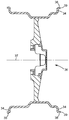
도 1은 본 발명에 따른 하나 이상의 접착제 배킹된 휠 밸런싱 웨이트를 장착하기에 적합한 차량 휠 림의 단면도이다.
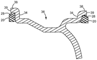
도 2는 차량 휠 림의 일부의 단면도로서, 그의 내부 및 외부 림 플랜지 상에
본 발명에 따른 휠 밸런싱 웨이트가 장착된다.
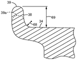
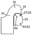
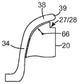
도 3은 2개의 가능한 플랜지 립 깊이(39, 39a)를 보여주는 차량 휠 림의 림 플랜지의 단면도로서, 깊이(69)를 갖는 림 플랜지 립(39)은 전형적으로 그 위에 종래의 클립-온(clip-on) 휠 웨이트를 수용하기 위하여 사용되고, 일정 깊이(약 3/16" 이하)를 갖는 림 플랜지 립(39a)(가상선으로 도시됨)은 전형적으로 장식을 목적으로 추가되고 그 위에 종래의 클립-온 휠 적용물을 수용하기에는 적합하지 않다.
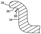
도 4a 내지 도 4d는 상이한 림 플랜지들의 단면도이다.
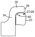
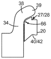
도 5a 내지 도 5g는 본 발명에 따른, 각각이 상이한 단부 프로파일을 갖는 휠 밸런싱 웨이트를 장착한 다양한 림 플랜지의 단면도이다.
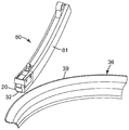
도 6은 일정 길이의 밸러스팅 웨이트(예를 들어, 휠 밸런싱 웨이트), 및 그러한 밸러스팅 웨이트를 기재의 표면 상의 원하는 위치에 보유, 배치 및/또는 부착하기 위한 장치의 일 실시예의 하부 사시도이다.
도 7은, 밸러스팅 웨이트가 장치의 조(jaw)들 사이에 부분적으로 보유된 상태의, 도 6의 장치 및 밸러스팅 웨이트 재료의 하부 사시도이다.
도 8은, 밸러스팅 웨이트가 장치의 조들 사이에 완전히 보유되고 이형 라이너가 그의 제거를 용이하게 하기 위하여 그가 보호하는 접착제를 지나서 연장되는 폭을 갖는, 도 6의 장치의 단부 사시도이다.
도 9는, 밸러스팅 웨이트를 차량 휠 림의 림 플랜지 상으로 적용하기 위하여 밸러스팅 웨이트가 그 내에 그리고 제위치에 완전히 보유되어 있는 상태의, 도 6의 장치의 하나의 조의 사시도이다.
도 10은 밸러스팅 웨이트를 림 플랜지의 플랜지 립에 인접하게 적용하기 위해 제위치에 있는 도 9의 장치의 조 및 밸러스팅 웨이트의 사시도이다.
도 11은 밸러스팅 웨이트가 플랜지 립에 인접하게 림 플랜지에 접착된 상태의, 도 9의 장치의 조 및 밸러스팅 웨이트의 단부 사시도이다.
도 12는 로봇 아암에 부착될 수 있는 본 발명에 따른 엔드 이펙터(end effector)의 평면도로서, 엔드 이펙터는 기재(예를 들어, 차량 휠 림의 림 플랜지)의 표면 상의 원하는 위치에 밸러스팅 웨이트를 보유, 배치 및/또는 부착하기 위한 장치를 포함하고, 그 내에 밸러스팅 웨이트가 부분적으로 삽입되어 있다.
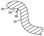
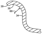
도 13은 차량 휠 림 플랜지의 플랜지 립에 인접하게 접착된 본 발명에 따른 휠 밸런싱 웨이트의 부분 단면 단부 사시도이다.
도 14a는, 어떠한 응력 완화 노치도 없는 상태에서, 3점 굽힘 시험에 의해 길이를 따라서 폭 방향으로 굽혀진, 본 발명에 따른 밸러스팅 웨이트의 전방 사시도이다.
도 14b는, 응력 완화 노치가 있는 상태에서, 3점 굽힘 시험에 의해 폭 방향으로 굽혀진 밸러스팅 웨이트의 전방 사시도이다.
도 14c는, 도 14b의 노치보다 더 깊은 응력 완화 노치가 있는 상태에서, 3점 굽힘 시험에 의해 길이를 따라서 폭 방향으로 굽혀진 밸러스팅 웨이트의 전방 사시도이다.
도 15a는 본 발명의 대안적인 실시예에 따른, 접착 테이프와 함께 연결된 복수의 개별 웨이트들을 포함하는 일정 길이의 밸러스팅 웨이트 재료의 평면도로서,
각각의 개별 웨이트는 금속(기본 또는 합금), 금속 입자 충전형 중합체 복합 재료 또는 다른 복합 재료이지만 (예를 들어, 도 6에 도시된 것과 같은) 본 발명에 따른 연속 밸러스팅 웨이트 재료 실시예와 동일한 유형의 또는 유사한 단부 프로파일 또는 단면을 갖는다.
도 15b는, 예를 들어 차량 휠 림의 곡률을 수용하도록 길이를 따라서 폭방향으로 굽혀진 도 15a의 밸러스팅 웨이트 재료의 평면도이다.
도 16a 내지 도 16d는 각각 본 발명에 따른 대안적인 밸러스팅 웨이트 단부 프로파일이다.
도 17a는 로봇 아암에 부착될 수 있는 본 발명에 따른 엔드 이펙터의 측면 사시도로서, 엔드 이펙터는 기재(예를 들어, 차량 휠 림의 림 플랜지)의 표면 상의 원하는 위치에 밸러스팅 웨이트를 보유, 배치 및/또는 부착하기 위한 대안적인 장치를 포함하고 있다.
도 17b는 도 17a의 엔드 이펙터의 하부 사시도이다.
도 18a는 대안적인 장치가 차량 휠 림의 림 플랜지 상의 원하는 위치에 대한 밸러스팅 웨이트의 부착을 개시하기 위해 제위치에 있는, 도 17a의 엔드 이펙터의 일부의 단부 사시도이다.
도 18b는 밸러스팅 웨이트의 일 단부가 초기에 차량 휠 림 플랜지에 부착된 지점으로부터 전체 밸러스팅 웨이트가 차량 휠 림 플랜지에 부착된 후에 제위치에 있는 도 18a의 엔드 이펙터 부분의 측면 사시도(가상선)로 천이되는 도 18a의 엔드 이펙터 부분의 단부 사시도이다.
도 18c는 도 18b의 원형 영역(18C)의 확대도이다.
도 18d는 밸러스팅 웨이트를 부착한 후에 차량 휠 림 플랜지로부터 먼 위치에 있는 도 18a의 엔드 이펙터 부분의 측면 사시도이다.In the accompanying drawings,
1 is a cross-sectional view of a vehicle wheel rim suitable for mounting one or more adhesive-backed wheel balancing weights in accordance with the present invention.
Figure 2 is a cross-sectional view of a portion of a vehicle wheel rim, on its internal and external rim flanges
A wheel balancing weight according to the present invention is mounted.
3 is a cross-sectional view of a rim flange of a vehicle wheel rim showing two possible
Figures 4A-4D are cross-sectional views of different rim flanges.
5A-5G are cross-sectional views of various rim flanges with wheel balancing weights, each having a different end profile, in accordance with the present invention.
6 is a bottom perspective view of an embodiment of a device for retaining, disposing and / or attaching a ballasting weight (e.g., a wheel balancing weight) of a certain length, and such a balancing weight at a desired location on the surface of the substrate.
Figure 7 is a bottom perspective view of the apparatus and ballasting weight material of Figure 6 with the ballasting weight partially retained between jaws of the apparatus.
Figure 8 is an end perspective view of the apparatus of Figure 6 with the ballasting weight fully retained between the sets of apparatus and having a width extending past the adhesive it protects to facilitate its removal.
Fig. 9 is a perspective view of one set of apparatus of Fig. 6 with the ballasting weight fully retained therein and in place to apply the ballasting weight to the rim flange of the vehicle wheel rim. Fig.
Figure 10 is a perspective view of the bar and ballasting weights of the apparatus of Figure 9 in place to apply the ballasting weight adjacent the flange lip of the rim flange.
11 is an end perspective view of the tubing and ballasting weight of the apparatus of FIG. 9 with the ballasting weight adhered to the flange lip adjacent to the flange lip.
Figure 12 is a plan view of an end effector according to the present invention that can be attached to a robot arm, wherein the end effector includes a balancing weight at a desired location on the surface of a substrate (e.g., a rim flange of the vehicle wheel rim) And / or attaching a ballasting weight to a ballasting weight within which a ballasting weight is partially inserted.
13 is a partial cross-sectional end perspective view of a wheel balancing weight according to the present invention adhered adjacent a flange lip of a vehicle wheel rim flange.
14A is a front perspective view of a ballasting weight according to the present invention, bent in the width direction along the length by a three-point bending test, without any stress relief notches.
14B is a front perspective view of a ballasting weight bent in a width direction by a three-point bending test in a state where there is a stress relief notch.
14C is a front perspective view of the ballasting weights bent in the width direction along the length by the three-point bending test, with a deeper stress relief notch than the notch of Fig. 14B. Fig.
15A is a plan view of a ballasting weight material of constant length comprising a plurality of individual weights coupled together with an adhesive tape, according to an alternative embodiment of the present invention,
Each individual weight may be a metal (a base or an alloy), a metal particle-filled polymer composite or other composite material, but may be the same as the continuous ballasting weight material embodiment according to the present invention (e.g., as shown in FIG. 6) Type or similar end profile or cross-section.
15B is a plan view of the ballasting weight material of FIG. 15A bent in the width direction along the length, for example, to accommodate the curvature of the vehicle wheel rim.
16A-16D are each an alternative ballasting weight end profile according to the present invention.
17A is a side perspective view of an end effector according to the present invention that can be attached to a robotic arm wherein the end effector has a ballasting weight at a desired location on the surface of a substrate (e.g., a rim flange of a vehicle wheel rim) And / or < / RTI >
Figure 17B is a bottom perspective view of the end effector of Figure 17A.
18A is an end perspective view of a portion of the end effector of FIG. 17A in which an alternative arrangement is in position to initiate attachment of a balancing weight to a desired location on a rim flange of a vehicle wheel rim.
18B is a side perspective view of the end effector portion of FIG. 18A in place after one end of the ballasting weight is initially attached to the vehicle wheel rim flange and the entire ballasting weight is attached to the vehicle wheel rim flange 18A. ≪ / RTI >
18C is an enlarged view of the circular area 18C in Fig. 18B.
18D is a side, perspective view of the end effector portion of FIG. 18A in a position remote from the vehicle wheel rim flange after attaching the ballasting weight.
본 발명의 실시예를 설명함에 있어서, 특정 용어가 명확함을 위해 사용된다. 그러나, 본 발명은 그와 같이 선택된 특정 용어로 제한되고자 하는 것은 아니며, 그와 같이 선택된 각각의 용어는 유사하게 작동하는 모든 기술적 등가물을 포함한다. 더욱이, 도면의 하기 상세한 설명이 휠을 밸런싱하기 위한 밸러스팅 웨이트의 사용과 관련되지만, 제공된 교시 내용이 본 발명에 따른 밸러스팅 웨이트의 어떠한 사용에도 동일하게 적용가능할 수 있다는 것으로 이해된다.In describing embodiments of the present invention, certain terminology is used for the sake of clarity. However, the invention is not intended to be limited to the specific terms so selected, and each term so selected includes all technical equivalents that work similarly. Moreover, although the following detailed description of the drawings relates to the use of balancing weights for balancing wheels, it is understood that the teachings provided may be equally applicable to any use of balancing weights in accordance with the present invention.
달리 지시되지 않는 한, 용어 "약"에 의해 변형되는 본 명세서 및 청구범위에 사용된 특징부 크기, 양 및 물리적 특성을 표현하는 모든 숫자는 본 명세서에 개시된 교시 내용을 이용하여 당업자들이 얻고자 하는 원하는 특성에 따라 달라질 수 있는 근사치이다.Unless otherwise indicated, all numbers expressing feature sizes, amounts, and physical characteristics used in this specification and claims that are modified by the term " about " are intended to be within the scope of one of ordinary skill in the art It is an approximation that can vary depending on the desired characteristics.
종점들에 의한 수치 범위의 언급은 그 범위 내에 포함되는 모든 수를 포함하며(예를 들어, 1 내지 5는 1, 1.5, 2, 2.75, 3, 3.80, 4 및 5를 포함함), 그 범위 내의 임의의 범위를 포함한다.References to numerical ranges by endpoints include all numbers contained within that range (e.g., 1 to 5 include 1, 1.5, 2, 2.75, 3, 3.80, 4, and 5) Lt; / RTI >
본 명세서 및 첨부된 청구범위에 사용된 바와 같이, 단수 형태("a", "an" 및 "the")는, 그 내용이 명백히 달리 지시하지 않는 한, 복수의 지시 대상을 갖는 실시예를 포괄한다. 본 명세서 및 첨부된 청구범위에 사용되는 바와 같이, 용어 "또는"은 일반적으로, 그 내용이 명백히 달리 지시하지 않는 한, 그의 의미에 있어서 "및/또는"을 포함하는 것으로 사용된다.As used in this specification and the appended claims, the singular forms "a," "an," and "the" include, unless the context clearly indicates otherwise, do. As used in this specification and the appended claims, the term "or" is generally used to include "and / or" in its sense of meaning unless the context clearly dictates otherwise.
용어 "중합체"는 중합체, 공중합체(예를 들어, 2개 이상의 상이한 단량체들을 사용하여 형성된 중합체), 올리고머 및 이들의 조합뿐만 아니라 혼화 가능한 블렌드로 형성될 수 있는 중합체, 올리고머 또는 공중합체를 포함하는 것으로 이해될 것이다.The term "polymer" includes polymers, oligomers or copolymers that can be formed into polymers, copolymers (e.g., polymers formed using two or more different monomers), oligomers and combinations thereof, as well as miscible blends .
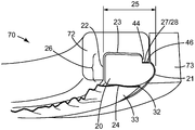
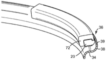
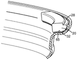
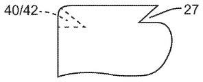
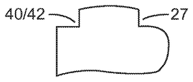
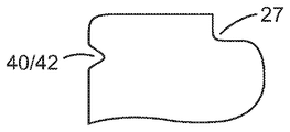
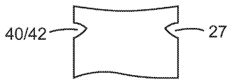
본 발명에 따른 밸러스팅 웨이트의 예는 자동차에서 종래에 사용되는 것과 같은 휠을 밸런싱하기 위한 밸런싱 웨이트(20)이다. 도 1, 도 2, 도 5, 도 11, 도 13, 및 도 18d를 참조하면, 그러한 웨이트(20)는 휠 림(36)의 림 플랜지(34) 상에 장착될 수 있다. 밸런싱 웨이트(20)는 밸런싱을 위한 원하는 질량을 제공하는 길이, 폭(25), 두께(26), 제1 선단(leading) 또는 정지 면(21), 제2 면(22), 상부(23), 및 하부(24)를 갖는데, 이때 단면 또는 단부 프로파일은 밸런싱 웨이트(20)의 제1 면(21)의 길이를 따라서 종방향으로 연장된 홈(28)을 형성하는 제1 또는 선단 노치(27)를 포함한다. 도 5c, 도 5d, 도 5f, 및 도 16을 참조하면, 밸런싱 웨이트(20)의 단면 프로파일은 또한 밸런싱 웨이트(20)의 제2 면(22)의 길이를 따라서 종방향으로 연장된 다른 홈(42)을 형성하는 제2 또는 후단(trailing) 노치(40)를 포함할 수 있다. 그러한 밸런싱 웨이트들(20)의 예시적인 단부 프로파일들이 도 2, 도 5, 도 8, 및 도 16에 도시되어 있다. 밸런싱 웨이트(20)는, 예를 들어, 층 또는 테이프(32)와 같은 접착제에 의해 배킹될 수 있다. 밸런싱 웨이트(20)가 접착제(32)로 배킹된 경우, 이형 라이너(33)가 접착제 표면을 보호하기 위하여 사용될 수 있다. 접착 테이프(32)는 접착 테이프(32)의 일 면이 밸런싱 웨이트(20)의 하부 만곡 표면(24)에 접착되어 있는 양면 접착 테이프(32)일 수 있다.An example of a balancing weight according to the present invention is a balancing
접착제(32)는 밸런싱 웨이트(20)의 제1 면(21)으로부터 뒤로 이격된 선단 에지를 갖는 것이 바람직하다. 접착제(32)는, 예를 들어, 도 5a 내지 도 5g에 도시된 것과 같이, 휠 밸런싱 웨이트(20)의 제1 면(21)과 플랜지 립(38)의 만곡부(68) 사이에 어떠한 접착제(32)도 위치되지 않도록 휠 밸런싱 웨이트(20)의 하부(24)에 접착되는 것이 바람직할 수 있다. 휠 밸런싱 웨이트(20)는, 휠 밸런싱 웨이트(20)의 제1 면(21)이 영(0)에서부터 접착제(32)의 두께(26)의 약 2배까지 그리고 그를 포함하는 범위의 플랜지 립(38)으로부터의 거리에 위치되도록, 휠 림(36)의 림 플랜지(34)에, 접착제(32)에 의해, 접착되는 것이 바람직할 수 있다. 휠 밸런싱 웨이트(20)는 휠 밸런싱 웨이트(20)의 제1 면(21)과 플랜지 립(38) 사이에 갭(gap)이 존재하도록 - 접착제(32)는 영(0)에서부터 갭의 체적의 약 25%까지 그리고 그를 포함하는 범위로 충전됨 - 휠 림(36)의 림 플랜지(34)에 접착되는 것이 또한 바람직할 수 있다.The adhesive 32 preferably has a leading edge that is spaced back from the
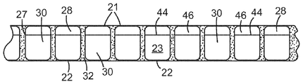
각각의 노치(27 및/또는 40)는 서로 반대편인 레그(leg)들을 포함하고, 밸런싱 웨이트(20)의 상부(23)와 하부(24) 사이에 위치된다. 이들 서로 반대편인 레그들 중 하나는 그의 대응하는 면(21, 22)으로부터 연장된 하부 레그일 수 있고, 서로 반대편인 레그들 중 다른 하나는 하부 레그로부터 상부(23)를 향하여 연장된 측부 레그일 수 있다. 측부 레그는 단면 프로파일의 제2 면(22)에 평행한 것이, 요구되지는 않지만, 바람직할 수 있다. 유사하게, 각각의 홈(28, 42)은 서로 반대편인 표면들을 포함할 수 있는데, 서로 반대편인 표면들 중 하나는 하부 표면(46)이고, 서로 반대편인 표면들 중 다른 하나는 측부 표면(44)이고, 서로 반대편인 표면들은 이들 사이에 각(예를 들어, 직각)을 형성한다. 밸런싱 웨이트(20)는 상부(23), 제2 면(22), 홈 하부 표면(46), 및 홈 측부 표면(44) 중 적어도 하나 상에 평탄한 표면을 포함할 수 있다. 홈(28 및/또는 42)의 하부 표면(46)은 밸런싱 웨이트(20)의 상부(23) 상의 표면에 평행할 수 있고, 홈(28 및/또는 42)의 측부 표면(44)은 밸런싱 웨이트(20)의 제2 면(22) 상의 표면에 평행할 수 있다. 각각의 홈(28 및/또는 42)의 서로 반대편인 표면들(44, 46) 및 각각의 노치(27 및/또는 40)의 서로 반대편인 레그들은 약 45도에서부터 약 135도까지 그리고 약 135도를 포함하는 범위의 각만큼 분리되는 것이 바람직할 수 있다. 적어도 하나의 노치(27 및/또는 40)는 "V-형상" 노치인 것이 바람직할 수 있는데, 이때 대응하는 홈(28, 42)이 웨이트(20)의 면(21 및/또는 22)으로부터 외부로 개방되어 있다.Each
각각의 홈(28 및/또는 42)은 밸런싱 웨이트(20)의 자동 분배 및/또는 적용을 용이하게 하기 위하여 작동식으로 적응(즉, 치수설정, 설계 또는 달리 구성)되는 것이 바람직하다. 예를 들어, 각각의 홈(28 및/또는 42)은 장치(70 또는 80)의 일부를 내부에 수용하기 위해 작동식으로 적응될 수 있는데, 여기서 장치(70 또는 80)는 밸런싱 웨이트(20)를 보유하도록 작동식으로 적응된 구조를 포함하여서, 장치(70 또는 80)가 밸런싱 웨이트(20)를 원하는 위치에 배치할 수 있고 밸런싱 웨이트(20)를 원하는 표면 상으로 가압할 수 있도록 한다. 그러한 장치(70, 80)는 아래에서 더 상세히 설명된다.Each
도 6 내지 도 11, 도 17 및 도 18을 참조하면, 장치(70, 80)는 밸런싱 웨이트(20)를 보유하도록 작동식으로 적응(즉, 치수설정, 설계 또는 달리 구성)된 구조를 포함하여서, 장치(70, 80)가 휠 림(36)의 원하는 표면 또는 다른 기재 표면에 인접한 원하는 위치에 위치될 수 있도록, 그리고 장치(70, 80)가 밸런싱 웨이트(20)를 조작하여 밸런싱 웨이트(20)를 표면(예를 들어, 표면(65))에 부착하도록 하는 것이 바람직하다. 특히, 장치(70, 80)는 주연 에지(39)를 구비한 플랜지 립(38)을 갖는 림 플랜지(34)를 포함하는 휠 림(36)에 인접한 원하는 위치에 위치될 수 있고, 장치(70, 80)는 휠 밸런싱 웨이트(20)를 림 플랜지(34)의 표면(65)에 그리고 플랜지 립(38)에 인접하게 부착시키도록 휠 밸런싱 웨이트(20)를 조작할 수 있다. 도 13을 참조하면, 웨이트 하부(24)의 표면의 토포그래피(topography)는 접착제(32)에 의한 표면(65)과 웨이트 하부(24) 사이의 우수함 접합을 잘 보장하기 위하여 림 플랜지 표면(65)의 토포그래피와 동일한 것이 바람직할 수 있다.Referring to Figures 6-11, 17 and 18, the
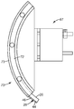
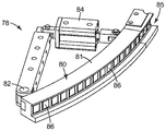
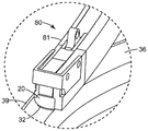
예를 들어, 장치(70)는 제1 아치형 조(72) 및 제2 아치형 조(73)를 포함하고, 이는 도 6 내지 도 12에 도시된 것과 같이 이들 사이에 일정 곡률 반경을 갖고 길이를 따라서 폭 방향으로 굽혀진 밸런싱 웨이트(20)를 그렇게 보유하도록 작동식으로 적응된다. 도 9 내지 도 12를 참조하면, 장치(70)는, 회전 축(37) 및 회전 축(37)을 중심으로 하는 곡률 반경을 갖는 휠 림(36)의 곡률 반경과 매칭하는 폭 방향 곡률 반경을 갖도록 밸런싱 웨이트(20)를 폭 방향으로 굽힘으로써, 휠 림(36)의 림 플랜지(34) 상에 휠 밸런싱 웨이트(20)를 장착하는 데 사용될 수 있다. 그에 반하여, 장치(80)는 제1 아치형 조(81) 및 매칭하는 제2 아치형 조(미도시)를 포함하고, 이는 도 18a 내지 도 18d에 도시된 것과 같이 이들 사이에 일정 곡률 반경을 갖고 두께 방향으로 굽혀진 밸런싱 웨이트(20)를 그렇게 보유하도록 작동식으로 적응된다. 이러한 방식으로, 장치(80)는, 밸런싱 웨이트(20)를 그의 두께 방향으로 굽힘으로써, 휠 림(36)의 곡률 반경과 관계없이(즉, 휠 림의 곡률 반경과 매칭할 필요 없이), 휠 밸런싱 웨이트(20)를 임의의 휠 림 플랜지(34) 상에 장착하는 데 사용될 수 있다.For example, the
도 18a 내지 도 18d에 도시된 바와 같이, 장치(80)는, 웨이트(20)의 일 단부에서의 접착제(32)가 플랜지 표면(65)에 접착될 때까지 적어도 조(81)의 대응하는 단부를 플랜지(34)를 향하여 이동시킴으로써, 웨이트(20)의 일 단부가 에지(39)에 인접한 휠 림 플랜지(34)에 초기에 고정되게 한다. 웨이트(20)의 잔여 길이는, 조(81)를 플랜지(34)로부터 멀리 이동시키지 않고, 휠 림(36)의 아크, 이어서 에지(39) 둘레로 조(81)를 이동시킴으로써 플랜지 표면(65)에 고정된다. 이러한 방식으로, 초기에는 표면(65)에 접착되지 않은 웨이트(20)의 잔여 길이가 장치(80) 외부로 당겨져서 표면(65)의 대응하는 부분에 접착된다.18A-18D, the
장치(70, 80)의 조들은 휠 밸런싱 웨이트(20)를 내부에 수용하기 위한 채널(74, 85)을 각각 형성한다. 장치(70, 80)는, 밸런싱 웨이트(20)가 초기에 대응하는 채널(74,85) 내로 삽입되는 경우, 장치의 조들을 서로를 향하여 편의(bias)시키기 위한 메커니즘(미도시)을 포함할 수 있다. 이러한 메커니즘은, 웨이트(20)가 적용되기 전에, 밸런싱 웨이트(20)를 조들 사이에 보유하기 위하여 조들이 서로를 향하여 편의되게 유지시키는 것이 바람직할 수 있다. 조들은 밸런싱 웨이트(20)가 표면에 부착된 이후를 포함하여 밸런싱 웨이트(20)가 조들 내에 위치된 이후에는 언제든 서로로부터 멀어지게 편의될 수 있다. 웨이트(20)를 제1 조(72) 상에 보유하는 것을 적어도 돕기 위하여, 제2 조(73)가 후퇴되는 경우, 장치(70)는 자석을 수용하기 위한 막힌 구멍 및/또는 관통 구멍으로서 형성된, 또는 진공이 웨이트(20)를 끌어당길 수 있게 하는 관통 구멍으로서 형성된 구멍(76)을 포함할 수 있다. 유사하게, 장치(80)는, 웨이트(20)를 제1 조(81) 상에 보유하는 것을 적어도 돕기 위하여, 자석을 수용하기 위한 막힌 구멍 및/또는 관통 구멍으로서 형성된, 또는 진공이 웨이트(20)를 끌어당길 수 있게 하는 관통 구멍으로서 형성된 구멍(86)을 포함할 수 있다.The sets of
장치(70)의 제1 아치형 조(72)는 내부에 밸런싱 웨이트(20)의 제2 면(22)의 적어도 일부 및 상부(23)를 수용하도록 작동식으로 적응되고, 제2 아치형 조(73)는 내부에 밸런싱 웨이트(20)의 제1 면(21)의 적어도 일부를 수용하도록 작동식으로 적응된다. 제2 면(22)의 적어도 일부 및 상부(23)를 내부에 수용하는 것에 더하여, 제1 아치형 조(72)는 또한 휠 밸런싱 웨이트(20)의 적어도 하나의 홈(28 및/또는 42)의 적어도 일부를 수용할 수 있다. 장치(80)의 조들은 유사하게 적응된다.The first
도 8 내지 도 11을 참조하면, 적어도 하나의 홈(28 및/또는 42)의 측부 표면(44)은 보유 표면일 수 있는데, 웨이트(20)가 제위치에 있거나 또는 그와 달리 휠 림(36)의 표면에 접착될 준비가 되어 있을 때까지, 장치(70)는 장치(70) 내에 밸런싱 웨이트(20)를 보유하도록 보유 표면에 대항하여 파지력을 인가한다. 이러한 파지력은 밸런싱 웨이트(20)의 적어도 하나의 홈(28 및/또는 42)의 측부 표면(44)과 그의 반대 면(22 및/또는 21) 사이에 인가될 수 있다. 예를 들어, 파지력은 웨이트(20)의 홈(28)의 적어도 측부 표면(44) 또는 양 표면(44, 46)과 그의 반대 면(22) 사이에 인가될 수 있다. 추가적으로 또는 대안적으로, 파지력은 웨이트(20)의 홈(42)의 적어도 측부 표면(44) 또는 양 표면(44, 46)과 그의 반대 면(21) 사이에 인가될 수 있다. 파지력은 하나의 홈(28)의 적어도 측부 표면(44)과 다른 홈(42)의 적어도 측부 표면(44) 사이에 인가될 수 있다. 각각의 홈(28 및/또는 42)의 하부 표면(46)은 또한 가압 표면으로서 기능할 수 있는데, 장치(70)는, 예를 들어 림 플랜지 표면(65)과 같은 표면에 대항하여 밸런싱 웨이트(20)를 가압하도록 가압 표면에 대항하여 힘을 전달할 수 있다.8-11, the
장치(70 또는 80)가 휠 림(36)의 림 플랜지(34) 또는 다른 부분과 간섭하지 않고서 (예컨대, 그와 이른 접촉을 이루지 않고서), 홈(28)이 웨이트(20)가 휠 림(36)의 림 플랜지(34) 또는 다른 부분에 접착되게 하는 경우에 밸런싱 웨이트(20)의 자동 분배 및/또는 적용이 용이해질 수 있어서, 그에 의해 웨이트(20)가 휠 림(36)의 원하는 표면에 접착식으로 접합되는 것을 방지 또는 그와 달리 방해한다. 예를 들어, 도 11을 참조하면, 홈(28)은, 접착제(32)가 림 플랜지 표면(65)에 접착되는 경우, 장치(70)의 일부(예를 들어, 장치의 조(72))가 휠 림 플랜지(34)의 주연 에지(39)와 접촉하지 않도록 구성된다. 장치(80)의 조(81)는 유사하게 구성된다.The
도 12 및 도 17에 도시된 바와 같이, 장치(70, 80)는 로봇 아암(미도시)에 부착될 수 있는 엔드 이펙터(67 또는 78)의 선단부를 형성할 수 있다. 이어서, 각각의 엔드 이펙터(67, 78)는 차량 휠 림(36)의 림 플랜지(34)의 표면 또는 다른 기재 표면 상의 원하는 위치에 밸러스팅 웨이트(20)를 수동으로 또는 자동으로 보유, 배치 및/또는 부착하는 데 사용될 수 있다. 도 12에 도시된 엔드 이펙터(67)는, 그가 부착되는 로봇 아암(미도시)을 이동시킴으로써 변화가능한 고정된 배향으로 장치(7)를, 그리고 그에 따른 웨이트(20)를 보유한다. 그에 반하여, 도 17에 도시된 다른 엔드 이펙터는, 조(81)(즉, 웨이트(20))의 타 단부가 예를 들어 공압 또는 전기 피스톤과 같은 액추에이터 메커니즘(84)에 의해 이동되는 경우, 장치(80)가, 그리고 그에 따른 웨이트(20)가 조(81)의 일 단부에서 지점(82)을 중심으로 선회하게 한다. 라이너(33)는 웨이트(20)가 사용되고 있는 장치(70, 80)의 채널(74,85) 내로 공급되기 전에, 그 동안 또는 그 후에 접착제(32)로부터 제거될 수 있다.As shown in FIGS. 12 and 17, the
밸런싱 웨이트(20)는 넓기보다는 더 길 수 있고 두껍기보다는 더 넓을 수 있으며, 이때 폭(25) 대 두께(26) 비(W/T)는 적어도 약 1.0에서부터 0.1의 증분으로 약 2.3 미만까지의 범위에 있어서, 밸런싱 웨이트(20)가 그의 길이를 따라서 폭 방향으로 용이하게 굽혀질 수 있게 한다. 그러한 웨이트 구성은 장치(70)와 함께 사용되는 경우 특히 바람직할 수 있다. 장치(80)의 사용은 더욱 더 높은 W/T 비의 사용을 허용할 수 있다. 밸런싱 웨이트(20)는 넓기보다는 더 길 수 있고 두껍기보다는 더 넓을 수 있다. 휠 밸런싱 웨이트(20)의 두께(26)는 약 47.625 mm 이하인 것이 바람직할 수 있다. 웨이트(20)의 하부(24)는, 표면(65)과 같은 휠 림(36)의 대응하는 표면과 매칭하거나 또는 그와 달리 그에 견고하게 접합되도록 제1 면(21)과 제2 면(22) 사이에서 만곡된 표면을 가질 수 있다.The balancing
밸런싱 웨이트(20)는 도 15a 및 도 15b에 도시된 것들과 같이 하나 또는 다수의 개별 웨이트들(20) 및/또는 웨이트들(30)을 포함할 수 있다. 휠 밸런싱 산업에서, 개별 웨이트(30)는 종종 치클릿으로 지칭된다. 각각의 휠 밸런싱 웨이트(20, 30)는 종래의 클립-온 납 휠 밸런싱 웨이트의 선밀도보다 크거나, 그와 동일하거나, 또는 그보다 작은 선밀도를 가질 수 있다. 각각의 휠 밸런싱 웨이트(20)가 다수의 개별 웨이트들(20 및/또는 30)을 포함하는 경우, 접착제(32)는 테이프인 것이 바람직할 수 있는데, 이때 개별 웨이트들(20 및/또는 30)이 접착 테이프(32)에 의해 배킹되고 서로 연결된다. 일정 길이의 밸런싱 웨이트 재료가 복수의 밸런싱 웨이트(20 또는 30)로 분리가능한 것이 바람직할 수 있다. 그러한 일정 길이의 밸런싱 재료는, 예를 들어, 레벨 권취형 스풀(level wound spool)과 같은, 재료의 스풀로 권취될 수 있다. 각각의 밸런싱 웨이트(20)는 하나 또는 다수의 개별 웨이트(20 및/또는 30)를 포함할 수 있다.Balancing
도 14a 내지 도 14c를 참조하면, 밸런싱 웨이트(20)는 그의 길이를 따라서 길이 방향으로 이격된 복수의 또는 적어도 하나의 응력 완화 노치들 또는 절개부들(64)을 포함할 수 있는데, 이때 폭(25)이 두께(26)보다 더 크거나 또는 두께(26)가 폭(25)보다 더 크다. 각각의 응력 완화 노치(64)는 밸런싱 웨이트(20)를 응력 완화 노치들(64)의 방향으로 굽히는 데 더 적은 힘이 필요하도록 단지 부분적으로 밸런싱 웨이트(20)를 통하여 형성된다. 밸런싱 웨이트(20)가 두껍기보다는 더 넓은 경우, 각각의 응력 완화 노치(64)는, 더 적은 힘이 응력 완화 노치들(64)의 방향으로 밸런싱 웨이트(20)를 폭 방향으로 굽히는 데 필요하도록, 두께(26)를 통하여 그리고 부분적으로 폭(25)을 통하여 제1 면(21)으로부터 제2 면(22)을 향하여 형성되는 것이 바람직할 수 있다. 접착제 층 또는 테이프(32)가 밸런싱 웨이트(20)의 하부(24)에 부착되는 경우, 각각의 응력 완화 노치(64)는 접착제(32)를 절단하지 않도록 형성될 수 있다.14A-14C, the balancing
밸런싱 웨이트(20)의 면(21)은, 휠 림(36)의 회전에 의해 야기되는 원심력이 부착된 휠 밸런싱 웨이트(20)에 인가되는 경우, 림 플랜지(34)의 플랜지 립(38)에 의해 정지되도록 작동식으로 적응되는 정지 표면을 포함할 수 있다. 밸런싱 웨이트(20)는 휠 밸런싱 웨이트(20)가 휠 림 플랜지(34)로부터 떨어지도록 플랜지 립(38)의 주연 에지(39) 위로 충분히 연장되게 할만큼 두껍지 않은 것이 바람직하다. 예를 들어, 휠 밸런싱 웨이트(20)는, 휠 림 플랜지(34)에 접착되는 경우, 플랜지 립(38)의 주연 에지(39) 위로 연장되지 않을 정도로 충분히 얇을 수 있다. 도 3을 참조하면, 플랜지 립(38)의 주연 에지(39)는, 종래의 클립-온 휠 밸런싱 웨이트를 수용하기에 적합하도록, 웨이트(20)가 접착되는 림 플랜지(34)의 표면 위로 충분히 연장된 깊이(69)를 가질 수 있다. 종래의 클립-온 휠 웨이트를 수용하기에 적합하지 않지만 웨이트(20)가 그러한 원심력의 결과로서 떨어지는 것을 립(38)이 중지시킬 수 있도록 여전히 충분히 깊은 깊이(69)를 갖는, 가상선으로 도시된 주연 에지(39a)가 또한 존재할 수 있다. 휠 밸런싱 웨이트(20)의 선단 면(21) 상의 정지 표면은, 휠 밸런싱 웨이트(20)가 (a) 폭 방향으로(도 9 내지 도 12에 도시된 바와 같음) 또는 (b) 두께 방향으로(도 18a 내지 도 18d에 도시된 바와 같음) 굽혀지고 플랜지 립(38)의 제2 곡률 반경(68) 내에 배치되는 경우, 림 플랜지(34)의 플랜지 립(38)의 제2 곡률 반경(68)과 일치하도록 작동식으로 적응(즉, 치수설정, 설계 또는 달리 구성)된 두께(26) 방향으로의 제1 곡률 반경(66)을 가질 수 있다. 도 5a 내지 도 5g에 도시된 바와 같이, 휠 밸런싱 웨이트(20)의 제1 곡률 반경(66)은 플랜지 립(38)의 제2 곡률 반경(68)과 동일할 수 있다.The
시험 방법Test Methods
3점 굽힘 시험3 point bending test
밸러스팅 웨이트가 접합되거나 또는 그와 달리 부착되는 만곡 표면과 일치하도록 밸러스팅 웨이트의 강성을 감소시키고 그의 굽힘을 더 용이하게 하기 위하여, 응력 완화 노치들 또는 절개부들이 굽힘 방향으로 (예를 들어, 폭 방향으로) 밸러스팅 웨이트에 형성되어 밸러스팅 웨이트 재료의 모듈러스(modulus)를 감소시킬 수 있다. 도 14a, 도 14b 및 도 14c를 참조하면, 3개의 예시적인 휠 밸런싱 웨이트 샘플에 대해 3점 굽힘 시험을 행함으로써 그러한 응력 완화 구조를 사용한 유효성을 시험하였다. 하나의 샘플이 완화 절개부가 없었고(도 14a 참조), 두 번째 샘플이 깊이가 4 mm인 6개의 동일하게 이격된 완화 절개부를 가졌고(도 14b 참조), 그리고 세 번째 샘플이 절개부의 깊이가 9 mm인 것 외에는 제2 샘플과 동일하였다(도 14c 참조)는 것을 제외하고는 3개의 모든 샘플들이 동일하였다. 첫 번째 샘플(절개부 없음)은 휠 밸런싱 웨이트를 적절하게 굽히기 위하여 29.0 N의 힘이 필요하였다. 두 번째 샘플(4 mm 깊이의 절개부)은 휠 밸런싱 웨이트를 적절하게 굽히기 위하여 17.9 N의 힘이 필요하였다. 세 번째 샘플(9 mm 깊이의 절개부)은 휠 밸런싱 웨이트를 적절하게 굽히기 위하여 9.8 N의 힘만이 필요하였다. 4 mm 완화 절개부들은 굽힘 하중을 적절히 감소시켰고 휠 밸런싱 웨이트의 하부면 상의 접착 테이프를 절단하지 않았다. 완화 절개부들은 원하는 증분값(예를 들어, ¼ 온즈 또는 5 그램의 증분값)으로 배치되어 시각적 웨이트 결정법을 제공할 수 있다.In order to reduce the stiffness of the balancing weights so as to conform to the curved surface to which the balancing weights are joined or otherwise attached, and to make it easier to bend, the stress relief notches or cuts are formed in the bending direction (e.g., In the width direction) to reduce the modulus of the ballasting weight material. Referring to Figs. 14A, 14B and 14C, three-point bending tests were performed on three exemplary wheel balancing weight samples to test their effectiveness using such stress relieving structures. 14A), and the second sample had six equally spaced relaxed incisions with a depth of 4 mm (see FIG. 14B), and the third sample had an incision depth of 9 mm (See Fig. 14C) except that the second sample was the same as the second sample. The first sample (no incision) required a force of 29.0 N to properly bend the wheel balancing weight. The second sample (incision at 4 mm depth) required a force of 17.9 N to properly bend the wheel balancing weight. The third sample (incision at 9 mm depth) required only 9.8 N of force to properly bend the wheel balancing weight. The 4 mm relief cuts suitably reduced the bending load and did not cut the adhesive tape on the lower surface of the wheel balancing weight. The mitigation incisions can be placed at the desired incremental value (e.g., an increment of ¼ ounces or 5 grams) to provide a visual weight determination method.
회전(spin) 시험Spin test
종래의 자동차 휠로부터의 강철 림의 림 플랜지를 이용하여 시험 고정구(fixture) 상에 아크릴 발포 접착 테이프로 접합된 도 11에 도시된 것과 같은 단면 프로파일을 갖는 15 그램의 휠 밸런싱 웨이트 샘플들을 사용하여 회전 시험을 수행하였다. 생성된 고정된 휠 밸런싱 웨이트들을, 14 인치 휠 림에 대해 20,000 마일 초과의 주행에 대응하는 8660분(6일) 동안 온도(100℉) 및 습도(95% RH) 제어식 챔버 내에서 1700 rpm(140 mph)으로 회전시켰다. 어떠한 샘플도 휠 림 고정구로부터 분리되어 달아나지 않았다.Using 15 gram of wheel balancing weight samples with a cross-sectional profile as shown in Fig. 11 bonded to an acrylic foam adhesive tape on a test fixture using a rim flange of a steel rim from a conventional automotive wheel, The test was performed. The resulting fixed wheel balancing weights were measured at 1700 rpm (140 [deg.] F) in a controlled chamber (100 [deg.] F) and humidity (95% RH) for 8660 minutes (6 days) mph). No samples were detached from the wheel rim fixture.
다양한 실시예Various embodiments
밸러스팅 웨이트의 실시예Example of Balusting Weight
1. 길이, 폭, 두께, 제1 선단(예를 들어, 이는, 예컨대, 휠이 회전하는 경우 휠 밸런싱 웨이트에 인가된 원심력과 같은, 인가된 힘에 의해 야기되는 운동의 방향으로 선단에 있는 면이다) 또는 정지 면(예를 들어, 이는 휠 밸런싱 웨이트의 이동을 정지시키기 위하여 회전하는 휠의 림 플랜지와 접촉을 이루는 표면을 갖는 면이다), 반대편인 제2 면, 상부, 및 하부, 외부 표면, 그리고 단면 프로파일을 갖는 밸러스팅(예를 들어, 휠 밸런싱) 웨이트로서, 단면 프로파일은 밸러스팅 웨이트의 제1 면의 길이를 따라서 종방향으로 연장된 홈을 형성하는 적어도 하나의 노치를 포함하고, 홈은 밸러스팅 웨이트의 자동 분배 및 적용을 용이하게 하도록 작동식으로 적응(즉, 치수설정, 설계 또는 달리 구성)되고, 밸러스팅 웨이트는 하나 또는 다수의 개별 웨이트들을 포함할 수 있는, 밸러스팅 웨이트. 각각의 홈의 기하학적 형상은 공구 또는 다른 장치가 밸러스팅 웨이트(예를 들어, 접착제 배킹된 휠 밸런싱 웨이트)를 기재(예를 들어, 휠 림)의 원하는 위치 표면 상으로 (예를 들어, 림 플랜지의 플랜지 립에 인접한 휠 림의 림 플랜지 상으로) 파지, 배치 및 가압하게 하도록 구성된다.One. (E.g., it is a face at the leading end in the direction of movement caused by an applied force, such as, for example, the centrifugal force applied to the wheel balancing weight when the wheel rotates) Or a stop surface (e.g., a surface having a surface that makes contact with a rim flange of a rotating wheel to stop movement of the wheel balancing weight), a second side opposite, a top and bottom, an outer surface, and A ballasting (e.g., wheel balancing) weight having a cross-sectional profile, wherein the cross-sectional profile includes at least one notch defining a longitudinally extending groove along the length of the first surface of the ballasting weight, (I. E., Dimensioned, designed or otherwise configured) to facilitate automatic dispensing and application of ballasting weights, and the ballasting weights include one or more individual weights Wed, ballasting weights in. The geometry of each groove may be such that a tool or other device is positioned on a desired location surface of the substrate (e.g., a wheel rim) (e.g., a rim flange On the rim flange of the wheel rim adjacent to the flange lip of the wheel rim).
2. 실시예 1에 있어서, 밸러스팅 웨이트의 단면 프로파일은 밸러스팅 웨이트의 제2 면의 길이를 따라서 종방향으로 연장된 다른 홈을 형성하는 다른 노치를 포함하고, 다른 홈은 밸러스팅 웨이트의 자동 분배 및 적용을 용이하게 하도록 작동식으로 적응(즉, 치수설정, 설계 또는 달리 구성)된, 밸러스팅 웨이트.2. The cross sectional profile of the balancing weights in Example 1 includes another notch that forms another groove extending longitudinally along the length of the second face of the balancing weights and the other groove comprises an automatic dispensing of balancing weights A ballasting weight that is actively adapted (ie, dimensioned, designed or otherwise configured) to facilitate application.
3.
실시예 1 또는 실시예 2에 있어서, 각각의 홈은 서로 반대편인 표면들을 포함하고, 서로 반대편인 표면들 중 하나는 하부 표면(예를 들어, 도 11에서 예시된 바와 같은 대체적으로 수평인 표면)이고, 서로 반대편인 표면들 중 다른 하나는 측부 표면(예를 들어, 도 11에서 예시된 바와 같은 대체적으로 수직인 표면)이며, 서로 반대편인 표면들은 이들 사이에 직각을 형성하는, 밸러스팅 웨이트. 본 명세서에서 사용되는 바와 같이, 용어 직각은 정확하게 90도, 90도보다 약간 작은, 또는 90도보다 약간 큰 각(예를 들어, 90도 + 최대 15도 또는 90도 - 최대 15도 범위의 임의의 각)을 지칭한다.3.
In
4. 실시예 1 내지 실시예 3 중 어느 한 실시예에 있어서, 홈의 하부 표면은 밸러스팅 웨이트의 상부 상의 표면에 평행하고, 홈의 측부 표면은 밸러스팅 웨이트의 제2 면 상의 표면에 평행한, 밸러스팅 웨이트. 본 명세서에서 사용되는 바와 같이, 2개의 표면들은 이들이 정확하게 평행하거나 또는 정확히 평행한 것에 15도 이내로 평행한 경우에 평행한 것으로 여겨진다.4. The bottom surface of the groove is parallel to the surface on the top of the ballasting weight and the side surface of the groove is parallel to the surface on the second side of the ballasting weight, Ting weight. As used herein, two surfaces are considered to be parallel when they are parallel to exactly parallel or less than 15 degrees to exactly parallel.
5. 실시예 1 내지 실시예 4 중 어느 한 실시예에 있어서, 단면 프로파일은 상부, 제1 면 및 제2 면을 포함하고, 적어도 하나의 노치는 서로 반대편인 레그들을 포함하고, 서로 반대편인 레그들 중 하나는 하부 레그(예를 들어, 도 11에 예시된 바와 같은 대체적으로 수평인 레그)이고, 서로 반대편인 레그들 중 다른 하나는 하부 레그로부터 상부를 향하여 연장된 측부 레그(예를 들어, 도 11에 예시된 바와 같은 대체적으로 수직인 레그)인, 밸러스팅 웨이트. 측부 레그가 단면 프로파일의 제2 면에 평행한 것이, 요구되지는 않지만, 바람직할 수 있고, 서로 반대편인 레그들은 이들 사이에 직각을 형성하는 것이 바람직할 수 있다. 본 명세서에서 사용되는 바와 같이, 용어 직각은 정확하게 90도, 90도보다 약간 작은, 또는 90도보다 약간 큰 각(예를 들어, 90도 + 최대 15도 또는 90도 - 최대 15도 범위의 임의의 각)을 지칭한다. 본 명세서에서 사용되는 바와 같이, 단면 프로파일의 2개의 레그들 또는 섹션들은 이들이 정확하게 평행하거나 또는 정확히 평행한 것에 15도 이내로 평행한 경우에 평행한 것으로 여겨진다.5. [0042] [0053] In any one of embodiments 1-4, the cross-sectional profile includes an upper, a first side, and a second side, wherein at least one notch comprises legs opposite to each other, One of which is a lower leg (e.g., a generally horizontal leg as illustrated in FIG. 11), and the other of the opposite legs is a side leg extending upwardly from the lower leg (e.g., Generally vertical leg as illustrated in Fig. It may be desirable, but not required, that the side legs be parallel to the second side of the cross-sectional profile, and legs opposite to each other may be preferred to form a right angle therebetween. As used herein, the term orthogonality refers to an angle that is precisely 90 degrees, slightly less than 90 degrees, or slightly greater than 90 degrees (e.g., 90 degrees + maximum 15 degrees, or any degree of 90 degrees- Angle). As used herein, two legs or sections of a cross-sectional profile are considered to be parallel when they are parallel to exactly parallel or parallel to less than 15 degrees.
6. 실시예 3 내지 실시예 5 중 어느 한 실시예에 있어서, 적어도 하나의 홈의 측부 표면은 보유 표면이고 - 공구 또는 다른 장치가 장치 내에 밸러스팅 웨이트를 보유하기 위하여 보유 표면에 대항하여 파지력을 인가함 -, 각각의 홈의 하부 표면은 가압 표면인 - 예를 들어, 밸러스팅 웨이트의 하부 상의 감압 접착제를 활성화하기 위한 것과 같이, 표면에 대항하여 밸러스팅 웨이트를 가압하도록 공구 또는 다른 장치가 가압 표면에 대항하여 힘을 전달할 수 있음 -, 밸러스팅 웨이트.6. [0065] [0063] In any of embodiments 3-5, the side surface of at least one groove is a retaining surface - a tool or other device applies a gripping force against the retaining surface to retain the balancing weight within the device The lower surface of each groove is pressed against the pressing surface by a tool or other device to press the ballasting weight against the surface, such as to activate the pressure reducing adhesive on the lower surface of the ballasting weight Can transmit force against, - Balusting weight.
7. 실시예 6에 있어서, 파지력은 적어도 하나의 홈의 측부 표면과 밸러스팅 웨이트의 제2 면 사이에 인가될, 밸러스팅 웨이트.7. The balancing weight according to embodiment 6, wherein the gripping force is to be applied between a side surface of at least one groove and a second side of the balancing weight.
8. 실시예 7에 있어서, 적어도 하나의 홈은 밸러스팅 웨이트의 하나의 홈 및 다른 홈을 포함하고, 파지력은 하나의 홈의 측부 표면과 다른 홈의 측부 표면 사이에 인가될, 밸러스팅 웨이트.8. The ballasting weight as in embodiment 7, wherein the at least one groove comprises one groove and the other groove of the balancing weight and the gripping force is applied between the side surface of one groove and the side surface of the other groove.
9.
실시예 3 내지 실시예 8 중 어느 한 실시예에 있어서, 상부, 제2 면, 홈 하부 표면, 및 홈 측부 표면 중 적어도 하나, 둘, 셋 또는 각각 상에 평탄한 표면을 추가로 포함하는, 밸러스팅 웨이트. 밸러스팅 웨이트(예를 들어, 휠 밸런싱 웨이트)가 상부, 제2 면, 홈 하부 표면, 및 홈 측부 표면 중 적어도 하나, 둘, 셋 또는 넷 모두 상에 평탄한 표면을 가지면, 웨이트가 부착되는 표면에 인접한 원하는 위치에 그가 자동으로 또는 수동으로 위치될 때까지 웨이트를 보유 또는 유지하는 데 필요한 공구(예를 들어, 장치(70, 80))를 단순화하는 것으로 알려져 있다. 특히 상부 및 제2 면 상의 그러한 평탄한 표면(들)에 의해, 진공, 자성 및/또는 기계적 구조를 사용하여 그러한 웨이트 보유/유지 특징부를 구현하는 것이 더 용이할 수 있다. 이들 평탄한 표면들 중 하나, 둘, 또는 셋 모두의 사용은 추가로, 동일한 공구(예를 들어, 장치(70, 80))의 사용이 법선방향 또는 직교방향 힘을 인가하여 밸러스팅 웨이트의 하부 상의 접착제(예를 들어, 감압 접착제 층 또는 테이프)를 원하는 표면(예를 들어, 휠 림의 림 플랜지의 표면)에 습윤시켜 접합시키게 할 수 있다. 본 발명에 따른 휠 밸런싱 웨이트는 저온 설치(20℉) 동안에도 직경이 작은 휠 림(반경 14")의 림 플랜지에 일치가능하다는 것을 보여주었다. 그러한 밸러스팅 웨이트는 또한 자동화된 공정에 대해 사용가능하고 고객의 변화를 최소화하는 레벨 권취형 롤로 권취되게 할 수 있다는 것을 보여주었다.9.
[0074] [0061] The method as in any of the embodiments 3-8, further comprising: providing a ballasting surface having at least one, two, three, or even flat surfaces on at least one of the top, second surface, wait. If the ballasting weight (e.g., wheel balancing weight) has a flat surface on at least one, two, three, or all four of the top, second, bottom and surface of the groove, It is known to simplify the tools (e.g.,
10.
실시예 3 내지 실시예 9 중 어느 한 실시예에 있어서, 상부, 제2 면, 홈 하부 표면, 및 홈 측부 표면 중 적어도 둘 상에 평탄한 표면을 추가로 포함하는, 밸러스팅 웨이트.10.
The ballasting weight of any of
11.
실시예 3 내지 실시예 10 중 어느 한 실시예에 있어서, 상부, 제2 면, 홈 하부 표면, 및 홈 측부 표면 중 적어도 셋 상에 평탄한 표면을 추가로 포함하는, 밸러스팅 웨이트.11.
The ballasting weight of any of
12. 실시예 3 내지 실시예 11 중 어느 한 실시예에 있어서, 상부, 제2 면, 홈 하부 표면, 및 홈 측부 표면의 각각 상에 평탄한 표면을 추가로 포함하는, 밸러스팅 웨이트.12. The ballasting weight of any of embodiments 3-11, further comprising a flat surface on each of the top, second side, groove bottom surface, and groove side surface.
13. 실시예 1 내지 실시예 12 중 어느 한 실시예에 있어서, 각각의 홈은 밸러스팅 웨이트의 그의 측부 상의 상부에 인접하게 위치되고, 각각의 홈은 서로 반대편인 표면들을 포함하고, 각각의 홈의 서로 반대편인 표면들은 약 45도에서부터 1도의 증분으로 약 135도까지 그리고 약 135도를 포함하는 범위의, 그리고 이들 사이의 임의의 범위(예를 들어, 약 60도 내지 100도, 등)의 각만큼 분리된, 밸러스팅 웨이트.13. [0042] [0053] In any one of embodiments 1-12, each groove is positioned adjacent to an upper portion on its side of the ballasting weight, each groove comprising surfaces opposite to each other, The opposing surfaces are spaced apart by an angle of from about 45 degrees to about 135 degrees in increments of one degree and about 135 degrees and any range therebetween (e.g., about 60 degrees to 100 degrees, etc.) Separated, ballasting weight.
14. 실시예 1 내지 실시예 13 중 어느 한 실시예에 있어서, 적어도 하나의 노치는 "V-형상" 노치이고, 대응하는 홈은 측부로부터 외부로 개방되고 밸러스팅 웨이트의 상부와 하부 사이에 위치된, 밸러스팅 웨이트.14. In any one of embodiments 1-13, the at least one notch is a "V-shaped" notch, and the corresponding groove is open from the side to the outside and positioned between the top and bottom of the ballasting weight. Ballasting weight.
15.
실시예 1 내지 실시예 14 중 어느 한 실시예에 있어서, 각각의 홈은 장치(예를 들어, 장치(70, 80))의 일부를 내부에 수용하도록 작동식으로 적응(즉, 치수설정, 구성 및/또는 설계)되고, 여기서 장치는 밸러스팅 웨이트(예를 들어, 접착제 배킹된 휠 밸런싱 웨이트)를 보유하도록 작동식으로 적응(즉, 치수설정, 구성 및/또는 설계)된 구조를 포함하여서, 장치가 밸러스팅 웨이트를 (예를 들어, 휠 림의 림 플랜지에 인접한) 원하는 위치에 자동으로 또는 수동으로 배치할 수 있도록 그리고 밸러스팅 웨이트(예를 들어, 접착제 배킹된 휠 밸런싱 웨이트)를 원하는 표면(예를 들어, 휠 림의 플랜지 립에 인접한 림 플랜지의 표면) 상으로 누르거나 또는 그와 달리 가압하도록 하는, 밸러스팅 웨이트.15.
Each of the grooves may be operatively adapted to receive a portion of the device (e.g.,
16. 실시예 1 내지 실시예 15 중 어느 한 실시예에 있어서, 밸러스팅 웨이트는 넓기보다는 더 길고 두껍기보다는 더 넓으며, 이때 폭 대 두께 비(W/T)는 적어도 약 1.0에서부터 0.1의 증분으로 약 2.3 미만까지의 범위에 있어서, 밸런싱 웨이트가 그의 길이를 따라서 폭 방향으로 용이하게 굽혀질 수 있게 하는, 밸러스팅 웨이트. 그러한 폭 대 두께 비 프로파일은 폭 방향으로 자연스럽게 가요성이고, 따라서 웨이트가 만곡 표면(예를 들어, 휠 림의 림 플랜지)에 일치하는 것을 더 용이하게 한다.16. In any one of embodiments 1-5, the ballasting weight is longer and wider than thick, wherein the width to thickness ratio (W / T) is at least about 2.3 in increments of about 1.0 to 0.1 , The balancing weight being capable of being easily bent in the width direction along its length. Such a width to thickness ratio profile is naturally flexible in the width direction and thus makes it easier for the weight to conform to the curved surface (e.g., the rim flange of the wheel rim).
17. 실시예 1 내지 실시예 16 중 어느 한 실시예에 있어서, 밸러스팅 웨이트는 넓기보다는 더 길고 두껍기보다는 더 넓으며, 이때 하부는 제1 면과 제2 면 사이에서 만곡되고 기재 표면에 접합되도록 작동식으로 적응(즉, 치수설정, 설계 또는 달리 구성)된 표면을 갖는, 밸러스팅 웨이트.17. In any one of embodiments 1-6, the ballasting weight is longer than wider and wider than thick, wherein the lower is curved between the first and second surfaces, Having a surface adapted (i. E., Dimensioned, designed or otherwise configured).
18. 실시예 1 내지 실시예 17 중 어느 한 실시예에 있어서, 밸러스팅 웨이트는 하나 또는 다수의 개별 웨이트들을 포함할 수 있는, 밸러스팅 웨이트.18. [0073] [0073] In any of the embodiments 1-7, the ballasting weight may comprise one or a plurality of individual weights.
19. 실시예 1 내지 실시예 18 중 어느 한 실시예에 있어서, 밸러스팅 웨이트는 길이, 폭, 두께, 제1 면, 제2 면, 상부 및 하부를 갖고, 넓기보다는 또는 두껍기보다는 더 길고, 길이를 따라서 길이 방향으로 이격된 복수의 또는 적어도 하나의 응력 완화 노치들 또는 절개부들을 포함하는데, 이때 폭이 두께보다 더 크거나 또는 두께가 폭보다 더 크고, 각각의 응력 완화 노치는 밸러스팅 웨이트를 응력 완화 노치들의 방향으로 굽히는 데 적은 힘이 필요하도록 단지 부분적으로 밸러스팅 웨이트를 통하여 형성되는, 밸러스팅 웨이트.19. The ballasting weight of any one of embodiments 1-8, wherein the ballasting weight has a length, a width, a thickness, a first side, a second side, an upper side and a lower side, is longer than wider or thicker, Wherein the stress relieving notch comprises a plurality of longitudinally spaced or at least one stress relief notches or cuts wherein the width is greater than the thickness or the thickness is greater than the width, A ballasting weight, formed only partially through the ballasting weight, requiring less force to bend in the direction of the notches.
20. 길이, 폭 및 두께를 갖는 밸러스팅(예를 들어, 휠 밸런싱) 웨이트로서, 밸러스팅 웨이트는 넓기보다는 더 길고 두껍기보다는 더 넓으며, 이때 폭 대 두께 비(W/T)는 적어도 약 1.0에서부터 0.1의 증분으로 약 2.3 미만까지의 범위에 있어서, 밸러스팅 웨이트가 폭 방향으로 굽혀지기가 더 용이하게 하고, 밸러스팅 웨이트는 하나 또는 다수의 개별 웨이트를 포함할 수 있는, 밸러스팅 웨이트.20. (E.g., wheel balancing) weights having a length, width, and thickness, wherein the ballasting weight is longer and wider than the width, wherein the width to thickness ratio (W / T) is at least about 1.0 to about 0.1 Wherein the ballasting weight is more likely to bend in the width direction and wherein the ballasting weight can include one or more individual weights in a range of less than about 2.3 in increments of about 0.1 mm.
21.
실시예 20에 있어서, 밸러스팅 웨이트는, 예를 들어, 휠 림의 곡률 반경과 매칭하는 반경을 가진 곡률을 갖고서 폭 방향으로 굽혀지는, 밸러스팅 웨이트.21.
The ballasting weight according to
22. 실시예 21에 있어서, 밸러스팅 웨이트는 회전 축 및 회전 축을 중심으로 한 곡률 반경을 갖는 휠 림의 림 플랜지 상에 장착되기 위한 휠 밸런싱 웨이트이고, 밸러스팅 웨이트의 폭 방향 곡률 반경은, 예를 들어, 휠 림의 곡률 반경과 매칭하는, 밸러스팅 웨이트.22. In the twenty-first embodiment, the ballasting weight is a wheel balancing weight for mounting on a rim flange of a wheel rim having a radius of curvature about a rotation axis and a rotation axis, and the radial radius of curvature of the ballasting weight is, for example, , Balancing weight that matches the radius of curvature of the wheel rim.
23. 실시예 20 내지 실시예 22 중 어느 한 실시예에 있어서, 밸러스팅 웨이트는 하나 또는 다수의 개별 웨이트들을 포함할 수 있는, 밸러스팅 웨이트.23. [0063] [0062] 21. The ballasting weight of any of embodiments 20-22, wherein the ballasting weight can include one or more individual weights.
24. 밸러스팅(예를 들어, 휠 밸런싱) 웨이트로서, 길이, 폭, 두께, 제1 면, 제2 면, 상부 및 하부를 갖고, 넓기보다는 또는 두껍기보다는 더 길고, 길이를 따라서 길이 방향으로 이격된 복수의 또는 적어도 하나의 응력 완화 노치들 또는 절개부들을 포함하고, 이때 폭이 두께보다 더 크거나 또는 두께가 폭보다 더 크고, 각각의 응력 완화 노치는 밸러스팅 웨이트를 응력 완화 노치들의 방향으로 굽히는 데 적은 힘이 필요하도록 단지 부분적으로 밸러스팅 웨이트를 통하여 형성되는, 밸러스팅 웨이트.24. A balancing (e.g., wheel balancing) weight comprising a length, width, thickness, a first side, a second side, an upper and a lower side, a length longer than a width, Or at least one stress relief notches or cuts wherein the width is greater than the thickness or the thickness is greater than the width and each stress relief notch bends the ballasting weight in the direction of the stress relief notches A ballasting weight, formed only partially through the ballasting weight, requiring little force.
25.
실시예 24에 있어서, 밸러스팅 웨이트는 두껍기보다는 더 넓고, 각각의 응력 완화 노치는 제1 면으로부터, 두께를 완전히 통하고 폭을 단지 부분적으로 통하여, 제2 면을 향하여 형성되어서, 더 적은 힘이 응력 완화 노치들의 방향으로 밸러스팅 웨이트를 폭 방향으로 굽히는 데 필요하게 하는, 밸러스팅 웨이트.25.
In
26. 실시예 24 또는 실시예 25에 있어서, 접착제 또는 접착 테이프가 밸러스팅 웨이트의 하부에 부착되고, 각각의 응력 완화 노치는 접착제 또는 접착 테이프를 절단하지 않는, 밸러스팅 웨이트.26. The ballasting weight according to any one of the twenty-fourth to twenty-fifth aspects, wherein the adhesive or the adhesive tape is attached to the lower portion of the ballasting weight, and each of the stress relief notches does not cut the adhesive or the adhesive tape.
27. 길이, 폭, 두께, 상부, 하부, 제1 면 및 제2 면을 갖는 밸러스팅(예를 들어, 휠 밸런싱) 웨이트로서, 밸러스팅 웨이트는 넓기보다는 또는 두껍기보다는 더 길고, 이때 하부는 제1 면과 제2 면 사이에서 두께 방향으로 만곡되고 기재 표면에 접합되도록 작동식으로 적응(즉, 치수설정, 설계 또는 달리 구성)된 표면을 갖는, 밸러스팅 웨이트.27. A ballasting weight (e.g., a wheel balancing) weight having a length, width, thickness, top, bottom, first and second sides, the ballasting weight being longer than wider or thicker, (I. E., Dimensioned, designed or otherwise configured) to be curved in the thickness direction between the second surface and the second surface and to be bonded to the surface of the substrate.
28.
실시예 27에 있어서, 밸러스팅 웨이트는 두껍기보다는 더 넓은, 밸러스팅 웨이트.28.
The ballasting weight of
29. 실시예 27 또는 실시예 28에 있어서, 기재 표면은 만곡 표면(예를 들어, 약간 "파형(tilde-shaped)" 또는 S형 표면)이고, 밸러스팅 웨이트의 하부의 만곡 표면은 기재 표면의 만곡 표면과 매칭하거나 또는 그와 달리 일치하는 곡률을 갖는, 밸러스팅 웨이트. 림 플랜지 영역 상으로의 접합은 매우 어려운데, 이는 이러한 영역의 표면이 만곡되고 평탄하지 않기 때문이다. 그 결과, 약간 더 많은 웨이트가 림 플랜지 영역에서 필요할 수 있다.29. (E.g., a slightly "tilde-shaped" or S-shaped surface) and the curved surface of the bottom of the ballasting weight is a curved surface of the substrate surface And having a curvature that coincides with or otherwise matches the ballasting weight. Joining onto the rim flange region is very difficult because the surface of this region is curved and uneven. As a result, slightly more weight may be required in the rim flange area.
30. 실시예 27 내지 실시예 29 중 어느 한 실시예에 있어서, 밸러스팅 웨이트는 휠 밸런싱 웨이트이고, 기재는 내부 림 플랜지 및/또는 외부 림 플랜지를 포함하고 각각의 림 플랜지가 주연 에지를 갖는 플랜지 립을 갖는 휠 림이고, 기재 표면은 림 플랜지의 만곡 표면(예를 들어,약간 "파형" 또는 S형 표면)이고, 이때 휠 밸런싱 웨이트의 하부의 만곡 표면은 림 플랜지의 만곡 표면과 매칭하거나 또는 그와 달리 일치하는 곡률을 갖는, 밸러스팅 웨이트.30. [0082] [0064] [0060] The system as in any of the embodiments 27-29, wherein the balusting weight is a wheel balancing weight, the substrate includes a flange lip having an inner rim flange and / or an outer rim flange and each rim flange having a peripheral edge (E.g., slightly "corrugated" or S-shaped surface), wherein the curved surface of the lower portion of the wheel balancing weight matches the curved surface of the rim flange, Balusting weights with different curvatures.
31. 실시예 27 내지 실시예 30 중 어느 한 실시예에 있어서, 양면 접착 테이프를 추가로 포함하는데, 이때 접착 테이프 중 일 면이 밸러스팅 웨이트의 하부 만곡 표면에 접착되고, 접착 테이프는 밸러스팅 웨이트의 제1 면으로부터 뒤로 이격된 선단 에지를 갖는, 밸러스팅 웨이트.31. In any one of embodiments 27-30, further comprising a double-sided adhesive tape, wherein one side of the adhesive tape is bonded to the lower curved surface of the ballasting weight, and the adhesive tape is applied to the ballasting weight A ballasting weight having a leading edge spaced back from one side.
32. 실시예 1 내지 실시예 31 중 어느 한 실시예에 있어서, 밸러스팅 웨이트는 하나 또는 다수의 개별 웨이트들을 포함하는, 밸러스팅 웨이트.32. [0040] [0040] 30. The ballasting weight as in any one of embodiments 1-31, wherein the ballasting weight comprises one or a plurality of individual weights.
33. 실시예 1 내지 실시예 32 중 어느 한 실시예에 있어서, 밸러스팅 웨이트는 휠 밸런싱 웨이트인, 밸러스팅 웨이트.33. [0064] [0061] The system as in any one of embodiments 1-32, wherein the balancing weight is a wheel balancing weight.
34. 실시예 1 내지 실시예 32 중 어느 한 실시예에 있어서, 밸러스팅 웨이트는 휠 밸런싱 웨이트를 휠 림에 부착하기 위해 하부 상에 접착제를 포함하는 휠 밸런싱 웨이트이고, 휠 림은 내부 림 플랜지 및/또는 외부 림 플랜지를 포함하고, 각각의 림 플랜지는 주연 에지를 갖는 플랜지 립을 갖고, 휠 밸런싱 웨이트의 제1 면은, 휠(즉, 휠 림)의 회전에 의해 야기되는 원심력이 부착된 휠 밸런싱 웨이트에 인가되는 경우, 림 플랜지의 플랜지 립에 의해 정지되도록 작동식으로 적응(즉, 치수설정, 설계 또는 달리 구성)된 정지 표면을 포함하는, 밸러스팅 웨이트. 정지 표면은, 휠 밸런싱 웨이트가 장착된 휠(즉, 휠 림)의 회전 동안, 플랜지 립의 주연 에지 또는 다른 부분과 접촉을 이룰 휠 밸런싱 웨이트의 선단 면 상에 있다. 휠 밸런싱 웨이트는 (a) 플랜지 립과 초기에 접촉을 이루도록 위치될 수 있거나, 또는 (b) 플랜지 립에 충분히 가깝게 위치될 수 있어서, 휠 밸런싱 웨이트와 림 플랜지 사이의 접합의 강도가 불리한 영향을 받지 않으면서, 휠(즉, 휠 림)의 회전에 의해 야기되는 인가된 원심력 하에서 접착제의 탄성이 휠 밸런싱 웨이트를 이동하게 하여 플랜지 립과 접촉을 이루게 한다.34. [0052] [0051] In any of embodiments 1-32, the ballasting weight is a wheel balancing weight comprising an adhesive on the bottom to attach the wheel balancing weight to the wheel rim, the wheel rim is an inner rim flange and / Each of the rim flanges having a flange lip having a peripheral edge, the first face of the wheel balancing weight being configured to receive a wheel balancing weight, with a centrifugal force caused by rotation of the wheel (i.e., wheel rim) (I. E., Dimensioned, designed or otherwise configured) so as to be stopped by the flange lip of the rim flange when applied thereto. The stop surface is on the leading edge of the wheel balancing weight, which is in contact with the peripheral edge or other portion of the flange lip during rotation of the wheel (i.e., wheel rim) on which the wheel balancing weight is mounted. The wheel balancing weight may be positioned (a) initially in contact with the flange lip, or (b) positioned sufficiently close to the flange lip so that the strength of the bond between the wheel balancing weight and the rim flange is not adversely affected The elasticity of the adhesive under the applied centrifugal force caused by the rotation of the wheel (i.e., the wheel rim) causes the wheel balancing weight to move so as to make contact with the flange lip.
35.
실시예 34에 있어서, 휠 밸런싱 웨이트는 휠 밸런싱 웨이트가 휠 림 플랜지로부터 떨어지도록 플랜지 립의 주연 에지 위로 충분히 연장되게 할만큼 충분히 두껍지 않은, 밸러스팅 웨이트. 즉, 휠 밸런싱 웨이트의 상부가 플랜지 립의 주연 에지에 충분히 가까워서 플랜지 립은 휠이 사용 중인 동안 휠 밸런싱 웨이트가 휠 림 플랜지로부터 떨어지는 것으로부터 보호한다.35.
34. The ballasting weight of
36.
실시예 34 또는 실시예 35에 있어서, 휠 밸런싱 웨이트는, 휠 림 플랜지에 접착되는 경우, 플랜지 립의 주연 에지 위로 연장될만큼 충분히 두껍지 않은, 밸러스팅 웨이트.36.
34. The ballasting weight of
37. 실시예 34 내지 실시예 36 중 어느 한 실시예에 있어서, 휠 밸런싱 웨이트의 정지 표면은, 휠 밸런싱 웨이트가 그의 길이를 따라서 폭 방향으로 또는 가로 방향으로 굽혀져 플랜지 립의 제2 곡률 반경 이내로 배치되는 경우, 림 플랜지의 플랜지 립의 제2 곡률 반경과 정합하거나, 포개지거나, 매칭하거나, 또는 그와 달리 일치하도록 작동식으로 적응(즉, 치수설정, 설계 또는 달리 구성)된 두께 방향으로의 제1 곡률 반경을 갖는, 밸러스팅 웨이트. 플랜지 립의 이러한 곡률 반경은 주연 에지로부터 휠 밸런싱 웨이트가 림 플랜지에 접착되는 위치까지의 플랜지 립 내의 곡선에 대응한다. 휠 밸런싱 웨이트의 측부를 플랜지 립의 곡률에 일치시킴으로써, 플랜지 립은 휠(즉, 휠 림)의 회전에 의해 야기되는 인가된 원심력의 결과로서 림 플랜지와 휠 밸런싱 웨이트 사이의 접합의 불량을 방지하기 위한 정지부로서 기능할 가능성이 더 크다. 더욱이, 플랜지 립의 곡률과 휠 밸런싱 웨이트의 대응하는 측부의 매칭은 휠 밸런싱 웨이트의 선밀도를 최대화하는 것을 돕고, 이는 이어서 대응하는 휠이 보다 높은 정밀도로 밸런싱되게 한다.37. [0064] [0064] [0060] The user interface as in any of the embodiments 34-36, wherein the stationary surface of the wheel balancing weight is configured such that the wheel balancing weight is bent in the width direction or in the transverse direction along its length to within a second radius of curvature of the flange lip (I. E., Dimensioned, designed or otherwise configured) to match, overlap, match, or otherwise match the second radius of curvature of the flange lip of the rim flange, Ballasting weight with radius of curvature. This radius of curvature of the flange lip corresponds to the curve in the flange lip from the peripheral edge to the position where the wheel balancing weight is bonded to the rim flange. By matching the side of the wheel balancing weight to the curvature of the flange lip, the flange lip prevents the failure of the connection between the rim flange and the wheel balancing weight as a result of the applied centrifugal force caused by the rotation of the wheel (i.e., the wheel rim) The possibility of functioning as a stoppage for the user is greater. Furthermore, the matching of the curvature of the flange lip with the corresponding side of the wheel balancing weight helps to maximize the linear density of the wheel balancing weight, which in turn causes the corresponding wheel to be balanced with higher precision.
38. 실시예 34 내지 실시예 37 중 어느 한 실시예에 있어서, 휠 밸런싱 웨이트의 제1 곡률 반경은 플랜지 립의 제2 곡률 반경과 동일한, 밸러스팅 웨이트.38. [0070] [0064] 37. The ballasting weight as in any one of embodiments 34-37, wherein the first radius of curvature of the wheel balancing weight is equal to the second radius of curvature of the flange lip.
39. 실시예 34 내지 실시예 38 중 어느 한 실시예에 있어서, 각각의 휠 밸런싱 웨이트는 종래의 클립-온 납 휠 밸런싱 웨이트의 선밀도(예를 들어, 7.31 g/cm 초과)보다 더 큰 선밀도(g/cm)를 갖는, 밸러스팅 웨이트. 현재 통용되는 클립-온 또는 뱅-온(bang-on) 납 웨이트보다 더 높은 선밀도를 가짐으로써 더 작고 더 미적으로 만족스러운 웨이트를 생성할 수 있다.39. [0074] [0064] In any of embodiments 34-38, each wheel balancing weight has a linear density (g / cm) greater than the linear density (e.g., greater than 7.31 g / cm) of a conventional clip- cm. < / RTI > By having a higher linear density than the currently available clip-on or bang-on lead weights, smaller and more aesthetically pleasing weights can be created.
40. 실시예 34 내지 실시예 39 중 어느 한 실시예에 있어서, 림 플랜지의 플랜지 립은 영(0)보다 크고 약 47.625 mm(0.1875 인치)보다 작은 깊이를 갖고, 휠 밸런싱 웨이트의 두께는 약 47.625 mm(0.1875 인치) 이하인, 밸러스팅 웨이트.40. 36. The wheel flanging lip of any of embodiments 34-39, wherein the flange lip of the rim flange has a depth greater than zero and less than about 4775 mm (0.1875 inches), the thickness of the wheel balancing weight is about 47.625 mm ( 0.1875 inches) or less.
41. 실시예 33 내지 실시예 40 중 어느 한 실시예에 있어서, 접착제는 접착 테이프(예를 들어, 양면 접착 테이프)이고, 각각의 휠 밸런싱 웨이트는 접착 테이프에 의해 배킹된 하나의 개별 웨이트를 포함하는, 밸러스팅 웨이트.41. [0071] [0063] In any of embodiments 33-40, the adhesive is an adhesive tape (e.g., a double-sided adhesive tape), and each wheel balancing weight comprises one individual weight backed by an adhesive tape. Ballasting weight.
42. 실시예 33 내지 실시예 40 중 어느 한 실시예에 있어서, 접착제는 접착제 또는 접착 테이프(예를 들어, 양면 접착 테이프)이고, 각각의 휠 밸런싱 웨이트는 접착제 또는 접착 테이프에 의해 배킹되고 서로 연결된 다수의 개별 웨이트들을 포함하는, 밸러스팅 웨이트.42. In any of embodiments 33-40, the adhesive is an adhesive or an adhesive tape (e.g., a double-sided adhesive tape), each wheel balancing weight is backed by an adhesive or adhesive tape, Balancing weights, including individual weights.
43.
실시예 34 또는 실시예 42에 있어서, 접착제는 휠 밸런싱 웨이트의 제1 면과 플랜지 립의 만곡부 사이에 어떠한 접착제 또는 접착 테이프도 위치되지 않도록 각각의 휠 밸런싱 웨이트의 하부에 접착되는, 밸러스팅 웨이트. 휠 밸런싱 웨이트의 제1 면 또는 선단 면을 림 플랜지의 만곡된 립에 접합시키기 위하여 접착 테이프의 위치를 이동시키면 회전하는 휠로부터 원심력을 생성하여 휠 밸런싱 웨이트와 림 플랜지 사이의 접합을 유지하는 것을 도울 것으로 생각하였다. 그러나, 의외로, 이는 확인되었던 것이 아니다. 휠의 회전 동안, 만곡된 림 플랜지 립의 각을 이루는 경사는 전단력이 접착제 층 상에 놓이게 하는데, 이는 접착제 접합의 조기 불량을 야기하는 경향이 있는 것으로 보인다. 접착제 층을 림 플랜지의 만곡된 립 상이 아닌 휠 밸런싱 웨이트의 하부 상에만 위치시킴으로써, 이는 더 이로울 수 있고, 조기 접합 불량이 방지 또는 적어도 감소될 수 있다는 것을 확인하였다.43.
The ballasting weight of
44. 실시예 1 내지 실시예 43 중 어느 한 실시예에 있어서, 밸러스팅 웨이트는 휠 림 플랜지 립의 곡률 반경과 매칭하는 반경을 갖는 곡률을 갖고서 폭 방향으로 굽혀진 휠 밸런싱 웨이트인, 밸러스팅 웨이트.44. [0064] [0060] The ballasting weight as in any one of embodiments 1-59, wherein the ballasting weight is a wheel balancing weight that is curved in the width direction with a radius having a radius that matches the radius of curvature of the wheel rim flange lip.
일정 길이의 밸러스팅 웨이트 재료의 실시예Examples of a ballasting weight material of a certain length
45. 실시예 1 내지 실시예 44 중 어느 한 실시예에 따른 복수의 밸러스팅 웨이트들로 분리가능한 (예를 들어, 기계적으로 또는 그와 다른 방식으로 절단된), 일정 길이의 밸러스팅(예를 들어, 휠 밸런싱) 웨이트 재료. 예를 들어, 일정 길이의 밸러스팅 웨이트 재료는 임의의 원하는 길이의 복수의 개별 웨이트들로 절단될 수 있는, 공개된 PCT 출원 WO 2007/092018호 또는 WO 2005/049714호에 개시된 금속 입자 충전형 중합체 복합 재료와 같은 일정 길이의 입자 충전형 중합체 복합 재료일 수 있다. 그러한 일정 길이의 복합 재료는 복합 재료의 대응하는 길이와 함께 절단된 접착 테이프에 의해 배킹될 수 있다. 대안적으로, 일정 길이의 밸러스팅 웨이트 재료는 일부 형태의 접착 테이프에 의해 서로 보유되는 (예를 들어, 금속으로 제조된) 복수의 미리형성된 개별 웨이트들일 수 있다. 일정 길이의 이러한 후자의 재료는 2개의 인접한 웨이트들 사이의 위치에서 테이프를 절단함으로써 원하는 개별 웨이트들 중 하나 이상을 포함할 수 있다.45. (E.g., mechanically or otherwise cut) a plurality of ballasting weights in accordance with any one of embodiments 1-4 to 44, Wheel balancing) weight material. For example, a ballasting weight material of a certain length can be cut into a plurality of individual weights of any desired length, as disclosed in published PCT application WO 2007/092018 or WO 2005/049714, And may be a particle-filled polymer composite material of constant length such as a composite material. Such a certain length of composite material can be backed by the cut adhesive tape with a corresponding length of the composite material. Alternatively, the ballasting weight material of a certain length may be a plurality of preformed individual weights (made, for example, of metal) held together by some form of adhesive tape. This latter length of material may include one or more of the desired individual weights by severing the tape at a location between two adjacent weights.
46. 실시예 45에 있어서, 고객이 있는 위치에서 분배하기 위하여 큰 레벨 권취형 스풀로 일관되고 안정적인 방식으로 권취된, 일정 길이의 밸러스팅 재료. 레벨 권취형 롤에서의 이러한 기하학적 형상 및 전달의 유용성은 이러한 공정의 자동화를 가능하게 한다.46. The ballasting material of embodiment 45 having a certain length wound in a coherent and stable manner with a large level wound spool for distribution at a location where the customer is. The availability of these geometric shapes and transmissions in level-wound rolls enables automation of such processes.
47.
실시예 45 또는 실시예 46에 있어서, 접착 테이프에 의해 배킹된 연속된 길이의 밸러스팅 재료를 포함하는, 일정 길이의 밸러스팅 재료.47.
The ballasting material of
48. 실시예 45 내지 실시예 47 중 어느 한 실시예에 있어서, 접착 테이프에 의해 배킹되고 서로 연결된 다수의 개별 웨이트들을 포함하는, 일정 길이의 밸러스팅 재료.48. [0084] [0080] The ballasting material of any of embodiments 45-47, comprising a plurality of individual weights that are backed by an adhesive tape and connected together.
49. 실시예 45 내지 실시예 48 중 어느 한 실시예에 있어서, 각각의 밸러스팅 웨이트는 하나 또는 다수의 개별 웨이트들을 포함하는, 일정 길이의 밸러스팅 재료.49. [0062] [0061] The ballasting material of any of embodiments 45-48, wherein each ballasting weight comprises one or a plurality of individual weights.
휠의 실시예Embodiment of wheel
50. 휠 림 상에 장착된 타이어 및 실시예 1 내지 실시예 44 중 어느 한 실시예에 따른 밸러스팅 웨이트를 포함하고, 밸러스팅 웨이트는 휠 밸런싱 웨이트이고, 휠 림은 내부 림 플랜지 및/또는 외부 림 플랜지를 포함하고, 각각의 림 플랜지는 주연 에지를 갖는 플랜지 립을 갖고, 이때 휠 밸런싱 웨이트는 휠 림의 내부 및/또는 외부 림 플랜지에 그리고 플랜지 립에 인접하게 접합, 접착, 또는 그와 달리 부착되거나 적용되는, 휠.50. A tire mounted on a wheel rim, and a balancing weight according to any one of embodiments 1-44, wherein the balancing weight is a wheel balancing weight and the wheel rim is an inner rim flange and / or an outer rim flange Wherein each wheel flange has a flange lip having a peripheral edge wherein the wheel balancing weight is joined, glued, or otherwise attached to the interior and / or exterior rim flange of the wheel rim and adjacent the flange lip Applied wheel.
51. 실시예 50에 있어서, 휠 밸런싱 웨이트의 하부는 접착제(예를 들어, 양면 접착 테이프)에 의해 휠 림의 내부 및/또는 외부 림 플랜지에 접착되어, 휠 밸런싱 웨이트의 제1 면이 영(0)(즉, 휠 밸런싱 웨이트의 제1 면이 플랜지 립과 접촉함)에서부터 0.1 mm의 증분으로 접착 테이프의 두께의 약 2배까지 그리고 그를 포함하는 범위의 그리고 이들 사이의 임의의 범위의 플랜지 립으로부터의 거리에 위치되게 하는, 휠. 휠 밸런싱 웨이트가 플랜지 립으로부터 멀리까지 위치된 경우, 휠 밸런싱 웨이트는 플랜지 립과 접촉을 이루기 위해 너무 멀리 이동해야 할 수도 있어서, 휠 밸런싱 웨이트와 림 플랜지 사이의 접합이 불량이 되거나 또는 그와 달리 불리한 영향을 받게 하는 휠(즉, 휠 림)의 회전으로부터의 인가된 원심력을 생성한다.51. In Embodiment 50, the lower portion of the wheel balancing weight is bonded to the inner and / or outer rim flange of the wheel rim by an adhesive (e.g., double-sided adhesive tape) such that the first side of the wheel balancing weight is zero (I. E., The first face of the wheel balancing weight contacts the flange lip), up to about twice the thickness of the adhesive tape in increments of 0.1 mm and any range of flange lips therebetween The wheel, which is located at a distance. If the wheel balancing weight is located far from the flange lip, the wheel balancing weight may have to be moved too far to make contact with the flange lip, so that the joining between the wheel balancing weight and the rim flange is defective or otherwise unfavorable Creating an applied centrifugal force from rotation of the affected wheel (i.e., wheel rim).
52. 실시예 50 또는 실시예 51에 있어서, 휠 밸런싱 웨이트의 하부는 접착제 또는 접착 테이프에 의해 휠 림의 내부 및/또는 외부 림 플랜지에 접착되어, 접착 테이프가 휠 밸런싱 웨이트의 제1 면과 플랜지 립 사이에 위치되지 않게 하는, 휠.52. The wheel balancing weight according to any one of embodiments 50 and 51, wherein the lower portion of the wheel balancing weight is adhered to an inner and / or outer rim flange of the wheel rim by an adhesive or an adhesive tape so that the adhesive tape is sandwiched between the first surface of the wheel balancing weight and the flange lips So that the wheel is not located in the wheel.
53. 실시예 50 또는 실시예 51에 있어서, 휠 밸런싱 웨이트의 하부는 접착제 또는 접착 테이프에 의해 휠 림의 내부 및/또는 외부 림 플랜지에 접착되어, 휠 밸런싱 웨이트의 제1 면과 플랜지 립 사이에 갭이 존재하게 하는 - 접착 테이프는 영(0)에서부터 1%의 증분으로 갭의 체적의 약 25%까지 그리고 그를 포함하는 범위로, 그리고 이들 사이의 임의의 범위(예를 들어, 0 내지 10%)로 충전됨 -, 휠. 휠 밸런싱 웨이트의 제1 면 또는 선단 면과 림 플랜지의 만곡된 플랜지 립 사이의 갭 내로 너무 많은 양의 접착 테이프를 위치시키면 접착제 접합의 조기 불량을 야기할 경향이 있는 전단력이 접착제 층 상에 놓이게 하는 회전하는 휠로부터의 원심력을 생성할 가능성이 있을 것임을 확인하였다. 그러한 조기 접합 불량은 이러한 갭 내의 접착제의 그러한 양을 제한함으로써 방지 또는 적어도 감소될 수 있다.53. In either embodiment 50 or embodiment 51, the lower portion of the wheel balancing weight is bonded to the interior and / or exterior rim flange of the wheel rim by an adhesive or adhesive tape so that there is a gap between the first face of the wheel balancing weight and the flange lip The adhesive tape that is to be present is stretched from zero (0) to about 25% of the volume of the gap in 1% increments and to a range that includes it, and to any range between them (e.g., 0 to 10%) Charged -, wheel. Placing too much of the adhesive tape in the gap between the first face or tip face of the wheel balancing weight and the curved flange lip of the rim flange causes a shear force that tends to cause premature failure of the adhesive bonding to be placed on the adhesive layer It is likely to generate centrifugal force from the rotating wheel. Such premature bonding failure can be prevented or at least reduced by limiting the amount of adhesive in such a gap.
휠을 밸런싱하는 방법의 실시예An embodiment of a method of balancing a wheel
54. 주연 에지를 갖는 플랜지 립을 각각 갖는 내부 림 플랜지 및/또는 외부 림 플랜지를 포함하는 휠 림 상에 장착된 타이어(예를 들어, 종래의 고무 자동차 타이어)를 포함하는 휠을 밸런싱하는 방법으로서,54. CLAIMS What is claimed is: 1. A method of balancing a wheel comprising a tire (e.g., a conventional rubber car tire) mounted on a wheel rim comprising an inner rim flange having flange lips each having a peripheral edge and / or an outer rim flange,
적어도 하나의 휠 밸런싱 웨이트의 형태인 실시예 1 내지 실시예 44 중 어느 한 실시예에 따른 적어도 하나의 밸러스팅 웨이트를, 휠을 밸런싱하도록, 림 플랜지의 플랜지 립에 인접한 위치에서 휠 림의 내부 및/또는 외부 림 플랜지에 접합 또는 그와 달리 적용하는 단계를 포함하는, 방법.At least one ballasting weight in accordance with any one of the embodiments 1-44, in the form of at least one wheel balancing weight, is disposed within the wheel rim at a location adjacent the flange lip of the rim flange, / ≪ / RTI > or to an outer rim flange.
55. 실시예 54에 있어서, 적어도 하나의 휠 밸런싱 웨이트는 제1 면이 플랜지 립과 접촉하도록 내부 및/또는 외부 림 플랜지에 접합되는, 방법.55. The wheel balancing weight of embodiment 54, wherein the at least one wheel balancing weight is bonded to an inner and / or outer rim flange such that the first surface contacts the flange lip.
56. 실시예 54에 있어서, 적어도 하나의 휠 밸런싱 웨이트는 제1 면과 플랜지 립 사이에 갭이 형성되도록 내부 및/또는 외부 림 플랜지에 접합되는, 방법.56. The method of embodiment 54, wherein at least one wheel balancing weight is bonded to an inner and / or outer rim flange such that a gap is formed between the first surface and the flange lip.
장치의 실시예Embodiment of the apparatus
57.
장치(예를 들어, 장치(70, 80))로서, 실시예 1 내지 실시예 44 중 어느 한 실시예에 따른 밸러스팅 웨이트(예를 들어, 휠 밸런싱 웨이트)를 보유하도록 작동식으로 적응(즉, 치수설정, 구성 및/또는 설계)된 구조를 포함하여, 장치가 기재 표면(예를 들어, 주연 에지를 갖는 플랜지 립을 갖는 내부 및/또는 외부 림 플랜지를 포함하는 휠 림)에 인접한 원하는 위치에 자동으로 또는 수동으로 위치될 수 있게 하고, 장치가 밸러스팅 웨이트를 기재 표면에(예를 들어, 휠 림의 내부 또는 외부 림 플랜지에 그리고 플랜지 립에 인접하게) 접합, 접착, 또는 그와 달리 부착하도록 밸러스팅 웨이트를 조작할 수 있게 하는, 장치.57.
(E. G., A
58.
장치(예를 들어, 장치(70, 80))로서, 실시예 1 내지 실시예 19 중 어느 한 실시예에 따른 휠 밸런싱 웨이트의 형태인 밸러스팅 웨이트를 보유하도록 작동식으로 적응(즉, 치수설정, 구성 및/또는 설계)된 구조를 포함하여, 장치가 주연 에지를 갖는 플랜지 립을 갖는 내부 및/또는 외부 림 플랜지를 포함하는 휠 림에 인접한 원하는 위치에 자동으로 또는 수동으로 위치될 수 있게 하고, 장치가 휠 밸런싱 웨이트를 휠 림의 내부 또는 외부 림 플랜지에 그리고 플랜지 립에 인접하게 접합, 접착, 또는 그와 달리 부착하도록 휠 밸런싱 웨이트를 조작할 수 있게 하는, 장치.58.
(E.g., a
59. 실시예 57 또는 실시예 58에 있어서, 밸러스팅 웨이트를 사이에 보유하도록 작동식으로 적응(즉, 치수설정, 구성 및/또는 설계)된 제1 아치형 조 및 제2 아치형 조를 추가로 포함하는, 장치.59. The system of embodiment 57 or 58, further comprising a first arcuate set and a second arcuate set operatively adapted (i.e., dimensioned, configured and / or designed) to retain the balancing weight therebetween. Device.
60. 실시예 59에 있어서, 밸러스팅 웨이트가 표면에 접합된, 접착된 또는 그와 달리 부착된 후에, 밸러스팅 웨이트를 사이에 보유하기 위하여 제1 조 및 제2 조를 서로를 향하여 편의시키고 밸러스팅 웨이트를 해제하기 위하여 제1 조 및 제2 조를 서로로부터 멀어지게 편의시키기 위한 메커니즘(미도시)을 추가로 포함하는, 장치.60. In Example 59, after the ballasting weight is bonded, adhered or otherwise attached to the surface, the first and second sets are held together to hold the ballasting weight therebetween, and the balancing weight Further comprising a mechanism (not shown) for biasing the first and second sets away from each other to release the first and second sets.
61. 실시예 59 또는 실시예 60에 있어서, 제1 아치형 조는 밸러스팅 웨이트의 제2 면의 적어도 일부 및 상부를 내부에 수용하도록 작동식으로 적응(즉, 치수설정, 구성 및/또는 설계)되고, 제2 아치형 조는 밸러스팅 웨이트의 제1 면의 적어도 일부를 내부에 수용하도록 작동식으로 적응(즉, 치수설정, 구성 및/또는 설계)된, 장치.61. In Embodiment 59 or Example 60, the first arcuate set is operatively adapted (i. E. Dimensioned, constructed and / or designed) to receive at least a portion and top of the second side of the ballasting weights therein, 2 arcuate tub is operatively adapted (i. E. Dimensioned, constructed and / or designed) to receive at least a portion of the first surface of the ballasting weights therein.
62. 실시예 58에 있어서, 휠 밸런싱 웨이트를 사이에 그렇게 보유하도록 작동식으로 적응(즉, 치수설정, 구성 및/또는 설계)된 제1 아치형 조 및 제2 아치형 조, 및 휠 밸런싱 웨이트를 사이에 보유하기 위하여 제1 조 및 제2 조를 서로를 향하여 편의시키고 휠 밸런싱 웨이트를 해제하기 위하여 제1 조 및 제2 조를 서로로부터 멀어지게 편의시키기 위한 메커니즘(미도시)을 추가로 포함하고, 제1 아치형 조는 휠 밸런싱 웨이트의 제2 면의 적어도 일부, 상부 및 적어도 하나의 홈의 적어도 일부를 내부에 수용하도록 작동식으로 적응(즉, 치수설정, 구성 및/또는 설계)되고, 제2 아치형 조는 휠 밸런싱 웨이트의 제1 면의 적어도 일부를 내부에 수용하도록 작동식으로 적응(즉, 치수설정, 구성 및/또는 설계)된, 장치.62. [0074] [0061] The system of embodiment 58, further comprising a first arcuate set and a second arcuate set operatively adapted (i.e. dimensioned, configured and / or designed) to hold the wheel balancing weights therebetween, Further comprising a mechanism (not shown) for biasing the first and second sets away from each other to bias the first and second sets towards each other and release the wheel balancing weights, The arcuate bar is operatively adapted (i. E., Dimensioned, constructed and / or designed) to receive at least a portion of the second side of the wheel balancing weight, at least a portion of the top side, and at least one of the at least one groove, (I. E., Dimensioned, constructed and / or designed) to receive at least a portion of the first side of the balancing weight therein.
63. 실시예 62에 있어서, 휠 밸런싱 웨이트의 적어도 하나의 홈은 서로 반대편인 표면들을 포함하고, 서로 반대편인 표면들 중 하나는 하부 표면(예를 들어, 도 11에서 예시된 바와 같은 대체적으로 수평인 표면)이고, 서로 반대편인 표면들 중 다른 하나는 측부 표면(예를 들어, 도 11에서 예시된 바와 같은 대체적으로 수직인 표면)이며, 서로 반대편인 표면들은 이들 사이에 직각을 형성하고, 제1 아치형 조는 휠 밸런싱 웨이트의 하나의 홈의 적어도 측부 표면 또는 측부 표면과 하부 표면 둘 모두를 내부에 수용하도록 작동식으로 적응(즉, 치수설정, 구성 및/또는 설계)된, 장치. 본 명세서에서 사용되는 바와 같이, 용어 직각은 정확하게 90도, 90도보다 약간 작은, 또는 90도보다 약간 큰 각(예를 들어, 90도 + 최대 15도 또는 90도 - 최대 15도 범위의 임의의 각)을 지칭한다.63. [0073] [0061] In embodiment 62, at least one groove of the wheel balancing weight includes surfaces opposite to each other, and one of the opposite surfaces is a lower surface (e.g., a generally horizontal surface as illustrated in Figure 11) ) And the other of the opposite surfaces is a side surface (e.g., a generally perpendicular surface as illustrated in Figure 11), the surfaces opposite to each other forming a right angle therebetween, and the first arcuate (I. E., Dimensioned, constructed and / or designed) to receive at least the side or both side and bottom surfaces of one groove of the wheel balancing weight therein. As used herein, the term orthogonality refers to an angle that is precisely 90 degrees, slightly less than 90 degrees, or slightly greater than 90 degrees (e.g., 90 degrees + maximum 15 degrees, or any degree of 90 degrees- Angle).
도 6 내지 도 12에 도시된 바와 같이, 본 발명에 따른 예시적인 장치(70)는, 밸러스팅 웨이트가 조들 사이에 배치되기 전에 또는 배치되는 동안 그의 길이를 따라서 굽혀지는 경우, 아치형 조들의 곡률에 반하여 작용하는 밸러스팅 웨이트 재료의 탄성(즉, 잔류 응력)만을 이용하여 밸러스팅 웨이트(예를 들어, 휠 밸런싱 웨이트)를 제위치에서 유지할 수 있고, 조들은 그들 사이에 밸러스팅 웨이트를 보유하기 위하여 서로 편의된다. 반드시 요구되지는 않지만, 밸러스팅 웨이트를 조들 사이에 보유하기 위한 추가 힘을 제공하기 위하여 진공 또는 자석을 이용하는 것이 바람직할 수 있다. 그러한 장치의 조들은 원하는 길이 또는 질량의 밸러스팅 웨이트를 분배하고 이어서 절단하기 위한 시스템의 출력부에서 이러한 배향으로 정합될 수 있거나 또는 그와 달리 합쳐질 수 있다. 그러한 밸러스팅 웨이트(예를 들어, 휠 밸런싱 웨이트)를 사용하기 위한 하나의 공정에서, 웨이트 분배 메커니즘(미도시)이 원하는 양 또는 길이의 밸러스팅 웨이트 재료를 장치 내로, 그의 2개의 조들 사이에, 밀도록 작동될 수 있다. 조들은 원하는 밸러스팅 웨이트 재료가 장치 내에서 제위치에 있기 전에 또는 그 후에 서로 편의될 수 있다. 이어서, 분배 메커니즘과 별개이거나 또는 그의 일부를 형성하는 절단 메커니즘이 장치의 외부에 남아 있는 밸러스팅 웨이트 재료로부터 원하는 밸러스팅 웨이트를 절단해내는 데 이용될 수 있다. 밸러스팅 웨이트가 접착제로 배킹된 경우, 접착제 표면을 보호하는 이형 라이너는 원하는 양의 밸러스팅 웨이트 재료가 장치 내에 배치되고 원하는 밸러스팅 웨이트를 형성하도록 절단되기 전에 또는 그 후에 분배 메커니즘의 일부에 의해 제거될 수 있다.6-12, an
도 5a 내지 도 5a에 도시된 바와 같이, 본 발명에 따른 노치는 상부 및 제1 면이 합쳐지는 적어도 단면 프로파일의 상부 코너에 위치되는 (즉, 홈은 적어도 밸러스팅 웨이트의 상부 코너에 위치되는) 것이 바람직할 수 있다. 홈이 이러한 위치에 있는 상태에서, 장치는 홈의 측부 표면 또는 보유 표면 및 적어도 휠 밸런싱 웨이트의 제2 면의 대응하는 표면에 대항하여 파지력을 인가함으로써 휠 밸런싱 웨이트를 보유할 수 있다. 더욱이, 홈과 접촉하는 장치의 부분은 홈의 하부 표면의 폭 또는 깊이와 동일하거나 또는 더 작은 폭 또는 깊이를 갖는데, 이는 그 장치 부분이 플랜지 립과 휠 밸런싱 웨이트 홈의 측부 표면 또는 보유 표면 사이에 배치되는 것을 가능하게 한다. 그 결과, 그 장치 부분은 플랜지 립의 주연 에지 아래에 배치될 수 있고, 그에 의해, 휠 밸런싱 웨이트의 제1 면은, 휠 밸런싱 웨이트의 하부 상의 접착제가 활성화되고 그리고/또는 휠 림 플랜지에 적절히 접합되기에 필요한 만큼 충분히 습윤되도록, 림 플랜지의 플랜지 립과 접촉하기 위해 그에 대항하여 정확하게 위치될 수 있고 압력이 인가될 수 있다.As shown in Figures 5A-5A, the notch according to the present invention is positioned at the top corner of the at least cross-sectional profile where the top and first faces are joined (i.e., the groove is located at least in the upper corner of the ballasting weight) May be preferred. With the groove in this position, the device can retain the wheel balancing weight by applying a gripping force against the side surface or holding surface of the groove and the corresponding surface of at least the second surface of the wheel balancing weight. Moreover, the portion of the device in contact with the groove has a width or depth equal to or less than the width or depth of the lower surface of the groove, because the device portion is located between the flange lip and the side surface of the wheel balancing weight groove or between the retaining surfaces . As a result, the device portion can be placed below the peripheral edge of the flange lip, whereby the first face of the wheel balancing weight is moved so that the adhesive on the lower portion of the wheel balancing weight is activated and / So that it can be accurately positioned against and contacted with the flange lip of the rim flange.
도 10을 참조하면, 플랜지 립의 주연 에지에서 어떠한 약간의 예각 굽힘부를 제거하기 위하여 로딩된(loaded) 접착제 배킹된 휠 밸런싱 웨이트를 휠 림의 림 플랜지에 적용하기 위한 장치의 최적 배향(예를 들어, 수직으로부터 8도)이 존재할 수 있다. 이러한 배향 각은 휠 밸런싱 웨이트의 하부 상의 접착제의 평균 표면에 직각인 것이 또한 바람직할 수 있다. 웨이트가 표면에 접착된 후에, 장치의 조들은 개방되고 멀리 이동될 수 있다. 폐쇄된 조들 사이에 웨이트를 보유하는 데 웨이트의 탄성만이 사용되면, 접착제 접합의 강도가 장치 내에서 웨이트를 유지하고 있었던 탄성력을 극복함에 따라, 조들은 장치가 제거되는 경우 폐쇄된 채로 유지되는 것이 가능할 수 있다.Referring to FIG. 10, an optimal orientation of the device for applying an adhesive-backed wheel balancing weight loaded to the rim flange of the wheel rim to remove some slight acute bending at the peripheral edge of the flange lip (e.g., , 8 degrees from vertical) may be present. It may also be desirable for this orientation angle to be perpendicular to the average surface of the adhesive on the bottom of the wheel balancing weight. After the weight is bonded to the surface, the tanks of the apparatus can be opened and moved away. If only the elasticity of the weight is used to hold the weight between closed clusters, as the strength of the adhesive closure overcomes the elasticity that held the weight in the device, the clusters remain closed when the device is removed It can be possible.
휠을 밸런싱하는 방법의 실시예An embodiment of a method of balancing a wheel
64. 주연 에지를 갖는 플랜지 립을 각각 갖는 내부 림 플랜지 및/또는 외부 림 플랜지를 포함하는 휠 림 상에 장착된 타이어를 포함하는 휠을 밸런싱하는 방법으로서,64. WHAT IS CLAIMED IS: 1. A method of balancing a wheel comprising a tire mounted on a wheel rim, the inner rim flange having a flange lip having a peripheral edge and / or the outer rim flange having a peripheral edge,
하나 또는 다수의 개별 웨이트들을 포함할 수 있는 휠 밸런싱 웨이트의 형태인 실시예 1 내지 실시예 44 중 어느 한 실시예에 따른 밸러스팅 웨이트를 해제가능하게 보유하도록 작동식으로 적응(즉, 치수설정, 구성 및/또는 설계)된 구조를 포함하는 장치(예를 들어, 장치(70, 80))를 제공하는 단계;(I. E., Dimensionally < / RTI > set) to releasably retain a balancing weight according to any one of embodiments 1-44, in the form of a wheel balancing weight that may include one or more individual weights, (E. G.,
장치에 의해 해제가능하게 보유되도록 휠 밸런싱 웨이트를 배치하는 단계;Disposing a wheel balancing weight so as to be releasably retained by the apparatus;
휠을 밸런싱하는, 휠 림의 림 플랜지에 인접한 원하는 위치에 장치를 자동으로 또는 수동으로 위치시키는 단계; 및Automatically or manually positioning the device at a desired location adjacent to the rim flange of the wheel rim, balancing the wheel; And
림 플랜지의 플랜지 립에 인접한 원하는 위치에서 휠 밸런싱 웨이트를 휠 림의 내부 및/또는 외부 림 플랜지에 접합, 접착 또는 그와 달리 부착하는 단계를 포함하는, 방법.Adhering or otherwise affixing the wheel balancing weight to the interior and / or exterior rim flange of the wheel rim at a desired location adjacent the flange lip of the rim flange.
본 발명은 그것의 사상 및 범주로부터 벗어남이 없이 다양한 수정 및 변경을 취할 수 있다. 따라서, 본 발명은 전술된 것에 의해 제한되지 않고, 하기의 실시예 및 그의 임의의 등가물에 기재된 제한에 의해 좌우되어야 한다.The present invention may take various modifications and variations without departing from its spirit and scope. Accordingly, the invention is not to be limited by what has been described above but on the limitations set forth in the following examples and any equivalents thereof.
본 발명은 본 명세서에 구체적으로 개시되지 않은 임의의 요소의 부재 시에도 적합하게 실시될 수 있다.The present invention may be suitably practiced in the absence of any element not specifically disclosed herein.
배경기술 단락에서의 것을 비롯해 상기에 인용된 모든 특허 및 특허 출원은 전체적으로 본 명세서에서 참고로 포함된다.All patents and patent applications cited herein, including those in the Background section, are incorporated herein by reference in their entirety.
Claims (20)
상기 단면 프로파일은 상기 밸러스팅 웨이트의 제1 면의 길이를 따라서 종방향으로 연장된 홈을 형성하는 노치를 포함하고, 상기 홈은 상기 밸러스팅 웨이트의 자동 분배 및 적용을 용이하게 하도록 작동식으로 적응된, 밸러스팅 웨이트.A ballasting weight having a length, a width, a thickness, a first side, a second side, an upper and a lower, and a cross-sectional profile,
The cross sectional profile comprising a notch defining a longitudinally extending groove along the length of the first face of the ballasting weight, the groove operatively adapted to facilitate automatic dispensing and application of the ballasting weight , Ballasting weight.
제1항 내지 제7항 중 어느 한 항에 따른 밸러스팅 웨이트를 보유하도록 작동식으로 적응된 구조를 포함하여, 상기 장치가 기재 표면에 인접한 원하는 위치에 위치될 수 있게 하고, 상기 장치가 밸러스팅 웨이트를 기재 표면에 부착하도록 밸러스팅 웨이트를 조작할 수 있게 하는, 장치.As an apparatus,
A device, comprising a structure operatively adapted to hold a ballasting weight according to any one of claims 1 to 7, enabling the device to be positioned at a desired location adjacent to the surface of the substrate, Allowing the ballasting weight to be manipulated to attach the weight to the substrate surface.
적어도 하나의 휠 밸런싱 웨이트의 형태인 제1항 내지 제7항 중 어느 한 항에 따른 적어도 하나의 밸러스팅 웨이트를, 휠을 밸런싱하도록, 상기 림 플랜지의 플랜지 립에 인접한 위치에서 휠 림의 림 플랜지에 접합하는 단계를 포함하는, 방법.WHAT IS CLAIMED IS: 1. A method of balancing a wheel comprising a tire mounted on a wheel rim comprising a rim flange having a flange lip with a peripheral edge,
Claims 1. A method of balancing a wheel, comprising balancing at least one ballasting weight according to any one of claims 1 to 7 in the form of at least one wheel balancing weight, ≪ / RTI >
휠 밸런싱 웨이트의 형태인 밸러스팅 웨이트를 해제가능하게 보유하도록 작동식으로 적응된 구조를 포함하는 장치를 제공하는 단계;
장치에 의해 해제가능하게 보유되도록 휠 밸런싱 웨이트를 배치하는 단계; 및
휠을 밸런싱하는, 휠 림의 림 플랜지에 인접한 원하는 위치에 장치를 위치시키는 단계를 추가로 포함하는, 방법.20. The method according to claim 18 or 19,
Providing an apparatus comprising a structure operatively adapted to releasably retain a ballasting weight in the form of a wheel balancing weight;
Disposing a wheel balancing weight so as to be releasably retained by the apparatus; And
Further comprising positioning the device at a desired location adjacent the rim flange of the wheel rim, balancing the wheel.
Applications Claiming Priority (5)
| Application Number | Priority Date | Filing Date | Title |
|---|---|---|---|
| US201461947256P | 2014-03-03 | 2014-03-03 | |
| US61/947,256 | 2014-03-03 | ||
| US201462053553P | 2014-09-22 | 2014-09-22 | |
| US62/053,553 | 2014-09-22 | ||
| PCT/US2015/018392 WO2015134426A1 (en) | 2014-03-03 | 2015-03-03 | Wheel balancing weights, and methods and devices for using same |
Publications (1)
| Publication Number | Publication Date |
|---|---|
| KR20160127799A true KR20160127799A (en) | 2016-11-04 |
Family
ID=52672345
Family Applications (1)
| Application Number | Title | Priority Date | Filing Date |
|---|---|---|---|
| KR1020167026873A KR20160127799A (en) | 2014-03-03 | 2015-03-03 | Wheel balancing weights, and methods and devices for using same |
Country Status (8)
| Country | Link |
|---|---|
| US (1) | US10428900B2 (en) |
| EP (1) | EP3114369A1 (en) |
| JP (1) | JP6577956B2 (en) |
| KR (1) | KR20160127799A (en) |
| CN (1) | CN106104074B (en) |
| CA (1) | CA2941392A1 (en) |
| MX (1) | MX2016011291A (en) |
| WO (1) | WO2015134426A1 (en) |
Families Citing this family (7)
| Publication number | Priority date | Publication date | Assignee | Title |
|---|---|---|---|---|
| US8505423B2 (en) | 2009-01-08 | 2013-08-13 | Esys Corporation | Weight material dispensing and cutting system |
| EP2735764A1 (en) * | 2012-11-23 | 2014-05-28 | WEGMANN automotive GmbH & Co. KG | Method for Balancing a Wheel |
| EP2988018A1 (en) * | 2014-08-21 | 2016-02-24 | WEGMANN automotive GmbH & Co. KG | Self-adhesive balancing weight for a vehicle wheel |
| CN113264406A (en) | 2015-10-05 | 2021-08-17 | 3M创新有限公司 | Apparatus and method for automatically applying weight material to a wheel |
| RU2720752C2 (en) * | 2016-02-19 | 2020-05-13 | Вегманн Отомоутив Гмбх Унд Ко. Кг | Self-adhesive balancing weight for wheel vehicle |
| DE102018207432A1 (en) * | 2018-05-14 | 2019-11-28 | Volkswagen Aktiengesellschaft | Carrier with balancing weights |
| CN108760154A (en) * | 2018-07-27 | 2018-11-06 | 佛山市博奥智能装备有限公司 | The full-automatic dynamic balancing of through-flow fan impeller and deformation detection correct all-in-one machine |
Family Cites Families (36)
| Publication number | Priority date | Publication date | Assignee | Title |
|---|---|---|---|---|
| FR1309852A (en) * | 1961-08-17 | 1962-11-23 | Hofmann Maschf Geb | Device for fixing counterweights on vehicle wheels |
| DE1812186B1 (en) | 1968-12-02 | 1970-01-15 | Dionys Hofmann Maschinenfabrik | Device for compensating the imbalance of a motor vehicle wheel |
| DE1816669A1 (en) * | 1968-12-23 | 1970-07-09 | Dionys Hofmann Maschinenfabrik | Balance weight for motor vehicle wheels, especially truck wheels |
| US3905648A (en) | 1975-09-16 | 1975-09-16 | Gottwald Ann | Wheel balancing weight and combination thereof |
| US4379596A (en) | 1979-09-14 | 1983-04-12 | Speed Clip Manufacturing Corp. | Superpositioned vehicle wheel balance weights and method |
| US4300803A (en) * | 1979-09-14 | 1981-11-17 | Plumbium Manufacturing Corporation | Adhesive vehicle wheel weight and method |
| JPH05107144A (en) * | 1991-05-22 | 1993-04-27 | Mazda Motor Corp | Wheel balancer assembling method |
| US6364421B1 (en) | 1998-12-09 | 2002-04-02 | Perfect Equipment Company Llc | Wheel balancing weights |
| JP2002372103A (en) * | 2001-06-12 | 2002-12-26 | Taiho Kogyo Co Ltd | Wheel balance weight |
| US7055914B1 (en) | 2002-07-15 | 2006-06-06 | Hennessy Industries, Inc. | Vehicle wheel balance weights |
| BR0203372A (en) * | 2002-08-23 | 2004-05-18 | Meritor Do Brasil Ltda Divisao | Weight balancer, wheel, wheel rim and wheel disc |
| KR101060411B1 (en) | 2003-11-14 | 2011-08-29 | 와일드 리버 컨설팅 그룹 엘엘씨 | Metallic polymer composites, extrusion methods thereof, and shaped articles made therefrom |
| US7044561B2 (en) | 2003-11-18 | 2006-05-16 | Halko Manufacturing Co. | Adhesive wheel balancing weights having a serrated backing strip |
| US7931342B2 (en) | 2004-07-26 | 2011-04-26 | GM Global Technology Operations LLC | Adhesive wheel weight dispensing apparatus |
| DE202005008955U1 (en) | 2005-06-08 | 2005-09-22 | Albrecht, Herbert | Balance weight for wheel of road vehicle is held by adhesive and has shaped sides for gripping with pliers for simple removal |
| JP2007162861A (en) * | 2005-12-15 | 2007-06-28 | Toyota Motor Corp | Balance weight press-bonding device |
| JP4994663B2 (en) | 2005-12-28 | 2012-08-08 | 大豊工業株式会社 | Wheel balance weight |
| CN101400727B (en) | 2006-02-10 | 2012-10-24 | 瓦尔德瑞沃咨询集团公司 | Enhanced property metal polymer composite |
| DE102007014461B4 (en) | 2007-01-02 | 2012-03-29 | Schenck Rotec Gmbh | Method and device for unbalance compensation of vehicle wheels |
| US20090243370A1 (en) | 2008-03-31 | 2009-10-01 | Hennessy Industries, Inc. | Wheel weight |
| GB2461030A (en) * | 2008-06-16 | 2009-12-23 | Chao Tsun Shih | Wheel balancing device |
| DE102010002002B4 (en) | 2010-02-16 | 2016-02-25 | Schenck Rotec Gmbh | Method and device for unbalance compensation on a vehicle wheel |
| JP2012172735A (en) * | 2011-02-18 | 2012-09-10 | Toho Kogyo Kk | Balance weight sticking device |
| ES2527728T3 (en) | 2011-06-27 | 2015-01-29 | Wegmann Automotive Gmbh & Co. Kg | Balancing weight with activatable adhesive medium |
| WO2013034399A1 (en) | 2011-09-05 | 2013-03-14 | Wegmann Automotive Gmbh & Co. Kg | Dispensing device for balancing weights and method for dispensing balancing weights |
| US9004611B2 (en) | 2011-12-22 | 2015-04-14 | Wegmann Automotive Usa Inc. | Stamped wheel balancing weight |
| EP2642155A1 (en) | 2012-03-20 | 2013-09-25 | WEGMANN automotive GmbH & Co. KG | Magazine for balancing weights |
| EP2607745B1 (en) * | 2011-12-23 | 2017-10-04 | WEGMANN automotive GmbH & Co. KG | Balance weight for vehicle wheels |
| EP2610523A1 (en) * | 2011-12-30 | 2013-07-03 | WEGMANN automotive GmbH & Co. KG | Balancing weight for automated robot handling |
| US20130224449A1 (en) | 2012-02-29 | 2013-08-29 | Perfect Equipment Inc. | Adhesive Balancing Weight With Adhesive Tape System |
| ES2530369T3 (en) | 2012-03-20 | 2015-03-02 | Wegmann Automotive Gmbh & Co Kg | Apparatus and procedure for suppressing the coating of a self-adhesive compensation weight |
| ES2640262T3 (en) | 2012-03-20 | 2017-11-02 | Wegmann Automotive Gmbh & Co. Kg | Tray assembly for balancing weights |
| ES2487220T3 (en) | 2012-03-20 | 2014-08-20 | Wegmann Automotive Gmbh & Co. Kg | Apparatus and procedure for balancing weights of a vehicle |
| CA2868206C (en) | 2012-03-21 | 2018-03-13 | Wegmann, Automotive Usa Inc. | Wheel balancing weight and method of manufacture |
| DE102012204706B4 (en) | 2012-03-23 | 2017-03-23 | Wegmann Automotive Gmbh & Co. Kg | Device for magazineing and feeding balancing weights to a balancing system |
| ES2544447T3 (en) | 2012-03-23 | 2015-08-31 | Wegmann Automotive Gmbh & Co. Kg | Apparatus and procedure for the transport of balancing weights |
-
2015
- 2015-03-03 JP JP2016555608A patent/JP6577956B2/en active Active
- 2015-03-03 WO PCT/US2015/018392 patent/WO2015134426A1/en active Application Filing
- 2015-03-03 US US15/122,188 patent/US10428900B2/en active Active
- 2015-03-03 CN CN201580011647.7A patent/CN106104074B/en not_active Expired - Fee Related
- 2015-03-03 EP EP15709813.8A patent/EP3114369A1/en not_active Withdrawn
- 2015-03-03 MX MX2016011291A patent/MX2016011291A/en unknown
- 2015-03-03 CA CA2941392A patent/CA2941392A1/en not_active Abandoned
- 2015-03-03 KR KR1020167026873A patent/KR20160127799A/en unknown
Also Published As
| Publication number | Publication date |
|---|---|
| CN106104074B (en) | 2020-09-08 |
| CN106104074A (en) | 2016-11-09 |
| WO2015134426A1 (en) | 2015-09-11 |
| JP6577956B2 (en) | 2019-09-18 |
| EP3114369A1 (en) | 2017-01-11 |
| US10428900B2 (en) | 2019-10-01 |
| CA2941392A1 (en) | 2015-09-11 |
| US20160369868A1 (en) | 2016-12-22 |
| MX2016011291A (en) | 2016-11-25 |
| JP2017508926A (en) | 2017-03-30 |
Similar Documents
| Publication | Publication Date | Title |
|---|---|---|
| KR20160127799A (en) | Wheel balancing weights, and methods and devices for using same | |
| EP3523144B1 (en) | Device for securing an electronic unit to a tyre and a tyre comprising an electronic unit | |
| JP2010520941A (en) | Storage method and assembly of polymer film with adhesive backing | |
| KR101340160B1 (en) | Method for cutting protective tape of semiconductor wafer and apparatus for cutting the protective tape | |
| US8839837B2 (en) | Device and method for optical cable installation | |
| US20150308613A1 (en) | Self-piercing hanging device | |
| CA2746267A1 (en) | Weight applicator for a wheel and method for utilizing the same | |
| US20150307312A1 (en) | Wire Handling for Vehicle Glazing Panel Cut Out | |
| EP1983216A1 (en) | Wheel balance weight | |
| US11452249B2 (en) | Carrier for reversibly immobilizing one or more objects | |
| WO2006069579A3 (en) | A device having a hydrophilic coating comprising p-toluene-sulfonamide and a method for the preparation thereof | |
| WO2007081843A1 (en) | Methods for providing vehicle ballasting weights | |
| KR101572398B1 (en) | Application aid | |
| US10215657B2 (en) | Automated balance-weight applicator | |
| JPH07242364A (en) | Adhesive tape affixing device | |
| US20060289107A1 (en) | Wallpaper border holder/positioning device | |
| JP2005206191A (en) | Label with hanger | |
| WO2018134751A1 (en) | Apparatus for scoring a layer adhesively placed on a substrate and method of separating such a layer | |
| US11279055B2 (en) | Device for releasing glasses from vehicle bodies and a method of releasing glasses from vehicle bodies | |
| CN114104869A (en) | Plastic film rolls up subassembly with cutting structure | |
| JP5686295B2 (en) | Screw fixing jig | |
| US20050178491A1 (en) | Method and apparatus for attaching article processing stem | |
| JP2004233481A (en) | Label with hanging tool | |
| WO2017220370A1 (en) | Cutting wire for a vegetation cutting machine, and coil formed from such a cutting wire |