KR20160117841A - Deodorization apparatus using oxidation and absorption - Google Patents
Deodorization apparatus using oxidation and absorption Download PDFInfo
- Publication number
- KR20160117841A KR20160117841A KR1020150045632A KR20150045632A KR20160117841A KR 20160117841 A KR20160117841 A KR 20160117841A KR 1020150045632 A KR1020150045632 A KR 1020150045632A KR 20150045632 A KR20150045632 A KR 20150045632A KR 20160117841 A KR20160117841 A KR 20160117841A
- Authority
- KR
- South Korea
- Prior art keywords
- absorption liquid
- oxidant
- absorption
- gas
- liquid tank
- Prior art date
- Legal status (The legal status is an assumption and is not a legal conclusion. Google has not performed a legal analysis and makes no representation as to the accuracy of the status listed.)
- Ceased
Links
Images

Classifications
-
- B—PERFORMING OPERATIONS; TRANSPORTING
- B01—PHYSICAL OR CHEMICAL PROCESSES OR APPARATUS IN GENERAL
- B01D—SEPARATION
- B01D47/00—Separating dispersed particles from gases, air or vapours by liquid as separating agent
- B01D47/06—Spray cleaning
-
- B—PERFORMING OPERATIONS; TRANSPORTING
- B01—PHYSICAL OR CHEMICAL PROCESSES OR APPARATUS IN GENERAL
- B01D—SEPARATION
- B01D53/00—Separation of gases or vapours; Recovering vapours of volatile solvents from gases; Chemical or biological purification of waste gases, e.g. engine exhaust gases, smoke, fumes, flue gases, aerosols
- B01D53/14—Separation of gases or vapours; Recovering vapours of volatile solvents from gases; Chemical or biological purification of waste gases, e.g. engine exhaust gases, smoke, fumes, flue gases, aerosols by absorption
- B01D53/1493—Selection of liquid materials for use as absorbents
-
- B—PERFORMING OPERATIONS; TRANSPORTING
- B01—PHYSICAL OR CHEMICAL PROCESSES OR APPARATUS IN GENERAL
- B01D—SEPARATION
- B01D53/00—Separation of gases or vapours; Recovering vapours of volatile solvents from gases; Chemical or biological purification of waste gases, e.g. engine exhaust gases, smoke, fumes, flue gases, aerosols
- B01D53/34—Chemical or biological purification of waste gases
- B01D53/74—General processes for purification of waste gases; Apparatus or devices specially adapted therefor
- B01D53/77—Liquid phase processes
- B01D53/78—Liquid phase processes with gas-liquid contact
Landscapes
- Chemical & Material Sciences (AREA)
- Engineering & Computer Science (AREA)
- Chemical Kinetics & Catalysis (AREA)
- Environmental & Geological Engineering (AREA)
- Analytical Chemistry (AREA)
- General Chemical & Material Sciences (AREA)
- Oil, Petroleum & Natural Gas (AREA)
- Health & Medical Sciences (AREA)
- Biomedical Technology (AREA)
- Treating Waste Gases (AREA)
Abstract
악취 가스 유입구로부터 처리 가스 배출구로 이어지는 가스 유동 경로가 본체 내측에 제공되며, 상기 가스 유동 경로를 흐르는 악취 가스 내 악취 성분을 흡수액으로 흡수하여 탈취하는 탈취장치가 개시된다. 탈취장치는, 상기 본체 내 일측에 설치되며 흡수액을 저장하는 흡수액조와; 스프레이 펌프에 의해 상기 흡수액조로부터 공급된 흡수액을 분사하는 분사노즐과; 상기 분사노즐을 통해 공급되는 흡수액과의 기액 접촉 표면적 증가를 위해 상기 분사노즐과 상기 흡수액조 사이에 제공된 충전재층과; 상기 본체 내 타측에 설치되며, 상기 흡수액조 내 흡수액에 산화액을 공급하여, 상기 흡수액 내 악취 성분을 줄이는 산화제 공급유닛을 포함한다. Disclosed is a deodorizing device in which a gas flow path extending from an odor gas inlet port to a process gas outlet port is provided inside the main body, and a malodorous component in the malodor gas flowing through the gas flow path is absorbed and absorbed by an absorption liquid. The deodorizing device comprises: an absorbent solution tank installed at one side of the main body and storing an absorbing solution; A spray nozzle for spraying the absorption liquid supplied from the absorption liquid tank by a spray pump; A filler layer provided between the injection nozzle and the absorption liquid tank for increasing the gas-liquid contact surface area with the absorption liquid supplied through the injection nozzle; And an oxidant supply unit installed on the other side of the main body to supply an oxidant to the absorption liquid in the absorption liquid tank to reduce the odor component in the absorption liquid.
Description
본 발명은 흡수 및 산화 작용을 이용하여 악취를 제거하는, 일체형 산화 및 흡수에 의한 탈취장치에 관한 것으로서, 더 상세하게는, 자체 내부에 구비된 산화재 발생기가 산화재를 발생시켜 이를 흡수액에 공급하고, 산화제가 포함된 흡수액으로 악취 성분을 흡수해 악취 성분을 제거하는, 일체형 산화 및 흡수에 의한 탈취장치에 관한 것이다.The present invention relates to a deodorizing device for removing odors by utilizing absorption and oxidation, and more particularly, to a deodorizing device for removing odors by utilizing absorption and oxidation, and more particularly, And an odor component is absorbed by an absorbing liquid containing an oxidizing agent to remove the odor component.
흡수에 의한 탈취장치가 산업현장의 대기오염방지시설, 퇴비생산시설이나 하폐수처리시설 내 탈취 시설로 적용되어, 분진과, 악취 성분을 포함하는 가스상 오염물질을 동시에 제거하는데 이용된다. 이와 같은 흡수에 의한 탈취장치는 일정량의 흡수액을 저장하는 흡수액조와 흡수액을 분사하는 분사노즐 포함한다. 분사노즐을 통해 분사된 흡수액은 악취 성분을 흡수한 상태로 흡수액조로 회수된다. 이와 같이 흡수에 의한 탈취장치는 가동 시간이 길어질수록 흡수액의 악취 성분 농도가 증가되며, 결국에는 흡수액이 악취 성분에 의해 포화된다. 흡수액의 악취 성분 농도 증가, 더 나아가서는, 악취 성분의 포화는 악취 성분의 제거 효율을 현저히 떨어뜨린다. 또한, 위와 같은 탈취장치는, 악취 제거 효율이 저하된 흡수액의 효율을 높이기 위해, 흡수액의 교체가 필요하므로, 많은 번거로움이 수반된다. 또한 종래 기술은 하나의 제거 기전으로는 고농도의 복합적인 악취 성분을 제거하는데 한계가 있다. 복합 악취를 산화처리시 산화제로 사용되는 이산화염소는 탈취효율이 뛰어나나 경시 변화가 심해 보관하여 사용하기에 어려움이 있어 주로 이산화염소 발생기를 현장에 설치하여 사용한다. The deodorizing device by absorption is applied to the air pollution prevention facility in the industrial site, the deodorizing facility in the compost production facility or the wastewater treatment facility, and is used to simultaneously remove the gaseous pollutants including the dust and the odor component. Such a deodorizing device by absorption includes an absorption liquid tank for storing a predetermined amount of the absorption liquid and an injection nozzle for spraying the absorption liquid. The absorption liquid sprayed through the injection nozzle is collected into the absorption liquid tank in a state of absorbing the odor component. As described above, the deodorization device by absorption increases the concentration of the odor component in the absorption liquid as the operation time becomes longer, and eventually the absorption liquid is saturated by the odor component. The increase in the concentration of the odor component in the absorption liquid, and furthermore, the saturation of the odor component, significantly reduces the removal efficiency of the odor component. In addition, the above-described deodorizing apparatus requires a lot of troubles because the absorbent needs to be replaced in order to increase the efficiency of the absorbed liquid whose odor removing efficiency has been lowered. In addition, the prior art has a limitation in removing a high concentration of complex odor components with one elimination mechanism. Chlorine dioxide, which is used as an oxidizing agent in the oxidative treatment of complex odor, is excellent in deodorization efficiency, but it is difficult to store and use because it is hard to change over time, so a chlorine dioxide generator is mainly installed in the field.
그러나, 처리 효율을 높이기 위해 두 개의 기전을 적용하는 것이 고려될 수 있지만, 이 경우, 장치의 부피가 커지고, 운전 조건이 복잡해지며, 설치비 및 유지 관리 비용이 많이 든다.However, although two mechanisms can be considered to increase the treatment efficiency, in this case, the volume of the apparatus becomes large, the operating conditions become complicated, and installation and maintenance costs become high.
특히, 실험실이나 연구동에서 소량 발생하는 복합 악취의 탈취는 상기 문제점이 대두되는데 이에 소형이 먼저 두개 이상의 탈취 기전이 적용된 컴팩트한 일체형 탈취장치가 요구된다. In particular, deodorization of a complex odor generated in a small amount in a laboratory or a research laboratory is problematic. Accordingly, a compact integrated deodorization device having two or more deodorization mechanisms is required.
본 발명이 해결하고자 하는 하나의 과제는, 자체 내부에 구비된 산화제 공급유닛이 산화제를 흡수액에 공급하고, 산화제가 포함된 흡수액으로 악취 성분을 흡수해 악취 성분을 제거하는, 일체형 산화 및 흡수에 의한 탈취장치를 제공하는 것이다.One of the problems to be solved by the present invention is to provide an oxidizing agent supply unit provided inside the oxidizing agent supply unit which supplies the oxidizing agent to the absorption liquid and absorbs the odor component with the absorption liquid containing the oxidizing agent, And a deodorizing device.
본 발명이 해결하고자 하는 다른 과제는 산화제 농도 측정부와 산화제 공급유닛을 연동시켜 흡수액에 공급되는 산화제 공급량을 제어하도록 구성됨으로써, 산화와 흡수 두가지 탈취 기전을 동시에 적용해 고농도 복합 악취 성분을 보다 효과적으로 제거할 수 있는, 일체형 산화 및 흡수에 의한 탈취장치를 제공하는 것이다.Another object to be solved by the present invention is to control the supply amount of the oxidizing agent supplied to the absorption liquid by interlocking the oxidizing agent concentration measuring unit and the oxidizing agent supplying unit so that both the oxidation and absorption deodorization mechanisms are simultaneously applied, The present invention is to provide a deodorization device by integral oxidation and absorption.
본 발명의 일 측면에 따라, 악취 가스 유입구로부터 처리 가스 배출구로 이어지는 가스 유동 경로가 본체 내측에 제공되며, 상기 가스 유동 경로를 흐르는 악취 가스 내 악취 성분을 흡수액으로 흡수하여 탈취하는 탈취장치가 제공되며, 상기 탈취장치는, 상기 본체 내 일측에 설치되며 흡수액을 저장하는 흡수액조; 스프레이 펌프에 의해 상기 흡수액조로부터 공급된 흡수액을 분사하는 분사노즐; 상기 분사노즐을 통해 공급되는 흡수액과의 기액 접촉 표면적 증가를 위해 상기 분사노즐과 상기 흡수액조 사이에 제공된 충전재층; 및 상기 본체 내 타측에 설치되며, 상기 흡수액조 내 흡수액에 산화액을 공급하여, 상기 흡수액 내 악취 성분을 줄이는 산화제 공급유닛을 포함한다.According to one aspect of the present invention, there is provided a deodorizing device for providing a gas flow path extending from a malodor gas inlet to a process gas outlet inside the main body, and for absorbing odorous components in the malodor gas flowing through the gas flow path, The deodorizing device includes an absorbent tank installed at one side of the main body and storing the absorbed liquid; A spray nozzle for spraying the absorption liquid supplied from the absorption liquid tank by a spray pump; A filler layer provided between the injection nozzle and the absorption liquid tank for increasing the gas-liquid contact surface area with the absorption liquid supplied through the injection nozzle; And an oxidant supply unit installed on the other side of the main body to supply an oxidant to the absorption liquid in the absorption liquid tank to reduce odor components in the absorption liquid.
일 실시예에 따라, 상기 탈취장치는 상기 흡수액 내 산화제 농도를 측정하는 산화제 농도 측정부를 더 포함하며, 상기 산화제 공급유닛은, 상기 산화제 농도 측정부에서 측정된 산화제 농도에 따라, 제어된 공급양으로 상기 흡수액에 산화제를 공급한다.According to one embodiment, the deodorizing apparatus further includes an oxidant concentration measuring section for measuring an oxidant concentration in the absorption liquid, wherein the oxidant supply unit is provided with an oxidant concentration measuring section An oxidant is supplied to the absorption liquid.
일 실시예에 따라, 상기 산화제 공급유닛은 산화제로 이산화염소를 발생시켜 상기 흡수액조 내 흡수액에 공급하는 이산화염소 발생기이며, 상기 산화제 농도 측정부는 상기 흡수액조 내 흡수액의 이산화염소 농도를 측정하는 ClO2미터일 수 있다.According to one embodiment, the oxidizer supply unit to generate chlorine dioxide as an oxidizing agent is chlorine dioxide generator to be supplied to the absorption liquid tank in the absorbing solution, the oxidizing agent concentration measurement unit ClO 2 for measuring the chlorine dioxide concentration in the absorbing solution tank in an absorbing solution Meter.
일 실시예에 따라, 상기 가스 유동 경로는 상기 악취 가스 유입구로부터 흡수액조 상측 영역까지 아래로 이어진 유입통로와, 상기 흡수액조의 상측 영역에서 상기 유입통로와 만나며 상기 흡수액조의 상측 영역으로부터 상기 충전재층, 상기 분사노즐의 설치 영역 및 데미스터의 설치 영역을 차례로 걸쳐 상기 처리 가스 배출구로 이어진 배출통로를 포함한다.According to one embodiment, the gas flow path comprises an inflow passageway extending downward from the malodorous gas inlet to an upper region of the absorption liquid bath, and an inflow passageway extending from the upper region of the absorbent bath to the filler layer, And a discharge passage leading to the process gas discharge port in this order from the installation area of the injection nozzle and the installation area of the demister.
일 실시예에 따라, 상기 충전재층은 기공이 형성된 바닥을 포함하는 탈취챔버 내에 채워져 형성되고, 상기 분사노즐은 상기 탈취챔버 상측으로 도입되어 배치된다.According to one embodiment, the filler layer is formed by being filled in a deodorization chamber including a pored bottom, and the injection nozzle is introduced and arranged above the deodorization chamber.
일 실시예에 따라, 상기 탈취챔버는, 상기 처리 가스 배출구와 직접 연결되어 상기 유입통로를 거친 가스를 상기 처리 가스 배출구로 배출하되, 상기 가스가 유입되어 상기 처리 가스 배출구로 흐르는 방향을 따라, 상기 충전재층과 상기 분사노즐의 설치 영역을 차례로 포함한다.According to an embodiment of the present invention, the deodorization chamber is connected to the process gas outlet so as to discharge the gas passing through the inlet passageway to the process gas discharge port, and along the direction in which the gas flows into the process gas discharge port, A filler layer, and an installation area of the injection nozzle.
본 발명에 따른 일체형 산화 및 환원에 의한 탈취장치는, 퇴비, 축사, 하폐수처리시설 관련 실험실 연구동에서 소량 발생하는 복합 악취(암모니아, 황화수소, 메틸메르캅탄, 황화메틸, 이황화메틸, 아민류, 아세트알데히드, 기타 저급 지방산등)를 탈취(제거)시, 종래 흡수에 의한 탈취장치와 달리, 이산화염소를 현장에서 직접 제조, 높은 순도의 이산화염소를 공급하여 악취물질에 대한 산화 및 흡수에 의한 탈취를 동시에 할수 있게 하여, 악취 제거 효율을 높였고, 또한 이에 필요한 모든 구성요소들을 본체 내에 일체형으로 포함하여 하여, 설치 공간이 적고, 운전 편리 및 비용 절감의 효과가 있다는 장점을 갖는다.The deodorizing device according to the present invention is characterized in that a small amount of complex odor (ammonia, hydrogen sulfide, methyl mercaptan, methyl sulfide, methyl disulfide, amines, acetaldehyde, Unlike conventional deodorization by absorption, when chlorine dioxide is deodorized (removed), chlorine dioxide is produced directly in the field, and chlorine dioxide of high purity is supplied to deodorize by oxidation and absorption of odorous substance at the same time Thus, it is possible to reduce the installation space, and to provide a convenient operation and a cost reduction by integrating all the necessary components into the main body.
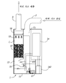
도 1은 본 발명의 일 실시예에 따른 일체형 산화 및 흡수에 의한 탈취장치의 외관을 도시한 정면도이다.
도 2는 본 발명의 일 실시예에 따른 일체형 산화 및 흡수에 의한 탈취장치의 내부 구성을 보인 단면도이다.
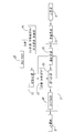
도 3은 본 발명의 일 실시예에 따른 일체형 산화 및 흡수에 의한 탈취장의 흡수 및 산화에 의한 탈취 작용을 순서적으로 보인 블록 구성도이다. FIG. 1 is a front view showing the appearance of a deodorization apparatus by integral oxidation and absorption according to an embodiment of the present invention.
FIG. 2 is a cross-sectional view showing the internal structure of a deodorizing device by integrated oxidation and absorption according to an embodiment of the present invention.
FIG. 3 is a block diagram showing an absorption and deodorization action by oxidation of a deodorizing field by the integrated oxidation and absorption according to an embodiment of the present invention.
이하, 첨부된 도면에 따라 본 발명의 바람직한 실시예를 상세히 설명한다. 첨부된 도면 및 이에 관한 설명은 당해 기술분야에서 통상의 지식을 가진 자로 하여금 본 발명에 관한 이해를 돕기 위한 의도로 제공되는 것이다. 따라서, 도면 및 설명이 본 발명의 범위를 한정하는 것으로 해석되어서는 아니될 것이다.Hereinafter, preferred embodiments of the present invention will be described in detail with reference to the accompanying drawings. BRIEF DESCRIPTION OF THE DRAWINGS The accompanying drawings and the description are intended for a person skilled in the art to assist in understanding the present invention. Accordingly, the drawings and description are not to be construed as limiting the scope of the invention.
도 1은 본 발명의 일 실시예에 따른 일체형 산화 및 흡수에 의한 탈취장치의 외관을 도시한 정면도이고, 도 2는 본 발명의 일 실시예에 따른 일체형 산화 및 흡수에 의한 탈취장치의 내부 구성을 보인 단면도이며, 도 3은 본 발명의 일 실시예에 따른 일체형 산화 및 흡수에 의한 탈취장치의 흡수 및 산화에 의한 탈취 작용을 순서적으로 보인 블록 구성도이다. FIG. 1 is a front view showing an outer appearance of a deodorizing device by integrated oxidation and absorption according to an embodiment of the present invention, and FIG. 2 is a front view showing the internal structure of a deodorizing device by integrated oxidation and absorption according to an embodiment of the present invention. And FIG. 3 is a block diagram showing the deodorization action by absorption and oxidation of the deodorization device by integrated oxidation and absorption according to an embodiment of the present invention in order.
도 1을 참조하면, 본 발명의 일 실시예에 따른 일체형 산화 및 흡수에 의한 탈취장치(이하 "탈취장치"라 함)은, 본체(1)와, 상기 본체(1)의 상부에 일체로 결합된 악취 가스 유입구(2) 및 처리 가스 배출구(3)를 포함한다. 상기 탈취장치는 상기 악취 가스 유입구(2)를 통해 본체(1) 내로 유입된 악취 가스를 산화 및 흡수를 이용해 처리하는 구성요소들을 상기 본체(1) 내에 일체로 포함한다. 산화 및 흡수 작용에 의해 악취 성분이 제거된 가스, 즉, 처리 가스는 상기 처리 가스 배출구(3)를 통해 외부로 배출된다. 상기 본체(1)의 외부 일면에는 탈취챔버(C, 흡수에 의한 시설 ; 스크라바), 이산화염소 발생기(4) 및 오퍼레이터(또는, 작업자)가 상기 탈취장치의 프로세스를 입력 실행할 수 있도록 조작반(5)이 일체로 설치된다.Referring to FIG. 1, a deodorization apparatus (hereinafter referred to as "deodorization apparatus") according to an embodiment of the present invention includes a
도 2를 참조하면, 본 실시예에 따른 탈취장치는 상기 악취 가스 유입구(2)로부터 상기 처리 가스 배출구(3)로 이어지는 가스 유동 경로가 상기 본체(1) 내에 형성된다. 또한, 상기 탈취장치는 일정량의 흡수액을 저장하는 흡수액조(11)와, 상기 흡수액조(11)의 상측에 배치되는 충전재층(12)과, 상기 충전재층(12) 상측에 배치되는 분사노즐(13)과, 산화제를 발생시켜 상기 흡수액조(11)에 저장된 흡수액에 공급하는 산화제 공급유닛(14)과, 상기 흡수액조(11) 내에 설치되어 상기 흡수액 내 산화제 농도를 측정하는 산화제 농도 측정부(15)를 포함한다. 또한, 상기 탈취장치는 분사노즐(13)의 상측에 위치하는 상기 처리 가스 배출구(3)의 직하에 데미스터(16)를 포함하는데, 상기 데미스터(16)는 분사노즐(13)을 통한 흡수액 분사로 인해 발생된 흡수액 입자가 상기 처리 가스 배출구(3)를 통해 외부로 배출되는 것을 차단한다. 또한, 상기 탈취장치는 상기 흡수액조(11)에 수용된 흡수액을 상기 분사노즐(13)로 펌핑해 공급하는 스프레이 펌프(17)를 포함한다.Referring to FIG. 2, the deodorizing apparatus according to the present embodiment is formed in the
본 실시예에서, 상기 가스 유동 경로는 상기 악취 가스 유입구(2)로부터 흡수액조(11) 상측 영역까지 아래로 이어진 유입통로(f1)와, 상기 흡수액조(11)의 상측 영역에서 상기 유입통로(f1)와 만나며 상기 흡수액조(11) 상측 영역으로부터 상기 충전재층(12), 상기 분사노즐(13) 설치 영역 및 상기 데미스터(16) 설치 영역을 차례로 걸쳐 상기 처리 가스 배출구(3)로 이어진 배출통로(f2)를 포함한다.The gas flow path includes an inflow passage f1 extending downward from the
상기 충전재층(12)은 다수의 기공이 형성된 바닥을 포함하는 탈취챔버(C) 내에 일정 높이로 채워져 형성되며, 상기 분사노즐(3)은 상기 탈취챔버(C) 상측으로 도입되어 배치될 수 있다. 더 나아가, 상기 탈취챔버(C)는 상기 처리 가스 배출구(3)와 직접 연결되도록 형성될 수 있다. 상기 탈취챔버(C)의 측벽에 의해 상기 유입통로(f1)와 상기 배출통로(f2)가 측방향으로 분리되어 있되 상기 탈취챔버(C) 바닥의 기공에 의해 상기 유입통로(f1)와 상기 배출통로(f2)가 연결될 수 있다. 또한, 상기 분사노즐(13)을 통해 분사된 흡수액은 상기 충전재층(12)을 거쳐 상기 흡수액조(11)로 떨어져 회수된다.The
상기 충전재층(12)은 상기 흡수액과 상기 악취 가스의 기액 접촉 면적을 증가시키는 역할을 하며, 또한, 흡수액에 악취 가스 내 악취 성분이 충분히 흡수될 수 있도록, 악취 가스가 배출되지 않고 정체되는 시간을 증가시키는 역할을 한다. The
상기 산화제 공급유닛(14)은 산화제로 이산화염소를 발생시켜 이를 흡수액 내로 공급하는 이산화염소 발생기인 것이 바람직하고, 상기 산화제 농도 측정부(15)는 이산화염소 측정용 ClO2미터인 것이 바람직하다. 상기 산화제 공급유닛(14)은 약품조(142)와 연결되어 약품조(142)로부터 공급된 약품 재료로 이산화염소를 발생시킨다. 또한, 산화제 공급유닛(14)은 제어부를 포함하며, 그 제어부는 산화제 농도 측정부(15)에서 측정된 이산화염소 농도 측정값에 따라 상기 흡수액에 공급하는 이산화염소의 공급량을 제어할 수 있다.Preferably, the
악취 성분을 포함한 가스는 악취 가스 유입구(2)를 통해 유입되어 유입통로(f1)을 거쳐 배출통로(f2)에 있는 탈취챔버(C)로 유입된다. 탈취챔버(C)로 유입된 가스는 충전재층(12), 분사노즐(13) 설치 영역 및 데미스터(16) 설치 영역을 차례로 거쳐 처리 가스 배출구(3)로 배출된다. 이때 흡수액조(11)에 저장된 흡수액이 스프레이 펌프(17)에 의해 스프레이 배관(172)을 거쳐 분사노즐(13)로 공급되며, 분사노즐(13)은 악취 가스가 정체되는 충전재층(12)을 향해 흡수액을 분사한다. 악취 가스 내 악취 성분은 충전재층(12)에 구비된 다수의 충전재(filler)에 의해 기액 접촉 표면적이 넓어진 상태로 충전재층(12) 내에서 흡수액에 흡수되고, 그 흡수 다시 흡수액조(11)로 떨어진 후, 스프레이 펌프(17)에 의해 재순환된다. 여기에서, 분사노즐(13)을 통해 분사된 흡수액은 충전재층(12)과 접촉하지 않은 상태로 악취 성분을 직접 흡수하기도 하고, 또는, 충전재층(12)과 접촉하여 접촉 표면적을 넓혀 악취 성분을 직접 흡수하기도 한다. 흡수액조(11) 내 흡수액은 앞에서 설명한 바와 같이 스프레이 펌프(17)에 의해 연속적으로 재순환되면서 악취 성분의 흡수에 이용되는 한편, 기화로 인해 없어지는 양만큼 외부에서 보충될 수 있다.The gas containing the malodorous component flows through the
한편, 흡수액의 악취 성분 흡수에 의해 탈취가 진행되는 과정, 즉, 흡수액의 악취 성분 흡수 및 재순환 과정의 반복이 지속되면, 흡수액조(11) 내에 저장된 흡수액은 악취 성분으로 포화된다. 이때, 흡수액 내 악취 성분의 제거를 위해 상기 산화제 공급유닛(14)은 산화제 공급관(141)을 통해 산화제인 이산화염소를 흡수액조(10) 내 흡수액에 공급한다. 이산화염소의 주입량은 산화제 농도 측정부(15), 즉, ClO2 미터가 측정한 흡수액 내 이산화염소 농도에 따라 제어되므로, 흡수액조(11)내 흡수액의 이산화염소 농도는 일정하게 유지될 수 있다.On the other hand, if the deodorization progresses due to the absorption of the malodor component of the absorption liquid, that is, the malodor component of the absorption liquid is repeatedly absorbed and recirculated, the absorption liquid stored in the
도 3은 본 발명의 일 실시예에 따른 일체형 산화 및 흡수에 의한 탈취장치의 흡수 및 산화에 의한 탈취 작용을 순서적으로 보인 블록 구성도이다. FIG. 3 is a block diagram showing the deodorizing action by absorption and oxidation of the deodorizing device by integrated oxidation and absorption according to an embodiment of the present invention in order.
도 3을 참조하면, 악취 성분을 포함하는 가스는 악취 가스 유입구(2)를 통해 본체 내로 유입되어 유입통로(f1)를 거친 후, 탈취 챔버(C)로 들어가 충전재층(12), 분사노즐(13) 및 데미스터(9)가 차례로 통과하면서 악취 성분이 제거된 후, 상기 처리 가스 배출구(3)를 통해 배출된다. 흡수액조(11) 내 흡수액은 스프레이 펌프(11)에 의해 분사노즐(8)로 공급된 후, 탈취 챔버(C) 내로 분사되어 탈취 챔버(C) 내 충전재층(12)에서 악취 성분을 충분히 흡수한 후 흡수액조(11)에 회수된다. 그리고, 스프레이 펌프(11)의 작동에 의해, 위 경로를 따르는 흡수액의 재순환이 연속적으로 이루어지면서, 탈취 챔버(C) 내에서의 탈취 작용은 연속적으로 이루어진다. 또한, 이산화염소 발생기를 포함하는 산화제 공급유닛(14)은 ClO2미터로 이루어진 산화제 농도 측정부(15)에서 측정된 이산화염소 농도에 따라 이산화염소 공급량을 제어하여 상기 흡수액조(11)에 이산화염소를 공급한다. 이렇게 함으로써, 흡수액조(11) 내 흡수액의 이산화염소 농도를 일정하게 유지할 수 있고 이를 통해 안정적인 악취 제거 효율을 얻을 수 있다.3, the gas containing the malodorous component flows into the main body through the
본 발명에 따른 일체형 산화 및 흡수에 의한 탈취장치는, 가스 내 악취 성분을 흡수액을 이용한 흡수 작용에 의해 제거할 때, 흡수액에 산화제로 이산화염소를 주입하여, 산화 흡수에 의한 탈취를 동시에 행하며, 이 과정에서, 흡수액에 대한 산화제(이산화염소)의 농도를 일정하게 제어하여, 악취 농도 변화에 관계없이 안정적인 악취제거 효율을 얻을 수 있다. 그리고, 이 모든 공정을 하나의 일체화된 장치 내에서 수행하여 설치 공간을 줄이고 간단하게 제어 할 수 있고 설치 비용을 크게 절감할 수 있는 특징이 있다.According to the present invention, when a malodorous component in a gas is removed by an absorption action using an absorption liquid, the device for deodorization by integrated oxidation and absorption according to the present invention simultaneously injects chlorine dioxide into the absorption liquid with an oxidizing agent, The concentration of the oxidizing agent (chlorine dioxide) with respect to the absorption liquid can be controlled to be constant, and stable odor removal efficiency can be obtained regardless of the change of the odor concentration. In addition, all of these processes are performed in a single integrated device, so that the installation space can be reduced, the control can be simplified, and the installation cost can be greatly reduced.
1: 본체 2: 악취 가스 유입구
3: 처리 가스 배출구 f1: 유입통로
f2: 배출통로 C: 탈취챔버(흡수에 의한 시설; 스크라바)
11: 흡수액조 12: 충전재층
13: 분사노즐 14: 산화제 공급유닛
15: 산화제 농도 측정부(ClO2 미터) 1: Main body 2: Odor gas inlet
3: Process gas outlet f1: Inlet passage
f2: discharge passage C: deodorization chamber (facility by absorption; scrubber)
11: absorption liquid tank 12: filler layer
13: injection nozzle 14: oxidizing agent supply unit
15: Oxidant concentration measuring part (ClO 2 meter)
Claims (6)
상기 본체 내 일측에 설치되며 흡수액을 저장하는 흡수액조;
스프레이 펌프에 의해 상기 흡수액조로부터 공급된 흡수액을 분사하는 분사노즐;
상기 분사노즐을 통해 공급되는 흡수액과의 기액 접촉 표면적 증가를 위해 상기 분사노즐과 상기 흡수액조 사이에 제공된 충전재층;
상기 본체 내 타측에 설치되며, 상기 흡수액조 내 흡수액에 산화액을 공급하여, 상기 흡수액 내 악취 성분을 줄이는 산화제 공급유닛을 포함하는 것을 특징으로 하는 일체형 산화 및 환원에 의한 탈취장치. A deodorizing device for deodorizing odorous components flowing through the gas flow path by absorbing the odorous components into an absorbing solution,
An absorption liquid tank installed at one side of the main body and storing the absorption liquid;
A spray nozzle for spraying the absorption liquid supplied from the absorption liquid tank by a spray pump;
A filler layer provided between the injection nozzle and the absorption liquid tank for increasing the gas-liquid contact surface area with the absorption liquid supplied through the injection nozzle;
And an oxidant supply unit provided on the other side of the main body for supplying an oxidant to the absorption liquid in the absorption liquid tank to reduce odor components in the absorption liquid.
상기 흡수액 내 산화제 농도를 측정하는 산화제 농도 측정부를 더 포함하며, 상기 산화제 공급유닛은, 상기 산화제 농도 측정부에서 측정된 산화제 농도에 따라, 제어된 공급양으로 상기 흡수액에 산화제를 공급하는 것을 특징으로 하는 일체형 산화 및 환원에 의한 탈취장치. The method according to claim 1,
Wherein the oxidant supply unit supplies the oxidant to the absorption liquid at a controlled supply amount in accordance with the oxidant concentration measured by the oxidant concentration measurement unit, characterized by further comprising an oxidant concentration measurement unit for measuring the oxidant concentration in the absorption liquid Wherein the deodorizing device is a single-type oxidation and reduction device.
상기 산화제 공급유닛은 산화제로 이산화염소를 발생시켜 상기 흡수액조 내 흡수액에 공급하는 이산화염소 발생기이며, 상기 산화제 농도 측정부는 상기 흡수액조 내 흡수액의 이산화염소 농도를 측정하는 ClO2미터인 것을 특징으로 하는 일체형 산화 및 환원에 의한 탈취장치. 3. The method of claim 2,
Wherein the oxidant supply unit is a chlorine dioxide generator that generates chlorine dioxide by an oxidant and supplies the chlorine dioxide to the absorption liquid in the absorption liquid tank, and the oxidant concentration measurement unit is a ClO 2 meter for measuring the concentration of chlorine dioxide in the absorption liquid in the absorption liquid tank Deodorization device by integral oxidation and reduction.
상기 가스 유동 경로는 상기 악취 가스 유입구로부터 흡수액조 상측 영역까지 아래로 이어진 유입통로와, 상기 흡수액조의 상측 영역에서 상기 유입통로와 만나며 상기 흡수액조의 상측 영역으로부터 상기 충전재층, 상기 분사노즐의 설치 영역 및 데미스터의 설치 영역을 차례로 걸쳐 상기 처리 가스 배출구로 이어진 배출통로를 포함하는 것을 특징으로 하는 일체형 산화 및 환원에 의한 탈취장치. The method according to claim 1,
Wherein the gas flow path comprises an inflow passageway extending downward from the odor gas inlet to an upper area of the absorption liquid bath and an inflow passageway extending from an upper region of the absorbent bath to the inflow passageway and extending from an upper region of the absorbent bath to the filler layer, And a discharge passage extending to the process gas discharge port in order of the installation area of the demister.
상기 충전재층은 기공이 형성된 바닥을 포함하는 탈취챔버 내에 채워져 형성되고, 상기 분사노즐은 상기 탈취챔버 상측으로 도입되어 배치된 것을 특징으로 하는 일체형 산화 및 환원에 의한 탈취장치.The method according to claim 1,
Wherein the filler layer is formed by being filled in a deodorization chamber including a bottom having pores formed therein, and the injection nozzle is introduced and arranged above the deodorization chamber.
상기 탈취챔버는, 상기 처리 가스 배출구와 직접 연결되어 상기 유입통로를 거친 가스를 상기 처리 가스 배출구로 배출하되, 상기 가스가 유입되어 상기 처리 가스 배출구로 흐르는 방향을 따라, 상기 충전재층과 상기 분사노즐의 설치 영역을 차례로 포함하는 것을 특징으로 하는 일체형 산화 및 환원에 의한 탈취장치.6. The method of claim 5,
Wherein the deodorization chamber is connected to the process gas outlet so as to discharge the gas passing through the inlet passageway to the process gas discharge port and along the direction of flow of the gas to the process gas discharge port, And a mounting area of the deodorizing device.
Priority Applications (1)
| Application Number | Priority Date | Filing Date | Title |
|---|---|---|---|
| KR1020150045632A KR20160117841A (en) | 2015-03-31 | 2015-03-31 | Deodorization apparatus using oxidation and absorption |
Applications Claiming Priority (1)
| Application Number | Priority Date | Filing Date | Title |
|---|---|---|---|
| KR1020150045632A KR20160117841A (en) | 2015-03-31 | 2015-03-31 | Deodorization apparatus using oxidation and absorption |
Publications (1)
| Publication Number | Publication Date |
|---|---|
| KR20160117841A true KR20160117841A (en) | 2016-10-11 |
Family
ID=57161757
Family Applications (1)
| Application Number | Title | Priority Date | Filing Date |
|---|---|---|---|
| KR1020150045632A Ceased KR20160117841A (en) | 2015-03-31 | 2015-03-31 | Deodorization apparatus using oxidation and absorption |
Country Status (1)
| Country | Link |
|---|---|
| KR (1) | KR20160117841A (en) |
Cited By (1)
| Publication number | Priority date | Publication date | Assignee | Title |
|---|---|---|---|---|
| KR102275719B1 (en) * | 2020-12-07 | 2021-07-09 | 수도권매립지관리공사 | Biogas biological desulfurization facility |
Citations (1)
| Publication number | Priority date | Publication date | Assignee | Title |
|---|---|---|---|---|
| KR960004313A (en) | 1994-07-07 | 1996-02-23 | 프리돌린 클라우스너, 롤란드 보러 | Asymmetric Hydrogenation of Ketoisophorone Derivatives |
-
2015
- 2015-03-31 KR KR1020150045632A patent/KR20160117841A/en not_active Ceased
Patent Citations (1)
| Publication number | Priority date | Publication date | Assignee | Title |
|---|---|---|---|---|
| KR960004313A (en) | 1994-07-07 | 1996-02-23 | 프리돌린 클라우스너, 롤란드 보러 | Asymmetric Hydrogenation of Ketoisophorone Derivatives |
Cited By (1)
| Publication number | Priority date | Publication date | Assignee | Title |
|---|---|---|---|---|
| KR102275719B1 (en) * | 2020-12-07 | 2021-07-09 | 수도권매립지관리공사 | Biogas biological desulfurization facility |
Similar Documents
| Publication | Publication Date | Title |
|---|---|---|
| KR100972921B1 (en) | An apparatus for cleaning and deodorizing of rotation diaphragmed type vortex | |
| KR101653368B1 (en) | Deodorizing device | |
| KR101372106B1 (en) | System for pre-treating of odor | |
| KR101669805B1 (en) | Deodorization type scrubber | |
| KR101286198B1 (en) | Offensive odor treatment system using micro bubble | |
| US20170021049A1 (en) | Air purifier for bringing gas into contact with plasma-treated liquid | |
| KR101581236B1 (en) | Dust Collector using Ozon Water | |
| US20170028095A1 (en) | Air purifier for bringing gas into contact with plasma-treated liquid | |
| KR100966737B1 (en) | Deodorizing tower for chemical cleaning | |
| KR101733375B1 (en) | Complex deodorizer | |
| KR102188763B1 (en) | apparatus for removing odor | |
| KR101874952B1 (en) | Multistage Cleaning Deodorizing Device using Circulating Contact Flow Path | |
| KR101823139B1 (en) | Tunnel type ozone water odor remving facilities | |
| KR102242287B1 (en) | Facility for complex odor removal | |
| KR20160117841A (en) | Deodorization apparatus using oxidation and absorption | |
| KR100540217B1 (en) | Vortex mix type deodorizer and deodorization method using the deodorizer | |
| JP5808030B1 (en) | Air purifier | |
| KR101765189B1 (en) | Stink gas deodorization device | |
| JP6069760B2 (en) | Deodorizing device and deodorizing method | |
| KR102018109B1 (en) | Module type Scrubber for odor removal | |
| KR101896065B1 (en) | odor treatment apparatus | |
| KR102217994B1 (en) | Stinking gas removal device | |
| KR102116253B1 (en) | Scrubber Apparatus For Simultaneous removal of Odor And NOx, And method thereof | |
| KR102207656B1 (en) | Electron beam treatment method of air pollutants and treatment device therefor | |
| KR101006615B1 (en) | Deodorizer and Scrubber |
Legal Events
| Date | Code | Title | Description |
|---|---|---|---|
| A201 | Request for examination | ||
| PA0109 | Patent application |
Patent event code: PA01091R01D Comment text: Patent Application Patent event date: 20150331 |
|
| PA0201 | Request for examination | ||
| E902 | Notification of reason for refusal | ||
| PE0902 | Notice of grounds for rejection |
Comment text: Notification of reason for refusal Patent event date: 20151014 Patent event code: PE09021S01D |
|
| AMND | Amendment | ||
| E601 | Decision to refuse application | ||
| PE0601 | Decision on rejection of patent |
Patent event date: 20160716 Comment text: Decision to Refuse Application Patent event code: PE06012S01D Patent event date: 20151014 Comment text: Notification of reason for refusal Patent event code: PE06011S01I |
|
| AMND | Amendment | ||
| PX0901 | Re-examination |
Patent event code: PX09011S01I Patent event date: 20160716 Comment text: Decision to Refuse Application Patent event code: PX09012R01I Patent event date: 20160213 Comment text: Amendment to Specification, etc. |
|
| PX0601 | Decision of rejection after re-examination |
Comment text: Decision to Refuse Application Patent event code: PX06014S01D Patent event date: 20161010 Comment text: Amendment to Specification, etc. Patent event code: PX06012R01I Patent event date: 20160902 Comment text: Decision to Refuse Application Patent event code: PX06011S01I Patent event date: 20160716 Comment text: Amendment to Specification, etc. Patent event code: PX06012R01I Patent event date: 20160213 Comment text: Notification of reason for refusal Patent event code: PX06013S01I Patent event date: 20151014 |
|
| PG1501 | Laying open of application |