KR20160108994A - Method and apparatus for reference signal pattern design in multicarrier system - Google Patents
Method and apparatus for reference signal pattern design in multicarrier system Download PDFInfo
- Publication number
- KR20160108994A KR20160108994A KR1020150032548A KR20150032548A KR20160108994A KR 20160108994 A KR20160108994 A KR 20160108994A KR 1020150032548 A KR1020150032548 A KR 1020150032548A KR 20150032548 A KR20150032548 A KR 20150032548A KR 20160108994 A KR20160108994 A KR 20160108994A
- Authority
- KR
- South Korea
- Prior art keywords
- pattern
- cell
- information
- base station
- cells
- Prior art date
- Legal status (The legal status is an assumption and is not a legal conclusion. Google has not performed a legal analysis and makes no representation as to the accuracy of the status listed.)
- Granted
Links
Images


Classifications
-
- H—ELECTRICITY
- H04—ELECTRIC COMMUNICATION TECHNIQUE
- H04L—TRANSMISSION OF DIGITAL INFORMATION, e.g. TELEGRAPHIC COMMUNICATION
- H04L27/00—Modulated-carrier systems
- H04L27/26—Systems using multi-frequency codes
- H04L27/2601—Multicarrier modulation systems
- H04L27/2602—Signal structure
- H04L27/261—Details of reference signals
- H04L27/2613—Structure of the reference signals
- H04L27/26134—Pilot insertion in the transmitter chain, e.g. pilot overlapping with data, insertion in time or frequency domain
-
- H—ELECTRICITY
- H04—ELECTRIC COMMUNICATION TECHNIQUE
- H04L—TRANSMISSION OF DIGITAL INFORMATION, e.g. TELEGRAPHIC COMMUNICATION
- H04L25/00—Baseband systems
- H04L25/02—Details ; arrangements for supplying electrical power along data transmission lines
- H04L25/0202—Channel estimation
- H04L25/0204—Channel estimation of multiple channels
-
- H—ELECTRICITY
- H04—ELECTRIC COMMUNICATION TECHNIQUE
- H04L—TRANSMISSION OF DIGITAL INFORMATION, e.g. TELEGRAPHIC COMMUNICATION
- H04L27/00—Modulated-carrier systems
- H04L27/26—Systems using multi-frequency codes
-
- H—ELECTRICITY
- H04—ELECTRIC COMMUNICATION TECHNIQUE
- H04L—TRANSMISSION OF DIGITAL INFORMATION, e.g. TELEGRAPHIC COMMUNICATION
- H04L27/00—Modulated-carrier systems
- H04L27/26—Systems using multi-frequency codes
- H04L27/2601—Multicarrier modulation systems
- H04L27/2602—Signal structure
- H04L27/261—Details of reference signals
- H04L27/2613—Structure of the reference signals
- H04L27/26132—Structure of the reference signals using repetition
-
- H—ELECTRICITY
- H04—ELECTRIC COMMUNICATION TECHNIQUE
- H04L—TRANSMISSION OF DIGITAL INFORMATION, e.g. TELEGRAPHIC COMMUNICATION
- H04L27/00—Modulated-carrier systems
- H04L27/26—Systems using multi-frequency codes
- H04L27/2601—Multicarrier modulation systems
- H04L27/2626—Arrangements specific to the transmitter only
- H04L27/2627—Modulators
- H04L27/264—Pulse-shaped multi-carrier, i.e. not using rectangular window
- H04L27/26416—Filtering per subcarrier, e.g. filterbank multicarrier [FBMC]
-
- H—ELECTRICITY
- H04—ELECTRIC COMMUNICATION TECHNIQUE
- H04L—TRANSMISSION OF DIGITAL INFORMATION, e.g. TELEGRAPHIC COMMUNICATION
- H04L27/00—Modulated-carrier systems
- H04L27/26—Systems using multi-frequency codes
- H04L27/2601—Multicarrier modulation systems
- H04L27/2647—Arrangements specific to the receiver only
- H04L27/2655—Synchronisation arrangements
- H04L27/2668—Details of algorithms
- H04L27/2669—Details of algorithms characterised by the domain of operation
- H04L27/2671—Time domain
-
- H—ELECTRICITY
- H04—ELECTRIC COMMUNICATION TECHNIQUE
- H04L—TRANSMISSION OF DIGITAL INFORMATION, e.g. TELEGRAPHIC COMMUNICATION
- H04L5/00—Arrangements affording multiple use of the transmission path
- H04L5/0001—Arrangements for dividing the transmission path
- H04L5/0014—Three-dimensional division
- H04L5/0023—Time-frequency-space
-
- H—ELECTRICITY
- H04—ELECTRIC COMMUNICATION TECHNIQUE
- H04L—TRANSMISSION OF DIGITAL INFORMATION, e.g. TELEGRAPHIC COMMUNICATION
- H04L5/00—Arrangements affording multiple use of the transmission path
- H04L5/003—Arrangements for allocating sub-channels of the transmission path
- H04L5/0037—Inter-user or inter-terminal allocation
-
- H—ELECTRICITY
- H04—ELECTRIC COMMUNICATION TECHNIQUE
- H04L—TRANSMISSION OF DIGITAL INFORMATION, e.g. TELEGRAPHIC COMMUNICATION
- H04L5/00—Arrangements affording multiple use of the transmission path
- H04L5/003—Arrangements for allocating sub-channels of the transmission path
- H04L5/0048—Allocation of pilot signals, i.e. of signals known to the receiver
- H04L5/005—Allocation of pilot signals, i.e. of signals known to the receiver of common pilots, i.e. pilots destined for multiple users or terminals
-
- H—ELECTRICITY
- H04—ELECTRIC COMMUNICATION TECHNIQUE
- H04L—TRANSMISSION OF DIGITAL INFORMATION, e.g. TELEGRAPHIC COMMUNICATION
- H04L5/00—Arrangements affording multiple use of the transmission path
- H04L5/003—Arrangements for allocating sub-channels of the transmission path
- H04L5/0048—Allocation of pilot signals, i.e. of signals known to the receiver
- H04L5/0051—Allocation of pilot signals, i.e. of signals known to the receiver of dedicated pilots, i.e. pilots destined for a single user or terminal
-
- H—ELECTRICITY
- H04—ELECTRIC COMMUNICATION TECHNIQUE
- H04L—TRANSMISSION OF DIGITAL INFORMATION, e.g. TELEGRAPHIC COMMUNICATION
- H04L5/00—Arrangements affording multiple use of the transmission path
- H04L5/003—Arrangements for allocating sub-channels of the transmission path
- H04L5/0058—Allocation criteria
- H04L5/0073—Allocation arrangements that take into account other cell interferences
-
- H—ELECTRICITY
- H04—ELECTRIC COMMUNICATION TECHNIQUE
- H04L—TRANSMISSION OF DIGITAL INFORMATION, e.g. TELEGRAPHIC COMMUNICATION
- H04L5/00—Arrangements affording multiple use of the transmission path
- H04L5/0091—Signalling for the administration of the divided path, e.g. signalling of configuration information
- H04L5/0094—Indication of how sub-channels of the path are allocated
-
- H—ELECTRICITY
- H04—ELECTRIC COMMUNICATION TECHNIQUE
- H04L—TRANSMISSION OF DIGITAL INFORMATION, e.g. TELEGRAPHIC COMMUNICATION
- H04L27/00—Modulated-carrier systems
- H04L27/26—Systems using multi-frequency codes
- H04L27/2601—Multicarrier modulation systems
- H04L27/2626—Arrangements specific to the transmitter only
- H04L27/2627—Modulators
- H04L27/264—Pulse-shaped multi-carrier, i.e. not using rectangular window
-
- H—ELECTRICITY
- H04—ELECTRIC COMMUNICATION TECHNIQUE
- H04L—TRANSMISSION OF DIGITAL INFORMATION, e.g. TELEGRAPHIC COMMUNICATION
- H04L27/00—Modulated-carrier systems
- H04L27/26—Systems using multi-frequency codes
- H04L27/2601—Multicarrier modulation systems
- H04L27/2647—Arrangements specific to the receiver only
- H04L27/2649—Demodulators
- H04L27/26534—Pulse-shaped multi-carrier, i.e. not using rectangular window
- H04L27/2654—Filtering per subcarrier, e.g. filterbank multicarrier [FBMC]
-
- H—ELECTRICITY
- H04—ELECTRIC COMMUNICATION TECHNIQUE
- H04L—TRANSMISSION OF DIGITAL INFORMATION, e.g. TELEGRAPHIC COMMUNICATION
- H04L5/00—Arrangements affording multiple use of the transmission path
- H04L5/0001—Arrangements for dividing the transmission path
- H04L5/0003—Two-dimensional division
- H04L5/0005—Time-frequency
- H04L5/0007—Time-frequency the frequencies being orthogonal, e.g. OFDM(A) or DMT
Landscapes
- Engineering & Computer Science (AREA)
- Signal Processing (AREA)
- Computer Networks & Wireless Communication (AREA)
- Power Engineering (AREA)
- Mobile Radio Communication Systems (AREA)
Abstract
본 발명은 FBMC 송수신 기법을 기반으로 하는 셀룰러 환경에서 채널 추정 및 등화에 관한 것으로, 본 발명의 일 실시예에 따른 기지국의 통신 방법은, 복수의 셀들의 필터 정보에 따라 상기 복수의 셀들의 기준 신호(RS: reference signal) 패턴 빌딩 블록을 결정하는 단계; 상기 결정된 RS 패턴 빌딩 블록 및 자원 블록(RB: resource block) 크기(size)를 이용하여 상기 복수의 셀들의 RS 패턴을 결정하는 단계; 및 상기 결정된 RS 패턴에 대한 정보를 단말에게 전송하는 단계;를 포함할 수 있다. 본 발명의 일 실시예에 따르면, 다중 셀 환경에서 기준 신호 매핑 방법 및 장치를 제공할 수 있다. The present invention relates to channel estimation and equalization in a cellular environment based on an FBMC transmission / reception scheme, and a communication method of a base station according to an embodiment of the present invention includes: Determining a reference signal (RS) pattern building block; Determining an RS pattern of the plurality of cells using the determined RS pattern building block and a resource block size; And transmitting information on the determined RS pattern to a mobile station. According to an embodiment of the present invention, a reference signal mapping method and apparatus in a multi-cell environment can be provided.
Description
본 발명은 필터 뱅크 멀티캐리어(FBMC: Filter-Bank Multi-Carrier) 송수신 기법을 기반으로 하는 셀룰러 환경에서 채널 추정 및 등화(Equalization)에 관한 것으로서, 기준 신호(RS: reference signal)을 매핑(Mapping)하는 방법 및 장치에 관한 것이다. The present invention relates to channel estimation and equalization in a cellular environment based on a filter-bank multi-carrier (FBMC) transmission / reception technique, and includes mapping a reference signal (RS) And more particularly,
다중 캐리어 시스템, 예를 들면 직교 주파수 분할 다중(OFDM: Orthogonal Frequency Division Multiplexing) 시스템에서, 주파수 톤(tone)들 또는 서브캐리어(subcarrier)들은 서로 직교한다. 완벽한 동기화(synchronization) 상태에서, 신호들은 서브캐리어간(inter-subcarrier) 간섭을 겪지 않는다. LTE(long term evolution) 시스템의 CP-OFDM(cyclic prefix based OFDM) 기술에서는 서브캐리어들이 서로 직교하도록 설정된다. 이러한 직교성은 시스템 디자인을 간소화게 하고, 복잡도 계산을 줄여준다. In multi-carrier systems, such as Orthogonal Frequency Division Multiplexing (OFDM) systems, frequency tones or subcarriers are orthogonal to one another. In a perfect synchronization state, the signals do not suffer inter-subcarrier interference. In a cyclic prefix based OFDM (CP-OFDM) technique of an LTE (long term evolution) system, subcarriers are set to be orthogonal to each other. This orthogonality simplifies system design and reduces complexity calculations.
반면, LTE의 다음 세대 5G 기술에 있어서는 멀티 캐리어(multi carrier) 시스템에 초점을 맞추고 있으며, 이들은 더 이상 직교성을 만족하지 않을 수 있다. 예를 들면, 필터 뱅크 멀티캐리어(FBMC: Filter-Bank Multi-Carrier) 시스템의 경우, 개선된 스펙트럼 효율(spectral efficiency) 및 스펙트럼 컴파인먼트(spectrum confinement)를 위하여 서브캐리어들은 서로 직교하지 않고, 신호들은 필터들로 변조된다. 순환 전치(cyclic prefix) 및 직교성을 도입하지 않은 것은 스펙트럼 효율을 높게 하고 시간 및 주파수 동기 오프셋에 덜 민감하게 할 수 있다. 이때, 각각의 데이터는 각각의 주파수 서브캐리어(예를 들면, M 개의)에 의해 변조되고(modulated), 선택된 필터 뱅크를 통과한 후, 푸리에 변환(Fourier transform)을 거치게 된다. 각각의 서브캐리어가 통과하는 필터에 의해서, FBMC 심볼(symbol)은 원래의 길이에 비해 L 배 증가하게 된다. 따라서, 시간 도메인(time domain)에서 각각의 FBMC 심볼의 길이 N = LM이 된다. 시간 도메인에서 연석된 FMBC 심볼들은 오버랩(overlap)되고, 합쳐진다(sum up). 이때 변조 방식에 따라서 오버랩되는 심볼의 개수는 변할 수 있다. 그러나, 주파수 도메인(frequency domain)의 직교성이 없음으로 인하여 현재 셀의 주파수 서브캐리어와 이와 동일한 주파수를 사용하는 이웃 셀의 주파수 서브캐리어간 상호 간섭이 발생할 수 있다. 그리고, 이러한 서브캐리어간 간섭은 FBMC 시스템의 모든 모듈(module), 예를 들면 채널 추정(channel estimation), 동기화(synchronization), 등화(equalization) 등에 영향을 미치게 된다. 이 경우, 상기 오버랩되는 심볼의 개수는 간섭 심볼의 개수가 될 수 있다. FBMC 심볼 각각은 간섭 심볼에 의해 각각의 주파수 요소에서 간섭이 발생한다. On the other hand, LTE's next generation 5G technology focuses on multi-carrier systems, which may no longer satisfy orthogonality. For example, in the case of a filter-bank multi-carrier (FBMC) system, subcarriers are not orthogonal to each other for improved spectral efficiency and spectrum confinement, Are modulated with filters. Not introducing a cyclic prefix and orthogonality can increase spectral efficiency and make it less sensitive to time and frequency synchronization offsets. At this time, each data is modulated by each frequency subcarrier (e.g., M), passed through a selected filter bank, and then undergoes a Fourier transform. The filter through which each subcarrier passes causes the FBMC symbol to increase L times the original length. Therefore, the length of each FBMC symbol in the time domain becomes N = LM. The curved FMBC symbols in the time domain are overlapped and summed up. At this time, the number of overlapped symbols may vary depending on the modulation scheme. However, since there is no orthogonality of the frequency domain, mutual interference between frequency subcarriers of the current cell and neighboring cells using the same frequency may occur. This inter-subcarrier interference affects all the modules of the FBMC system, for example, channel estimation, synchronization, equalization, and the like. In this case, the number of overlapping symbols may be the number of interference symbols. Each of the FBMC symbols is subject to interference at each frequency element by an interference symbol.
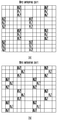
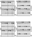
도 1은 공동(coordinative) 멀티포인트(multipoint) 시나리오의 일 예를 도시한 도면이고, 도 2는 LTE 시스템에서 셀 별 셀 특정 참조 신호(CRS: cell specific reference signal) 자원 매핑에 대해 도시한 도면이고, 도 3은 LTE 시스템에서 CRS 자원 매핑에 대해 도시한 도면이고, 도 4는 FBMC를 가정한 경우의 셀 별 CRS 자원 매핑의 일 예를 도시한 도면이고, 도 5는 FBMC를 가정한 경우의 종래 기술에 따른 CRS 자원 매핑의 일 예를 도시한 도면이다. FIG. 1 is a diagram illustrating an example of a coordinative multipoint scenario, FIG. 2 is a diagram illustrating cell-specific reference signal (CRS) resource mapping in a LTE system , FIG. 3 is a diagram illustrating a CRS resource mapping in an LTE system, FIG. 4 is a diagram illustrating an example of a CRS resource mapping per cell when an FBMC is assumed, FIG. Lt; RTI ID = 0.0 > CRS < / RTI >
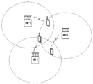
도 1을 참고하면 멀티 셀(multi cell) 환경이 도시되어 있다. 엑세스 포인트(access point) 또는 기지국(base station, evolve node B, eNB)은 다양한 레벨로 협동하여 단말기와 신호를 송수신할 수 있다. 이러한 시나리오는 LTE advanced 환경에서는 공동 멀티포인트(CoMP: coordinative multipoint)를 포함할 수 있다. 이때, 모든 셀들이 전부 협동을 하게 되는 경우, 협동 전송(joint transmission)이 가능하고, 단말은 복수의 엑세스 포인트로부터 신호를 수신할 수 있다. 낮은 협동 상황에서는 단말이 심 없이(seamlessly) 셀 간 전환(switch)를 할 수 있고, 이는 동적 셀 선택일 수 있다. 사용자 스케줄링 및 빔포밍(beamforming) 결정의 협동을 통해, 단말은 서빙 셀(serving cell)로부터만 데이터를 수신할 수 있다. 그러나 이때, 다른 셀들로부터의 신호는 간섭이 될 수 있고 이는 상기 협동 작용을 감소시킬 수 있다. Referring to FIG. 1, a multi-cell environment is illustrated. An access point or a base station (evolve node B, eNB) can cooperate at various levels to transmit / receive signals to / from a terminal. These scenarios may include coordinative multipoint (CoMP) in an LTE advanced environment. At this time, when all of the cells are cooperated, joint transmission is possible, and the terminal can receive signals from a plurality of access points. In a low cooperative situation, the UE may seamlessly switch between cells, which may be a dynamic cell selection. Through cooperation of user scheduling and beamforming decisions, a terminal can only receive data from a serving cell. At this time, however, the signals from other cells may be interference, which may reduce the cooperative action.
이러한 동작을 위해서는 채널 정보가 필수적이다. 특히 LTE 표준에서는 CRS가 채널 품질 측정, 랭크-적응적(rank-adaptive) 멀티플렉싱(multiplexing), 및 폐루프(closed loop) 및 개루프(open loop) 멀티플렉싱 추천(recommendation)에 있어서 필수적이다. 이때, C-RS는 이웃 셀들의 셀 식별자(cell-id)에 따른 주파수 쉬프트(shift)가 이루어진다. Channel information is essential for this operation. Particularly in the LTE standard, CRS is essential for channel quality measurements, rank-adaptive multiplexing, and closed-loop and open-loop multiplexing recommendations. At this time, the C-RS is shifted in frequency according to the cell-id of the neighboring cells.
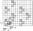
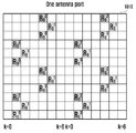
도 2 및 도 3을 참고하면, 셀 별 CRS 자원의 주파수(frequency) 및 시간(time) 도메인(domain) 상의 위치가 도시되어 있다. 예를 들면, 도 2에 도시된 바와 같이 제1 셀(또는 셀 1)을 위한 CRS(215)가 도면부호 210으로 도시된 바와 같이 매핑될 수 있다. 또한 제2 셀(또는 셀 2)을 위한 CRS(225), 제3 셀(또는 셀 3)을 위한 CRS(235)가 각각 도면부호 220, 230으로 도시된 바와 같이 매핑될 수 있다. 이때, 도시된 바와 같이 이웃 셀의 CRS들은 서로 겹치지 않고 매핑될 수 있다. 예를 들면, 제2 셀을 위한 CRS(225)는 제1 셀을 위한 CRS(215) 및 제3 셀을 위한 CRS(235)와 비교하여 주파수 방향의 쉬프트가 이루어져 매핑될 수 있다. 유사하게 제3 셀을 위한 CRS(235)는 제1 셀을 위한 CRS(215), 제2 셀을 위한 CRS(225)와 비교하여 주파수 방향의 쉬프트가 이루어져 매핑될 수 있다. 이에 따라, 도 3의 350으로 도시된 바와 같이 각 셀의 CRS들은 주파수 및 시간 도메이 상에서 겹치지 않고 매핑될 수 있다. Referring to Figures 2 and 3, the frequency and location on the time domain of the per-cell CRS resource are shown. For example, the
그런데, FBMC 시스템의 경우 상술한 바와 같은 서브캐리어간 간섭으로 인하여, LTE 시스템의 RS 패턴의 주파수 쉬프트를 그대로 적용하는 경우 채널 추정이 불충분하게(unsatisfactory) 이루어질 수 있다. 이때, 정확한 간섭은 필터 뱅크의 정확한 디자인에 따를 수 있다. 그러나, 가까운 간섭이 가장 강한 간섭이므로, 다중경로(multipath) 채널로 인해 앞선 심볼은 뒤따르는 심볼에 비하여 강한 간섭을 겪을 수 있다. 도 4 및 도 5를 참고하면, 자원 블록(RB: resource block)의 각각의 신호들은 이웃 심볼로 인하여 주파수 및 시간 도메인 상에서 간섭을 겪을 수 있다. 예를 들면, 도 4에 도시된 바와 같이 제1 셀을 위한 CRS(415)가 도면부호 410으로 도시된 바와 같이 매핑될 수 있다. 이때, FBMC 시스템의 경우 직교성이 보장되지 않으므로, 시간 및 주파수 도메인 상에서 주변 자원 요소에 간섭(417)을 일으킬 수 있다. 마찬가지로 420, 430으로 도시된 바와 같이 제2 셀을 위한 CRS(425), 제3 셀을 위한 CRS(435)가 주변 자원 요소(427, 437)을 일으킬 수 있다. 그 결과 도 5에 450으로 도시된 바와 같이 다중 셀 환경에서 종래 기술에 따라 CRS(455)를 쉬프트하여 매핑한 경우에 주변 셀의 신호가 간섭(457)으로 작용할 수 있다. However, in the case of the FBMC system, channel estimation may be unsatisfactory when the frequency shift of the RS pattern of the LTE system is directly applied due to the inter-subcarrier interference as described above. At this time, the correct interference can follow the exact design of the filter bank. However, since the near interference is the strongest interference, the preceding symbol may experience strong interference with the following symbol due to the multipath channel. Referring to FIG. 4 and FIG. 5, each of the signals of the resource block (RB) may undergo interference in the frequency and time domain due to the neighboring symbols. For example, the
서브캐리어간 간섭을 고려한 채널 추정 방법, 예를 들면 파일럿-쌍 방법(pair-of-pilots), 간섭 근사 방법(IAM: interference approximation method) 및 간섭 선-제거 기술(interference pre- subtraction technique)의 경우에 있어서도, 동일한 채널 상의 동일한 셀에 의한 간섭만을 고려하고 있다. 그리고 이는 다중-셀(multi-cell) 간섭에 적용될 수 없다. In the case of a channel estimation method considering inter-subcarrier interference, for example, a pair-of-pilots, an interference approximation method (IAM) and an interference pre- subtraction technique , Only interference by the same cell on the same channel is considered. And this can not be applied to multi-cell interference.
본 발명은 상술한 문제점을 해결하기 위한 것으로, 다중 셀 환경에서 기준 신호 매핑 방법 및 장치를 제공하는 것을 목적으로 한다. SUMMARY OF THE INVENTION It is an object of the present invention to provide a reference signal mapping method and apparatus in a multi-cell environment.
또한, 다중 셀 기준 신호 자원 매핑에 있어서, 시간 및 주파수 도메인 상에서 이웃 심볼 및 이웃 셀에 의한 간섭을 감소시키는 것을 목적으로 한다. It is also an object in multi-cell reference signal resource mapping to reduce interference by neighboring symbols and neighboring cells in the time and frequency domains.
그에 따라 상호 간섭의 완화, 다중 안테나(multi-antenna)의 집적 특성(nested property) 만족, 서로 다른 안테나 포트의 기준 신호 심볼이 중첩되지 않게 하고, 다른 안테나 포트의 기준 신호 심볼들이 다른 기준 신호 심볼들로 인하여 발생한 간섭이 강한 영역에 배치되지 않도록 함으로써 기준 신호 심볼들을 시간-주파수 도메인 상에 매핑함으로써 채널 추정 결과를 개선시키는 것을 목적으로 한다. Accordingly, the mutual interference is mitigated, the nested property of the multi-antenna is satisfied, the reference signal symbols of the different antenna ports are not overlapped, and the reference signal symbols of the different antenna ports are different from the reference signal symbols So as not to be placed in a strong region, thereby improving the channel estimation result by mapping the reference signal symbols on the time-frequency domain.
또한, 셀 식별 정보(cell-id)에 따라 특정 주파수 및 시간 쉬프트(shift) 값을 정하는 것을 목적으로 한다. It is also intended to set a specific frequency and a time shift value according to the cell identification information (cell-id).
또한, 이웃 셀 및 안테나 포트에 따른 기준 신호가 오버랩되지 않도록 기준 신호를 매핑하는 것을 목적으로 한다. It is another object of the present invention to map reference signals so that reference signals according to neighboring cells and antenna ports do not overlap.
또한, 이웃 셀 및 안테나 포트에 따른 기준 신호가 강한 간섭 영역에 배치되지 않도록 기준 신호를 매핑하는 것을 목적으로 한다. It is another object of the present invention to map a reference signal so that reference signals according to neighboring cells and antenna ports are not placed in a strong interference region.
또한, 종래 기술에 비하여 동일한 기준 신호 밀도로 기준 신호를 자원 블록에 매핑하는 것을 목적으로 한다. It is also intended to map a reference signal to a resource block with the same reference signal density as in the prior art.
본 발명에서 이루고자 하는 기술적 과제들은 이상에서 언급한 기술적 과제들로 제한되지 않으며, 언급하지 않은 또 다른 기술적 과제들은 아래의 기재로부터 본 발명이 속하는 기술분야에서 통상의 지식을 가진 자에게 명확하게 이해될 수 있을 것이다.It is to be understood that both the foregoing general description and the following detailed description are exemplary and explanatory and are not restrictive of the invention, unless further departing from the spirit and scope of the invention as defined by the appended claims. It will be possible.
상기 목적을 달성하기 위해 본 발명의 일 실시예에 따른 기지국의 통신 방법은, 복수의 셀들의 필터 정보에 따라 상기 복수의 셀들의 기준 신호(RS: reference signal) 패턴 빌딩 블록을 결정하는 단계; 상기 결정된 RS 패턴 빌딩 블록 및 자원 블록(RB: resource block) 크기(size)를 이용하여 상기 복수의 셀들의 RS 패턴을 결정하는 단계; 및 상기 결정된 RS 패턴에 대한 정보를 단말에게 전송하는 단계;를 포함할 수 있다. According to an aspect of the present invention, there is provided a method of communicating a base station, the method comprising: determining a reference signal (RS) pattern building block of the plurality of cells according to filter information of a plurality of cells; Determining an RS pattern of the plurality of cells using the determined RS pattern building block and a resource block size; And transmitting information on the determined RS pattern to a mobile station.
또한, 상기 목적을 달성하기 위해 본 발명의 일 실시예에 따른 단말의 통신 방법은, 기지국으로부터 복수의 셀들의 기준 신호(RS: reference signal) 패턴에 대한 정보를 수신하는 단계; 및 상기 수신한 RS 패턴에 대한 정보를 이용하여 RS를 수신하는 단계;를 포함하고, 상기 RS 패턴에 대한 정보는, 상기 복수의 셀들의 필터 정보에 따라 결정된 RS 패턴 빌딩 블록 및 자원 블록(RB: resource block) 크기(size)를 이용하여 결정된 것일 수 있다. According to another aspect of the present invention, there is provided a method of communicating with a terminal, comprising: receiving information on a reference signal pattern of a plurality of cells from a base station; And receiving an RS using information on the received RS pattern, wherein information on the RS pattern includes at least one of an RS pattern building block and a resource block (RB) determined according to filter information of the plurality of cells, resource block size (size).
또한, 상기 목적을 달성하기 위해 본 발명의 일 실시예에 따른 기지국은, 다른 네트워크 엔티티와 통신하는 통신부; 및 복수의 셀들의 필터 정보에 따라 상기 복수의 셀들의 기준 신호(RS: reference signal) 패턴 빌딩 블록을 결정하고, 상기 결정된 RS 패턴 빌딩 블록 및 자원 블록(RB: resource block) 크기(size)를 이용하여 상기 복수의 셀들의 RS 패턴을 결정하고, 상기 결정된 RS 패턴에 대한 정보를 단말에게 전송하도록 제어하는 제어부;를 포함할 수 있다. According to another aspect of the present invention, there is provided a base station including: a communication unit for communicating with other network entities; And determining a reference signal (RS) pattern building block of the plurality of cells according to the filter information of the plurality of cells, and using the determined RS pattern building block and a resource block size And a controller for determining an RS pattern of the plurality of cells and transmitting information on the determined RS pattern to the terminal.
또한, 상기 목적을 달성하기 위해 본 발명의 일 실시예에 따른 단말은, 다른 네트워크 엔티티와 통신하는 통신부; 및 기지국으로부터 복수의 셀들의 기준 신호(RS: reference signal) 패턴에 대한 정보를 수신하고, 상기 수신한 RS 패턴에 대한 정보를 이용하여 RS를 수신하도록 제어하는 제어부;를 포함하고, 상기 RS 패턴에 대한 정보는, 상기 복수의 셀들의 필터 정보에 따라 결정된 RS 패턴 빌딩 블록 및 자원 블록(RB: resource block) 크기(size)를 이용하여 결정된 것일 수 있다. According to another aspect of the present invention, there is provided a terminal comprising: a communication unit for communicating with another network entity; And a control unit for receiving information on a reference signal pattern of a plurality of cells from the base station and controlling the RS to receive information on the received RS pattern, May be determined using an RS pattern building block and a resource block (RB) size determined according to the filter information of the plurality of cells.
본 명세서의 일 실시예에 따르면, 다중 셀 환경에서 기준 신호 매핑 방법 및 장치를 제공할 수 있다. According to one embodiment of the present disclosure, a reference signal mapping method and apparatus in a multi-cell environment can be provided.
또한, 다중 셀 기준 신호 자원 매핑에 있어서, 시간 및 주파수 도메인 상에서 이웃 심볼 및 이웃 셀에 의한 간섭을 감소시킬 수 있다.In addition, for multi-cell reference signal resource mapping, it is possible to reduce interference by neighboring symbols and neighboring cells in the time and frequency domain.
그에 따라 상호 간섭의 완화, 다중 안테나(multi-antenna)의 집적 특성 만족, 서로 다른 안테나 포트의 기준 신호 심볼이 중첩되지 않게 하고, 다른 안테나 포트의 기준 신호 심볼들이 다른 기준 신호 심볼들로 인하여 발생한 간섭이 강한 영역에 배치되지 않도록 함으로써 기준 신호 심볼들을 시간-주파수 도메인 상에 매핑함으로써 채널 추정 결과를 개선시킬 수 있다. Accordingly, the mutual interference can be mitigated, the multi-antenna integration characteristics can be satisfied, the reference signal symbols of different antenna ports can be prevented from overlapping with each other, and interference caused by other reference signal symbols Is not placed in the strong region, the channel estimation result can be improved by mapping the reference signal symbols on the time-frequency domain.
또한, 셀 식별 정보(cell-id)에 따라 특정 주파수 및 시간 쉬프트(shift) 값을 정할 수 있다. In addition, a specific frequency and a time shift value can be determined according to cell identification information (cell-id).
또한, 이웃 셀 및 안테나 포트에 따른 기준 신호가 오버랩되지 않도록 기준 신호를 매핑할 수 있다. In addition, the reference signal may be mapped so that the reference signals according to neighboring cells and antenna ports do not overlap.
또한, 이웃 셀 및 안테나 포트에 따른 기준 신호가 강한 간섭 영역에 배치되지 않도록 기준 신호를 매핑할 수 있다. In addition, the reference signal can be mapped so that reference signals according to neighboring cells and antenna ports are not placed in a strong interference region.
또한, 종래 기술에 비하여 동일한 기준 신호 밀도로 기준 신호를 자원 블록에 매핑할 수 있다. In addition, the reference signal can be mapped to a resource block with the same reference signal density as in the prior art.
본 발명에서 얻을 수 있는 효과는 이상에서 언급한 효과들로 제한되지 않으며, 언급하지 않은 또 다른 효과들은 아래의 기재로부터 본 발명이 속하는 기술분야에서 통상의 지식을 가진 자에게 명확하게 이해될 수 있을 것이다.The effects obtained by the present invention are not limited to the above-mentioned effects, and other effects not mentioned can be clearly understood by those skilled in the art from the following description will be.
도 1은 공동(coordinative) 멀티포인트(multipoint) 시나리오의 일 예를 도시한 도면이다.
도 2는 LTE 시스템에서 셀 별 CRS 자원 매핑에 대해 도시한 도면이다.
도 3은 LTE 시스템에서 CRS 자원 매핑에 대해 도시한 도면이다.
도 4는 FBMC를 가정한 경우의 셀 별 CRS 자원 매핑의 일 예를 도시한 도면이다.
도 5는 FBMC를 가정한 경우의 종래 기술에 따른 CRS 자원 매핑의 일 예를 도시한 도면이다.
도 6 내지 도 8은 본 발명의 일 실시 예에 따른 RS 밀도(density)의 예들을 도시한 도면이다.
도 9 내지 도 14는 본 발명의 일 실시 예에 따른 RS 패턴의 예들을 도시한 도면이다.
도 15는 본 발명의 일 실시 예에 따른 다중 셀 협동 RS 디자인의 예들을 도시한 도면이다.
도 16 및 도 17은 본 발명의 일 실시 예에 따른 RS 패턴 빌딩 블록을 생성하는 방법을 도시한 도면이다.
도 18 내지 도 20은 본 발명의 일 실시 예에 따른 RS 패턴의 배치의 예들을 도시한 도면이다.
도 21은 RS의 주변 영역의 간섭 량의 일 예에 대하여 도시한 도면이다.
도 22 내지 도 24는 본 발명의 일 실시 예에 따른 경우에 효율에 대하여 설명하기 위한 도면이다.
도 25는 본 발명의 일 실시 예에 따른 기지국의 블록 구성도를 도시한 도면이다.
도 26은 본 발명의 일 실시 예에 따른 단말의 블록 구성도를 도시한 도면이다. Figure 1 is an illustration of an example of a coordinative multipoint scenario.
2 is a diagram illustrating cell-by-cell CRS resource mapping in an LTE system.
3 is a diagram illustrating a CRS resource mapping in an LTE system.
4 is a diagram illustrating an example of a cell-by-cell CRS resource mapping when an FBMC is assumed.
5 is a diagram illustrating an example of a CRS resource mapping according to the prior art when the FBMC is assumed.
6 to 8 are diagrams illustrating examples of RS density according to an embodiment of the present invention.
9 to 14 are diagrams illustrating examples of RS patterns according to an embodiment of the present invention.
15 is a diagram illustrating examples of a multi-cell collaborative RS design in accordance with an embodiment of the present invention.
16 and 17 are diagrams illustrating a method of generating an RS pattern building block according to an embodiment of the present invention.
18 to 20 are diagrams showing examples of the arrangement of RS patterns according to an embodiment of the present invention.
21 is a diagram showing an example of the interference amount of the peripheral region of the RS.
FIGS. 22 to 24 are diagrams for explaining efficiency in accordance with an embodiment of the present invention. FIG.
25 is a block diagram of a base station according to an embodiment of the present invention.
26 is a block diagram of a terminal according to an embodiment of the present invention.
이하, 본 명세서의 실시 예의 실시 예를 첨부된 도면을 참조하여 상세하게 설명한다.Hereinafter, embodiments of the present invention will be described in detail with reference to the accompanying drawings.
실시 예를 설명함에 있어서 본 명세서의 실시 예가 속하는 기술 분야에 익히 알려져 있고 본 명세서의 실시 예와 직접적으로 관련이 없는 기술 내용에 대해서는 설명을 생략한다. 이는 불필요한 설명을 생략함으로써 본 명세서의 실시 예의 요지를 흐리지 않고 더욱 명확히 전달하기 위함이다.In describing the embodiments, descriptions of techniques which are well known in the art to which the embodiments of the present invention belong, and which are not directly related to the embodiments of the present specification are not described. This is for the sake of clarity of the gist of the embodiment of the present invention without omitting the unnecessary explanation.
하기에서 본 명세서의 실시 예를 설명함에 있어 관련된 공지 기능 또는 구성에 대한 구체적인 설명이 본 명세서의 실시 예의 요지를 불필요하게 흐릴 수 있다고 판단되는 경우에는 그 상세한 설명을 생략할 것이다. 이하 첨부된 도면을 참조하여 본 명세서의 실시 예의 실시 예를 설명하기로 한다. 그리고 후술되는 용어들은 본 발명에서의 기능을 고려하여 정의된 용어들로서 이는 사용자, 운용자의 의도 또는 관례 등에 따라 달라질 수 있다. 그러므로 그 정의는 본 명세서 전반에 걸친 내용을 토대로 내려져야 할 것이다.DETAILED DESCRIPTION OF THE PREFERRED EMBODIMENTS In the following description of the embodiments of the present invention, a detailed description of known functions and configurations incorporated herein will be omitted when it may make the subject matter of the present disclosure rather unclear. DESCRIPTION OF THE PREFERRED EMBODIMENTS Hereinafter, embodiments of the present invention will be described with reference to the accompanying drawings. The following terms are defined in consideration of the functions of the present invention, and these may be changed according to the intention of the user, the operator, or the like. Therefore, the definition should be based on the contents throughout this specification.
본 발명의 일 실시 예에 따르면, 다중 셀 시스템에서 기지국은 사용하는 필터 및 셀에 따른 기준 신호(RS: reference signal) 패턴 빌딩 블록(building block)을 생성할 수 있다. 그리고, 생성된 RS 패턴 빌딩 블록을 이용하여 RS 패턴을 구성할 수 있다. 이하, 설명의 편의를 위해 RS는 셀 특정 RS(CRS: cell specific RS)을 기준으로 설명을 하도록 하겠으나, 이에 한정되는 것은 아니고, 다중 셀을 통해 단말에 전송되는 신호에 적용될 수 있다. According to an embodiment of the present invention, in a multi-cell system, a base station can generate a reference signal (RS) pattern building block according to a used filter and a cell. Then, an RS pattern can be configured using the generated RS pattern building block. Hereinafter, for convenience of description, the RS will be described based on a cell specific RS (CRS), but the present invention is not limited thereto and can be applied to a signal transmitted to a terminal through multiple cells.
먼저, RS 패턴 빌딩 블록을 생성하는 방법에 대하여 살펴보도록 한다. First, a method of generating an RS pattern building block will be described.
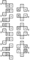
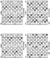
도 6 내지 도 8은 본 발명의 일 실시 예에 따른 RS 밀도(density)의 예들을 도시한 도면이고, 도 9 내지 도 14는 본 발명의 일 실시 예에 따른 RS 패턴의 예들을 도시한 도면이고, 도 15는 본 발명의 일 실시 예에 따른 다중 셀 협동 RS 디자인의 예들을 도시한 도면이다. FIGS. 6 to 8 show examples of RS density according to an embodiment of the present invention, FIGS. 9 to 14 show examples of RS patterns according to an embodiment of the present invention , Figure 15 is a diagram illustrating examples of a multi-cell collaborative RS design in accordance with an embodiment of the present invention.
본 발명의 일 실시 예에 따르면, 간섭 인지 RS 패턴 빌딩 블록을 생성할 수 있다. 이때, 필터에 따른 RS 위치 가능 영역(RS position candidate region)을 설정할 수 있다. 즉, 각 셀 별로 선택된 필터에 따라서 간섭량을 고려하여 다른 RS가 배치될 수 있는 위치가 결정될 수 있다. According to an embodiment of the present invention, an interference or RS pattern building block may be generated. At this time, an RS position candidate region according to the filter can be set. That is, the positions where other RSs can be arranged can be determined in consideration of the amount of interference according to the filter selected for each cell.
좀 더 자세히 살펴보면, 각각의 셀은 필터들의 세트로 구성될 수 있다. 예를 들면 각각의 필터는 간섭에 강한 것, 약한 것, 중간인 것 등이 있을 수 있다. 이러한 필터의 세트를 CRS_filter_set 라고 정의할 수 있고, CRS_filter_set = {f1, f2, f3}와 같이 표현할 수 있다. 이때, 예를 들면 간섭량이 많은 순서로 f1<f2<f3와 같을 수 있다. 이러한 필터의 간섭량이 많은 정도는 오퍼레이터(operator)가 정할 수 있다. Looking more closely, each cell can consist of a set of filters. For example, each filter may be strong, weak, or medium interference. A set of such filters can be defined as CRS_filter_set, and CRS_filter_set = {f1, f2, f3}. At this time, for example, f1 < f2 < f3 may be equal to the order of interference. The degree of interference of these filters can be determined by the operator.
한편, 간섭 임계치(threshold)(t)에 대하여 정의할 수 있다. 이러한 간섭 임계치는 동작에 대한 평가, 시스템의 요구 조건, 또는 간섭 한계 요구 조건 등에 따라 정의할 수 있다. 간섭 임계치의 목적은 시간-주파수 도메인 상에서 필터가 얼마나 많은 간섭을 발생시키는지 여부를 평가하기 위한 것이다. On the other hand, an interference threshold (t) can be defined. Such an interference threshold may be defined according to an evaluation of the operation, a requirement of the system, or an interference limit requirement. The purpose of the interference threshold is to evaluate how much interference the filter causes on the time-frequency domain.
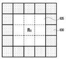
예를 들면, 간섭 임계치(t)는 t1, t2, t3의 3 개의 값을 가질 수 있다. 이때, 시간-주파수 도메인 상에서 필터가 얼마나 많은 간섭을 발생시키는지 여부에 대한 간섭 값은 RS의 주변 위치에 대한 측정을 통해 획득할 수 있다. 예를 들면, 도 6을 참고하면, R0로 표시된 RS의 주변 어두운 영역(610)에 대하여 간섭을 측정하여 그 값을 합한 값을 제1 간섭 값(f1)으로 정할 수 있다. 즉, 제1 간섭 값(f1)은 R0를 (0, 0)으로 표현한 경우 (0, 1), (0, -1), (1, 0), (-1, 0) 영역의 간섭을 합한 값일 수 있다. 그리고 제1 간섭 가능 영역(610)에 대한 제1 간섭 값(f1)이 제1 간섭 임계치(t1)보다 작은지 여부를 판단할 수 있다. 그 결과 제1 간섭 값(f1)이 제1 간섭 임계치(t1)보다 작은 경우(f1<t1)(또는 f1≤t1), 그 필터는 제1 필터 클래스(filter class)(또는 필터 클래스 1)로 정의할 수 있다. 한편, 상기 "필터 클래스"라는 용어는 "RS 밀도(density)" 등과 같은 용어로 사용될 수도 있으며, 이는 필터의 특성에 따라 RS의 배치 정도가 달라짐을 나타내기 위한 것으로 그 용어는 제한되지 않는다. 다만 설명의 편의를 위해 필터 클래스라는 용어를 사용하기로 한다. For example, the interference threshold value t may have three values t1, t2, and t3. At this time, the interference value for how much interference the filter generates on the time-frequency domain can be obtained by measuring the peripheral position of the RS. For example, referring to FIG. 6, a value obtained by measuring the interference with respect to the peripheral
유사하게, R0를 기준으로 그 주변 영역 (1, 0), (1, 1), (0, 1), (-1, 1), (-1, 0), (-1, -1), (0, -1), (-1, -1)의 영역의 간섭을 합한 값을 제2 간섭 값(f2)으로 정할 수 있다. 그리고 제2 간섭 값(f2)이 제1 간섭 임계치(t1) 이상이고, 제2 간섭 임계치(t2)보다 작은 경우(t1≤f2<t2)(실시 예에 따라 f2는 t1 보다 클 수도 있고 또는 f2는 t2 이하일 수도 있다), 그 필터는 제2 필터 클래스(또는 필터 클래스 2)로 정의할 수 있다. 그리고 R0를 기준으로 그 주변 영역 (1, 0), (1, 1), (0, 1), (-1, 1), (-1, 0), (-1, -1), (0, -1), (-1, -1), (2, 0), (2, 1), (2, 2), (1, 2), (1, 2), (0, 2), (-1, 2), (-2, 2), (-2, 1), (-2, 0), (-2, -1), (-2, -2), (-1, -2), (0, -2), (1, -2), (2, -2)의 영역의 간섭을 합한 값을 제3 간섭 값(f3)으로 정할 수 있다. 그리고 제3 간섭 값(f3)이 제2 간섭 임계치(t2) 이상이고, 제3 간섭 임계치(t3)보다 작은 경우(t2≤f3<t3)(실시 예에 따라 f3는 t2 보다 클 수도 있고 또는 f3는 t3 이하일 수도 있다), 그 필터는 제3 필터 클래스(또는 필터 클래스 3)로 정의할 수 있다. 그리고, 그리고 제3 간섭 값(f3)이 제3 간섭 임계치(t3) 이상인 경우(t3≤f3)(또는 t3<f3)인 경우 그 필터는 제4 필터 클래스(또는 필터 클래스 4)로 정의할 수 있다. 이상은 일 예에 불과하고, 이와 유사하게 제5 필터 클래스, 제6 필터 클래스, 제n 필터 클래스 등이 정의될 수도 있음은 물론이다. Similarly, the neighboring regions (1, 0), (1, 1), (0,1), (-1,1), (-1,0) (0, -1) and (-1, -1) can be defined as the second interference value f2. If the second interference value f2 is greater than or equal to the first interference threshold t1 and smaller than the second interference threshold t2 (t1? F2 <t2) (f2 may be greater than t1 or f2 May be less than or equal to t2), and the filter may be defined as a second filter class (or filter class 2). (0, 1), (-1, 1), (-1, 0), (-1, -1), (0) , -1, -1, -1, 2, 0, 2, 1, 2, 1, 2, -1, -2), (-2, -2), (-2, 1), (-2, 0) A value obtained by adding the interference of the regions of (0, -2), (1, -2), and (2, -2) to the third interference value f3. If the third interference value f3 is greater than or equal to the second interference threshold t2 and smaller than the third interference threshold t3 (t2? F3 <t3) (f3 may be greater than t2 or f3 May be equal to or less than t3), and the filter may be defined as a third filter class (or filter class 3). If the third interference value f3 is equal to or higher than the third interference threshold value t3 (t3? F3) (or t3 <f3), the filter can be defined as a fourth filter class (or filter class 4) have. The above is merely an example, and it goes without saying that the fifth filter class, the sixth filter class, the nth filter class, and the like may be similarly defined.
이와 같은 경우 필터에 따른 RS 위치 가능 영역(RS position candidate region)을 필터 클래스에 따라 결정할 수 있다. 즉, 필터의 간섭 값에 따라서 그 RS 위치 가능 영역을 설정할 수 있다. In this case, the RS position candidate region according to the filter can be determined according to the filter class. That is, the RS positionable area can be set in accordance with the interference value of the filter.
예를 들면, 도 6을 참고하면, 제1 필터 클래스인 경우에 도시된 바와 같이 어두운 영역(610)은 RS 위치 가능 영역이 될 수 있다. 즉, 제1 RS 위치 가능 영역(P1)은 R0를 (0, 0)으로 표현한 경우, P1 = { (0,1), (1,0), (-1,0), (0,-1) }와 같을 수 있다. For example, referring to FIG. 6, the
그리고 필터가 제2 필터 클래스인 경우에 도 7에 도시된 바와 같은 어두운 영역(620)은 RS 위치 가능 영역이 될 수 있다. 즉, 필터가 제2 필터 클래스인 경우에 R0의 주변에 간섭 가능 영역(625)이 위치하므로, 그와 벗어난 제2 RS 위치 가능 영역(P2)가 위치할 수 있다. 즉, 제2 RS 위치 가능 영역(P2)은 P2 = { (1,1), (-1,1), (-1,-1), (1,-1) }와 같을 수 있다. And when the filter is the second filter class, the
그리고, 필터가 제3 필터 클래스인 경우에는 도 8에 도시된 바와 같은 어두운 영역(630)이 RS 위치 가능 영역이 될 수 있다. 이 경우에는 R0 주변의 간섭 가능 영역(635)을 벗어난 영역에 제3 RS 위치 가능 영역(P3)가 위치할 수 있다. 즉, 제3 RS 위치 가능 영역(P3)은 P3 = { (2,0), (2,1), (2,2), (1,2), (0,2), (-1,2), (-2,2), (-2,1), (-2,0), (-2,-1), (-2,-2), (-1,-2), (0,-2), (1,-2), (2,-2), (2,-1) }와 같을 수 있다. 유사하게, 도시되지 않았지만 필터가 제4 필터 클래스인 경우에는 제4 RS 위치 가능 영역(P4)은 P4 = { (3,0), (3,1), (3,2), (3,3), (2,3), (1,3), (0,3), (-1,3), (-2,3), (-3,3), (-3,2), (-3,1), (-3,0), (-3,-1), (-3,-2), (-3,-3), (-2,-3), (-1,-3), (0,-3), (1,-3), (2,-3), (3,-3), (3,-2), (3,-1) }와 같을 수 있다. If the filter is the third filter class, the
한편, 멀티 셀(multi cell) 환경, 예를 들면 공동 멀티포인트(CoMP: coordinative multipoint)의 경우에는 N 개의 복수 개의 셀이 협동할 수 있다. 이러한 경우에 각각의 셀은 RS(특히 CRS) 전송을 위하여 동일한 필터의 세트(f1, f2, ..., fk)(2≤k)를 사용할 수 있다. 이때, 셀 i(cell i)가 사용하는 필터를 Fi라 표현할 수 있다. 예를 들면 셀 1이 f2 필터를 사용하는 경우에 F1 = f2라 표현할 수 있다. 그리고 셀 i의 필터 클래스는 Gi라 표현할 수 있다. 예를 들면, 셀 1이 f2 필터를 사용하고, 이때 필터 클래스는 1인 경우 F1 = f2, G1 = 1 과 같이 표현할 수 있다. Meanwhile, in the case of a multi-cell environment, for example, a co-ordinated multipoint (CoMP), a plurality of N cells can cooperate. In this case, each cell may use the same set of filters (f1, f2, ..., fk) (2? K) for RS (especially CRS) transmissions. At this time, the filter used by cell i (cell i) can be expressed as Fi. For example, when
이와 같은 경우에, RS 패턴 빌딩 블록(또는 CRS 패턴 빌딩 블록) 생성 알고리즘은 셀 1(제1 셀)로부터 시작하고, 제2 셀, 제3 셀 등으로 진행하면서 만들 수 있다. RS 패턴 빌딩 블록 알고리즘은 제1 셀의 RS(또는 CRS)로부터 다른 셀의 RS의 상대적인 위치를 결정하는 것이다. In this case, the RS pattern building block (or CRS pattern building block) generating algorithm may be generated starting from cell 1 (the first cell), proceeding to the second cell, the third cell, and the like. The RS pattern building block algorithm determines the relative location of the RSs of the other cells from the RSs (or CRSs) of the first cell.
CRS 패턴 빌딩 블록 생성 알고리즘에 대해서 살펴보면, 먼저 제1 셀의 CRS 위치(CRS_BLK)를 (0, 0)으로 정할 수 있다. 이는 제1 셀의 RE 위치로 하나의 블록만을 포함한다. 그리고, m = 1 부터 N까지 각각의 셀의 CRS 위치를 결정할 수 있다. 이에 대한 절차는 다음 [표 1]과 같을 수 있다. Referring to the CRS pattern building block generation algorithm, the CRS location (CRS_BLK) of the first cell can be set to (0, 0). This includes only one block at the RE position of the first cell. Then, the CRS position of each cell from m = 1 to N can be determined. The procedure for this can be as shown in [Table 1].
For each element in CRS_BLK:
For k = 1 to m-1
If Gk < Gm+1 then the RE positions in interference region less than Gm+1 are eliminated.
If Gk >= Gm+1 then the RE positions in interference region less than Gk are eliminated.
End
The RE positions that are not eliminated are appended to the element
EndFor m = 1 to N
For each element in CRS_BLK:
For k = 1 to m-1
If Gk <Gm + 1 then the RE positions in the interference region are less than Gm + 1 are eliminated.
If Gk> = Gm + 1 then the RE positions in the interference region are less than Gk are eliminated.
End
The RE positions have been added to the element
End
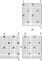
예를 들면, 도 9 및 도 10을 참고하면, 제1 셀, 제2 셀 및 제3 셀이 존재하고 상기 셀들의 필터 클래스가 모두 필터 클래스 1인 경우(G1 = 1, G2 = 1, G3 = 1)에 기지국은 CRS 패턴 블록을 결정할 수 있다. 즉, 기지국은 셀 ID와 필터 클래스를 이용하여 CRS 패턴을 결정할 수 있다. 이때, 기준인 셀의 필터 클래스가 x인 경우에, 나머지 셀의 CRS 배치 가능 위치는 x보다 크거나 같은 RS 위치 가능 영역이 될 수 있다. 예를 들면, 제1 셀을 기준으로 하는 경우 제1 셀의 필터 클래스가 1이므로, 제2 셀 및 제3 셀의 CRS 배치 가능 위치는 제1 CRS 위치 가능 영역, 제2 CRS 위치 가능 영역, 제3 CRS 위치 가능 영역 등일 수 있다. 마찬가지로, 제2 셀을 기준으로 하는 경우에도 제2 셀의 필터 클래스가 1이므로 제3 셀 및 제1 셀의 CRS 배치 가능 영역은 제1, 제2, 제3 CRS 위치 가능 영역 등일 수 있다. 그리고 제3 셀을 기준으로 하는 경우에도 제3 셀의 필터 클래스가 1이므로 제1 셀 및 제3 셀의 CRS 배치 가능 영역은 제1, 제2, 제3 CRS 위치 가능 영역 등일 수 있다. 이에 따라서 기지국은 가장 컴팩트(compact)한 패턴을 결정할 수 있다. 그리고 그 결정된 패턴을 단말에게 전송할 수 있다(broadcast). For example, referring to FIG. 9 and FIG. 10, when the first cell, the second cell, and the third cell exist and all the filter classes of the cells are the filter class 1 (G1 = 1, G2 = 1, G3 = 1), the base station can determine the CRS pattern block. That is, the BS can determine the CRS pattern using the cell ID and the filter class. At this time, when the filter class of the reference cell is x, the CRS positionable position of the remaining cells can be an RS locatable region equal to or greater than x. For example, when the first cell is used as a reference, the filter class of the first cell is 1, so that the CRS positionable area of the second cell and the third cell is the first CRS position enable area, the second CRS position enable area, 3 CRS positionable area, and the like. Likewise, even when the second cell is used as a reference, the CRS allocatable region of the third cell and the first cell can be the first, second, and third CRS positionable regions and the like because the filter class of the second cell is 1. Also, even when the third cell is used as the reference, since the filter class of the third cell is 1, the CRS allocatable region of the first cell and the third cell can be the first, second, and third CRS positionable regions. Accordingly, the base station can determine the most compact pattern. Then, the determined pattern can be transmitted to the terminal.
도 9를 참고하면, 제1 셀 내지 제3 셀의 필터 클래스가 1이므로, 가능한 CRS 위치 가능 영역은 제1 내지 제n CRS 위치 가능 영역이 될 수 있다. 이 경우에는 제1 CRS 위치 가능 영역이 가장 단순한 것으로 기지국은 이에 따라 제1 내지 제3 셀의 CRS를 배치하도록 결정할 수 있다. 즉, 도 9에 도시된 바와 같이 910, 920, 930과 같이 제1 셀 내지 제3 셀의 CRS가 서로 일렬로 수직하게 배치되는 것이 가장 컴팩트할 수 있다. 그러나, 도 10에 도시된 1010의 경우에는 일렬로 배치된 것으로 가능하지만 시간 자원이 제한되므로 가장 컴팩트한 것은 아니다. 또한 1020의 경우에는 제1 셀의 CRS와 제3 셀의 CRS가 제1 CRS 위치 가능 영역에 있는 것이 아니므로 가장 컴팩트한 것이 아니다. Referring to FIG. 9, since the filter classes of the first cell to the third cell are 1, the possible CRS positionable areas may be the first to nth CRS positionable areas. In this case, the first CRS locatable area is the simplest and the base station can accordingly determine to place the CRS of the first through third cells. That is, as shown in FIG. 9, it can be most compact that the CRSs of the first cell to the third cell are arranged vertically in a line, such as 910, 920 and 930. However, in the case of 1010 shown in FIG. 10, it is possible to arrange them in a line, but it is not the most compact because time resources are limited. Also, in the case of 1020, since the CRS of the first cell and the CRS of the third cell are not located in the first CRS position enable area, they are not the most compact.
도 11 및 도 12를 참고하면, 제1 셀, 제2 셀 및 제3 셀이 존재하고 상기 셀들의 필터 클래스가 모두 필터 클래스 2인 경우(G1 = 2, G2 = 2, G3 = 2)에 기지국은 CRS 패턴 블록을 결정할 수 있다. 이때, 제1 셀을 기준으로 하는 경우 제1 셀의 필터 클래스가 2이므로, 제2 셀 및 제3 셀의 CRS 배치 가능 위치는 제2 CRS 위치 가능 영역, 제3 CRS 위치 가능 영역 등일 수 있다. 마찬가지로, 제2 셀을 기준으로 하는 경우에도 제2 셀의 필터 클래스가 2이므로 제3 셀 및 제1 셀의 CRS 배치 가능 영역은 제2, 제3 CRS 위치 가능 영역 등일 수 있다. 그리고 제3 셀을 기준으로 하는 경우에도 제3 셀의 필터 클래스가 2이므로 제1 셀 및 제3 셀의 CRS 배치 가능 영역은 제2, 제3 CRS 위치 가능 영역 등일 수 있다. 이에 따라서 기지국은 가장 컴팩트(compact)한 패턴을 결정할 수 있다. 그리고 그 결정된 패턴을 단말에게 전송할 수 있다(broadcast). 11 and 12, when the first cell, the second cell and the third cell exist and all the filter classes of the cells are filter class 2 (G1 = 2, G2 = 2, G3 = 2) Can determine the CRS pattern block. In this case, when the first cell is used as a reference, the filter class of the first cell is 2, so that the CRS positionable position of the second cell and the third cell can be the second CRS position enable region, the third CRS position enable region, and the like. Likewise, even when the second cell is used as the reference, since the filter class of the second cell is 2, the CRS allocatable region of the third cell and the first cell can be the second and third CRS positionable regions and the like. Also, even when the third cell is used as the reference, since the filter class of the third cell is 2, the CRS allocatable region of the first cell and the third cell can be the second and third CRS positionable regions and the like. Accordingly, the base station can determine the most compact pattern. Then, the determined pattern can be transmitted to the terminal.
도 11을 참고하면, 제1 셀 내지 제3 셀의 필터 클래스가 2이므로, 가능한 CRS 위치 가능 영역은 제2 내지 제n CRS 위치 가능 영역이 될 수 있다. 이 경우에는 제2 CRS 위치 가능 영역이 가장 단순한 것으로 기지국은 이에 따라 제1 내지 제3 셀의 CRS를 배치하도록 결정할 수 있다. 즉, 도 11에 도시된 바와 같이 1110, 1120, 1130, 1140, 1150과 같이 제1 셀 내지 제3 셀의 CRS가 서로 대각선 위치로 배치되는 것이 가장 컴팩트할 수 있다. 그러나, 도 12에 도시된 1210, 1220, 1230, 1240의 경우에는 가장 컴팩트한 것이 아닐 수 있다. Referring to FIG. 11, since the filter classes of the first cell to the third cell are 2, the possible CRS positionable areas may be the second to the n-th CRS positionable areas. In this case, the second CRS locatable area is the simplest and the base station can accordingly determine to place the CRS of the first through third cells. That is, as shown in FIG. 11, it can be most compact that the CRSs of the first cell to the third cell are arranged diagonally with each other like 1110, 1120, 1130, 1140, and 1150. However, in the case of 1210, 1220, 1230 and 1240 shown in FIG. 12, it may not be the most compact.
조금 더 구체적으로 설명하면, 제1 셀을 기준으로 하는 경우에 제2 셀의 CRS 배치 가능 영역을 함께 표현하면 다음과 같을 수 있다. CRS_BLK = { [(0,0), (1,1)] , [(0,0), (1,-1)] , [(0,0), (-1,-1)], [(0,0), (-1,1)] } 그리고, 제3 셀의 CRS 배치 가능 영역을 이에 추가하는 경우에 다음과 같을 수 있다. CRS_BLK = { [ (0,0), (1,1), (1,-1)] , [(0,0), (-1,1), (-1,-1)], [(0,0), (-1,-1),(0,-2)], [(0,0), (1,-1), (0,-2)], [(0,0), (-1,1), (0,2)], [(0,0), (1,1), (0,2)], [(0,0), (1,1), (2,2)], [(0,0), (-1,-1), (-2,-2)], [(0,0), (2,2), (1,1)], [(0,0), (0,2), (2,1)] } 그리고, 기지국은 제3 셀의 CRS 배치 가능 영을 포함한 패턴 중 가장 컴팩트한 패턴을 결정하여 이를 단말에게 알려줄 수 있다. More specifically, when the first cell is used as a reference, the CRS allocatable area of the second cell may be expressed as follows. CRS_BLK = {[(0,0), (1,1)], [(0,0), (1, -1)], [ 0,0), (-1,1)]} and the CRS allocatable area of the third cell is added to the following. CRS_BLK = {[(0,0), (1,1), (1,1)], [(0,0), (-1,1), , (0, 0), (0, 0), (0, -2) (0,0), (1,1), (0,2)], [(0,0), (1,1), (2,2 ), [(0,0), (-1, -1), (-2, -2)], [(0,0), (2,2), , 0), (0, 2), (2, 1)]} and the base station can determine the most compact pattern among the patterns including the CRS allocatable zero of the third cell and inform the UE of the most compact pattern.
도 13 및 도 14를 참고하면, 제1 셀, 제2 셀 및 제3 셀이 존재하고 상기 제1 셀 및 제3 셀의 필터 클래스는 1이고, 제2 셀의 필터 클래스는 필터 클래스 2인 경우(G1 = 1, G2 = 2, G3 = 1)에 기지국은 CRS 패턴 블록을 결정할 수 있다. 이때, 제1 셀을 기준으로 하는 경우 제1 셀의 필터 클래스가 1이므로, 제2 셀 및 제3 셀의 CRS 배치 가능 위치는 제1 CRS 위치 가능 영역, 제2 CRS 위치 가능 영역, 제3 CRS 위치 가능 영역 등일 수 있다. 반면, 제2 셀을 기준으로 하는 경우에 제2 셀의 필터 클래스가 2이므로, 제3 셀 및 제1 셀의 CRS 배치 가능 영역은 제2, 제3 CRS 위치 가능 영역 등일 수 있다. 그리고 제3 셀을 기준으로 하는 경우에는 제3 셀의 필터 클래스가 1이므로 제1 셀 및 제3 셀의 CRS 배치 가능 영역은 제1, 제2, 제3 CRS 위치 가능 영역 등일 수 있다. 이에 따라서 기지국은 가장 컴팩트(compact)한 패턴을 결정할 수 있다. 그리고 그 결정된 패턴을 단말에게 전송할 수 있다(broadcast). 13 and 14, there is a first cell, a second cell and a third cell, a filter class of the first cell and a third cell is 1, and a filter class of the second cell is a
도 13을 참고하면, 제1 셀 및 제3 셀의 필터 클래스는 1이고, 제2 셀의 필터 클래스는 필터 클래스 2이므로, 가능한 CRS 위치 가능 영역은 필터 클래스에 따라서 결정할 수 있다. 이에 따라서 결정된 CRS의 가능한 위치는 도 13에 도시된 바와 같이 1310, 1315, 1320, 1325, 1330 ,1335, 1340 ,1345, 1350 ,1355 ,1360 ,1365, 1370, 1375와 같을 수 있다. 그러나, 도 14에 도시된 1410, 1420, 1430, 1440, 1450, 1460의 경우에는 가장 컴팩트한 것이 아닐 수 있다.Referring to FIG. 13, since the filter class of the first cell and the third cell is 1 and the filter class of the second cell is the
도 15는 본 발명의 일 실시 예에 따른 다중 셀 협동 RS 디자인의 예들을 도시한 도면이다. 15 is a diagram illustrating examples of a multi-cell collaborative RS design in accordance with an embodiment of the present invention.
이상에서는, RS 패턴 빌딩 블록을 생성하는 방법에 대하여 살펴보았다.In the above, a method of generating an RS pattern building block has been described.
이하에서는, 생성된 RS 패턴 빌딩 블록을 이용하여 RS 패턴을 구성하는 방법에 대하여 살펴보도록 한다. Hereinafter, a method of constructing an RS pattern using the generated RS pattern building block will be described.
도 16 및 도 17은 본 발명의 일 실시 예에 따른 RS 패턴 빌딩 블록을 생성하는 방법을 도시한 도면이고, 도 18 내지 도 20은 본 발명의 일 실시 예에 따른 RS 패턴의 배치의 예들을 도시한 도면이다. FIGS. 16 and 17 show a method of generating an RS pattern building block according to an embodiment of the present invention. FIGS. 18 to 20 show examples of the arrangement of RS patterns according to an embodiment of the present invention. Fig.
도 16을 참고하면, RS 패턴 빌딩 블록을 이용하여 RS 패턴을 구성할 수 있다. 이 경우 RS 패턴 구성은 셀 식별자, 필터 클래스 식별자, RB 사이즈 등을 이용하여 결정될 수 있다. 즉 도 16에서 1610으로 나타낸 것과 같이, 결정된 RS 패턴 빌딩 블록을 시간 및 주파수 축 상에서 얼만큼 쉬프트(shift) 시켜 배치할 것인지를 결정할 수 있다. 종래의 경우에는 하나의 RE의 주파수 쉬프트만 허용되었었지만, FBMC 시나리오의 경우, 필터들이 사용됨으로 인해서 주파수 서브캐리어들이 더 이상 수직이 아니므로 필터 클래스에 따라서 다중 주파수 쉬프트 및/또는 시간 쉬프트가 가능할 수 있다. Referring to FIG. 16, an RS pattern can be configured using an RS pattern building block. In this case, the RS pattern configuration can be determined using a cell identifier, a filter class identifier, an RB size, and the like. That is, as indicated by 1610 in FIG. 16, it can be determined how much to shift the determined RS pattern building block on the time and frequency axes. In the FBMC scenario, the frequency subcarriers are no longer vertical due to the use of filters, so that multiple frequency shifts and / or time shifts may be possible depending on the filter class, although only one RE frequency shift was allowed in the prior art have.
이때, RS 패턴을 구성하는 경우에 다음과 같은 사항을 고려할 수 있다. 자원 영역에서 특정 주파수 및 시간 쉬프트는 셀 식별자(cell id)에 따라 결정될 수 있다. 또한 다중 안테나의 집적된 특성(nested property)을 고려하고, 안테나 포트들 및 이웃 셀들의 RS(CRS)는 서로 겹치지 않아야 한다. 그리고 안테나 포트들 및 이웃 셀들의 RS(CRS)는 간섭이 강한 영역에 배치되어서는 안 된다. At this time, when constructing the RS pattern, the following matters can be considered. The specific frequency and time shift in the resource region may be determined according to the cell identifier. Also, considering the nested properties of multiple antennas, the antenna ports and the neighboring cells' RSs (CRS) should not overlap. And the antenna ports and neighboring cells' RSs (CRS) should not be placed in areas with strong interference.
때문에, 도 16에 도시된 바와 같이 다른 셀의 RS가 겹치지 않도록 시간 및 주파수 축 상에서 쉬프트하여 RS 패턴 빌딩 블록을 배치할 수 있다. Therefore, as shown in FIG. 16, it is possible to arrange the RS pattern building blocks by shifting on the time and frequency axes so that the RSs of other cells do not overlap.
또한 도 17을 참고하면, 도 13에 예시된 제1 셀, 제2 셀 및 제3 셀이 존재하고 상기 제1 셀 및 제3 셀의 필터 클래스는 1이고, 제2 셀의 필터 클래스는 필터 클래스 2인 경우(G1 = 1, G2 = 2, G3 = 1)에 RS 패턴을 구성하는 방법에 대하여 도시하고 있다. 이때, 제0 안테나 포트의 제0 RS 패턴 빌딩 블록(1710)과 제1 안테나 포트의 제1 RS 패턴 빌딩 블록(1720)이 도시된 바와 같이 구성되는 경우, 제0 RS 패턴 빌딩 블록(1710)의 제2 셀의 RS는 제1 RS 패턴 빌딩 블록(1720)의 제1 셀의 RS의 간섭이 강한 영역에 배치된다. 또한, 제1 RS 패턴 빌딩 블록(1720)의 제1 셀의 RS는 제0 RS 패턴 빌딩 블록(1710)의 제2 셀의 RS의 간섭이 강한 영역에 배치되는 것으로 볼 수도 있다. Referring to FIG. 17, the first cell, the second cell, and the third cell illustrated in FIG. 13 exist, the filter class of the first cell and the third cell is 1, 2 (G1 = 1, G2 = 2, G3 = 1). When the 0th RS
즉, RS 패턴 빌딩 블록 간 거리를 결정한 후에, 안테나 포트 별로 RS 패턴 빌딩 블록들을 배치하고, 이 안테나 포트 별 RS 패턴은 겹치지 않도록 배치하여야 한다(간섭이 강한 영역에 배치되지 않도록 하는 것 포함). That is, after determining the distance between the RS pattern building blocks, RS pattern building blocks are arranged for each antenna port, and the RS patterns for each antenna port are arranged so as not to overlap (including not to be placed in a region where interference is strong).
이때, 시간 축 쉬프트 값과 주파수 축 쉬프트 값은 다음 [수학식 1]과 같이 정의할 수도 있다. In this case, the time-axis shift value and the frequency-axis shift value may be defined as the following Equation (1).
[수학식 1][Equation 1]
Tshift = Function (cell location ID, cell ID, RB size, filter class)T shift = Function (cell location ID, cell ID, RB size, filter class)
Fshift = Function (cell location ID, cell ID, RB size, filter class)F shift = Function (cell location ID, cell ID, RB size, filter class)
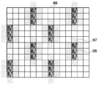
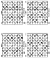
도 18 내지 도 20은 RB 사이즈가 7이고, 제1 셀, 제2 셀 및 제3 셀의 필터 클래스가 모두 2인 경우의 RS 패턴 구성에 대하여 도시한 도면이다. 이를 참고하면, 다음 [표 2]에 도시된 바에 따라 시간 및 주파수 쉬프트가 계산될 수 있다. Figs. 18 to 20 are diagrams showing the RS pattern configuration when the RB size is 7 and the filter classes of the first cell, the second cell, and the third cell are all 2s. With reference to this, the time and frequency shifts can be calculated as shown in the following [Table 2].
[표 2][Table 2]

도 18을 참고하면, 안테나 포트가 하나인 경우에 RS 패턴의 구성은 1810과 같을 수 있다. 그리고 도 19을 참고하면 안테나 포트가 두 개인 경우에는 RS 패턴의 구성은 제1 안테나 포트 및 제2 안테나 포트에 대하여 각각 1910 및 1920과 같을 수 있다. 그리고 안테나 포트가 네 개인 경우에는 RS 패턴의 구성은 제1 내지 제4 안테나 포트에 대하여 각각 2010, 2020, 2030, 2040과 같을 수 있다. Referring to FIG. 18, in the case of one antenna port, the configuration of the RS pattern may be the same as 1810. Referring to FIG. 19, if there are two antenna ports, the configuration of the RS pattern may be equal to 1910 and 1920 for the first antenna port and the second antenna port, respectively. If there are four antenna ports, the configuration of the RS pattern may be equal to 2010, 2020, 2030, and 2040 for the first to fourth antenna ports, respectively.
이상에서는, 생성된 RS 패턴 빌딩 블록을 이용하여 RS 패턴을 구성하는 방법에 대하여 살펴보았다. In the foregoing, a method of constructing an RS pattern using the generated RS pattern building block has been described.
이상에서는 본 발명에 따른 경우에 효율에 대하여 살펴보도록 한다.The efficiency of the present invention will now be described.
도 21은 RS의 주변 영역의 간섭 량의 일 예에 대하여 도시한 도면이고, 도 22 내지 도 24는 본 발명의 일 실시 예에 따른 경우에 효율에 대하여 설명하기 위한 도면이다. FIG. 21 is a diagram showing an example of the amount of interference of the peripheral region of the RS, and FIGS. 22 to 24 are diagrams for explaining efficiency in the case of an embodiment of the present invention.
도 21을 참고하면, CRS(2110)는 이웃 데이터 심볼들에 비하여 강한 전력으로 전송된다. 이로 인해 RS 신호로 인한 간섭은 데이터 심볼에 주 간섭원으로 작용한다. Referring to FIG. 21,
이때, 도 22에 도시된 바와 같이 종래 기술에 따라 RS를 배치한 경우 RS에 미치는 간섭 량 Interf는 0.0768 P(= 0.242*4/3)와 같을 수 있다. 반면, 도 23에 도시된 바와 같이 본원 발명의 일 실시 예에 따라 RS를 배치한 경우에는 RS에 미치는 간섭 량 Interf는 0.0588 P(= 0.212*4/3)와 같을 수 있다. 이는 종래 기술에 비하여 23.43% 간섭 량이 줄어든 것임을 확인할 수 있다. At this time, as shown in FIG. 22, when the RS is arranged according to the related art, the interference amount Interf on the RS may be equal to 0.0768 P (= 0.24 2 * 4/3). On the other hand, when RS is arranged according to an embodiment of the present invention as shown in FIG. 23, the interference amount Interf on RS may be equal to 0.0588 P (= 0.21 2 * 4/3). It can be confirmed that the interference amount is reduced by 23.43% compared to the conventional art.
유사하게, 도 23에 도시된 종래 기술에 따른 4포트 안테나에서의 RS에 미치는 간섭 량 Interf는 0.3147 P(= ((0.242+0.562+0.242)*40 + (0.242+0.242)*20 + (0.242+0.562)*8 +0.242*4)/72)와 같을 수 있다. 그러나, 도 24에 도시된 바와 같이 본원 발명의 일 실시 예에 따라 RS를 배치한 경우에는 RS에 미치는 간섭 량 Interf는 0.0588 P(= 0.212*4/3)과 같을 수 있다. 그리고 이는 종래 기술에 비하여 81.32% 간섭 량이 줄어든 것임을 확인할 수 있다. Similarly, the interference amount Interf on the RS in the 4-port antenna according to the prior art shown in FIG. 23 is 0.3147 P (= ((0.24 2 +0.56 2 +0.24 2 ) * 40 + (0.24 2 +0.24 2 ) 20 + (0.24 2 +0.56 2 ) * 8 +0.24 2 * 4) / 72. However, as shown in FIG. 24, when the RS is arranged according to an embodiment of the present invention, the interference amount Interf on the RS may be equal to 0.0588 P (= 0.21 2 * 4/3). It can be confirmed that the interference amount is reduced by 81.32% as compared with the prior art.
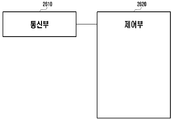
도 25는 본 발명의 일 실시 예에 따른 기지국의 블록 구성도를 도시한 도면이다. 25 is a block diagram of a base station according to an embodiment of the present invention.
도 25를 참고하면, 본 발명의 일 실시 예에 따른 기지국은 통신부(2510) 및 기지국의 전반적인 동작을 제어하는 제어부(2520)를 포함할 수 있다. Referring to FIG. 25, a base station according to an embodiment of the present invention may include a
상기 기지국의 제어부(2520)는 상술한 실시예들 중 어느 하나의 동작을 수행하도록 기지국을 제어한다. 예를 들면, 복수의 셀들의 필터 정보에 따라 상기 복수의 셀들의 기준 신호(RS: reference signal) 패턴 빌딩 블록을 결정하고, 상기 결정된 RS 패턴 빌딩 블록 및 자원 블록(RB: resource block) 크기(size)를 이용하여 상기 복수의 셀들의 RS 패턴을 결정하고, 상기 결정된 RS 패턴에 대한 정보를 단말에게 전송하도록 제어할 수 있다. The
또한, 기지국의 통신부(2510)는 상술한 실시예들 중 어느 하나의 동작에 따라 신호를 송수신한다.In addition, the
도 26은 본 발명의 일 실시 예에 따른 단말의 블록 구성도를 도시한 도면이다. 26 is a block diagram of a terminal according to an embodiment of the present invention.
도 26을 참고하면, 본 발명의 일 실시 예에 따른 단말은 통신부(2610) 및 단말의 전반적인 동작을 제어하는 제어부(2620)를 포함할 수 있다. Referring to FIG. 26, a terminal according to an embodiment of the present invention may include a
상기 단말의 제어부(2620)는 상술한 실시예들 중 어느 하나의 동작을 수행하도록 단말을 제어한다. 예를 들면, 기지국으로부터 복수의 셀들의 기준 신호(RS: reference signal) 패턴에 대한 정보를 수신하고, 상기 수신한 RS 패턴에 대한 정보를 이용하여 RS를 수신하도록 제어할 수 있다. The
또한, 단말의 통신부(2610)는 상술한 실시예들 중 어느 하나의 동작에 따라 신호를 송수신한다. In addition, the
본 명세서와 도면에 개시된 실시 예는 기술 내용을 쉽게 설명하고, 이해를 돕기 위해 특정 예를 제시한 것일 뿐이며, 본 발명의 범위를 한정하고자 하는 것은 아니다. 여기에 개시된 실시 예들 이외에도 본 발명의 기술적 사상에 바탕을 둔 다른 변형 예들이 실시 가능하다는 것은 본 발명이 속하는 기술 분야에서 통상의 지식을 가진 자에게 자명한 것이다.The embodiments disclosed in the present specification and drawings are merely illustrative of specific examples for the purpose of easy explanation and understanding, and are not intended to limit the scope of the present invention. It is to be understood by those skilled in the art that other modifications based on the technical idea of the present invention are possible in addition to the embodiments disclosed herein.
한편, 본 명세서와 도면에는 본 발명의 바람직한 실시 예에 대하여 개시하였으며, 비록 특정 용어들이 사용되었으나, 이는 단지 본 발명의 기술 내용을 쉽게 설명하고 발명의 이해를 돕기 위한 일반적인 의미에서 사용된 것이지, 본 발명의 범위를 한정하고자 하는 것은 아니다. 여기에 개시된 실시 예 외에도 본 발명의 기술적 사상에 바탕을 둔 다른 변형 예들이 실시 가능하다는 것은 본 발명이 속하는 기술 분야에서 통상의 지식을 가진 자에게 자명한 것이다.While the present invention has been particularly shown and described with reference to exemplary embodiments thereof, it is to be understood that the invention is not limited to the disclosed embodiments, but, on the contrary, And is not intended to limit the scope of the invention. It is to be understood by those skilled in the art that other modifications based on the technical idea of the present invention are possible in addition to the embodiments disclosed herein.
610, 620, 630: RS 위치 가능 영역
625, 635: 간섭 영역610, 620, 630: RS positionable area
625, 635: Interference area
Claims (15)
복수의 셀들의 필터 정보에 따라 상기 복수의 셀들의 기준 신호(RS: reference signal) 패턴 빌딩 블록을 결정하는 단계;
상기 결정된 RS 패턴 빌딩 블록 및 자원 블록(RB: resource block) 크기(size)를 이용하여 상기 복수의 셀들의 RS 패턴을 결정하는 단계; 및
상기 결정된 RS 패턴에 대한 정보를 단말에게 전송하는 단계;
를 포함하는 기지국의 통신 방법.A communication method of a base station,
Determining a reference signal (RS) pattern building block of the plurality of cells according to filter information of a plurality of cells;
Determining an RS pattern of the plurality of cells using the determined RS pattern building block and a resource block size; And
Transmitting information on the determined RS pattern to a mobile station;
And a base station.
상기 복수의 셀들의 필터의 간섭량과 미리 결정된 적어도 하나의 간섭 임계치와 비교하는 단계;
상기 비교 결과에 따라 RS의 배치가 가능한 영역에 대한 정보를 포함한 RS 밀도 정보를 결정하는 단계; 및
상기 RS 밀도 정보를 이용하여 상기 RS 패턴 빌딩 블록을 결정하는 단계;
를 포함하는 것을 특징으로 하는 기지국의 통신 방법. 2. The method of claim 1, wherein determining the RS pattern building block comprises:
Comparing the interference amount of the filter of the plurality of cells with the predetermined at least one interference threshold value;
Determining RS density information including information on an area where the RSs can be arranged according to the comparison result; And
Determining the RS pattern building block using the RS density information;
Wherein the base station comprises a base station.
상기 RS 밀도 정보, 상기 RB 크기 및 셀 식별 정보를 이용하여 상기 RS 패턴을 결정하는 단계;
를 포함하는 것을 특징으로 하는 기지국의 통신 방법. 3. The method of claim 2, wherein determining the RS pattern comprises:
Determining the RS pattern using the RS density information, the RB size, and the cell identification information;
Wherein the base station comprises a base station.
상기 RS 패턴 빌딩 블록 사이의 시간 축 및 주파수 축 중 적어도 하나에서의 쉬프트 값을 결정하는 단계;
를 포함하는 것을 특징으로 하는 기지국의 통신 방법. 2. The method of claim 1, wherein determining the RS pattern comprises:
Determining a shift value in at least one of a time axis and a frequency axis between the RS pattern building blocks;
Wherein the base station comprises a base station.
복수의 안테나 포트가 존재하는 경우, 안테나 포트 별 RS 패턴 빌딩 블록들이 겹치지 않도록 상기 RS 패턴 빌딩 블록을 배치하는 단계;
를 포함하는 것을 특징으로 하는 기지국의 통신 방법. 2. The method of claim 1, wherein determining the RS pattern comprises:
Arranging the RS pattern building blocks so that RS pattern building blocks for respective antenna ports do not overlap when there are a plurality of antenna ports;
Wherein the base station comprises a base station.
기지국으로부터 복수의 셀들의 기준 신호(RS: reference signal) 패턴에 대한 정보를 수신하는 단계; 및
상기 수신한 RS 패턴에 대한 정보를 이용하여 RS를 수신하는 단계;
를 포함하고,
상기 RS 패턴에 대한 정보는, 상기 복수의 셀들의 필터 정보에 따라 결정된 RS 패턴 빌딩 블록 및 자원 블록(RB: resource block) 크기(size)를 이용하여 결정된 것을 특징으로 하는 단말의 통신 방법. A communication method of a terminal,
Receiving information on a reference signal (RS) pattern of a plurality of cells from a base station; And
Receiving an RS using information on the received RS pattern;
Lt; / RTI >
Wherein the information on the RS pattern is determined using an RS pattern building block and a resource block size determined according to filter information of the plurality of cells.
다른 네트워크 엔티티와 통신하는 통신부; 및
복수의 셀들의 필터 정보에 따라 상기 복수의 셀들의 기준 신호(RS: reference signal) 패턴 빌딩 블록을 결정하고, 상기 결정된 RS 패턴 빌딩 블록 및 자원 블록(RB: resource block) 크기(size)를 이용하여 상기 복수의 셀들의 RS 패턴을 결정하고, 상기 결정된 RS 패턴에 대한 정보를 단말에게 전송하도록 제어하는 제어부;
를 포함하는 기지국.In the base station,
A communication unit for communicating with other network entities; And
Determining a reference signal (RS) pattern building block of the plurality of cells according to filter information of a plurality of cells, and using the decided RS pattern building block and a resource block size (RB) A controller for determining an RS pattern of the plurality of cells and transmitting information on the determined RS pattern to the terminal;
/ RTI >
상기 복수의 셀들의 필터의 간섭량과 미리 결정된 적어도 하나의 간섭 임계치와 비교하고, 상기 비교 결과에 따라 RS의 배치가 가능한 영역에 대한 정보를 포함한 RS 밀도 정보를 결정하고, 상기 RS 밀도 정보를 이용하여 상기 RS 패턴 빌딩 블록을 결정하도록 제어하는 것을 특징으로 하는 기지국. 9. The apparatus according to claim 8,
Determining RS density information including information on an area where RSs can be arranged according to a result of the comparison, comparing the interference density of the filter of the plurality of cells with at least one predetermined interference threshold, And determines to determine the RS pattern building block.
상기 RS 밀도 정보, 상기 RB 크기 및 셀 식별 정보를 이용하여 상기 RS 패턴을 결정하도록 제어하는 것을 특징으로 하는 기지국. 10. The apparatus according to claim 9,
And controls the RS pattern to be determined using the RS density information, the RB size, and the cell identification information.
상기 RS 패턴 빌딩 블록 사이의 시간 축 및 주파수 축 중 적어도 하나에서의 쉬프트 값을 결정하도록 제어하는 것을 특징으로 하는 기지국. 9. The apparatus according to claim 8,
And determines a shift value in at least one of a time axis and a frequency axis between the RS pattern building blocks.
복수의 안테나 포트가 존재하는 경우, 안테나 포트 별 RS 패턴 빌딩 블록들이 겹치지 않도록 상기 RS 패턴 빌딩 블록을 배치하도록 제어하는 것을 특징으로 하는 기지국. 9. The apparatus according to claim 8,
And controls to arrange the RS pattern building blocks so that RS pattern building blocks for respective antenna ports do not overlap when a plurality of antenna ports exist.
다른 네트워크 엔티티와 통신하는 통신부; 및
기지국으로부터 복수의 셀들의 기준 신호(RS: reference signal) 패턴에 대한 정보를 수신하고, 상기 수신한 RS 패턴에 대한 정보를 이용하여 RS를 수신하도록 제어하는 제어부;
를 포함하고,
상기 RS 패턴에 대한 정보는, 상기 복수의 셀들의 필터 정보에 따라 결정된 RS 패턴 빌딩 블록 및 자원 블록(RB: resource block) 크기(size)를 이용하여 결정된 것을 특징으로 하는 단말. In the terminal,
A communication unit for communicating with other network entities; And
A control unit receiving information on a reference signal pattern of a plurality of cells from a base station and receiving RS information using information on the received RS pattern;
Lt; / RTI >
Wherein the information on the RS pattern is determined using an RS pattern building block and a resource block size determined according to filter information of the plurality of cells.
Priority Applications (3)
| Application Number | Priority Date | Filing Date | Title |
|---|---|---|---|
| KR1020150032548A KR102294742B1 (en) | 2015-03-09 | 2015-03-09 | Method and apparatus for reference signal pattern design in multicarrier system |
| PCT/KR2016/002231 WO2016144063A1 (en) | 2015-03-09 | 2016-03-07 | Method and apparatus for designing reference signal pattern in multi-cell multi-carrier system |
| US15/505,239 US10158514B2 (en) | 2015-03-09 | 2016-03-07 | Method and apparatus for designing reference signal pattern in multi-cell multi-carrier system |
Applications Claiming Priority (1)
| Application Number | Priority Date | Filing Date | Title |
|---|---|---|---|
| KR1020150032548A KR102294742B1 (en) | 2015-03-09 | 2015-03-09 | Method and apparatus for reference signal pattern design in multicarrier system |
Publications (2)
| Publication Number | Publication Date |
|---|---|
| KR20160108994A true KR20160108994A (en) | 2016-09-21 |
| KR102294742B1 KR102294742B1 (en) | 2021-08-27 |
Family
ID=56879472
Family Applications (1)
| Application Number | Title | Priority Date | Filing Date |
|---|---|---|---|
| KR1020150032548A Expired - Fee Related KR102294742B1 (en) | 2015-03-09 | 2015-03-09 | Method and apparatus for reference signal pattern design in multicarrier system |
Country Status (3)
| Country | Link |
|---|---|
| US (1) | US10158514B2 (en) |
| KR (1) | KR102294742B1 (en) |
| WO (1) | WO2016144063A1 (en) |
Cited By (1)
| Publication number | Priority date | Publication date | Assignee | Title |
|---|---|---|---|---|
| WO2024101462A1 (en) * | 2022-11-07 | 2024-05-16 | 삼성전자 주식회사 | Method and device for performing self-interference cancellation |
Citations (3)
| Publication number | Priority date | Publication date | Assignee | Title |
|---|---|---|---|---|
| KR20120100857A (en) * | 2010-02-07 | 2012-09-12 | 엘지전자 주식회사 | A method for transmitting downlink reference signal in multi-carrier supporting wireless communication system and an apparatus for the same |
| KR20140035255A (en) * | 2012-09-11 | 2014-03-21 | 한국전자통신연구원 | Apparatus for communicating using milimeter wave frequency bandwidth and method for communicating using the milimeter wave frequency bandwidth |
| US20140233437A1 (en) * | 2013-02-19 | 2014-08-21 | Futurewei Technologies, Inc. | Frame Structure for Filter Bank Multi-Carrier (FBMC) Waveforms |
Family Cites Families (3)
| Publication number | Priority date | Publication date | Assignee | Title |
|---|---|---|---|---|
| US8681833B2 (en) * | 2008-04-23 | 2014-03-25 | Sharp Kabushiki Kaisha | Communication system, transmitter, receiver and communication method |
| CN102301797B (en) * | 2009-04-17 | 2015-03-11 | 上海贝尔股份有限公司 | Method, Apparatus and Device for Selecting Relay User and Allocating Downlink Resource |
| WO2016032295A1 (en) * | 2014-08-29 | 2016-03-03 | Samsung Electronics Co., Ltd. | Method and apparatus for channel estimation and equalization in qam-fbmc system |
-
2015
- 2015-03-09 KR KR1020150032548A patent/KR102294742B1/en not_active Expired - Fee Related
-
2016
- 2016-03-07 US US15/505,239 patent/US10158514B2/en active Active
- 2016-03-07 WO PCT/KR2016/002231 patent/WO2016144063A1/en not_active Ceased
Patent Citations (3)
| Publication number | Priority date | Publication date | Assignee | Title |
|---|---|---|---|---|
| KR20120100857A (en) * | 2010-02-07 | 2012-09-12 | 엘지전자 주식회사 | A method for transmitting downlink reference signal in multi-carrier supporting wireless communication system and an apparatus for the same |
| KR20140035255A (en) * | 2012-09-11 | 2014-03-21 | 한국전자통신연구원 | Apparatus for communicating using milimeter wave frequency bandwidth and method for communicating using the milimeter wave frequency bandwidth |
| US20140233437A1 (en) * | 2013-02-19 | 2014-08-21 | Futurewei Technologies, Inc. | Frame Structure for Filter Bank Multi-Carrier (FBMC) Waveforms |
Non-Patent Citations (2)
| Title |
|---|
| Eeva Lahetkangas et al., ‘On the flexible 5G dense deployment air interface for mobile broadband’, In: 5G for Ubiquitous Connectivity (5GU), 2014 1st International Conference on(2014.11.28.) * |
| Yuya Saito et al., ‘Non-Orthogonal Multiple Access (NOMA) for Cellular Future Radio Access’, In: Vehicular Technology Conference (VTC Spring), 2013 IEEE 77th(2013.06.05.) * |
Cited By (1)
| Publication number | Priority date | Publication date | Assignee | Title |
|---|---|---|---|---|
| WO2024101462A1 (en) * | 2022-11-07 | 2024-05-16 | 삼성전자 주식회사 | Method and device for performing self-interference cancellation |
Also Published As
| Publication number | Publication date |
|---|---|
| WO2016144063A1 (en) | 2016-09-15 |
| US10158514B2 (en) | 2018-12-18 |
| KR102294742B1 (en) | 2021-08-27 |
| US20170366378A1 (en) | 2017-12-21 |
Similar Documents
| Publication | Publication Date | Title |
|---|---|---|
| US12328161B2 (en) | Methods and devices for feeding back and configuring pilot parameters, user terminal and base station | |
| KR101701899B1 (en) | 8-transmit antenna reference signal design for downlink communications in a wireless system | |
| US9843942B2 (en) | Device and method of enhancing downlink UE-specific demodulation reference signal to facilitate inter-cell interference cancellation and suppression | |
| US8228862B2 (en) | Method and system for reference signal pattern design | |
| US8432994B2 (en) | Method for determining demodulation reference signal in the uplink, UE and uplink system | |
| US9276729B2 (en) | Determination of a noise and interference covariance measure | |
| KR102228260B1 (en) | Method and apparatus for transmitting and receiving reference signals | |
| CN101771444B (en) | Method for setting reference signals in multi-antenna system and base station | |
| CN108155925B (en) | Method and device in UE and base station for power adjustment | |
| US20190081761A1 (en) | Method and device for sending reference signal | |
| CN110754104A (en) | transmit reference signal information | |
| CN111162806A (en) | A method and system for detecting and eliminating narrowband interference in a wireless broadband system | |
| US10425701B2 (en) | Filter reuse method for transmitting and receiving filter bank-based multicarrier signals | |
| KR20190127911A (en) | Transmitter and receiver | |
| KR20160025389A (en) | Wireless communication system and method for managing resource for interference coordication thereof | |
| CN112073098B (en) | UE supporting synchronization signal, method and device in base station | |
| KR102294742B1 (en) | Method and apparatus for reference signal pattern design in multicarrier system | |
| US10230506B2 (en) | Signal transmission method for inter-cell interference | |
| KR20110127051A (en) | Apparatus and method for processing channel state measurement reference signal in wireless communication system | |
| JP7435838B2 (en) | User equipment and base stations | |
| KR101359840B1 (en) | Apprarus and method for allocating resource in communication system using ofdm |
Legal Events
| Date | Code | Title | Description |
|---|---|---|---|
| PA0109 | Patent application |
St.27 status event code: A-0-1-A10-A12-nap-PA0109 |
|
| PG1501 | Laying open of application |
St.27 status event code: A-1-1-Q10-Q12-nap-PG1501 |
|
| P22-X000 | Classification modified |
St.27 status event code: A-2-2-P10-P22-nap-X000 |
|
| PA0201 | Request for examination |
St.27 status event code: A-1-2-D10-D11-exm-PA0201 |
|
| E902 | Notification of reason for refusal | ||
| PE0902 | Notice of grounds for rejection |
St.27 status event code: A-1-2-D10-D21-exm-PE0902 |
|
| P11-X000 | Amendment of application requested |
St.27 status event code: A-2-2-P10-P11-nap-X000 |
|
| P13-X000 | Application amended |
St.27 status event code: A-2-2-P10-P13-nap-X000 |
|
| E701 | Decision to grant or registration of patent right | ||
| PE0701 | Decision of registration |
St.27 status event code: A-1-2-D10-D22-exm-PE0701 |
|
| GRNT | Written decision to grant | ||
| PR0701 | Registration of establishment |
St.27 status event code: A-2-4-F10-F11-exm-PR0701 |
|
| PR1002 | Payment of registration fee |
St.27 status event code: A-2-2-U10-U11-oth-PR1002 Fee payment year number: 1 |
|
| PG1601 | Publication of registration |
St.27 status event code: A-4-4-Q10-Q13-nap-PG1601 |
|
| P22-X000 | Classification modified |
St.27 status event code: A-4-4-P10-P22-nap-X000 |
|
| PC1903 | Unpaid annual fee |
St.27 status event code: A-4-4-U10-U13-oth-PC1903 Not in force date: 20240824 Payment event data comment text: Termination Category : DEFAULT_OF_REGISTRATION_FEE |
|
| PC1903 | Unpaid annual fee |
St.27 status event code: N-4-6-H10-H13-oth-PC1903 Ip right cessation event data comment text: Termination Category : DEFAULT_OF_REGISTRATION_FEE Not in force date: 20240824 |