KR20160103779A - Wireless sound equipment - Google Patents
Wireless sound equipment Download PDFInfo
- Publication number
- KR20160103779A KR20160103779A KR1020150026593A KR20150026593A KR20160103779A KR 20160103779 A KR20160103779 A KR 20160103779A KR 1020150026593 A KR1020150026593 A KR 1020150026593A KR 20150026593 A KR20150026593 A KR 20150026593A KR 20160103779 A KR20160103779 A KR 20160103779A
- Authority
- KR
- South Korea
- Prior art keywords
- unit member
- neckband
- unit
- detachable portion
- wireless communication
- Prior art date
Links
Images


Classifications
-
- H—ELECTRICITY
- H04—ELECTRIC COMMUNICATION TECHNIQUE
- H04R—LOUDSPEAKERS, MICROPHONES, GRAMOPHONE PICK-UPS OR LIKE ACOUSTIC ELECTROMECHANICAL TRANSDUCERS; DEAF-AID SETS; PUBLIC ADDRESS SYSTEMS
- H04R1/00—Details of transducers, loudspeakers or microphones
- H04R1/10—Earpieces; Attachments therefor ; Earphones; Monophonic headphones
- H04R1/1091—Details not provided for in groups H04R1/1008 - H04R1/1083
-
- H—ELECTRICITY
- H04—ELECTRIC COMMUNICATION TECHNIQUE
- H04R—LOUDSPEAKERS, MICROPHONES, GRAMOPHONE PICK-UPS OR LIKE ACOUSTIC ELECTROMECHANICAL TRANSDUCERS; DEAF-AID SETS; PUBLIC ADDRESS SYSTEMS
- H04R2201/00—Details of transducers, loudspeakers or microphones covered by H04R1/00 but not provided for in any of its subgroups
- H04R2201/10—Details of earpieces, attachments therefor, earphones or monophonic headphones covered by H04R1/10 but not provided for in any of its subgroups
- H04R2201/107—Monophonic and stereophonic headphones with microphone for two-way hands free communication
-
- H—ELECTRICITY
- H04—ELECTRIC COMMUNICATION TECHNIQUE
- H04R—LOUDSPEAKERS, MICROPHONES, GRAMOPHONE PICK-UPS OR LIKE ACOUSTIC ELECTROMECHANICAL TRANSDUCERS; DEAF-AID SETS; PUBLIC ADDRESS SYSTEMS
- H04R2420/00—Details of connection covered by H04R, not provided for in its groups
- H04R2420/07—Applications of wireless loudspeakers or wireless microphones
Abstract
The present invention eliminates the inconvenience caused by the cable connecting the neck band and the unit member when using the wireless sound device, which is the above-mentioned problem, and gives a burden due to the weight and volume of the large unit portion when the earphone is worn at the ear A main battery for supplying power to the wireless communication module, a pillar-shaped outer appearance, and a pillar-shaped outer appearance. The wireless communication module includes a wireless communication module for transmitting and receiving a sound signal, A neckband including a housing having a curved shape and having a detachable portion to which the unit member is coupled at both lower ends of the housing, and a neckband including a mounting portion for mounting the neckband, And an auxiliary battery for supplying power to the main battery when the receiver is coupled to the neck band The present invention provides a wireless acoustic apparatus.
Description
BACKGROUND OF THE INVENTION 1. Field of the Invention [0002] The present invention relates to a wireless audio apparatus for receiving a sound signal from a terminal via wireless communication with a terminal and transmitting a control signal for controlling the terminal.
A wireless audio device refers to a device that receives a sound signal from a terminal and converts the received sound signal into sound and provides the sound to a user. There may be a variety of architectural schemes for wireless audio equipment. A headphone type in which a pair of unit parts to be put on the ear are worn on the head of a celadon, a neck band type in which a pair of unit parts are connected to the back neck of the celadon, and a unit part is fixed There is an earring type to let. In the case of the neckband type according to the related art, since the receiving unit is not provided in the unit unit to be worn on the ear, the neckband unit and the unit unit are connected by a wire. The neckband and the terminal are connected wirelessly, but the neckband and the unit are connected by wire, making it difficult to see it as a complete wireless system. It also inconveniences that the cable is disconnected or the line is caught even when the listener does not intend. In the case of the earphone type wireless sound equipment, when the unit is large, the weight is heavy, which can put a burden on the ear of the celadon. In the case where the unit is small and is seated on the ear wheel, there is a risk of loss when not in use. And the use time is limited.
The present invention eliminates the inconvenience caused by the wire when using the wireless acoustic apparatus, which is the above-mentioned problem, and at the same time, when the earphone is worn on the ear of a celadon, The present invention is directed to a wireless audio device having a wireless communication device. It is also an object of the present invention to provide a configuration for notifying the unit unit of the loss of the unit.
In order to achieve the above object, according to the present invention, there is provided a wireless communication system including a wireless communication module for transmitting and receiving an acoustic signal, a main battery for supplying power to the wireless communication module, A neckband including a housing having a curved line and having a detachable portion to which the unit member is coupled at both lower ends of the housing, and a neckband mounted on the neckband so that when the receiver is coupled to the neckband, And an auxiliary battery for supplying power to the wireless audio device.
According to another aspect of the present invention, the unit member further includes a power terminal provided on a side surface of the column for supplying power to the main battery, Wherein the main battery is provided at a depressed surface including a shape corresponding to a part of the columnar shape and at a depressed surface position corresponding to the power supply terminal when the unit member is engaged with the detachable portion, And a first pogo pin for supplying the first pogo pin to the first pogo pin.
In order to achieve the above-mentioned object, the column is a cylinder, and the depth of the detachable portion is deeper than the radius of the circular cylinder. The unit is provided at one end in the lower end of the detachable portion, And when the unit member is coupled to the detachable portion, the unit is protruded to fix the unit member.
In order to achieve the above another object, the unit member further includes a data terminal for transmitting the received acoustic signal to the outside, and the neck band is connected to the data terminal when the unit member is coupled to the detachable portion. Further comprising a second pogo pin for receiving the received sound signal and a second speaker provided at both ends of the housing for converting the sound signal received by the second pogo pin to sound. Thereby providing a sound device.
In order to solve the problem that may occur due to the present invention, the unit member further includes a proximity sensor receiving section, which detects when the proximity sensor receiving section is distant from the housing by a predetermined distance or more, And a notification unit for receiving and displaying the generated proximity signal.
The effect of the wireless acoustic apparatus according to the present invention will be described as follows.
According to at least one of the embodiments of the present invention, it is possible to eliminate the inconvenience such as when a line is caught by the listener when the listener does not intend to remove the line connected to the neckband and the receiver unit, It does not place any burden on weight or volume. At the same time, the neckband solves problems of reproduction time and loss that can be caused by small volume.
FIG. 1 illustrates an embodiment of a wireless acoustic apparatus related to the prior art.
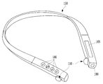
FIG. 2 shows an embodiment of a wireless acoustic apparatus according to the present invention.
3 is a rear perspective view of a wireless acoustic apparatus according to the present invention.
4 is a cross-sectional view taken along line AA 'of FIG. 3 for a wireless audio apparatus related to the present invention.
FIG. 5 shows an embodiment of a wireless acoustic apparatus according to the present invention.
6 shows an embodiment of a unit member related to the present invention.
FIG. 7 shows an embodiment of a wireless acoustic apparatus according to the present invention.
FIG. 1 illustrates an embodiment of a wireless
The
FIG. 2 shows an embodiment of a wireless acoustic apparatus 100 according to the present invention.
In order to complement the disadvantages of the prior art described above, the present invention is capable of carrying out various functions such as storing and charging the
The wireless acoustic apparatus 100 of the present invention may be physically divided into two components, that is, a
The
The
The wireless communication module may be provided on the PCB 113 inside the
The
Even if the
3 is a rear perspective view of a wireless acoustic apparatus 100 according to the present invention.
The coupling of the
The
The first
FIG. 4 is a cross-sectional view taken along the line A-A 'of FIG. 3 with respect to the wireless acoustic apparatus 100 according to the present invention.
The
The rear
Referring again to FIG. 2,
The
FIG. 5 illustrates an embodiment of a wireless acoustic apparatus 100 according to the present invention.
The
The control signal through the
In the case of the embodiment (a), the controller provided in the
In the case of the embodiment (b), if the
Figure 6 illustrates an embodiment of a
A
FIG. 7 illustrates an embodiment of a wireless acoustic apparatus 100 according to the present invention.
The
The scope of the present invention should be determined by rational interpretation of the appended claims, and all changes within the scope of equivalents of the present invention are included in the scope of the present invention.
100: wireless audio device 110: unit member
110a:
111: Receiver 112: Earpiece
113: Fee 114: Main battery
115: power supply terminal 116: second magnetic material
117: Data terminal 118: Touch input section
119: notification unit 120: proximity sensor reception unit
150: neck band housing 151: housing upper surface
152: auxiliary battery 160: detachable part
161: depressed surface 162: first pogo pin
163: first magnetic material 164: second pogo pin
165: touch input pad 167: proximity sensor transmitter
172: after the big government 1723: spring
173: elastic support 180: auxiliary speaker
Claims (12)
A main battery for supplying power to the wireless communication module;
A receiver for outputting sound according to the acoustic signal;
A unit member forming a columnar appearance and mounting the wireless communication module, the receiver and the main battery;
A neckband having a curved housing and a detachable portion to which the unit member is coupled at both lower ends of the housing; And
And an auxiliary battery mounted on the neckband for supplying power to the main battery when the receiver is coupled to the neckband.
Wherein the unit member comprises:
And a power terminal provided on a side of the column to supply power to the main battery,
Said neckband comprising:
A recessed surface provided in the detachable portion and including a shape corresponding to a part of the columnar shape; And
And a first pogo pin provided at the depressed surface position corresponding to the power source terminal when the unit member is coupled to the detachable unit and supplying power of the auxiliary battery to the main battery. device.
Wherein the column is a cylinder,
Wherein the depth of the detachable portion is deeper than the radius of the circular cylinder,
And a fastening portion provided at one end in the lower end of the detachable portion and projected when the unit member is engaged with the detachable portion and engaged with the detachable portion to fix the unit member Characterized by a wireless acoustic device.
Said neckband comprising:
And an elastic support member which is provided at the other end in the lower end direction of the detachable portion and is compressed when the unit member is engaged with the detachable portion and is protruded to fix the unit member when the unit member is coupled to the detachable portion, Further comprising: a second wireless communication device for communicating with the wireless communication device.
Said neckband comprising:
Further comprising a first magnetic material provided on the detachable portion,
Wherein the unit member comprises:
And a second magnetic material disposed at a position corresponding to the first magnetic material when the unit member is coupled to the neck band and generating attraction with the first magnetic material.
Wherein the unit member comprises:
A left unit member and a right unit member,
Wherein when the left unit member and the right unit member are engaged with the neck band, the ear piece of the left unit member and the ear piece of the right unit member face each other.
Wherein the unit member comprises:
And a data terminal for transmitting the received acoustic signal to the outside,
Said neckband comprising:
A second pogo pin for receiving the received acoustic signal in contact with the data terminal when the unit member is coupled to the detachable portion; And
Further comprising an auxiliary speaker provided at both ends of the housing for converting the sound signal received by the second pogo pin into sound.
Said neckband comprising:
A touch input pad for receiving a control signal; And
Further comprising a controller for transmitting the received control signal to the wireless communication module through the second pogo pin.
Said neckband comprising:
A touch input pad for receiving a control signal;
A wireless transceiver for transmitting and receiving the control signal; And
Further comprising a control unit for transmitting the received control signal to the terminal or the unit member through the wireless transceiver unit.
Wherein the unit member comprises:
A touch input unit provided on a bottom surface of the column to receive a control signal; And
And a control unit for transmitting the received control signal to the terminal through the wireless communication module.
Wherein the unit member comprises:
A left unit member and a right unit member,
And the control signals of the left unit member and the right unit member are distinguished.
Wherein the unit member comprises:
Further comprising a proximity sensor receiver,
Said neckband comprising:
A proximity sensor transmitter for sensing the proximity sensor when the proximity sensor is moved away from the housing by a predetermined distance to generate a proximity signal; And
And a notification unit for receiving and displaying the generated proximity signal.
Priority Applications (1)
| Application Number | Priority Date | Filing Date | Title |
|---|---|---|---|
| KR1020150026593A KR20160103779A (en) | 2015-02-25 | 2015-02-25 | Wireless sound equipment |
Applications Claiming Priority (1)
| Application Number | Priority Date | Filing Date | Title |
|---|---|---|---|
| KR1020150026593A KR20160103779A (en) | 2015-02-25 | 2015-02-25 | Wireless sound equipment |
Publications (1)
| Publication Number | Publication Date |
|---|---|
| KR20160103779A true KR20160103779A (en) | 2016-09-02 |
Family
ID=56942996
Family Applications (1)
| Application Number | Title | Priority Date | Filing Date |
|---|---|---|---|
| KR1020150026593A KR20160103779A (en) | 2015-02-25 | 2015-02-25 | Wireless sound equipment |
Country Status (1)
| Country | Link |
|---|---|
| KR (1) | KR20160103779A (en) |
Cited By (12)
| Publication number | Priority date | Publication date | Assignee | Title |
|---|---|---|---|---|
| KR20180136629A (en) * | 2017-06-15 | 2018-12-26 | 티케이디에스(주) | Neck band type wireless earphone |
| KR20190025495A (en) * | 2017-09-01 | 2019-03-11 | 크레신 주식회사 | Wireless earphone and charging case |
| KR101984562B1 (en) * | 2018-05-16 | 2019-05-31 | (주)파트론 | Portable audio equipment |
| KR200489806Y1 (en) * | 2018-08-23 | 2019-08-12 | 정웅모 | Output device of audio signal with bluetooth earphone and speaker |
| KR102071268B1 (en) * | 2019-07-03 | 2020-01-30 | 주식회사 블루콤 | Structure for communications between the wireless ear bud and the charge cradle |
| KR102121185B1 (en) * | 2019-06-12 | 2020-06-12 | 크레신 주식회사 | Wireless earphone and charging case set |
| US10735845B2 (en) | 2017-09-01 | 2020-08-04 | Cresyn Co., Ltd. | Wireless earphone and charging case |
| US10805706B2 (en) | 2017-10-23 | 2020-10-13 | Samsung Electronics Co., Ltd. | Battery changeable-type earbuds and apparatus for the same |
| WO2022030797A1 (en) * | 2020-08-04 | 2022-02-10 | 삼성전자 주식회사 | System comprising power supply case and wearable device, and method for controlling power supply of system |
| KR102417290B1 (en) * | 2021-11-26 | 2022-07-06 | 조형준 | Wireless earphone having functing of preventing loss |
| WO2024054458A1 (en) * | 2022-09-06 | 2024-03-14 | Apple Inc. | Devices, methods, and user interfaces for controlling operation of wireless electronic accessories |
| US11941319B2 (en) | 2020-07-20 | 2024-03-26 | Apple Inc. | Systems, methods, and graphical user interfaces for selecting audio output modes of wearable audio output devices |
-
2015
- 2015-02-25 KR KR1020150026593A patent/KR20160103779A/en unknown
Cited By (12)
| Publication number | Priority date | Publication date | Assignee | Title |
|---|---|---|---|---|
| KR20180136629A (en) * | 2017-06-15 | 2018-12-26 | 티케이디에스(주) | Neck band type wireless earphone |
| KR20190025495A (en) * | 2017-09-01 | 2019-03-11 | 크레신 주식회사 | Wireless earphone and charging case |
| US10735845B2 (en) | 2017-09-01 | 2020-08-04 | Cresyn Co., Ltd. | Wireless earphone and charging case |
| US10805706B2 (en) | 2017-10-23 | 2020-10-13 | Samsung Electronics Co., Ltd. | Battery changeable-type earbuds and apparatus for the same |
| KR101984562B1 (en) * | 2018-05-16 | 2019-05-31 | (주)파트론 | Portable audio equipment |
| KR200489806Y1 (en) * | 2018-08-23 | 2019-08-12 | 정웅모 | Output device of audio signal with bluetooth earphone and speaker |
| KR102121185B1 (en) * | 2019-06-12 | 2020-06-12 | 크레신 주식회사 | Wireless earphone and charging case set |
| KR102071268B1 (en) * | 2019-07-03 | 2020-01-30 | 주식회사 블루콤 | Structure for communications between the wireless ear bud and the charge cradle |
| US11941319B2 (en) | 2020-07-20 | 2024-03-26 | Apple Inc. | Systems, methods, and graphical user interfaces for selecting audio output modes of wearable audio output devices |
| WO2022030797A1 (en) * | 2020-08-04 | 2022-02-10 | 삼성전자 주식회사 | System comprising power supply case and wearable device, and method for controlling power supply of system |
| KR102417290B1 (en) * | 2021-11-26 | 2022-07-06 | 조형준 | Wireless earphone having functing of preventing loss |
| WO2024054458A1 (en) * | 2022-09-06 | 2024-03-14 | Apple Inc. | Devices, methods, and user interfaces for controlling operation of wireless electronic accessories |
Similar Documents
| Publication | Publication Date | Title |
|---|---|---|
| KR20160103779A (en) | Wireless sound equipment | |
| KR101848669B1 (en) | Wireless sound equipment | |
| KR101693268B1 (en) | Earset | |
| US8660055B2 (en) | Pseudo hub-and-spoke wireless audio network | |
| US20170272561A1 (en) | Wireless headset and method of controlling the same | |
| US20140233754A1 (en) | Headphone system with retractable microphone | |
| KR101745866B1 (en) | Bluetooth headset with walkie-talkie | |
| US9866966B2 (en) | Wireless audio system | |
| US10412480B2 (en) | Wearable personal acoustic device having outloud and private operational modes | |
| US8903309B2 (en) | True stereo wireless headset and method | |
| US20190327551A1 (en) | Wireless headphone system | |
| KR102048904B1 (en) | Wearable wireless speaker and wireless speaker system having the same | |
| US20180007460A1 (en) | Hifi system based on digital connection | |
| JP2007006420A (en) | Data communication system | |
| KR101366001B1 (en) | Vibrating headphones | |
| KR101759970B1 (en) | Bone conduction vibrator and the ring type communication device using the same | |
| KR20170011549A (en) | Wireless earset | |
| KR20160128086A (en) | A wireless headset | |
| US20170374447A1 (en) | Earbuds for use both wirelessly and with a wired connection | |
| KR20190079867A (en) | Audio device using detachable bluetooth speaker and control method thereof | |
| KR101469559B1 (en) | Backpack | |
| CN111988696A (en) | Earphone set | |
| CN211630350U (en) | Multifunctional Bluetooth earphone | |
| KR101561782B1 (en) | Separated type docking speaker | |
| JPS5845233B2 (en) | wireless earphone device |