KR20160102280A - Method of manufacturing tube, and tube - Google Patents
Method of manufacturing tube, and tube Download PDFInfo
- Publication number
- KR20160102280A KR20160102280A KR1020167020046A KR20167020046A KR20160102280A KR 20160102280 A KR20160102280 A KR 20160102280A KR 1020167020046 A KR1020167020046 A KR 1020167020046A KR 20167020046 A KR20167020046 A KR 20167020046A KR 20160102280 A KR20160102280 A KR 20160102280A
- Authority
- KR
- South Korea
- Prior art keywords
- main body
- tube main
- hole
- pipe
- holes
- Prior art date
Links
Images


Classifications
-
- B—PERFORMING OPERATIONS; TRANSPORTING
- B23—MACHINE TOOLS; METAL-WORKING NOT OTHERWISE PROVIDED FOR
- B23K—SOLDERING OR UNSOLDERING; WELDING; CLADDING OR PLATING BY SOLDERING OR WELDING; CUTTING BY APPLYING HEAT LOCALLY, e.g. FLAME CUTTING; WORKING BY LASER BEAM
- B23K26/00—Working by laser beam, e.g. welding, cutting or boring
- B23K26/20—Bonding
- B23K26/21—Bonding by welding
- B23K26/24—Seam welding
- B23K26/28—Seam welding of curved planar seams
- B23K26/282—Seam welding of curved planar seams of tube sections
-
- B—PERFORMING OPERATIONS; TRANSPORTING
- B23—MACHINE TOOLS; METAL-WORKING NOT OTHERWISE PROVIDED FOR
- B23K—SOLDERING OR UNSOLDERING; WELDING; CLADDING OR PLATING BY SOLDERING OR WELDING; CUTTING BY APPLYING HEAT LOCALLY, e.g. FLAME CUTTING; WORKING BY LASER BEAM
- B23K26/00—Working by laser beam, e.g. welding, cutting or boring
- B23K26/08—Devices involving relative movement between laser beam and workpiece
- B23K26/0823—Devices involving rotation of the workpiece
-
- B—PERFORMING OPERATIONS; TRANSPORTING
- B23—MACHINE TOOLS; METAL-WORKING NOT OTHERWISE PROVIDED FOR
- B23K—SOLDERING OR UNSOLDERING; WELDING; CLADDING OR PLATING BY SOLDERING OR WELDING; CUTTING BY APPLYING HEAT LOCALLY, e.g. FLAME CUTTING; WORKING BY LASER BEAM
- B23K26/00—Working by laser beam, e.g. welding, cutting or boring
- B23K26/14—Working by laser beam, e.g. welding, cutting or boring using a fluid stream, e.g. a jet of gas, in conjunction with the laser beam; Nozzles therefor
-
- B—PERFORMING OPERATIONS; TRANSPORTING
- B23—MACHINE TOOLS; METAL-WORKING NOT OTHERWISE PROVIDED FOR
- B23K—SOLDERING OR UNSOLDERING; WELDING; CLADDING OR PLATING BY SOLDERING OR WELDING; CUTTING BY APPLYING HEAT LOCALLY, e.g. FLAME CUTTING; WORKING BY LASER BEAM
- B23K26/00—Working by laser beam, e.g. welding, cutting or boring
- B23K26/70—Auxiliary operations or equipment
- B23K26/702—Auxiliary equipment
-
- F—MECHANICAL ENGINEERING; LIGHTING; HEATING; WEAPONS; BLASTING
- F16—ENGINEERING ELEMENTS AND UNITS; GENERAL MEASURES FOR PRODUCING AND MAINTAINING EFFECTIVE FUNCTIONING OF MACHINES OR INSTALLATIONS; THERMAL INSULATION IN GENERAL
- F16L—PIPES; JOINTS OR FITTINGS FOR PIPES; SUPPORTS FOR PIPES, CABLES OR PROTECTIVE TUBING; MEANS FOR THERMAL INSULATION IN GENERAL
- F16L13/00—Non-disconnectible pipe-joints, e.g. soldered, adhesive or caulked joints
- F16L13/02—Welded joints
- F16L13/0245—Welded joints with holes in the sleeve or spigot being filled with weld
-
- B—PERFORMING OPERATIONS; TRANSPORTING
- B23—MACHINE TOOLS; METAL-WORKING NOT OTHERWISE PROVIDED FOR
- B23K—SOLDERING OR UNSOLDERING; WELDING; CLADDING OR PLATING BY SOLDERING OR WELDING; CUTTING BY APPLYING HEAT LOCALLY, e.g. FLAME CUTTING; WORKING BY LASER BEAM
- B23K2101/00—Articles made by soldering, welding or cutting
- B23K2101/04—Tubular or hollow articles
- B23K2101/06—Tubes
-
- B23K2201/06—
Abstract
관 제조방법 및 관에 있어서, 접속핀(300)의 제1 삽입부(301)를 제1 관본체(100)의 제1 구멍(101)의 단부에 삽입하고 제2 삽입부(302)를 제2 관본체(200)의 제1 구멍(201)의 단부에 삽입함으로써 제1 관본체(100)와 제2 관본체(200)를 위치결정 연결하는 공정과, 제1 관본체(100)와 제2 관본체(200)의 연결부의 외주부 및 접속핀(300)이 삽입된 제1 구멍(101, 201)의 내주부를 둘레 전체에 걸쳐 용접하는 공정과, 제1 관본체(100)의 제1 구멍(101)과 제2 관본체(200)의 제1 구멍(201) 내부에 잔존하는 접속핀(300)을 제거하는 공정을 가짐으로써 내부에 설치된 여러 개의 구멍들 사이의 높은 실 성능을 확보한다.The first insertion portion 301 of the connection pin 300 is inserted into the end of the first hole 101 of the first tube main body 100 and the second insertion portion 302 is inserted into the end of the first hole 101 of the first tube main body 100, A step of positioning and connecting the first tube main body 100 and the second tube main body 200 by inserting the second tube main body 200 into an end portion of the first hole 201 of the second tube main body 200, A step of welding an outer peripheral portion of a connecting portion of the two-tube main body 200 and an inner peripheral portion of the first holes 101 and 201 in which the connecting pin 300 is inserted over the entire circumference; The step of removing the connecting pin 300 remaining in the hole 101 and the first hole 201 of the second tube main body 200 is provided to secure a high thread performance between the plurality of holes provided therein .
Description
본 발명은 내부에 길이 방향에 따르는 여러 개의 구멍이 형성된 관을 제조하는 관 제조방법 및 이 관의 제조방법에 의해 제조된 관에 관한 것이다.The present invention relates to a pipe manufacturing method for manufacturing a pipe having a plurality of holes along its length in the inside thereof, and a pipe manufactured by the manufacturing method of the pipe.
내부에 길이 방향에 따르는 구멍이 형성된 관을 제조하는 방법으로서는 예를 들면 드릴 등 공구에 의해 봉상 부재의 내부에 구멍을 절삭 가공하는 방법이 고려된다. 그러나 봉상 부재의 길이가 길고 형성하는 구멍이 소경이면 가늘고 긴 드릴을 사용하게 되고 드릴 회전시에 선단부가 흔들거려 높은 정밀도의 구멍을 가공하는 것이 곤란하게 된다. 때문에 소정의 길이보다 짧은 봉상 부재의 내부에 구멍을 절삭 가공하고 구멍이 형성된 봉상 부재를 직렬로 접합하는 것에 의해 내부에 구멍이 형성된 소정 길이의 관을 제조할 수 있다.As a method of manufacturing a pipe having a hole in the longitudinal direction inside thereof, a method of cutting a hole in the inside of the rod-like member by a tool such as a drill is considered. However, if the length of the rod-like member is long and the hole to be formed is a small diameter, a slender and long drill is used, and when the drill is rotated, the tip portion is shaken, making it difficult to process the hole with high precision. Therefore, it is possible to manufacture a tube having a predetermined length, in which holes are formed by cutting a hole in the inside of the rod-like member shorter than the predetermined length and joining the rod-shaped members formed with the holes in series.
이러한 관의 제조방법으로서는 예를 들면 하기 특허문헌에 기재된 것이 있다. 특허문헌 1에 기재된 유압성형관의 제조방법은 여러 개의 원통상 금속 파이프를 동축으로 맞대게 하는 한편 그 맞대임부의 내부에 경질 재료로 이루어지는 후육 원통상 배킹지그(backing jig)를 배치하고 이 배킹지그에 의해 맞대임부를 지지한 상태에서 회전 공구를 핀과 일체적으로 고속회전시키고 맞대임부에 삽입하고 주방향으로 상대 이동시킴으로써 마찰 교반 접합한다. 또한, 특허문헌 2에 기재된 것은 하측의 칼럼 상단부에 칼럼 배킹금속의 제1 감합부를 감합 삽입하여 고정시키고 칼럼 배킹금속의 제2 감합부에 상측의 칼럼 하단부를 외감(外嵌)하여 고정시키고 칼럼 배킹금속을 개재하여 상하 칼럼을 맞대이게 한 다음 각 칼럼의 단부사이를 용접하여 접속시키는 것이다.Examples of the method for producing such a tube include those described in the following patent documents. In the method of manufacturing a hydraulic forming tube described in Patent Document 1, a plurality of cylindrical metal pipes are coaxially aligned with each other while a backing circular backing jig made of a hard material is disposed inside the butt joint, The rotary tool is integrally rotated at a high speed integrally with the pin, inserted into the butt portion, and moved in the main direction to perform friction stir welding. In addition, in Patent Document 2, a first fitting portion of a columnar backing metal is inserted and fixed to an upper end portion of a lower column, a lower end portion of the upper column is fitted to a second fitting portion of the columnar backing metal to fix the column backing, The upper and lower columns are brought into contact with each other through the metal, and the end portions of the respective columns are welded and connected.
상술한 종래의 관 제조방법에서는 내부에 여러 개의 구멍을 가지고 높은 실 성능이 확보된 관을 제조하는 것은 곤란하다. 즉 종래는 2개의 관을 지그 등에 의해 단부를 서로 맞대이게 하고 이 맞대임부를 외부로부터 용접하여 접합시키고 있다. 한편 내부에 여러 개의 구멍을 가지는 2개의 관을 접합하는 경우에 각 구멍에 지그 등을 삽입하여 단부를 서로 맞대이게 하고 이 맞대임부를 외부로부터 용접하여 접합하게 된다. 그러면 접합된 관은 맞대임부에서 외주부가 접합되어 있지만 각 구멍의 주위는 단면사이가 당접해 있을 뿐이기때문에 충분한 실 성능이 확보되어 있지 않는다. 그 때문에 이 관의 각 구멍에 다른 종류의 유체를 유통시켰을 경우에 관의 접합부에서 유체의 누설이 발생하고 다른 종류의 유체들사이가 서로 섞여버릴 우려가 있다.In the conventional tube manufacturing method described above, it is difficult to manufacture a tube having a plurality of holes therein and ensuring a high seal performance. In other words, conventionally, the two tubes are made to come into contact with each other by jigs or the like, and the butt joints are welded from the outside to join them. On the other hand, in the case of joining two pipes having a plurality of holes therein, a jig or the like is inserted into each of the holes so that the ends are brought into contact with each other, and the butt joint is welded from outside. Then, although the outer periphery of the joined pipe is joined to the outer periphery of the butt joint, sufficient perforation performance is not ensured because the periphery of each hole is only in contact with the cross section. Therefore, when a different kind of fluid is circulated through each of the holes of the tube, fluid leakage may occur at the joint portion of the tube, and other types of fluids may be mixed with each other.
본 발명은 상술한 과제를 해결하기 위한 것으로서 내부에 마련된 여러 개의 구멍들 사이에 높은 실 성능을 확보할 수 있는 소정 길이의 관을 제조하는 관 제조방법 및 관을 제공하는 것을 목적으로 한다.SUMMARY OF THE INVENTION It is an object of the present invention to provide a tube manufacturing method and a tube for manufacturing a tube having a predetermined length capable of ensuring a high seal performance between a plurality of holes provided therein.
상기 목적을 달성하기 위한 본 발명의 관 제조방법은 여러 개의 구멍을 가지는 제1 관본체와 여러 개의 구멍을 가지는 제2 관본체를 직렬로 접속하는 관 제조방법으로서 접속핀의 일단부를 상기 제1 관본체의 구멍 단부에 삽입하고 상기 접속핀의 타단부를 상기 제2 관본체의 구멍 단부에 삽입함으로써 상기 제1 관본체와 상기 제2 관본체를 위치결정 연결하는 공정과, 상기 제1 관본체와 상기 제2 관본체의 연결부의 외주부 및 상기 접속핀이 삽입된 상기 구멍의 내주부를 둘레 전체에 걸쳐 용접하는 공정과, 상기 제1 관본체의 구멍과 상기 제2 관본체의 구멍 내부에 잔존하는 상기 접속핀을 제거하는 공정을 구비하는 것을 특징으로 한다.According to an aspect of the present invention, there is provided a method of manufacturing a tube for connecting a first tube main body having a plurality of holes and a second tube main body having a plurality of holes in series, Positioning the first tube main body and the second tube main body by inserting the other end of the connecting pin into the hole end of the main body and inserting the other end of the connecting pin into the hole end of the second tube main body; A step of welding an outer peripheral portion of the connecting portion of the second pipe body and an inner peripheral portion of the hole into which the connecting pin is inserted through the entire circumference; And a step of removing the connecting pin.
따라서 각 관본체의 연결부의 외주부 및 접속핀이 삽입된 구멍의 내주부를 둘레 전체에 걸쳐 용접함으로써 각 구멍 사이가 용융부로 되어서 높은 실 성능을 확보할 수 있고 또한 각 관본체 구멍 내부에 잔존하는 접속핀을 제거함으로써 소정 길이의 관을 용이하게 제조할 수 있다.Therefore, the outer peripheral portion of the connecting portion of each tube main body and the inner peripheral portion of the hole into which the connecting pin is inserted are welded over the entire circumference, so that the space between the respective holes becomes a molten portion. Thus, high thread performance can be ensured, By removing the pin, a pipe of a predetermined length can be easily manufactured.
본 발명의 관 제조방법에서는 상기 제1 관본체의 구멍과 상기 제2 관본체의 구멍 내부에 잔존하는 상기 접속핀을 상기 제1 관본체의 구멍 및 상기 제2 관본체의 구멍과 동일한 직경 치수로 절삭 가공하는 것을 특징으로 하고 있다.In the pipe manufacturing method of the present invention, the connecting pin remaining in the hole of the first pipe main body and the hole of the second pipe main body is formed in the same diameter as the hole of the first pipe main body and the hole of the second pipe main body And a cutting process is performed.
따라서 각 관본체의 구멍을 가이드로서 이용함으로써 이 구멍 내부에 잔존하는 접속핀을 용이하게 제거할 수 있고 접속핀을 이 구멍과 동일한 직경 치수로 절삭 가공함으로써 소정 길이의 정밀도가 높은 구멍을 형성할 수 있다.Therefore, by using the hole of each pipe body as a guide, the connecting pin remaining in the hole can be easily removed, and the connecting pin can be cut to the same diameter as the hole, have.
본 발명의 관 제조방법에서는 상기 제1 관본체 및 상기 제2 관본체는 상기 각 구멍의 단부에 상기 구멍의 내경보다 큰 감합구멍이 형성되는 한편 상기 접속핀은 상기 제1 관본체 및 상기 제2 관본체의 상기 각 구멍에 삽입되는 한쌍의 삽입부와, 상기 한쌍의 삽입부 사이에서 상기 제1 관본체 및 상기 제2 관본체의 각 감합구멍에 감합되는 감합부가 설치되는 것을 특징으로 하고 있다.In the pipe manufacturing method of the present invention, the first tube main body and the second tube main body are formed with fitting holes having an outer diameter larger than the inner diameter of the hole at the end of each hole, A pair of insertion portions to be inserted into the respective holes of the tube main body and a fitting portion to be fitted to each of the fitting holes of the first tube main body and the second tube main body between the pair of insertion portions are provided.
따라서 접속핀의 삽입부가 각 관본체의 구멍에 각각 삽입되고 감합부가 각 관본체의 각 감합구멍에 감합되기때문에 접속핀을 각 관본체내에 적정한 량만 삽입하는 것이 가능해지고 내부에 접속핀이 배치되어 있는 각 관본체를 외주부로부터 적정하게 용접할 수 있다.Accordingly, since the insertion portions of the connection pins are respectively inserted into the holes of the respective tube bodies, and the fitting portions are fitted into the respective fitting holes of the respective tube bodies, only a proper amount of the connecting pins can be inserted into the respective tube bodies and the connecting pins are arranged inside Each tube main body can be appropriately welded from the outer peripheral portion.
본 발명의 관 제조방법에서는 상기 제1 관본체와 상기 제2 관본체의 연결부에 따른 용접 폭은 상기 접속핀에 따른 상기 감합부의 길이보다도 크게 설정되는 것을 특징으로 하고 있다.In the pipe manufacturing method of the present invention, the welding width along the connecting portion between the first pipe body and the second pipe body is set larger than the length of the fitting portion along the connecting pin.
따라서 접속핀은 감합부가 전부 용융부로 되는 것에 의해 실 성능을 확보할 수 있다.Therefore, the connecting pin is made into a molten portion as a whole, so that the actual performance can be secured.
본 발명의 관 제조방법에서는 상기 접속핀은 솔리드(solid)로 형성되는 것을 특징으로 하고 있다.In the pipe manufacturing method of the present invention, the connecting pin is formed as a solid.
따라서 접속핀을 솔리드로 하는 것에 의해 용접시에 따른 각 구멍의 용융 변형을 방지할 수 있다.Therefore, by making the connecting pin solid, it is possible to prevent the deformation of each hole due to welding.
본 발명의 관 제조방법에서는 상기 제1 관본체 및 상기 제2 관본체는 외주부측에 주방향으로 소정 간격으로 여러 개의 외주 구멍이 형성되고 상기 제1 관본체와 상기 제2 관본체의 연결부의 외주부 및 상기 접속핀이 삽입된 상기 외주 구멍의 내주부를 둘레 전체에 걸쳐 용접한 후 상기 제1 관본체 및 상기 제2 관본체의 중심부를 피용융부까지 절삭 가공함으로써 중심 구멍을 형성하는 것을 특징으로 하고 있다.In the pipe manufacturing method of the present invention, the first tube main body and the second tube main body have a plurality of outer peripheral holes formed at a predetermined interval in the main direction on the outer peripheral side, and the outer peripheral portion of the connecting portion of the first tube main body and the second tube main body And a center hole is formed by cutting the central portion of the first tube main body and the second tube main body to the fused portion after welding the inner peripheral portion of the outer peripheral hole into which the connecting pin is inserted over the entire circumference, .
따라서 제1 관본체 및 제2 관본체의 중심부를 피용융부까지 절삭 가공하여 중심 구멍을 형성하는 것에 의해 제1 관본체와 제2 관본체의 접속부는 전부 용융부로 되고 실 성능을 확보할 수 있다.Therefore, by forming the center hole by machining the central portion of the first tube main body and the second tube main body to the fused portion, the connecting portion between the first tube main body and the second tube main body becomes a completely melted portion and the actual performance can be ensured .
또한 본 발명의 관은 여러 개의 구멍을 가지는 제1 관본체와 여러 개의 구멍을 가지는 제2 관본체가 직렬로 접속되는 동시에 상기 제1 관본체와 상기 제2 관본체의 접속부에 전 영역에 걸쳐 용융부가 설치되는 것을 특징으로 한다.Further, the tube of the present invention is characterized in that a first tube main body having a plurality of holes and a second tube main body having a plurality of holes are connected in series, and at the connection portion between the first tube main body and the second tube main body, Is installed.
따라서 소정의 길이를 확보할 수 있는 동시에 내부에 설치된 여러 개의 구멍들 사이에 높은 실 성능을 확보할 수 있다.Therefore, a predetermined length can be ensured and a high thread performance can be ensured between a plurality of holes provided inside.
본 발명의 관 제조방법 및 관에 의하면 접속핀의 일단부를 제1 관본체의 구멍 단부에 삽입하고 타단부를 제2 관본체의 구멍 단부에 삽입하고 각 관본체의 연결부의 외주부 및 접속핀이 삽입된 구멍의 내주부를 둘레 전체에 걸쳐 용접하고 구멍의 내부에 잔존하는 접속핀을 제거함으로써 관을 제조하기 때문에 내부에 설치된 여러 개의 구멍들사이에 높은 실 성능을 확보할 수 있는 소정 길이의 관을 제공할 수 있다.According to the pipe manufacturing method and the pipe of the present invention, one end of the connecting pin is inserted into the hole end of the first pipe body and the other end is inserted into the hole end of the second pipe body, Since the tube is manufactured by welding the inner peripheral portion of the hole through the entire circumference and removing the connecting pin remaining inside the hole, it is possible to manufacture a tube having a predetermined length .
도 1은 본 실시형태의 관 제조장치를 나타내는 개략구성도이다.
도 2는 본 실시형태의 관의 일부를 잘라 낸 정면도이다.
도 3은 관의 단면도이다.
도 4는 본 실시형태의 관 제조방법을 나타내는 개략도이다.
도 5는 본 실시형태의 관 제조방법을 나타내는 개략도이다.
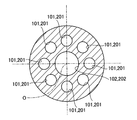
도 6은 도 5의 VI-VI단면도이다.
도 7은 본 실시형태의 관 제조방법을 나타내는 개략도이다.
도 8은 도 7의 VIII-VIII단면도이다.
도 9는 본 실시형태의 관 제조방법을 나타내는 개략도이다.
도 10은 본 실시형태의 관 제조방법을 나타내는 개략도이다.
도 11은 도 10의 XI-XI단면도이다.1 is a schematic configuration diagram showing a pipe manufacturing apparatus of the present embodiment.
Fig. 2 is a front view showing a part of the pipe of the embodiment. Fig.
3 is a cross-sectional view of the tube.
4 is a schematic view showing a pipe manufacturing method of the present embodiment.
5 is a schematic view showing a pipe manufacturing method according to the present embodiment.
6 is a cross-sectional view taken along the line VI-VI in Fig.
7 is a schematic view showing a tube manufacturing method according to the present embodiment.
8 is a sectional view taken along the line VIII-VIII in Fig.
9 is a schematic view showing a pipe manufacturing method of the present embodiment.
10 is a schematic view showing a tube manufacturing method of the present embodiment.
11 is a cross-sectional view taken along the line XI-XI in Fig.
이하 첨부 도면을 참조하여 본 발명에 관한 관의 제조방법 및 관의 호적한 실시형태를 상세하게 설명한다. 또한, 이 실시 형태에 의해 본 발명이 한정되는 것이 아니며, 또한 실시 형태가 여러 개인 경우에는 각 실시 형태를 조합하여 구성하는 것도 포함하도록 한다.BEST MODE FOR CARRYING OUT THE INVENTION Hereinafter, a preferred embodiment of a pipe manufacturing method and pipe according to the present invention will be described in detail with reference to the accompanying drawings. It should be noted that the present invention is not limited to the embodiments, and in the case where there are several embodiments, the embodiments may be combined.
도 1은 본 실시형태의 관 제조장치를 나타내는 개략구성도이다.1 is a schematic configuration diagram showing a pipe manufacturing apparatus of the present embodiment.
본 실시형태의 관 제조장치에서 도 1에 나타내는 바와 같이 관(P)은 도시하지 않은 지지대에 지지되고 회전구동부(11)에 의해 화살표방향으로 회전가능하게 지지되어 있다. 관(P)의 윗쪽에 레이저 용접 헤드(12)가 배치되어 있고 레이저 용접 헤드(12)는 광학계(13)와 가스노즐(14)을 가지고 있다. 그리고 레이저 용접 헤드(12)는 광파이퍼(15)를 개재하여 레이저 발진기(16)가 연결되어 있다.1, the pipe P is supported by a support (not shown) and is rotatably supported by a
또한 관(P)의 윗쪽에 레이저 용접 헤드(12)와 나란히 냉각노즐(17)이 배치되어 있다. 실드가스공급부(18)는 제1 배관 (19)에 의해 레이저 용접 헤드(12)에 연결되는 동시에 도중에서 분기된 제2 배관(20)에 의해 냉각노즐(17)에 연결되어 있다. 이 경우 관(P)의 중심을 통하는 연직선(O)에 대하여 레이저 용접 헤드(12)와 냉각노즐(17)이 대상위치에 배치되어 있다.And a
센서(21)는 관(P)의 회전속도 및 회전위치를 검출하는 장치이고 제어장치(22)는 센서(21)가 검출한 관(P)의 회전속도 및 회전위치에 근거하여 회전구동부(11), 레이저 발진기(16), 실드가스공급부(18)를 제어한다.The
따라서 회전구동부(11)는 관(P)을 회전시키는 한편 레이저 용접 헤드(12)는 광파이퍼(15)를 개재하여 전송되는 레이저 빛을 광학계(13)로 집광하고 레이저빔으로서 관(P)의 맞대임부에 조사하는 동시에 용접부(용융부)의 산화를 방지하는 실드가스를 가스노즐(14)로부터 분사한다. 또한 냉각노즐(17)은 실드가스를 분사하여 용접부를 냉각시킨다.Therefore, the
본 실시형태의 관 제조방법은 이 관의 제조장치를 이용하여 내부에 길이 방향에 따르는 여러 개의 구멍이 형성된 관을 제조한다.The pipe manufacturing method of the present embodiment uses a manufacturing apparatus of this pipe to manufacture a pipe having a plurality of holes in the longitudinal direction thereof.
도 2는 본 실시형태의 관의 일부를 잘라 낸 정면도이고 도 3은 관의 단면도이다.Fig. 2 is a front view showing a part of the pipe of the embodiment, and Fig. 3 is a sectional view of the pipe.
관(P)은 도 2에 나타내는 바와 같이 여러 개(본 실시형태에서는 9개)의 구멍(101), (102)을 가지는 제1 관본체(100)와, 여러 개(본 실시형태에서는 9개)의 구멍(201), (202)을 가지는 제2 관본체(200)가 직렬로 접속되는 동시에 각 구멍(101), (102)과 각 구멍(201), (202)이 동심상으로 연통되고 제1 관본체(100)와 제2 관본체(200)의 접속부에 전영역에 걸쳐 용융부 (용접부)(W)가 설치되어 있다. 여기에서 용융부는 용접부로서 모재(母材)가 용융된 후에 고체화된 영역이다.As shown in FIG. 2, the pipe P includes a
여기에서 제1 구멍(외주 구멍)(101), (201)은, 각 관본체(100), (200)의 중심(O)으로부터 동등한 거리에 위치하는 동시에 서로 주방향으로 동등한 간격으로 위치하는 소경의 구멍이다. 또한 제2 구멍(중심 구멍)(102), (202)은 각 관본체(100), (200)의 중심(O)에 위치하는 제1 구멍(101), (201)보다 대경의 구멍이다.Here, the first holes (outer perforations) 101 and 201 are arranged at equal distances from the center O of the
여기에서 본 실시형태의 관 제조방법에 대하여 상세하게 설명한다.Hereinafter, the pipe manufacturing method of the present embodiment will be described in detail.
도 4는 본 실시형태의 관 제조방법을 나타내는 개략도이고, 도 5는 본 실시형태의 관 제조방법을 나타내는 개략도이고, 도 6은 도 5의 VI-VI단면도이고, 도 7은 본 실시형태의 관 제조방법을 나타내는 개략도이고, 도 8은 도 7의 VIII-VIII단면도이고, 도 9는 본 실시형태의 관 제조방법을 나타내는 개략도이고, 도 10은 본 실시형태의 관 제조방법을 나타내는 개략도이고, 도 11은 도 10의 XI-XI단면도이다.5 is a cross-sectional view taken along the line VI-VI in Fig. 5, and Fig. 7 is a cross-sectional view taken along line VI-VI in Fig. FIG. 8 is a cross-sectional view taken along the line VIII-VIII of FIG. 7, FIG. 9 is a schematic view showing a pipe manufacturing method of the present embodiment, FIG. 10 is a schematic view showing a pipe manufacturing method of the present embodiment, 11 is a cross-sectional view taken along the line XI-XI in Fig.
본 실시형태의 관 제조방법은 여러 개의 구멍(101)을 가지는 제1 관본체(100)와 여러 개의 구멍(201)을 가지는 제2 관본체(200)를 직렬로 접속하는 관 제조방법으로서 접속핀(300)의 일단부를 제1 관본체(100)의 구멍(101)의 단부에 삽입하고 접속핀(300)의 타단부를 제2 관본체(200)의 구멍(201)의 단부에 삽입함으로써 제1 관본체(100)와 제2 관본체(200)를 위치결정 연결하는 공정과, 제1 관본체(100)와 제2 관본체(200)의 연결부의 외주부 및 접속핀(300)이 삽입된 구멍(101), (201)의 내주부를 둘레 전체에 걸쳐 용접하는 공정과, 제1 관본체(100)의 구멍(101)과 제2 관본체(200)의 구멍(201)의 내부에 잔존하는 접속핀(300)을 제거하는 공정을 가진다.The pipe manufacturing method of the present embodiment is a pipe manufacturing method for connecting a
이하, 본 실시형태의 관 제조방법을 구체적으로 설명한다.Hereinafter, the tube manufacturing method of the present embodiment will be described in detail.
도 4에 나타내는 바와 같이 제1 관본체(100)는 여러 개의 제1 구멍(101)이 형성되는 동시에 접속하는 측의 단부에 제1 구멍(101)의 내경보다 큰 감합구멍(103)이 형성되어 있다. 이 감합구멍(103)은 원반형상을 이루고 제1 구멍(101)에 연통하는 동시에 제1 관본체(100)에 따른 접속하는 측의 단면(104)에 개구하고 있다. 한편 제2 관본체(200)는 여러 개의 제1 구멍(201)이 형성되는 동시에 접속하는 측의 단부에 제1 구멍(201)의 내경보다 큰 감합구멍(203)이 형성되어 있다. 이 감합구멍(203)은 원반형상을 이루고 제1 구멍(201)에 연통하는 동시에 제2 관본체(200)에 따른 접속하는 측의 단면(204)에 개구하고 있다. 제1 관본체(100)에 따른 제1 구멍(101)과 감합구멍(103)은 제2 관본체(200)에 따른 제1 구멍(201)과 감합구멍(203)과 같은 치수로 되어 있다.As shown in Fig. 4, the
또한 제1 관본체(100)는 각 제1 구멍(101)보다 중심측의 단면(104)에 원주형상을 이루는 철부(凸部)(105)가 형성되어 있다. 한편, 제2 관본체(200)는 각 제1 구멍(201)보다 중심측의 단면(204)에 원주형상을 이루는 요부(凹部)(205)가 형성되어 있다.In the
접속핀(300)은 솔리드로 형성되고 제1 관본체(100)의 제1 구멍(101)에 삽입 가능한 제1 삽입부(301)과, 제2 관본체(200)의 제1 구멍(201)에 삽입가능한 제2 삽입부(302)를 가지고 있다. 또한 접속핀(300)은 한쌍의 삽입부(301), (302)의 사이에서 각 관본체(100), (200)의 감합구멍(103), (203)에 각각 감합하는 감합부(303)를 가지고 있다. 이 감합부(303)는 폭이 각 감합구멍(103), (203)의 깊이를 합친 치수로 되어 있다.The
먼저 도 5 및 도 6에 나타내는 바와 같이 접속핀(300)의 제1 삽입부(301)를 제1 관본체(100)의 제1 구멍(101)의 단부에 삽입하는 동시에 감합부(303)의 일부를 제1 관본체(100)의 감합구멍(103)에 삽입한다. 다음에 접속핀(300)의 제2 삽입부(302)를 제2 관본체(200)의 제1 구멍(201)의 단부에 삽입하는 동시에 감합부(303)의 일부를 제2 관본체(200)의 감합구멍(203)에 삽입한다. 이 경우 제1 관본체(100) 및 제2 관본체(200)에 따른 모든 제1 구멍(101), (201)에 대하여 접속핀(300)을 삽입한다. 또한 이 때 제1 관본체(100)의 철부(105)와 제2 관본체(200)의 요부(205)가 감합된다. 그 때문에 제1 관본체(100)와 제2 관본체(200)는 단면(104), (204)사이에 틈새 없이 밀착하고 제1 구멍(101), (201)사이가 동심상으로 연통하도록 주방향 및 직경 방향의 위치결정이 행해져서 연결된다.5 and 6, the
계속하여 도 1에 나타내는 바와 같이 관의 제조장치를 이용하여 제1 관본체(100)와 제2 관본체(200)를 용접하여 접속한다. 즉 회전구동부(11)에 의해 관(P)을 회전시키고 이 상태에서 레이저 용접 헤드(12)가 레이저빔을 관(P)의 연결부에 조사하는 것에 의해 관(P) 둘레 전체를 용접한다. 이 때 도 7 및 도 8에 나타내는 바와 같이 레이저 용접 헤드(12)는 제1 관본체(100)의 단면(104)과 제2 관본체(200)의 단면(204)이 틈새 없이 밀착한 연결부에 대하여 레이저빔(B)을 조사한다. 이 때 레이저 용접 헤드(12)에 의한 레이저빔(B)의 조사 폭, 즉 제1 관본체(100)와 제2 관본체(200)의 연결부에 따른 용접 폭을 접속핀(300)에 따른 감합부(303)의 길이보다도 크게 설정한다.Subsequently, as shown in Fig. 1, the first tube
또한 레이저 용접 헤드(12)는 제1 관본체(100)와 제2 관본체(200)의 연결부의 외주부로부터 여러 개의 제1 구멍(101), (201)이 형성된 위치보다도 중심측까지 레이저빔(B)을 조사한다. 그 때문에 레이저 용접 헤드(12)에 의한 레이저빔(B)의 조사 깊이는 각 관본체(100), (200)의 외주면으로부터 여러 개의 제1 구멍(101), (201)이 형성된 위치 이상으로 되고 제1 관본체(100)와 제2 관본체(200)에 따른 접속핀(300)이 삽입된 제1 구멍(101), (201)의 내주부를 둘레 전체에 걸쳐 용접할 수 있다.The
즉 제1 관본체(100)와 제2 관본체(200)의 연결부는 접속핀(300)의 감합부(303)와 함께 용융하고 철부(105)의 외측 일대가 용접부(용융부)(W)로 된다.The connecting portion between the first tube
그리고 도 9에 나타내는 바와 같이 제1 관본체(100)의 제1 구멍(101)과 제2 관본체(200)의 제1 구멍(201)의 내부에 잔존하는 접속핀(300)을 제거한다. 이 때 각 제1 구멍(101), (201)을 가이드로서 도시하지 않은 절삭 공구를 삽입하고 또한 길이 방향으로 이동시킴으로써 각 제1 구멍(101), (201)의 내부에 잔존하는 접속핀(300)을 각 제1 구멍(101), (201)과 동일한 직경 치수로 절삭 가공한다. 즉, 절삭공구를 예를 들면 제1 구멍(101)으로부터 제1 구멍(201)에 삽입 통과 하는 것에 의해 내부의 접속핀(300)뿐만 아니라 접속핀(300)이 용융 고체화된 용접부(W)도 절삭 가공한다.9, the
그 후 제1 관본체(100)와 제2 관본체(200)가 접속되고 제1 구멍(101)과 제1 구멍(201)이 전부 연통하면 도 10 및 도 11에 나타내는 바와 같이 제1 구멍(101) 및 제1 구멍(201)의 내측에서 각 관본체(100), (200)의 중심부에 제2 구멍(102), (202)을 절삭 가공한다. 이 때 관본체(100), (200)의 중심(O)으로부터 용접부(W)까지 절삭 가공함으로써 제1 관본체(100)의 철부(105)와 제2 관본체(200)의 요부(205)가 제거되게 된다.When the
그 결과 도 2에 나타내는 바와 같이 여러 개의 제1 구멍(101), (102)을 가지는 제1 관본체(100)와, 여러 개의 구멍(201), (202)을 가지는 제2 관본체(200)가 직렬로 접속되는 동시에 각 구멍(101), (102)과 각 구멍(201), (202)이 동심상으로 연통되고 제1 관본체(100)와 제2 관본체(200)의 접속부에 전영역에 걸쳐 용접부(용융부)(W)가 설치된 관(P)이 제조된다.2, a
이렇게 본 실시형태의 관 제조방법에서는 접속핀(300)의 제1 삽입부(301)를 제1 관본체(100)의 제1 구멍(101)의 단부에 삽입하고 제2 삽입부(302)를 제2 관본체(200)의 제1 구멍(201)의 단부에 삽입함으로써 제1 관본체(100)와 제2 관본체(200)를 위치결정 연결하는 공정과, 제1 관본체(100)와 제2 관본체(200)의 연결부의 외주부 및 접속핀(300)이 삽입된 제1 구멍(101), (201)의 내주부를 둘레 전체에 걸쳐 용접하는 공정과, 제1 관본체(100)의 제1 구멍(101)과 제2 관본체(200)의 제1 구멍(201)의 내부에 잔존하는 접속핀(300)을 제거하는 공정을 가지고 있다.The
따라서 각 관본체(100), (200)의 연결부의 외주부 및 접속핀(300)이 삽입된 제1 구멍(101), (201)의 내주부를 둘레 전체에 걸쳐 용접함으로써 각 제1 구멍(101), (201) 사이가 용융부로 되어서 높은 실 성능을 확보할 수 있고 또한 각 관본체(100), (200)의 제1 구멍(101), (201)의 내부에 잔존하는 접속핀(300)을 제거함으로써 소정 길이의 관(P)을 용이하게 제조할 수 있다.The inner peripheral portion of the
본 실시형태의 관 제조방법에서는 제1 관본체(100)의 제1 구멍(101)과 제2 관본체(200)의 제1 구멍(201)의 내부에 잔존하는 접속핀(300)을 제1 관본체(100)의 제1 구멍(101) 및 제2 관본체(200)의 제1 구멍(201)과 동일한 직경 치수로 절삭 가공하고 있다. 따라서 각 관본체(100), (200)의 제1 구멍(101), (201)을 가이드로서 이용함으로써 이 제1 구멍(101), (201)의 내부에 잔존하는 접속핀(300)을 용이하게 제거할 수 있고 접속핀(300)을 이 제1 구멍(101), (201)과 동일한 직경 치수로 절삭 가공함으로써 소정 길이의 정밀도가 높은 제1 구멍(101), (201)을 형성할 수 있다.The
본 실시형태의 관 제조방법에서는 제1 관본체(100) 및 제2 관본체(200)는 각 제1 구멍(101), (201)의 단부에 제1 구멍(101), (201)의 내경보다 큰 감합구멍(103), (203)이 형성되는 한편 접속핀(300)은 제1 관본체(100) 및 제2 관본체(200)의 각 제1 구멍(101), (201)에 삽입되는 한쌍의 삽입부(301), (302)와 한쌍의 삽입부(301), (302) 사이에서 각 관본체(100), (200)의 감합구멍(103), (203)에 감합되는 감합부(303)가 설치된다. 따라서 접속핀(300)의 삽입부(301), (302)가 각 관본체(100), (200)의 제1 구멍(101), (201)에 각각 삽입되고 감합부(303)가 각 관본체(100), (200)의 각 감합구멍(103), (203)에 감합되기 때문에 접속핀(300)을 각 관본체(100), (200)내에 적정한 량만 삽입하는 것이 가능하게 되고 내부에 접속핀(300)이 배치되어 있는 각 관본체(100), (200)를 외주부로부터 적정하게 용접할 수 있다.In the tube manufacturing method of the present embodiment, the first tube
본 실시형태의 관 제조방법에서는 제1 관본체(100)와 제2 관본체(200)의 연결부에 따른 용접 폭을 접속핀(300)에 따른 감합부(303)의 길이보다도 크게 설정하고 있다. 따라서 접속핀(300)은 감합부(303)가 전부 용융하여 다시 고체화되는 용융부로 되는 것에 의해 실 성능을 확보할 수 있다.The welding width according to the connecting portion between the first tube
본 실시형태의 관 제조방법에서는 접속핀(300)을 솔리드로 형성하고 있다. 따라서 용접시에 따른 각 제1 구멍(101), (201)의 용융 변형을 방지할 수 있다.In the pipe manufacturing method of the present embodiment, the connecting
본 실시형태의 관 제조방법에서는 제1 관본체(100) 및 제2 관본체(200)는 외주부측에 주방향으로 소정 간격으로 여러 개의 제1 구멍(101), (201)이 형성되고 제1 관본체(100)와 제2 관본체(200)의 연결부의 외주부 및 접속핀(300)이 삽입된 제1 구멍(101), (201)의 내주부를 둘레 전체에 걸쳐 용접한 후, 제1 관본체(100) 및 제2 관본체(200)의 중심부를 용접부(W)까지 절삭 가공함으로써 중심에 제2 구멍(102), (202)을 형성한다. 따라서, 제1 관본체(100) 및 제2 관본체(200)의 중심부를 용접부(W)까지 절삭 가공하여 제2 구멍(102), (202)을 형성하는 것에 의해 제1 관본체(100)와 제2 관본체(200)의 접속부는 전부 용융하여 고체화된 용접부(W)로 되고 실 성능을 확보할 수 있다.In the tube manufacturing method of the present embodiment, the first tube
또한 본 실시형태의 관에서는 여러 개의 구멍(101), (102)을 가지는 제1 관본체(100)와 여러 개의 구멍(201), (202)을 가지는 제2 관본체(200)가 직렬로 접속되는 동시에 제1 관본체(100)와 제2 관본체(200)의 접속부에 전영역에 걸쳐 용접부(W)가 설치된다. 따라서 소정의 길이를 확보할 수 있는 동시에 내부에 설치된 여러 개의 구멍(101), (102), (201), (202)사이에 높은 실 성능을 확보할 수 있다.In the tube of the present embodiment, the
또한 상술한 실시형태에서는 여러 개의 제1 구멍(101), (201)을 가지는 관본체(100), (200)를 접속한 다음 중심부에 제2 구멍(102), (202)을 형성하여 관(P)을 제조했지만 여러 개의 제1 구멍(101), (201)과 중심부의 제2 구멍(102), (202)을 가지는 관본체(100), (200)를 접속하여 관(P)을 제조해도 된다. 또한 여러 개의 구멍(101), (102)을 가지는 제1 관본체(100)와 여러 개의 구멍(201), (202)을 가지는 제2 관본체(200)를 직렬로 접속하게 했지만 제2 관본체(200)와 여러 개의 구멍을 가지는 제3 관본체를 직렬로 접속해도 되고 접속하는 관 개수는 몇개여도 된다.The
또한 상술한 실시형태에서는 여러 개의 제1 구멍(101), (201)을 가지는 관본체(100), (200)를 접속하여 관(P)을 제조하는 방법을 설명했지만 관본체(100), (200)는 이 형상에 한정되는 것은 아니다. 예를 들면 동일한 직경 또는 상이한 직경의 구멍이 중심이 아닌 위치에 형성된 2개의 관본체를 접속하여 관(P)을 제조해도 된다.Although the method of manufacturing the pipe P by connecting the
또한 상술한 실시형태에서는 제1 관본체(100)와 제2 관본체(200)의 각 제1 구멍(101), (201)에 접속핀(300)을 삽입하여 연결하고 제1 관본체(100)와 제2 관본체(200)의 연결부의 외주부와, 접속핀(300)이 삽입된 각 제1 구멍(101), (201)의 내주부를 용융하여 접속했지만 모든 구멍에 접속핀을 삽입할 필요는 없고 그리고 접속핀을 삽입하지 않은 구멍은 내주부를 용융할 필요도 없다.The connecting pins 300 are inserted into the respective
또한 상술한 실시형태에서는 접속핀(300)을 삽입부(301), (302)와 감합부(303)로 구성했지만 삽입부만으로 해도 된다.Although the connecting
또한 상술한 실시형태에서는 제1 관본체(100)와 제2 관본체(200)의 접속 방법으로서 레이저빔 용접법을 이용했지만 이 방법에 한정되는 것은 아니다. 예를 들면 전자빔 용접법, YAG레이저 용접법, 마찰 교반 접합법 등이어도 된다.In the above-described embodiment, the laser beam welding method is used as the connection method between the first tube
100 제1 관본체
101 제1 구멍(외주 구멍)
102 제2 구멍(중심 구멍)
103 감합구멍
104 단면
105 철부
200 제2 관본체
201 제2 구멍(외주 구멍)
202 제2 구멍(중심 구멍)
203 감합구멍
204 단면
205 요부
300 접속핀
301 제1 삽입부
302 제2 삽입부
303 감합부
P관100 First tube body
101 1st hole (outer hole)
102 2nd hole (center hole)
103 fitting hole
104 section
105 convex
200 Second tube main body
201 Second hole (Outer hole)
202 Second hole (center hole)
203 fitting hole
204 section
205 lumbar
300 connection pin
301 first insertion portion
302 second insertion portion
303 fitting portion
P tube
Claims (7)
접속핀의 일단부를 상기 제1 관본체의 구멍 단부에 삽입하고 상기 접속핀의 타단부를 상기 제2 관본체의 구멍 단부에 삽입함으로써 상기 제1 관본체와 상기 제2 관본체를 위치결정 연결하는 공정과,
상기 제1 관본체와 상기 제2 관본체의 연결부의 외주부 및 상기 접속핀이 삽입된 상기 구멍의 내주부를 둘레 전체에 걸쳐 용접하는 공정과,
상기 제1 관본체의 구멍과 상기 제2 관본체의 구멍 내부에 잔존하는 상기 접속핀을 제거하는 공정을 구비하는 것을 특징으로 하는, 관 제조방법.A pipe manufacturing method for connecting a first pipe main body having a plurality of holes and a second pipe main body having a plurality of holes in series,
The first pipe body and the second pipe body are positioned and connected by inserting one end of the connecting pin into the hole end of the first pipe body and inserting the other end of the connecting pin into the hole end of the second pipe body The process,
Welding the outer peripheral portion of the connecting portion of the first tube main body and the second tube main body and the inner peripheral portion of the hole into which the connecting pin is inserted over the entire circumference,
And removing the connecting pin remaining in the hole of the first tube main body and the hole of the second tube main body.
상기 제1 관본체의 구멍과 상기 제2 관본체의 구멍 내부에 잔존하는 상기 접속핀을 상기 제1 관본체의 구멍 및 상기 제2 관본체의 구멍과 동일한 직경 치수로 절삭 가공하는 것을 특징으로 하는, 관 제조방법.The method according to claim 1,
The connecting pin remaining in the hole of the first tube main body and the hole of the second tube main body is cut to the same diameter as the hole of the first tube main body and the hole of the second tube main body , Tube manufacturing method.
상기 제1 관본체 및 상기 제2 관본체는 상기 각 구멍의 단부에 상기 구멍의 내경보다 큰 감합구멍이 형성되는 한편 상기 접속핀은 상기 제1 관본체 및 상기 제2 관본체의 상기 각 구멍에 삽입되는 한쌍의 삽입부와, 상기 한쌍의 삽입부 사이에서 상기 제1 관본체 및 상기 제2 관본체의 각 감합구멍에 감합되는 감합부가 설치되는 것을 특징으로 하는, 관 제조방법.3. The method according to claim 1 or 2,
Wherein the first pipe body and the second pipe body are each provided with an engagement hole having an outer diameter larger than the inner diameter of the hole at the end of each of the holes and the connection pin is provided in each of the first pipe body and the second pipe body Wherein a fitting portion to be fitted to each of the fitting holes of the first tube body and the second tube body is provided between the pair of insertion portions to be inserted and the pair of insertion portions.
상기 제1 관본체와 상기 제2 관본체의 연결부에 따른 용접 폭은 상기 접속핀에 따른 상기 감합부의 길이보다도 크게 설정되는 것을 특징으로 하는, 관 제조방법.The method of claim 3,
Wherein the welding width along the connecting portion of the first tube main body and the second tube main body is set larger than the length of the fitting portion along the connecting pin.
상기 접속핀은 솔리드(solid)로 형성되는 것을 특징으로 하는, 관 제조방법.5. The method according to any one of claims 1 to 4,
Wherein the connecting pin is formed of a solid.
상기 제1 관본체 및 상기 제2 관본체는 외주부측에 주방향으로 소정 간격으로 여러 개의 외주 구멍이 형성되고 상기 제1 관본체와 상기 제2 관본체의 연결부의 외주부 및 상기 접속핀이 삽입된 상기 외주 구멍의 내주부를 둘레 전체에 걸쳐 용접한 후 상기 제1 관본체 및 상기 제2 관본체의 중심부를 피용융부까지 절삭 가공함으로써 중심 구멍을 형성하는 것을 특징으로 하는, 관 제조방법.6. The method according to any one of claims 1 to 5,
Wherein the first tube main body and the second tube main body have a plurality of outer peripheries formed at a predetermined interval in the main direction on the outer peripheral side and an outer peripheral portion of the connection portion of the first tube main body and the second tube main body, Wherein the center hole is formed by welding the inner peripheral portion of the outer peripheral hole over the entire circumference and then cutting the central portion of the first tube main body and the second tube main body to the fused portion.
Applications Claiming Priority (3)
| Application Number | Priority Date | Filing Date | Title |
|---|---|---|---|
| JP2014010717A JP6225037B2 (en) | 2014-01-23 | 2014-01-23 | Pipe manufacturing method and pipe |
| JPJP-P-2014-010717 | 2014-01-23 | ||
| PCT/JP2015/050674 WO2015111464A1 (en) | 2014-01-23 | 2015-01-13 | Method of manufacturing tube, and tube |
Related Child Applications (1)
| Application Number | Title | Priority Date | Filing Date |
|---|---|---|---|
| KR1020187022828A Division KR101986969B1 (en) | 2014-01-23 | 2015-01-13 | Method of manufacturing tube, and tube |
Publications (1)
| Publication Number | Publication Date |
|---|---|
| KR20160102280A true KR20160102280A (en) | 2016-08-29 |
Family
ID=53681272
Family Applications (2)
| Application Number | Title | Priority Date | Filing Date |
|---|---|---|---|
| KR1020187022828A KR101986969B1 (en) | 2014-01-23 | 2015-01-13 | Method of manufacturing tube, and tube |
| KR1020167020046A KR20160102280A (en) | 2014-01-23 | 2015-01-13 | Method of manufacturing tube, and tube |
Family Applications Before (1)
| Application Number | Title | Priority Date | Filing Date |
|---|---|---|---|
| KR1020187022828A KR101986969B1 (en) | 2014-01-23 | 2015-01-13 | Method of manufacturing tube, and tube |
Country Status (6)
| Country | Link |
|---|---|
| US (2) | US10307865B2 (en) |
| JP (1) | JP6225037B2 (en) |
| KR (2) | KR101986969B1 (en) |
| CN (1) | CN105934306B (en) |
| DE (1) | DE112015000487T5 (en) |
| WO (1) | WO2015111464A1 (en) |
Families Citing this family (2)
| Publication number | Priority date | Publication date | Assignee | Title |
|---|---|---|---|---|
| WO2018066137A1 (en) * | 2016-10-07 | 2018-04-12 | 株式会社前川製作所 | Welding device |
| CN106624321B (en) * | 2016-11-30 | 2019-05-17 | 中航动力股份有限公司 | A kind of double-layer barrel structural gap conduit electron beam welding banjo fixing butt jointing structure |
Citations (5)
| Publication number | Priority date | Publication date | Assignee | Title |
|---|---|---|---|---|
| JPH11216594A (en) | 1998-01-27 | 1999-08-10 | Tsunoru Mima | Column backing metal for steel frame construction |
| JP2001187992A (en) * | 1999-12-28 | 2001-07-10 | Hitachi Metals Ltd | Connecting method for resin tube and connecting structure for resin tube |
| JP2004042049A (en) | 2002-07-08 | 2004-02-12 | Sumitomo Light Metal Ind Ltd | Manufacturing method of fluid-pressure forming tube |
| KR20120101126A (en) * | 2010-01-20 | 2012-09-12 | 가부시끼가이샤 도시바 | Double-walled pipe, method for manufacturing double-walled pipe, and vapor generator |
| JP2013043201A (en) * | 2011-08-24 | 2013-03-04 | Ihi Corp | Method of mounting nozzle adapter and nozzle adapter |
Family Cites Families (11)
| Publication number | Priority date | Publication date | Assignee | Title |
|---|---|---|---|---|
| US1745492A (en) * | 1925-12-31 | 1930-02-04 | Kelch Ventilating Heater Compa | Combined heater and muffler for automobiles |
| DE19543603A1 (en) * | 1995-11-23 | 1997-05-28 | Schmitz & Brill Gmbh & Co Kg | Arrangement for the welded connection of a basic element with another steel component |
| JP2002129867A (en) | 2000-10-27 | 2002-05-09 | Tone Corp | Rod |
| SG97991A1 (en) | 1999-12-03 | 2003-08-20 | Tone Kk | Multiple air hammer apparatus and excavating direction correcting method therefor |
| JP2002005379A (en) * | 2000-06-16 | 2002-01-09 | A & A Material Corp | Two-hole pipe structure and pipe coupling for two-hole pipe |
| WO2003063940A2 (en) * | 2002-01-31 | 2003-08-07 | Baxter International Inc. | Laser weldable flexible medical tubings, films and assemblies thereof |
| JP2004034060A (en) * | 2002-07-01 | 2004-02-05 | Jfe Steel Kk | Tailored tube and method for manufacturing the same |
| CN2645841Y (en) | 2003-09-19 | 2004-10-06 | 李勇 | Steel pipe butt joint device adopting inner conduit positioning |
| US20080279441A1 (en) * | 2005-03-29 | 2008-11-13 | Yuichiro Matsuo | Cell-Image Analysis Method, Cell-Image Analysis Program, Cell-Image Analysis Apparatus, Screening Method, and Screening Apparatus |
| US8070088B2 (en) * | 2007-11-16 | 2011-12-06 | Cott Technologies, Inc. | Permeate tube and related methods |
| DE102010031365A1 (en) | 2010-07-15 | 2012-01-19 | Robert Bosch Gmbh | Component for an injection valve with two connected components |
-
2014
- 2014-01-23 JP JP2014010717A patent/JP6225037B2/en active Active
-
2015
- 2015-01-13 KR KR1020187022828A patent/KR101986969B1/en active IP Right Grant
- 2015-01-13 KR KR1020167020046A patent/KR20160102280A/en active Search and Examination
- 2015-01-13 CN CN201580005555.8A patent/CN105934306B/en active Active
- 2015-01-13 DE DE112015000487.4T patent/DE112015000487T5/en active Pending
- 2015-01-13 WO PCT/JP2015/050674 patent/WO2015111464A1/en active Application Filing
- 2015-01-13 US US15/111,965 patent/US10307865B2/en active Active
-
2019
- 2019-04-18 US US16/387,945 patent/US10710199B2/en active Active
Patent Citations (5)
| Publication number | Priority date | Publication date | Assignee | Title |
|---|---|---|---|---|
| JPH11216594A (en) | 1998-01-27 | 1999-08-10 | Tsunoru Mima | Column backing metal for steel frame construction |
| JP2001187992A (en) * | 1999-12-28 | 2001-07-10 | Hitachi Metals Ltd | Connecting method for resin tube and connecting structure for resin tube |
| JP2004042049A (en) | 2002-07-08 | 2004-02-12 | Sumitomo Light Metal Ind Ltd | Manufacturing method of fluid-pressure forming tube |
| KR20120101126A (en) * | 2010-01-20 | 2012-09-12 | 가부시끼가이샤 도시바 | Double-walled pipe, method for manufacturing double-walled pipe, and vapor generator |
| JP2013043201A (en) * | 2011-08-24 | 2013-03-04 | Ihi Corp | Method of mounting nozzle adapter and nozzle adapter |
Also Published As
| Publication number | Publication date |
|---|---|
| US20160332258A1 (en) | 2016-11-17 |
| US10710199B2 (en) | 2020-07-14 |
| KR101986969B1 (en) | 2019-06-07 |
| CN105934306A (en) | 2016-09-07 |
| KR20180094120A (en) | 2018-08-22 |
| DE112015000487T5 (en) | 2016-11-10 |
| JP6225037B2 (en) | 2017-11-01 |
| WO2015111464A1 (en) | 2015-07-30 |
| JP2015136727A (en) | 2015-07-30 |
| US10307865B2 (en) | 2019-06-04 |
| US20190240779A1 (en) | 2019-08-08 |
| CN105934306B (en) | 2017-09-22 |
Similar Documents
| Publication | Publication Date | Title |
|---|---|---|
| WO2014119342A1 (en) | Member-joining method, joined member structure, and joint tube | |
| ES2346681T3 (en) | PROCEDURE AND DEVICE FOR PERFORMING UNION WELDING BETWEEN TWO PIECES WORK SURFACES WITH COMPLETE TRAVEL OF PART CONTACT AREA FRICTION AND ROTARY REMOVAL ON SURFACE OF THE SECOND WORK PIECE AWAY FROM THE FIRST PIECE. | |
| BRPI0822411B1 (en) | method for joining pipe plates and tubes as well as friction tool to perform the method | |
| JP2006289500A (en) | Weld prep joint for electron beam or laser welding | |
| KR101986969B1 (en) | Method of manufacturing tube, and tube | |
| JP2007125618A (en) | Integral backing ring for stub shaft, weld repairs of rotating equipment and related method | |
| US3670140A (en) | Joining of tubes to tube plates | |
| US8776369B2 (en) | Through-hole manufacturing method for cylindrical body wall and cylindrical body structure | |
| JP2010207850A (en) | Welding joining member and welding joining method | |
| KR101539876B1 (en) | Turbine rotor and method for producing turbine rotor | |
| JP2013244490A (en) | Laser welding tool and laser welding equipment provided with the same | |
| WO2014087680A1 (en) | Inspection method for welded joint | |
| JP2016036831A (en) | Brazing structure | |
| JP6759749B2 (en) | Welding method and manufacturing method of welded products | |
| JP2005118993A (en) | Cutting tool and its manufacturing method | |
| JP2016190255A (en) | Joined body, joining method and joining device | |
| JPH11303711A (en) | Fuel injection nozzle | |
| JP7216326B2 (en) | PIPE WELDING METHOD AND PIPE WELDING DEVICE | |
| JP2015217396A (en) | Method for frictional pressure-welding of metallic hollow member and member for power generation facility | |
| JP7213070B2 (en) | Cooling system | |
| JP2017030004A (en) | Pipe welding method and welding assembly structure | |
| JP2017113796A (en) | Welding method and can body manufacturing method | |
| JP2869050B2 (en) | Automatic groove processing method for membrane panel | |
| JP2022165158A (en) | Vehicle differential device | |
| KR20170043251A (en) | Method for rejecting and preventing occurrence of burr for friction stir welding apparatus |
Legal Events
| Date | Code | Title | Description |
|---|---|---|---|
| A201 | Request for examination | ||
| AMND | Amendment | ||
| E902 | Notification of reason for refusal | ||
| AMND | Amendment | ||
| E601 | Decision to refuse application | ||
| AMND | Amendment |