KR20160099640A - Systems and methods for feedback detection - Google Patents
Systems and methods for feedback detection Download PDFInfo
- Publication number
- KR20160099640A KR20160099640A KR1020167018925A KR20167018925A KR20160099640A KR 20160099640 A KR20160099640 A KR 20160099640A KR 1020167018925 A KR1020167018925 A KR 1020167018925A KR 20167018925 A KR20167018925 A KR 20167018925A KR 20160099640 A KR20160099640 A KR 20160099640A
- Authority
- KR
- South Korea
- Prior art keywords
- feedback
- signal
- microphone
- correlation
- microphone signal
- Prior art date
Links
Images


Classifications
-
- H—ELECTRICITY
- H04—ELECTRIC COMMUNICATION TECHNIQUE
- H04R—LOUDSPEAKERS, MICROPHONES, GRAMOPHONE PICK-UPS OR LIKE ACOUSTIC ELECTROMECHANICAL TRANSDUCERS; DEAF-AID SETS; PUBLIC ADDRESS SYSTEMS
- H04R3/00—Circuits for transducers, loudspeakers or microphones
- H04R3/02—Circuits for transducers, loudspeakers or microphones for preventing acoustic reaction, i.e. acoustic oscillatory feedback
-
- G—PHYSICS
- G10—MUSICAL INSTRUMENTS; ACOUSTICS
- G10K—SOUND-PRODUCING DEVICES; METHODS OR DEVICES FOR PROTECTING AGAINST, OR FOR DAMPING, NOISE OR OTHER ACOUSTIC WAVES IN GENERAL; ACOUSTICS NOT OTHERWISE PROVIDED FOR
- G10K11/00—Methods or devices for transmitting, conducting or directing sound in general; Methods or devices for protecting against, or for damping, noise or other acoustic waves in general
- G10K11/16—Methods or devices for protecting against, or for damping, noise or other acoustic waves in general
- G10K11/175—Methods or devices for protecting against, or for damping, noise or other acoustic waves in general using interference effects; Masking sound
- G10K11/178—Methods or devices for protecting against, or for damping, noise or other acoustic waves in general using interference effects; Masking sound by electro-acoustically regenerating the original acoustic waves in anti-phase
- G10K11/1781—Methods or devices for protecting against, or for damping, noise or other acoustic waves in general using interference effects; Masking sound by electro-acoustically regenerating the original acoustic waves in anti-phase characterised by the analysis of input or output signals, e.g. frequency range, modes, transfer functions
- G10K11/17813—Methods or devices for protecting against, or for damping, noise or other acoustic waves in general using interference effects; Masking sound by electro-acoustically regenerating the original acoustic waves in anti-phase characterised by the analysis of input or output signals, e.g. frequency range, modes, transfer functions characterised by the analysis of the acoustic paths, e.g. estimating, calibrating or testing of transfer functions or cross-terms
- G10K11/17819—Methods or devices for protecting against, or for damping, noise or other acoustic waves in general using interference effects; Masking sound by electro-acoustically regenerating the original acoustic waves in anti-phase characterised by the analysis of input or output signals, e.g. frequency range, modes, transfer functions characterised by the analysis of the acoustic paths, e.g. estimating, calibrating or testing of transfer functions or cross-terms between the output signals and the reference signals, e.g. to prevent howling
-
- G—PHYSICS
- G10—MUSICAL INSTRUMENTS; ACOUSTICS
- G10K—SOUND-PRODUCING DEVICES; METHODS OR DEVICES FOR PROTECTING AGAINST, OR FOR DAMPING, NOISE OR OTHER ACOUSTIC WAVES IN GENERAL; ACOUSTICS NOT OTHERWISE PROVIDED FOR
- G10K11/00—Methods or devices for transmitting, conducting or directing sound in general; Methods or devices for protecting against, or for damping, noise or other acoustic waves in general
- G10K11/16—Methods or devices for protecting against, or for damping, noise or other acoustic waves in general
- G10K11/175—Methods or devices for protecting against, or for damping, noise or other acoustic waves in general using interference effects; Masking sound
- G10K11/178—Methods or devices for protecting against, or for damping, noise or other acoustic waves in general using interference effects; Masking sound by electro-acoustically regenerating the original acoustic waves in anti-phase
- G10K11/1781—Methods or devices for protecting against, or for damping, noise or other acoustic waves in general using interference effects; Masking sound by electro-acoustically regenerating the original acoustic waves in anti-phase characterised by the analysis of input or output signals, e.g. frequency range, modes, transfer functions
- G10K11/17821—Methods or devices for protecting against, or for damping, noise or other acoustic waves in general using interference effects; Masking sound by electro-acoustically regenerating the original acoustic waves in anti-phase characterised by the analysis of input or output signals, e.g. frequency range, modes, transfer functions characterised by the analysis of the input signals only
- G10K11/17823—Reference signals, e.g. ambient acoustic environment
-
- G—PHYSICS
- G10—MUSICAL INSTRUMENTS; ACOUSTICS
- G10K—SOUND-PRODUCING DEVICES; METHODS OR DEVICES FOR PROTECTING AGAINST, OR FOR DAMPING, NOISE OR OTHER ACOUSTIC WAVES IN GENERAL; ACOUSTICS NOT OTHERWISE PROVIDED FOR
- G10K11/00—Methods or devices for transmitting, conducting or directing sound in general; Methods or devices for protecting against, or for damping, noise or other acoustic waves in general
- G10K11/16—Methods or devices for protecting against, or for damping, noise or other acoustic waves in general
- G10K11/175—Methods or devices for protecting against, or for damping, noise or other acoustic waves in general using interference effects; Masking sound
- G10K11/178—Methods or devices for protecting against, or for damping, noise or other acoustic waves in general using interference effects; Masking sound by electro-acoustically regenerating the original acoustic waves in anti-phase
- G10K11/1781—Methods or devices for protecting against, or for damping, noise or other acoustic waves in general using interference effects; Masking sound by electro-acoustically regenerating the original acoustic waves in anti-phase characterised by the analysis of input or output signals, e.g. frequency range, modes, transfer functions
- G10K11/17821—Methods or devices for protecting against, or for damping, noise or other acoustic waves in general using interference effects; Masking sound by electro-acoustically regenerating the original acoustic waves in anti-phase characterised by the analysis of input or output signals, e.g. frequency range, modes, transfer functions characterised by the analysis of the input signals only
- G10K11/17825—Error signals
-
- G—PHYSICS
- G10—MUSICAL INSTRUMENTS; ACOUSTICS
- G10K—SOUND-PRODUCING DEVICES; METHODS OR DEVICES FOR PROTECTING AGAINST, OR FOR DAMPING, NOISE OR OTHER ACOUSTIC WAVES IN GENERAL; ACOUSTICS NOT OTHERWISE PROVIDED FOR
- G10K11/00—Methods or devices for transmitting, conducting or directing sound in general; Methods or devices for protecting against, or for damping, noise or other acoustic waves in general
- G10K11/16—Methods or devices for protecting against, or for damping, noise or other acoustic waves in general
- G10K11/175—Methods or devices for protecting against, or for damping, noise or other acoustic waves in general using interference effects; Masking sound
- G10K11/178—Methods or devices for protecting against, or for damping, noise or other acoustic waves in general using interference effects; Masking sound by electro-acoustically regenerating the original acoustic waves in anti-phase
- G10K11/1783—Methods or devices for protecting against, or for damping, noise or other acoustic waves in general using interference effects; Masking sound by electro-acoustically regenerating the original acoustic waves in anti-phase handling or detecting of non-standard events or conditions, e.g. changing operating modes under specific operating conditions
- G10K11/17833—Methods or devices for protecting against, or for damping, noise or other acoustic waves in general using interference effects; Masking sound by electro-acoustically regenerating the original acoustic waves in anti-phase handling or detecting of non-standard events or conditions, e.g. changing operating modes under specific operating conditions by using a self-diagnostic function or a malfunction prevention function, e.g. detecting abnormal output levels
-
- G—PHYSICS
- G10—MUSICAL INSTRUMENTS; ACOUSTICS
- G10K—SOUND-PRODUCING DEVICES; METHODS OR DEVICES FOR PROTECTING AGAINST, OR FOR DAMPING, NOISE OR OTHER ACOUSTIC WAVES IN GENERAL; ACOUSTICS NOT OTHERWISE PROVIDED FOR
- G10K11/00—Methods or devices for transmitting, conducting or directing sound in general; Methods or devices for protecting against, or for damping, noise or other acoustic waves in general
- G10K11/16—Methods or devices for protecting against, or for damping, noise or other acoustic waves in general
- G10K11/175—Methods or devices for protecting against, or for damping, noise or other acoustic waves in general using interference effects; Masking sound
- G10K11/178—Methods or devices for protecting against, or for damping, noise or other acoustic waves in general using interference effects; Masking sound by electro-acoustically regenerating the original acoustic waves in anti-phase
- G10K11/1785—Methods, e.g. algorithms; Devices
- G10K11/17853—Methods, e.g. algorithms; Devices of the filter
-
- G10K11/1788—
-
- G—PHYSICS
- G10—MUSICAL INSTRUMENTS; ACOUSTICS
- G10K—SOUND-PRODUCING DEVICES; METHODS OR DEVICES FOR PROTECTING AGAINST, OR FOR DAMPING, NOISE OR OTHER ACOUSTIC WAVES IN GENERAL; ACOUSTICS NOT OTHERWISE PROVIDED FOR
- G10K11/00—Methods or devices for transmitting, conducting or directing sound in general; Methods or devices for protecting against, or for damping, noise or other acoustic waves in general
- G10K11/16—Methods or devices for protecting against, or for damping, noise or other acoustic waves in general
- G10K11/175—Methods or devices for protecting against, or for damping, noise or other acoustic waves in general using interference effects; Masking sound
- G10K11/178—Methods or devices for protecting against, or for damping, noise or other acoustic waves in general using interference effects; Masking sound by electro-acoustically regenerating the original acoustic waves in anti-phase
- G10K11/1787—General system configurations
- G10K11/17879—General system configurations using both a reference signal and an error signal
- G10K11/17881—General system configurations using both a reference signal and an error signal the reference signal being an acoustic signal, e.g. recorded with a microphone
-
- H—ELECTRICITY
- H04—ELECTRIC COMMUNICATION TECHNIQUE
- H04R—LOUDSPEAKERS, MICROPHONES, GRAMOPHONE PICK-UPS OR LIKE ACOUSTIC ELECTROMECHANICAL TRANSDUCERS; DEAF-AID SETS; PUBLIC ADDRESS SYSTEMS
- H04R25/00—Deaf-aid sets, i.e. electro-acoustic or electro-mechanical hearing aids; Electric tinnitus maskers providing an auditory perception
- H04R25/45—Prevention of acoustic reaction, i.e. acoustic oscillatory feedback
- H04R25/453—Prevention of acoustic reaction, i.e. acoustic oscillatory feedback electronically
-
- G—PHYSICS
- G10—MUSICAL INSTRUMENTS; ACOUSTICS
- G10K—SOUND-PRODUCING DEVICES; METHODS OR DEVICES FOR PROTECTING AGAINST, OR FOR DAMPING, NOISE OR OTHER ACOUSTIC WAVES IN GENERAL; ACOUSTICS NOT OTHERWISE PROVIDED FOR
- G10K2210/00—Details of active noise control [ANC] covered by G10K11/178 but not provided for in any of its subgroups
- G10K2210/30—Means
- G10K2210/301—Computational
- G10K2210/3026—Feedback
-
- G—PHYSICS
- G10—MUSICAL INSTRUMENTS; ACOUSTICS
- G10K—SOUND-PRODUCING DEVICES; METHODS OR DEVICES FOR PROTECTING AGAINST, OR FOR DAMPING, NOISE OR OTHER ACOUSTIC WAVES IN GENERAL; ACOUSTICS NOT OTHERWISE PROVIDED FOR
- G10K2210/00—Details of active noise control [ANC] covered by G10K11/178 but not provided for in any of its subgroups
- G10K2210/30—Means
- G10K2210/301—Computational
- G10K2210/3027—Feedforward
-
- G—PHYSICS
- G10—MUSICAL INSTRUMENTS; ACOUSTICS
- G10K—SOUND-PRODUCING DEVICES; METHODS OR DEVICES FOR PROTECTING AGAINST, OR FOR DAMPING, NOISE OR OTHER ACOUSTIC WAVES IN GENERAL; ACOUSTICS NOT OTHERWISE PROVIDED FOR
- G10K2210/00—Details of active noise control [ANC] covered by G10K11/178 but not provided for in any of its subgroups
- G10K2210/30—Means
- G10K2210/301—Computational
- G10K2210/3056—Variable gain
-
- H—ELECTRICITY
- H04—ELECTRIC COMMUNICATION TECHNIQUE
- H04R—LOUDSPEAKERS, MICROPHONES, GRAMOPHONE PICK-UPS OR LIKE ACOUSTIC ELECTROMECHANICAL TRANSDUCERS; DEAF-AID SETS; PUBLIC ADDRESS SYSTEMS
- H04R2460/00—Details of hearing devices, i.e. of ear- or headphones covered by H04R1/10 or H04R5/033 but not provided for in any of their subgroups, or of hearing aids covered by H04R25/00 but not provided for in any of its subgroups
- H04R2460/01—Hearing devices using active noise cancellation
Abstract
전자 디바이스에 의한 피드백 검출을 위한 방법이 설명된다. 방법은 제 1 마이크로폰에 의한 제 1 마이크로폰 신호를 수신하는 단계를 포함한다. 피드백 루프는 제 1 마이크로폰 및 스피커를 포함한다. 방법은 또한, 피드백 루프의 외부에 있는 제 2 마이크로폰에 의한 제 2 마이크로폰 신호를 수신하는 단계를 포함한다. 제 1 마이크로폰 신호에 기초한 제 1 신호와, 제 2 마이크로폰 신호에 기초한 제 2 신호는 피드백의 존재 시에 더 높은 상관을 나타내고, 피드백의 부재 시에 더 낮은 상관을 나타낸다. 방법은 제 1 마이크로폰 신호 및 제 2 마이크로폰 신호에 기초하여 상관을 결정하는 단계를 더 포함한다. 방법은 추가적으로, 상관에 기초하여 피드백이 발생하고 있는지 여부를 결정하는 단계를 포함한다.A method for feedback detection by an electronic device is described. The method includes receiving a first microphone signal by a first microphone. The feedback loop includes a first microphone and a speaker. The method also includes receiving a second microphone signal by a second microphone external to the feedback loop. The first signal based on the first microphone signal and the second signal based on the second microphone signal exhibit a higher correlation in the presence of feedback and a lower correlation in the absence of feedback. The method further includes determining a correlation based on the first microphone signal and the second microphone signal. The method further includes determining whether feedback is occurring based on the correlation.

Description
관련 출원들Related Applications
본 출원은 "SYSTEMS AND METHODS FOR FEEDBACK DETECTION (피드백 검출을 위한 시스템들 및 방법들)" 에 대한, 2013 년 12 월 16 일자로 출원된 미국 특허 가출원 제 61/916,373 호에 관련되며 이에 대한 우선권을 주장한다.This application is related to and claims priority to U.S. Provisional Patent Application Serial No. 61 / 916,373, filed December 16, 2013, entitled SYSTEMS AND METHODS FOR FEEDBACK DETECTION (Systems and Methods for Feedback Detection) do.
본 개시물은 일반적으로 전자 디바이스들에 관한 것이다. 더욱 구체적으로, 본 개시물은 피드백 검출을 위한 시스템들 및 방법들에 관한 것이다.The disclosure generally relates to electronic devices. More particularly, this disclosure relates to systems and methods for feedback detection.
지난 수십 년 내에, 전자 디바이스들의 이용은 보편적인 것으로 되었다. 특히, 전자 기술에서의 진보들은 점점 더 복잡하고 유용한 전자 디바이스들의 비용을 감소시켰다. 비용 감소 및 소비자 요구는 전자 디바이스들이 현실적으로 현대 사회에서 아주 흔하도록 전자 디바이스들의 이용을 확산시켰다. 전자 디바이스들의 이용이 확장함에 따라, 전자 디바이스들의 새롭고 개선된 특징들에 대한 요구도 확장하였다. 더욱 구체적으로, 새로운 기능들을 수행하고 및/또는 기능들을 더 빠르게, 더욱 효율적으로, 또는 더 높은 품질로 수행하는 전자 디바이스들이 종종 추구된다.Within the last few decades, the use of electronic devices has become universal. In particular, advances in electronics have reduced the cost of increasingly complex and useful electronic devices. Cost reduction and consumer demand have spread the use of electronic devices so that electronic devices are realistically very common in modern society. As the use of electronic devices expands, the need for new and improved features of electronic devices has also expanded. More specifically, electronic devices that perform new functions and / or perform functions faster, more efficiently, or with higher quality are often sought.
일부의 전자 디바이스들 (예컨대, 셀룰러 전화들, 스마트폰들, 오디오 레코더들, 캠코더들, 컴퓨터들 등) 은 오디오 신호들을 사용한다. 이 전자 디바이스들은 오디오 신호들을 인코딩할 수도 있고, 저장할 수도 있고 및/또는 송신할 수도 있다. 예를 들어, 스마트폰은 전화 호출을 위한 음성 신호 (speech signal) 를 획득할 수도 있고, 인코딩할 수도 있고, 송신할 수도 있는 반면, 또 다른 스마트폰은 음성 신호를 수신할 수도 있고 디코딩할 수도 있다.Some electronic devices (e.g., cellular phones, smart phones, audio recorders, camcorders, computers, etc.) use audio signals. These electronic devices may encode, store and / or transmit audio signals. For example, a smartphone may obtain, encode, or transmit a speech signal for a telephone call, while another smartphone may receive or decode a speech signal .
그러나, 특정한 과제들은 오디오 신호들을 사용하는 전자 디바이스들에 대하여 발생할 수도 있다. 예를 들어, 피드백은 일부의 시나리오들에서 전자 디바이스들에 대하여 발생할 수도 있다. 이 논의로부터 관찰될 수 있는 바와 같이, 피드백을 감소시키는 시스템들 및 방법들이 유익할 수도 있다.However, certain challenges may arise for electronic devices that use audio signals. For example, feedback may occur for electronic devices in some scenarios. As can be observed from this discussion, systems and methods for reducing feedback may be beneficial.
전자 디바이스에 의한 피드백 검출을 위한 방법이 설명된다. 방법은 제 1 마이크로폰에 의한 제 1 마이크로폰 신호를 수신하는 단계를 포함한다. 피드백 루프 (feedback loop) 는 제 1 마이크로폰 및 스피커를 포함한다. 방법은 또한, 피드백 루프의 외부에 있는 제 2 마이크로폰에 의한 제 2 마이크로폰 신호를 수신하는 단계를 포함한다. 제 1 마이크로폰 신호에 기초한 제 1 신호와, 제 2 마이크로폰 신호에 기초한 제 2 신호는 피드백의 존재 시에 더 높은 상관을 나타내고, 피드백의 부재 시에 더 낮은 상관을 나타낸다. 방법은 제 1 마이크로폰 신호 및 제 2 마이크로폰 신호에 기초하여 상관을 결정하는 단계를 더 포함한다. 방법은 추가적으로, 상관에 기초하여 피드백이 발생하고 있는지 여부를 결정하는 단계를 포함한다. 피드백이 발생하고 있는지 여부를 결정하는 단계는 비-피드백 사운드 (non-feedback sound) 를 피드백으로서 검출하는 것을 회피할 수도 있다. 제 2 마이크로폰은 스피커 근처에 위치될 수도 있다.A method for feedback detection by an electronic device is described. The method includes receiving a first microphone signal by a first microphone. The feedback loop includes a first microphone and a speaker. The method also includes receiving a second microphone signal by a second microphone external to the feedback loop. The first signal based on the first microphone signal and the second signal based on the second microphone signal exhibit a higher correlation in the presence of feedback and a lower correlation in the absence of feedback. The method further includes determining a correlation based on the first microphone signal and the second microphone signal. The method further includes determining whether feedback is occurring based on the correlation. The step of determining whether feedback is occurring may avoid detecting a non-feedback sound as feedback. The second microphone may be located near the speaker.
피드백이 발생하고 있는지 여부를 결정하는 단계는, 상관이 임계점 (threshold) 을 초과할 때에 피드백이 발생하고 있는 것으로 결정하는 단계를 포함할 수도 있다. 피드백이 발생하고 있는지 여부를 결정하는 단계는, 상관이 임계점 미만일 때에 피드백이 발생하고 있지 않은 것으로 결정하는 단계를 포함할 수도 있다.The step of determining whether feedback is occurring may comprise determining that feedback is occurring when the correlation exceeds a threshold. Determining whether feedback is occurring may comprise determining that feedback is not occurring when the correlation is below a threshold.
방법은 피드백이 발생하고 있을 때에 제 1 마이크로폰 신호의 프로세싱을 조절하는 단계를 포함할 수도 있다. 프로세싱을 조절하는 단계는 이득을 감소시키는 단계, 및/또는 피드백 루프를 접속해제하는 단계를 포함할 수도 있다.The method may include adjusting the processing of the first microphone signal when feedback is occurring. Adjusting the processing may include decreasing the gain, and / or disconnecting the feedback loop.
방법은 제 1 신호를 결정하기 위하여 제 1 마이크로폰 신호를 필터링하는 단계를 포함할 수도 있다. 방법은 또한, 제 2 신호를 결정하기 위하여 제 2 마이크로폰 신호를 필터링하는 단계를 포함할 수도 있다.The method may include filtering the first microphone signal to determine a first signal. The method may also include filtering the second microphone signal to determine a second signal.
제 1 마이크로폰 신호를 필터링하는 단계는 제 1 필터에 기초하여 제 1 마이크로폰 신호를 등화 (equalize) 시키는 단계를 포함할 수도 있다. 제 2 마이크로폰 신호를 필터링하는 단계는 제 2 필터에 기초하여 제 2 마이크로폰 신호를 등화시키는 단계를 포함할 수도 있다. 제 1 필터는 비-피드백 전달 함수 (non-feedback transfer function) 에 대응할 수도 있다. 제 2 필터는 피드백 전달 함수에 대응할 수도 있다.The step of filtering the first microphone signal may comprise equalizing the first microphone signal based on the first filter. The step of filtering the second microphone signal may comprise equalizing the second microphone signal based on the second filter. The first filter may correspond to a non-feedback transfer function. The second filter may correspond to a feedback transfer function.
피드백 검출을 위한 전자 디바이스가 또한 설명된다. 전자 디바이스는 제 1 마이크로폰 신호를 수신하도록 구성된 제 1 마이크로폰을 포함한다. 전자 디바이스는 또한, 제 1 마이크로폰에 결합된 스피커를 포함한다. 피드백 루프는 제 1 마이크로폰 및 스피커를 포함한다. 전자 디바이스는 제 2 마이크로폰 신호를 수신하도록 구성된 제 2 마이크로폰을 더 포함한다. 제 2 마이크로폰은 피드백 루프의 외부에 있다. 제 1 마이크로폰 신호에 기초한 제 1 신호와, 제 2 마이크로폰 신호에 기초한 제 2 신호는 피드백의 존재 시에 더 높은 상관을 나타내고, 피드백의 부재 시에 더 낮은 상관을 나타낸다. 전자 디바이스는 추가적으로, 제 1 마이크로폰 및 제 2 마이크로폰에 결합된 제어 회로부를 포함한다. 제어 회로부는 제 1 마이크로폰 신호 및 제 2 마이크로폰 신호에 기초하여 상관을 결정한다. 제어 회로부는 상관에 기초하여 피드백이 발생하고 있는지 여부를 결정한다.An electronic device for feedback detection is also described. The electronic device includes a first microphone configured to receive a first microphone signal. The electronic device also includes a speaker coupled to the first microphone. The feedback loop includes a first microphone and a speaker. The electronic device further includes a second microphone configured to receive a second microphone signal. The second microphone is external to the feedback loop. The first signal based on the first microphone signal and the second signal based on the second microphone signal exhibit a higher correlation in the presence of feedback and a lower correlation in the absence of feedback. The electronic device further includes control circuitry coupled to the first microphone and the second microphone. The control circuit section determines the correlation based on the first microphone signal and the second microphone signal. The control circuitry determines whether feedback is occurring based on the correlation.
피드백 검출을 위한 컴퓨터-프로그램 제품이 또한 설명된다. 컴퓨터-프로그램 제품은 명령들을 갖는 비-일시적 유형의 컴퓨터-판독가능 매체 (non-transitory tangible computer-readable medium) 를 포함한다. 명령들은 전자 디바이스로 하여금, 제 1 마이크로폰에 의한 제 1 마이크로폰 신호를 수신하게 하기 위한 코드를 포함한다. 피드백 루프는 제 1 마이크로폰 및 스피커를 포함한다. 명령들은 또한, 전자 디바이스로 하여금, 피드백 루프의 외부에 있는 제 2 마이크로폰에 의한 제 2 마이크로폰 신호를 수신하게 하기 위한 코드를 포함한다. 제 1 마이크로폰 신호에 기초한 제 1 신호와, 제 2 마이크로폰 신호에 기초한 제 2 신호는 피드백의 존재 시에 더 높은 상관을 나타내고, 피드백의 부재 시에 더 낮은 상관을 나타낸다. 명령들은 전자 디바이스로 하여금, 제 1 마이크로폰 신호 및 제 2 마이크로폰 신호에 기초하여 상관을 결정하게 하기 위한 코드를 더 포함한다. 명령들은 추가적으로, 전자 디바이스로 하여금, 상관에 기초하여 피드백이 발생하고 있는지 여부를 결정하게 하기 위한 코드를 포함한다.A computer-program product for feedback detection is also described. The computer-program product includes a non-transitory tangible computer-readable medium having instructions. The instructions include code for causing the electronic device to receive the first microphone signal by the first microphone. The feedback loop includes a first microphone and a speaker. The instructions also include code for causing the electronic device to receive a second microphone signal by a second microphone external to the feedback loop. The first signal based on the first microphone signal and the second signal based on the second microphone signal exhibit a higher correlation in the presence of feedback and a lower correlation in the absence of feedback. The instructions further comprise code for causing the electronic device to determine a correlation based on the first microphone signal and the second microphone signal. The instructions further include code for causing the electronic device to determine whether feedback is occurring based on the correlation.
피드백 검출을 위한 장치가 또한 설명된다. 장치는 제 1 입력 신호를 수신하기 위한 제 1 수단을 포함한다. 피드백 루프는 수신하기 위한 제 1 수단 및 스피커를 포함한다. 장치는 또한, 제 2 입력 신호를 수신하기 위한 제 2 수단을 포함한다. 수신하기 위한 제 2 수단은 피드백 루프의 외부에 있다. 제 1 입력 신호에 기초한 제 1 신호와, 제 2 입력 신호에 기초한 제 2 신호는 피드백의 존재 시에 더 높은 상관을 나타내고, 피드백의 부재 시에 더 낮은 상관을 나타낸다. 장치는 제 1 입력 신호 및 제 2 입력 신호에 기초하여 상관을 결정하기 위한 수단을 더 포함한다. 장치는 추가적으로, 상관에 기초하여 피드백이 발생하고 있는지 여부를 결정하기 위한 수단을 포함한다.An apparatus for feedback detection is also described. The apparatus includes first means for receiving a first input signal. The feedback loop includes a first means for receiving and a speaker. The apparatus also includes second means for receiving a second input signal. The second means for receiving is outside the feedback loop. The first signal based on the first input signal and the second signal based on the second input signal exhibit a higher correlation in the presence of feedback and a lower correlation in the absence of feedback. The apparatus further comprises means for determining a correlation based on the first input signal and the second input signal. The apparatus further comprises means for determining whether feedback is occurring based on the correlation.
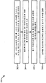
도 1 은 일반적인 음향 피드백 시나리오를 예시하는 블록도이다. 이 시나리오에서는, 잡음 마이크로폰 (noise microphone) 이 전자 회로부에 결합된다.
도 2 는 피드백 검출을 위한 시스템들 및 방법들이 구현될 수도 있는 전자 디바이스의 일 구성을 예시하는 블록도이다.
도 3 은 전자 디바이스에 의한 피드백 검출을 위한 방법의 일 구성을 예시하는 흐름도이다.
도 4 는 본원에서 개시된 시스템들 및 방법들에 따라 다수 마이크로폰 피드백 검출 시나리오의 일 예를 예시하는 블록도이다.
도 5 는 피드백 검출을 위한 시스템들 및 방법들이 구현될 수도 있는 전자 디바이스의 더욱 구체적인 구성을 예시하는 블록도이다.
도 6 은 전자 디바이스에 의한 피드백 검출을 위한 방법의 더욱 구체적인 구성을 예시하는 흐름도이다.
도 7 은 피드백 검출을 위한 시스템들 및 방법들이 구현될 수도 있는 전자 디바이스의 또 다른 더욱 구체적인 구성을 예시하는 블록도이다.
도 8 은 전자 디바이스에 의한 피드백 검출을 위한 방법의 또 다른 더욱 구체적인 구성을 예시하는 흐름도이다.
도 9 는 본원에서 개시된 시스템들 및 방법들의 성능의 예를 예시하는 그래프들을 포함한다.
도 10 은 본원에서 개시된 시스템들 및 방법들의 성능의 또 다른 예를 예시하는 그래프들을 포함한다.
도 11 은 피드백 검출을 위한 시스템들 및 방법들이 구현될 수도 있는 전자 디바이스의 또 다른 더욱 구체적인 구성을 예시하는 블록도이다.
도 12 는 피드백을 검출하기 위한 시스템들 및 방법들이 구현될 수도 있는 무선 통신 디바이스의 일 구성을 예시하는 블록도이다.
도 13 은 전자 디바이스에서 사용될 수도 있는 다양한 컴포넌트들을 예시한다.Figure 1 is a block diagram illustrating a typical acoustic feedback scenario. In this scenario, a noise microphone is coupled to the electronic circuitry.
2 is a block diagram illustrating one configuration of an electronic device in which systems and methods for feedback detection may be implemented.
3 is a flow chart illustrating one configuration of a method for feedback detection by an electronic device.
4 is a block diagram illustrating an example of multiple microphone feedback detection scenarios in accordance with the systems and methods disclosed herein.
5 is a block diagram illustrating a more specific configuration of an electronic device in which systems and methods for feedback detection may be implemented.
6 is a flow diagram illustrating a more specific configuration of a method for feedback detection by an electronic device.
7 is a block diagram illustrating another more specific configuration of an electronic device in which systems and methods for feedback detection may be implemented.
8 is a flow chart illustrating yet another more specific configuration of a method for feedback detection by an electronic device.
Figure 9 includes graphs illustrating examples of the performance of the systems and methods disclosed herein.
Figure 10 includes graphs illustrating another example of the performance of the systems and methods disclosed herein.
11 is a block diagram illustrating yet another more specific configuration of an electronic device in which systems and methods for feedback detection may be implemented.
12 is a block diagram illustrating one configuration of a wireless communication device in which systems and methods for detecting feedback may be implemented.
13 illustrates various components that may be used in an electronic device.
본원에서 개시된 시스템들 및 방법들의 일부의 구성들은 제 2 (예컨대, 에러) 마이크로폰 신호를 사용하여 음향 피드백 검출을 가능하게 한다. 음향 피드백은 트랜스듀서 (예컨대, 마이크로폰) 가 전자 신호 경로를 통해 스피커에 결합될 때에 발생할 수도 있는 문제이다. 이 설정을 갖는 시스템들의 예들은 보청기 (hearing aid) 들, 공중 방송 시스템 (public broadcast system) 들, 음성 메가폰 (voice megaphone) 들 및 능동 잡음 상쇄 (active noise cancellation; ANC) 시스템들을 포함한다.The configurations of some of the systems and methods disclosed herein enable acoustic feedback detection using a second (e.g., erroneous) microphone signal. Acoustic feedback is a problem that may occur when a transducer (e.g., a microphone) is coupled to a speaker through an electronic signal path. Examples of systems with this setting include hearing aids, public broadcast systems, voice megaphones, and active noise cancellation (ANC) systems.
능동 잡음 상쇄 애플리케이션들에서 (예컨대, 헤드셋 (headset) 들 및 핸드셋 (handset) 들에서), 환경 잡음을 픽업 (pick up) 하는 잡음 마이크로폰은, 스피커-생성된 신호가 인입하는 환경 잡음과의 상쇄 간섭 (destructive interference) 을 행하도록 신호를 프로세싱하는 전자 신호 경로를 통해 스피커에 결합된다. 이 설정은, 스피커-생성된 사운드들이 잡음 마이크로폰으로 다시 누설될 경우에 음향 피드백을 아마도 전개 (develop) 시킬 수 있다. 이 음향 피드백은 ANC 시스템들의 바람직하지 않은 아티팩트 (artifact) 이다. 따라서, 이 음향 피드백을 방지하는 것이 유익할 것이다.A noise microphone that picks up ambient noise in active noise cancellation applications (e.g., in head sets and handset sets) can be used to cancel out interference from the environment noise that the speaker- lt; RTI ID = 0.0 > destructive < / RTI > interference. This setting may possibly develop acoustic feedback in the event that the speaker-generated sounds leak back into the noise microphone. This acoustic feedback is an undesirable artifact of ANC systems. Therefore, it would be beneficial to prevent this acoustic feedback.
음향 피드백은 피드백이 발생하고 있는지 여부를 검출함으로써, 그리고 피드백 시스템의 루프 이득을 저하시킴으로써 방지될 수도 있다. 하나의 알려진 검출 접근법은 잡음 마이크로폰 신호 (예컨대, N) 와 필터링된 잡음 마이크로폰 신호 (예컨대, FpWN, 여기서 Fp 는 피드백 경로 전달 함수를 나타내고, W 는 전자 경로 전달 함수를 나타냄) 사이의 상관을 연산하는 것을 포함한다. 이 접근법에서, 음향 신호 (예컨대, X) 가 무작위 잡음 (random noise) 일 경우, 상관은 잡음 마이크로폰 신호 (예컨대, N) 에서 강력한 피드백 신호가 있을 때에 높을 것이다. 그러나, 이 상관-기반 기준은 음향 신호 (예컨대, X) 자체가 자동-상관될 때에 실패한다. 따라서, 이 접근법은 일부의 시나리오들에서 양호하게 수행되지 않을 수도 있다.Acoustic feedback may be prevented by detecting whether feedback is occurring, and by reducing the loop gain of the feedback system. One known detection approach is to use a correlation between a noise microphone signal (e.g., N) and a filtered noise microphone signal (e.g., F p WN, where F p represents the feedback path transfer function and W represents the electron path transfer function) Lt; / RTI > In this approach, if the acoustic signal (e.g., X) is a random noise, the correlation will be high when there is a strong feedback signal at the noise microphone signal (e.g., N). However, this correlation-based criterion fails when the acoustic signal (e.g., X) itself is auto-correlated. Thus, this approach may not be performed well in some scenarios.
다양한 구성들은 도면들을 참조하여 지금부터 설명되며, 여기서, 유사한 참조 번호들은 기능적으로 유사한 구성요소들을 표시할 수도 있다. 본원의 도면들에서 일반적으로 설명되고 예시된 바와 같은 시스템들 및 방법들은 폭넓게 다양한 상이한 구성들로 배열되고 설계될 수 있다. 이에 따라, 도면들에서 나타낸 바와 같이, 몇몇 구성들의 다음의 더욱 상세한 설명은 청구된 바와 같이 범위를 제한하도록 의도된 것이 아니라, 단지 시스템들 및 방법들을 대표한다.Various configurations are now described with reference to the drawings, wherein like reference numerals may refer to functionally similar components. Systems and methods, as generally described and illustrated in the Figures herein, can be arranged and designed in a wide variety of different configurations. Thus, as shown in the Figures, the following more detailed description of some configurations is not intended to limit the scope as claimed, but merely represents systems and methods.
도 1 은 일반적인 음향 피드백 시나리오를 예시하는 블록도이다. 이 시나리오에서, 잡음 마이크로폰 (102) 은 전자 회로부 (104) 에 결합된다. 전자 회로부 (104) 는 스피커 (106) 에 결합된다. 잡음 마이크로폰 (102) 은 전자 회로부를 통해 스피커 (106) 에 결합된다. 이 시나리오에서, 피드백 경로 (108) 는 스피커 (106) 와 잡음 마이크로폰 (102) 사이에 존재한다. 따라서, 스피커 (106) 에 의해 생성된 음향 신호들은 잡음 마이크로폰 (102) 에 의해 캡처될 수도 있다.Figure 1 is a block diagram illustrating a typical acoustic feedback scenario. In this scenario, the noise microphone 102 is coupled to the electronic circuitry 104. The electronic circuit portion 104 is coupled to the
피드백 검출을 위한 알려진 접근법의 일 예는 다음과 같이 주어진다. 이 예는 피드백 검출을 위한 마이크로폰 상관 접근법을 포함한다. 이 알려진 피드백 검출 및/또는 상쇄 접근법은 전자 회로부 (104) (예컨대, 전자 경로 전달 함수 W) 에 모두 접속되는 하나 이상의 잡음 마이크로폰들 (102) 을 가정한다. 마이크로폰 피드백 검출을 위한 알려진 접근법에서는, 잡음 마이크로폰 (들) (102) 으로부터 유도된 신호들 사이의 상관이 피드백 검출 방법으로서 이용된다.An example of a known approach for feedback detection is given below. This example includes a microphone correlation approach for feedback detection. This known feedback detection and / or cancellation approach assumes one or more noise microphones 102 that are all connected to electronic circuitry 104 (e. G., Electronic path transfer function W). In a known approach for microphone feedback detection, correlation between signals derived from noise microphone (s) 102 is used as a feedback detection method.
이 예에서, 피드백 경로 (108) 에 대응하는 전달 함수는 피드백 경로 전달 함수 Fp 로서 지칭될 수도 있다. 전자 회로부 (104) 에 대응하는 전달 함수는 전자 경로 전달 함수 W 로서 지칭될 수도 있다. X 는 잡음 마이크로폰 (102) 에 의해 수신되는 음향 신호 (예컨대, 환경 신호) 를 나타낸다. N 은 잡음 마이크로폰 (102) 에 의해 캡처된 입력 신호 (예컨대, 전자 신호) 를 나타낸다. 이 예에서, N = X + WFpN 이다.In this example, the transfer function corresponding to the feedback path 108 may be referred to as the feedback path transfer function F p . The transfer function corresponding to the electronic circuit portion 104 may be referred to as an electron path transfer function W. [ X represents an acoustic signal (e.g., an environmental signal) received by the noise microphone 102. N represents an input signal (e.g., an electronic signal) captured by noise microphone 102. In this example, N = X + WF p N.
이 알려진 접근법에서는, 입력 신호와 예측된 피드백 신호 사이의 상관이 계산된다. 따라서, 이 알려진 상관-기반 검출 접근법은 잡음 마이크로폰 (들) 으로부터 유도된 신호들에 오직 기초한다. 이 접근법에서는, ![]()
![]()
본원에서 개시된 시스템들 및 방법들에서는, 하나 이상의 추가적인 마이크로폰들 (예컨대, 하나 이상의 잡음 마이크로폰들을 제외한 하나 이상의 에러 마이크로폰들) 이 피드백 루프에서 포함되지 않는다. 예를 들어, 잡음 마이크로폰 (들) (102), (예를 들어, 전자 경로 전달 함수 W 를 갖는) 전자 회로부 (104), 스피커 (106), 및 피드백 경로 (108) 를 포함하는 피드백 루프 내에 있지 않은 하나 이상의 추가적인 마이크로폰들이 사용될 수도 있다. 이것은 피드백 루프에서 하나 이상의 마이크로폰들을 오직 포함할 수도 있는 알려진 접근법과는 상이하다.In the systems and methods disclosed herein, one or more additional microphones (e.g., one or more error microphones other than one or more noise microphones) are not included in the feedback loop. For example, in a feedback loop that includes noise microphone (s) 102, electronic circuitry 104 (e.g., having an electronic path transfer function W),
본원에서 개시된 시스템들 및 방법들의 일부의 구성들에서, 본원에서 개시된 시스템들 및 방법들에 따라 사용된 하나 이상의 추가적인 마이크로폰들 (예컨대, 에러 마이크로폰 (들)) 은 피드백 검출을 위하여 오직 이용될 수도 있다. 추가적으로 또는 대안적으로, 하나 이상의 추가적인 마이크로폰들에 의해 캡처된 신호 (들) 는 (예를 들어, 전자 경로 전달 함수 W 를 갖는) 전자 경로에 직접적으로 제공되지 않을 수도 있다. 예를 들어, 추가적인 마이크로폰 (들) 으로부터의 신호 (들) 는 일부의 구성들에서 피드백 (여기서, 피드백은 예를 들어, 예측되고 감산됨) 의 직접적인 상쇄를 위하여 적용되지 않을 수도 있다.In the configurations of some of the systems and methods disclosed herein, one or more additional microphones (e.g., error microphone (s)) used in accordance with the systems and methods disclosed herein may be used solely for feedback detection . Additionally or alternatively, the signal (s) captured by the one or more additional microphones may not be directly provided to the electronic path (e. G., With the electronic path transfer function W). For example, the signal (s) from the additional microphone (s) may not be applied for direct cancellation of feedback in some configurations (where feedback is predicted and subtracted, for example).
일부의 구성들에서, 본원에서 개시된 시스템들 및 방법들은 ANC 와 함께 적용될 수도 있다. 설명된 검출된 피드백은 피드포워드 ANC (그리고 예를 들어, 일부의 구성들에서는 피드백 ANC 가 아님) 에 적용될 수도 있다는 것에 주목해야 한다.In some arrangements, the systems and methods disclosed herein may be applied with ANC. It should be noted that the detected feedback described may be applied to the feedforward ANC (and, for example, not the feedback ANC in some configurations).
알려진 접근법에서는, 또 다른 마이크로폰이 스피커로부터 멀어져 있을 수도 있으므로, 피드백의 경우에 낮은 상관이 발생할 수도 있다. 더 높은 상관은 이 알려진 접근법에서의 유용한 사운드 소스와 함께 발생할 수도 있다. 그러나, 본원에서 알려진 시스템들 및 방법들은 (제 2 마이크로폰이 예를 들어, 스피커에 근접할 수도 있기 때문에) 피드백의 경우에 높은 상관을 제공할 수도 있으므로, 알려진 접근법은 본원에서 개시된 시스템들 및 방법들과는 구분된다. 또한, 본원에서 개시된 시스템들 및 방법들은 (예를 들어, 특정 프리-필터링 (pre-filtering) 으로 인해) 음향 신호의 경우에 낮은 상관을 제공할 수도 있다. 따라서, 설명된 알려진 접근법은 반대 상관 거동 (opposite correlation behavior) 을 제공하고, 본원에서 개시된 시스템들 및 방법들과는 구분된다.In a known approach, a low correlation may occur in the case of feedback, since another microphone may be away from the speaker. A higher correlation may occur with a useful sound source in this known approach. However, systems and methods known in the art may provide a high correlation in the case of feedback (because the second microphone may be close to the speaker, for example), so that a known approach may be used with systems and methods disclosed herein Respectively. In addition, the systems and methods disclosed herein may provide a low correlation in the case of acoustic signals (e.g., due to certain pre-filtering). Thus, the described known approaches provide an opposite correlation behavior and are distinct from the systems and methods disclosed herein.
또 다른 알려진 접근법은 안티-하울링 (anti-howling) 기능성을 위하여 서로에 관하여 반대-위상 (anti-phase) 으로 증폭기에 접속된 마이크로폰들을 제공한다. 이것은 지향성 마이크로폰 (directional microphone) 을 본질적으로 사용하고 있다. 이 접근법은 피드백이 상대적으로 일정할 때에 오직 유용할 수도 있다.Another known approach provides microphones connected to the amplifier in anti-phase with respect to each other for anti-howling functionality. It essentially uses directional microphones. This approach may only be useful when the feedback is relatively constant.
일부의 알려진 접근법들은 잡음 상쇄 (예컨대, 피드백 ANC) 를 위해서만 적용될 수도 있다. 이 알려진 접근법들은 피드백 ANC 를 위하여 적용되는 반면, 본원에서 개시된 시스템들 및 방법들은 피드포워드 ANC 에 적용될 수도 있으므로, 이 알려진 접근법들이 구분될 수도 있다. 추가적으로 또는 대안적으로, 본원에서 개시된 시스템들 및 방법들에서의 하나 이상의 마이크로폰들은 피드백 루프에서 포함되지 않을 수도 있는 반면, 일부의 알려진 ANC 접근법들은 피드백 루프 내에서 하나 이상의 마이크로폰들을 오직 포함한다.Some known approaches may be applied only for noise cancellation (e.g., feedback ANC). While these known approaches are applied for the feedback ANC, the systems and methods disclosed herein may be applied to the feedforward ANC so that these known approaches may be distinguished. Additionally or alternatively, one or more microphones in the systems and methods disclosed herein may not be included in the feedback loop, while some known ANC approaches only include one or more microphones in the feedback loop.
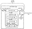
도 2 는 피드백 검출을 위한 시스템들 및 방법들이 구현될 수도 있는 전자 디바이스 (210) 의 일 구성을 예시하는 블록도이다. 전자 디바이스 (210) 의 예들은 스마트폰들, 셀룰러 전화들, 지상선 전화 (landline phone) 들, 태블릿 디바이스들, 컴퓨터들 (예컨대, 랩톱 컴퓨터들, 데스크톱 컴퓨터들 등), 헤드셋들 (예컨대, 블루투스 헤드셋들, ANC 헤드셋들, 헤드폰들 등), 음성 레코더들, 개인 정보 단말 (personal digital assistant; PDA) 들 등을 포함한다.2 is a block diagram illustrating one configuration of an electronic device 210 in which systems and methods for feedback detection may be implemented. Examples of electronic device 210 include, but are not limited to, smart phones, cellular telephones, landline phones, tablet devices, computers (e.g., laptop computers, desktop computers, etc.), headsets ANC headsets, headphones, etc.), voice recorders, personal digital assistants (PDAs), and the like.
전자 디바이스 (210) 는 하나 이상의 제 1 마이크로폰들 (212) (예컨대, 잡음 마이크로폰들), 전자 회로부 (214), 하나 이상의 스피커들 (216), 제어 회로부 (220), 및 하나 이상의 제 2 마이크로폰들 (222) (예컨대, 에러 마이크로폰들) 을 포함한다. 마이크로폰들 (212, 222) 은 음향 신호들을 전자 신호들로 변환하는 트랜스듀서 (transducer) 들일 수도 있다. 하나 이상의 스피커들 (216) 은 전자 신호들을 음향 신호들로 변환하는 트랜스듀서들일 수도 있다. 전자 회로부 (214) 는 하드웨어로, 또는 하드웨어 및 소프트웨어의 조합 (예컨대, 명령들을 갖는 프로세서) 으로 구현될 수도 있다. 제어 회로부 (220) 는 하드웨어로, 또는 하드웨어 및 소프트웨어의 조합 (예컨대, 명령들을 갖는 프로세서) 으로 구현될 수도 있다.The electronic device 210 may include one or more first microphones 212 (e.g., noise microphones), an electronic circuitry 214, one or more speakers 216, a control circuitry 220, (E. G., Error microphones). The microphones 212 and 222 may be transducers that convert acoustic signals to electronic signals. The one or more speakers 216 may be transducers that convert electronic signals to acoustic signals. The electronic circuitry 214 may be implemented in hardware, or a combination of hardware and software (e.g., a processor having instructions). The control circuitry 220 may be implemented in hardware, or in a combination of hardware and software (e.g., a processor having instructions).
하나 이상의 제 1 마이크로폰들 (212) 은 전자 회로부 (214) 및 제어 회로부 (220) 에 결합될 수도 있다. 전자 회로부 (214) 는 스피커 (216) 에 결합될 수도 있다. 제 2 마이크로폰 (222) 은 제어 회로부 (220) 에 결합될 수도 있다. 제어 회로부 (220) 는 전자 회로부 (214) 에 결합될 수도 있다. 본원에서 이용된 바와 같이, 용어 "결합" 및 관련된 용어들은 하나의 컴포넌트가 또 다른 컴포넌트에 (예를 들어, 매개 컴포넌트들 없이) 직접적으로 접속되거나 (예를 들어, 하나 이상의 매개 컴포넌트들과 함께) 간접적으로 접속된다는 것을 의미할 수도 있다. 도면들에서 도시된 화살표들 및/또는 라인들은 결합을 나타낼 수도 있다.The one or more first microphones 212 may be coupled to the electronic circuitry 214 and the control circuitry 220. Electronic circuitry 214 may also be coupled to speaker 216. The second microphone 222 may be coupled to the control circuitry 220. The control circuit unit 220 may be coupled to the electronic circuit unit 214. As used herein, the terms "coupled" and related terms are intended to encompass all types of interconnected components, whether a component is directly connected (e.g., with one or more intermediate components) It may mean that it is indirectly connected. The arrows and / or lines shown in the figures may represent a combination.
본원에서 개시된 시스템들 및 방법들은 피드백 검출에 대한 접근법을 제공한다. 이 접근법에서, (하나 이상의 제 1 마이크로폰들 (212) 로부터의) 제 1 마이크로폰 신호 (224) 및 (하나 이상의 제 2 마이크로폰들 (222) 로부터의) 제 2 마이크로폰 신호 (226) 는 상관-기반 기준들을 계산하기 위하여 사용될 수도 있다. 도 2 에서 예시된 바와 같이, 제 1 마이크로폰 (212) (예컨대, 잡음 마이크로폰) 은 전자 회로부 (214) (예컨대, 전자 경로 전달 함수 W) 를 통해 스피커 (216) 에 결합된다. 피드백 루프는 제 1 마이크로폰 (들) (212), 전자 회로부 (214) (예컨대, 전자 경로 전달 함수 W), 스피커 (216), 및 피드백 경로 (218) 를 포함할 수도 있다. 그러나, 피드백 루프는 비-피드백 경로 (232), 제 2 마이크로폰 (들) (222), 또는 제어 회로부 (220) 를 포함하지 않을 수도 있다. 하나 이상의 제 2 마이크로폰들 (222) (예컨대, 에러 마이크로폰 (들)) 은 비-피드백 경로를 통해 스피커 (216) 로부터 음향 신호들을 수신할 수도 있다.The systems and methods disclosed herein provide an approach to feedback detection. In this approach, a first microphone signal 224 (from one or more first microphones 212) and a second microphone signal 226 (from one or more second microphones 222) . ≪ / RTI > As illustrated in FIG. 2, a first microphone 212 (e.g., a noise microphone) is coupled to the speaker 216 via electronic circuitry 214 (e.g., an electronic path transfer function W). The feedback loop may include first microphone (s) 212, electronic circuitry 214 (e.g., electronic path transfer function W), speaker 216, and feedback path 218. However, the feedback loop may not include the non-feedback path 232, the second microphone (s) 222, or the control circuitry 220. One or more second microphones 222 (e.g., error microphone (s)) may receive acoustic signals from speaker 216 via a non-feedback path.
일부의 구성들에서, 제 2 마이크로폰 (222) 은 스피커 (216) 근처에 위치될 수도 있다. 예를 들어, 제 2 마이크로폰 (들) (222) (예컨대, 에러 마이크로폰 (들)) 은 제 1 마이크로폰 (들) (212) (예컨대, 잡음 마이크로폰 (들)) 보다 스피커 (216) 에 더 근접하게 위치될 수도 있다. 추가적으로 또는 대안적으로, 제 2 마이크로폰 (들) (222) 은, 양자의 스피커 (216) 및 제 2 마이크로폰 (222) 이 이용 동안에 사용자의 귓바퀴 (ear pinna) 에 의해 또는 사용자의 귓바퀴 내에서 커버 (cover) 될 정도로 충분히 근접하게, 및/또는 양자의 스피커 (216) 및 제 2 마이크로폰 (222) 이 헤드폰 또는 헤드셋 이어컵 (ear cup) 등의 내부에 있도록, 스피커 (216) 에 인접하게 위치될 수도 있다. 추가적으로 또는 대안적으로, 스피커 (216) 는 전형적으로 제 1 마이크로폰 (들) (212) 으로부터 격리될 수도 있지만, 제 2 마이크로폰 (들) (222) 으로부터 격리되지 않을 수도 있다. 예를 들어, 사용자의 귓바퀴 및/또는 전자 디바이스 (210) 의 이어컵 또는 하우징은 스피커 (216) 와 제 1 마이크로폰 (들) (212) 사이에 장벽을 제공할 수도 있다. 그러나, 스피커 (216) 와 제 1 마이크로폰 (들) (212) 사이의 격리는 일부의 경우들에는 (예컨대, 장벽이 스피커 (216) 에 의해 출력된 음향 신호들을 적절하게 감쇠시키지 않을 때에는) 파괴될 수도 있다. 본원에서 개시된 시스템들 및 방법들은 스피커 (216) 와 제 1 마이크로폰 (들) (212) 사이의 격리에 있어서의 파괴를 표시할 수도 있는 피드백이 언제 발생하는지를 검출하기 위하여 사용될 수도 있다.In some arrangements, the second microphone 222 may be located near the speaker 216. For example, the second microphone (s) 222 (e.g., error microphone (s)) may be located closer to the speaker 216 than the first microphone (s) 212 (e.g., noise microphone . Additionally or alternatively, the second microphone (s) 222 may be configured such that both the speaker 216 and the second microphone 222 are held in place by the user's ear pinna during use, or within the user ' the speaker 216 and the second microphone 222 may be positioned adjacent to the speaker 216 such that the speaker 216 and the second microphone 222 are within the headphone or headset ear cup or the like, have. Additionally or alternatively, the speaker 216 may be isolated from the first microphone (s) 212, but may not be isolated from the second microphone (s) 222. For example, a user's ear canal and / or a ear cup or housing of the electronic device 210 may provide a barrier between the speaker 216 and the first microphone (s) 212. However, isolation between the speaker 216 and the first microphone (s) 212 may be broken in some cases (e.g., when the barrier does not adequately attenuate the acoustic signals output by the speaker 216) It is possible. The systems and methods disclosed herein may be used to detect when feedback occurs that may indicate a break in isolation between the speaker 216 and the first microphone (s)
하나 이상의 제 1 마이크로폰들 (212) 은 제 1 마이크로폰 신호 (224) (예컨대, 제 1 입력 신호) 를 수신하도록 구성될 수도 있다. 예를 들어, 하나 이상의 제 1 마이크로폰 (212) 은 음향 신호들 (예컨대, 환경 사운드들, 스피커 (216) 에 의해 생성된 잡음 및/또는 신호들 등) 을 캡처할 수도 있다. 하나 이상의 제 1 마이크로폰들 (212) 은 음향 신호들을 제 1 마이크로폰 신호 (224) 예컨대, 음향 신호들에 대응하는 전자 신호) 로 변환할 수도 있다. 제 1 마이크로폰 신호 (224) 는 전자 회로부 (214) 및 제어 회로부 (220) 에 제공될 수도 있다.The one or more first microphones 212 may be configured to receive a first microphone signal 224 (e.g., a first input signal). For example, the one or more first microphones 212 may capture acoustic signals (e.g., ambient sounds, noise generated by the speaker 216 and / or signals, etc.). The one or more first microphones 212 may convert the acoustic signals into an electronic signal corresponding to the
전자 회로부 (214) 는 제 1 마이크로폰 신호 (224) 를 프로세싱할 수도 있다. 예를 들어, 전자 회로부 (214) 는 제 1 마이크로폰 신호 (224) 를 증폭할 수도 있고, 필터링할 수도 있고 (예컨대, 하나 이상의 대역들에서 이득 및/또는 감쇠를 제공하고, 지연을 추가하고, 반전하는 등), 및/또는 이와 다르게 프로세싱할 수도 있다. 전자 회로부 (214) 는 프로세싱된 제 1 마이크로폰 신호 (230) 를 스피커 (216) 에 제공할 수도 있다. 전자 회로부 (214) 의 일 예는, 스피커 (216) 에 의해 출력되는 프로세싱된 제 1 마이크로폰 신호 (230) 가 음향 신호들 및/또는 잡음을 감쇠시키거나 상쇄시키기 위하여 음향 신호들 및/또는 잡음과의 상쇄 간섭을 생성하도록, 제 1 마이크로폰 신호 (224) 를 반전시키는 ANC 회로부이다. 일부의 구성들에서, 전자 회로부 (214) 는 낮은 레이턴시 (latency) (예컨대, 5 밀리초 (ms) 이하) 를 나타낼 수도 있다.The electronic circuitry 214 may process the
일부의 구성들에서, 에코 경로 (echo path) 는 스피커 (예컨대, 스피커 (216)) 와 마이크로폰 (예컨대, 제 1 마이크로폰 (212)) 사이의 경로로서 정의될 수도 있다. 예를 들어, 에코의 경우, 마이크로폰에 의해 캡처된 입력과, 스피커에 의해 생성된 신호 사이에 더 큰 지연이 있을 수도 있다. 예를 들어, 입력 신호는 원격 장소 (예컨대, 파 엔드 (far end) 또는 저장장치) 에 제공될 수도 있다. 신호는 스피커에 제공될 수도 있는 더 큰 지연 후에 원격 장소 또는 저장장치로부터 획득될 수도 있다. 스피커에 의해 출력된 결과적인 신호가 마이크로폰에 의해 캡처될 때, 이것은 에코 경로를 통한 에코로서 지칭될 수도 있다.In some arrangements, the echo path may be defined as the path between a speaker (e.g., speaker 216) and a microphone (e.g., first microphone 212). For example, in the case of an echo, there may be a greater delay between the input captured by the microphone and the signal generated by the speaker. For example, the input signal may be provided at a remote location (e.g., a far end or a storage device). The signal may be obtained from a remote location or storage device after a larger delay that may be provided to the speaker. When the resulting signal output by the speaker is captured by the microphone, this may be referred to as echo through the echo path.
스피커 (216) 는 (예를 들어, 전자 회로부 (214) 를 통해) 제 1 마이크로폰 (들) (212) 에 결합된다. 위에서 설명된 바와 같이, 피드백 루프는 제 1 마이크로폰 (들) (212) 및 스피커 (216) 를 포함한다. 스피커 (216) 는 프로세싱된 제 1 마이크로폰 신호 (230) 에 기초하여 음향 신호를 출력할 수도 있다. 음향 신호는 비-피드백 경로 (232) 를 통해 제 2 마이크로폰 (들) (222) 으로 이동할 수도 있다. 일부의 경우들에는, 음향 신호가 피드백 경로 (218) 를 통해 제 1 마이크로폰 (들) (212) 으로 이동 (예컨대, 누설) 할 수도 있다. 예를 들어, 스피커 (216) 에 의해 출력된 음향 신호는 스피커 (216) 와 제 1 마이크로폰 (212) 사이의 격리에 있어서의 파괴가 발생할 때에 제 1 마이크로폰 (212) 으로 이동할 수도 있다.The speaker 216 is coupled to the first microphone (s) 212 (e.g., via the electronic circuitry 214). As described above, the feedback loop includes a first microphone (s) 212 and a speaker 216. The speaker 216 may output the acoustic signal based on the processed
제 2 마이크로폰 (들) (222) 은 제 2 마이크로폰 신호 (226) (예컨대, 제 2 입력 신호) 를 수신하도록 구성될 수도 있다. 예를 들어, 제 2 마이크로폰 (들) (222) 은 음향 신호들을 제 2 마이크로폰 신호 (226) (예컨대, 전자 신호) 로 변환할 수도 있다. 위에서 설명된 바와 같이, 제 2 마이크로폰 (들) (222) 은 피드백 루프의 외부에 있다 (예컨대, 피드백 루프는 제 2 마이크로폰 (들) (222) 을 포함하지 않음). 일부의 구성들에서, 제 2 마이크로폰 신호 (226) 는 피드백 상쇄 또는 감산 기법들을 위하여 적용되지 않을 수도 있다 (예컨대, 제 2 마이크로폰 신호 (226) 자체는 상쇄 간섭을 생성하기 위하여 사용되지 않을 수도 있음). 예를 들어, 제 2 마이크로폰 신호 (226) 는 일부의 구성들에서 피드백 검출을 위하여 오직 적용될 수도 있다. 제 2 마이크로폰 신호 (226) 는 제어 회로부 (220) 에 제공될 수도 있다.The second microphone (s) 222 may be configured to receive a second microphone signal 226 (e.g., a second input signal). For example, the second microphone (s) 222 may convert acoustic signals to a second microphone signal 226 (e.g., an electronic signal). As described above, the second microphone (s) 222 are external to the feedback loop (e.g., the feedback loop does not include the second microphone (s) 222). In some arrangements, the
일부의 구성들에서, 제어 회로부 (220) 는 제 1 마이크로폰 신호 (224) 에 기초하여 제 1 신호를 결정할 수도 있고, 및/또는 제 2 마이크로폰 신호 (226) 에 기초하여 제 2 신호를 결정할 수도 있다. 예를 들어, 제어 회로부 (220) 는 제 1 신호를 결정하기 위하여 제 1 마이크로폰 신호 (224) 를 필터링할 수도 있고, 및/또는 제 2 신호를 결정하기 위하여 제 2 마이크로폰 신호 (226) 를 필터링할 수도 있다. 예를 들어, 제 1 마이크로폰 신호 (224) 를 필터링하는 것은 제 1 마이크로폰 신호 (224) (또는 그 하나 이상의 대역들) 를 증폭하는 것 (예컨대, 이득을 적용함), 제 1 마이크로폰 신호 (224) (또는 그 하나 이상의 대역들) 를 감쇠시키는 것, 지연을 제 1 마이크로폰 신호 (224) 에 적용하는 것, 제 1 마이크로폰 신호 (224) 를 제 1 필터와 컨볼루션 (convolving) 하는 것, 및/또는 제 1 마이크로폰 신호 (224) 에 대해 다른 동작 (들) 을 수행하는 것을 포함할 수도 있다. 일부의 구성들에서, 제어 회로부 (220) 는 제 1 신호를 결정하기 위하여 제 1 필터에 기초하여 제 1 마이크로폰 신호 (224) 를 등화시킬 수도 있다. 예를 들어, 제어 회로부 (220) 는 제 1 신호를 결정하기 위하여, 제 1 마이크로폰 신호 (224) (예컨대, N) 를, 비-피드백 전달 함수 (예컨대, S) 에 대응하는 제 1 필터와 컨볼루션할 수도 있다. 비-피드백 전달 함수는 전자 회로부 (214) 이후로부터 스피커 (216) 를 포함하는 제 2 마이크로폰 (들) (222) 까지의 전달 함수일 수도 있다. 일부의 구성들에서, 단일-탭 필터 (single-tap filter) 는 비-피드백 전달 함수 (예컨대, S = 1) 를 모델링하기 위하여 사용될 수도 있다.In some arrangements, the control circuitry 220 may determine the first signal based on the
제 2 마이크로폰 신호 (226) 를 필터링하는 것은 제 2 마이크로폰 신호 (226) (또는 그 하나 이상의 대역들) 를 증폭하는 것 (예컨대, 이득을 적용함), 제 2 마이크로폰 신호 (226) (또는 그 하나 이상의 대역들) 를 감쇠시키는 것, 지연을 제 2 마이크로폰 신호 (226) 에 적용하는 것, 제 2 마이크로폰 신호 (226) 를 제 2 필터와 컨볼루션하는 것, 및/또는 제 2 마이크로폰 신호 (226) 에 대해 다른 동작 (들) 을 수행하는 것을 포함할 수도 있다. 일부의 구성들에서, 제어 회로부 (220) 는 제 2 신호를 결정하기 위하여 제 2 필터에 기초하여 제 2 마이크로폰 신호 (226) 를 등화시킬 수도 있다. 예를 들어, 제어 회로부 (220) 는 제 2 신호를 결정하기 위하여, 제 2 마이크로폰 신호 (226) (예컨대, E) 를, 피드백 전달 함수 (예컨대, F) 에 대응하는 제 2 필터와 컨볼루션할 수도 있다. 피드백 전달 함수는 전자 회로부 (214) 이후로부터 스피커 (216) 를 포함하지 않는 제 1 마이크로폰 (들) (212) 까지의 전달 함수일 수도 있다. 일부의 구성들에서, 단일-탭 필터는 피드백 전달 함수 (예컨대, F = -1) 를 모델링하기 위하여 사용될 수도 있다.Filtering the
(제 1 마이크로폰 신호 (224) 에 기초한) 제 1 신호와, (제 2 마이크로폰 신호 (226) 에 기초한) 제 2 신호는 피드백의 존재 시에 더 높은 상관을 나타낼 수도 있고, 피드백의 부재 시에 더 낮은 상관을 나타낼 수도 있다. 예를 들어, 제 2 마이크로폰 (222) 은 스피커 (216) 근처에 위치되므로, 제 2 신호는 피드백의 존재 시에 제 1 신호와의 더 높은 상관을 나타내는데, 이것은 스피커 (216) 에 의해 출력된 음향 신호가 제 1 마이크로폰 (212) 으로 누설될 때에 제 2 신호가 제 1 신호에 대한 유사성을 나타내기 때문이다. 이 경우, 제 1 신호 및 제 2 신호는 동일한 소스로부터 유래한 상관을 나타낸다. 그러나, 제 1 신호 및 제 2 신호는 피드백의 부재 시에 더 낮은 상관을 나타낸다. 이것은 제 1 신호 및 제 2 신호가 피드백의 부재 시에 전형적으로 유사하지 않기 때문이다.A first signal (based on the first microphone signal 224) and a second signal (based on the second microphone signal 226) may exhibit a higher correlation in the presence of feedback, It may indicate a low correlation. For example, since the second microphone 222 is located near the speaker 216, the second signal exhibits a higher correlation with the first signal in the presence of the feedback, Because when the signal leaks to the first microphone 212, the second signal shows similarity to the first signal. In this case, the first signal and the second signal represent a correlation originating from the same source. However, the first signal and the second signal exhibit a lower correlation in the absence of feedback. This is because the first signal and the second signal are typically not similar in the absence of feedback.
제어 회로부 (220) 는 제 1 마이크로폰 신호 (224) 및 제 2 마이크로폰 신호 (226) 에 기초하여 상관을 결정할 수도 있다. 예를 들어, 제어 회로부 (220) 는 (제 1 마이크로폰 신호 (224) 에 기초하는) 제 1 신호와, (제 2 마이크로폰 신호 (226) 에 기초하는) 제 2 신호 사이의 상관을 결정할 수도 있다. 일부의 구성들에서, 제어 회로부 (220) 는 제 1 신호와 제 2 신호 사이의 정규화된 상관 (normalized correlation) 을 결정할 수도 있다. 예를 들어, 제어 회로부 (220) 는 제 1 신호의 표준편차 및 제 2 신호의 표준편차에 의해 제 1 신호 및 제 2 신호의 상관을 제산 (divide) 할 수도 있다. 또 다른 예에서, 제어 회로부 (220) 는 제 2 신호의 분산 (variance) 에 의해 제 1 신호 및 제 2 신호의 상관을 제산할 수도 있다.The control circuitry 220 may determine the correlation based on the
제어 회로부 (220) 는 상관에 기초하여 (예컨대, 상관 또는 정규화된 상관에 기초하여) 피드백이 발생하고 있는지 여부를 결정할 수도 있다. 예를 들어, 제어 회로부 (220) 는 상관이 임계점을 초과할 때에 피드백이 발생하고 있는 것으로 결정할 수도 있다. 추가적으로, 제어 회로부 (220) 는 상관이 동일하거나 상이한 임계점 미만일 때에 피드백이 발생하고 있지 않은 것으로 결정할 수도 있다. 일부의 구성들에서, 제어 회로부 (220) 는 다수의 임계점들을 사용할 수도 있고, 여기서, 임계점들의 스케일 (scale) 은 피드백의 양들을 표시한다. 예를 들어, 상관이 제 1 임계점 미만일 경우, 제어 회로부 (220) 는 피드백이 발생하고 있지 않은 것으로 결정할 수도 있다. 상관이 제 1 임계점을 초과하지만, 제 2 임계점 미만일 경우, 제어 회로부 (220) 는 작은 양의 피드백이 발생하고 있는 것으로 결정할 수도 있다. 상관이 제 2 임계점을 초과할 경우, 제어 회로부 (220) 는 큰 양의 피드백이 발생하고 있는 것으로 결정할 수도 있다. 본원에서 개시된 시스템들 및 방법들에 따라 피드백이 발생하고 있는지 여부를 결정하는 것은 비-피드백 사운드 (예컨대, 음성) 를 피드백으로서 검출하는 것을 회피할 수도 있다.Control circuitry 220 may determine whether feedback is occurring (e.g., based on correlated or normalized correlations) based on the correlation. For example, the control circuitry 220 may determine that feedback is occurring when the correlation exceeds a threshold. Additionally, the control circuitry 220 may determine that feedback is not occurring when the correlation is less than or equal to a threshold. In some configurations, the control circuitry 220 may use multiple thresholds, where the scale of the thresholds represents the amount of feedback. For example, if the correlation is less than the first threshold, the control circuitry 220 may determine that feedback is not occurring. If the correlation exceeds the first threshold, but below the second threshold, the control circuitry 220 may determine that a small amount of feedback is occurring. If the correlation exceeds the second critical point, the control circuitry 220 may determine that a large amount of feedback is occurring. Determining whether feedback is occurring in accordance with the systems and methods disclosed herein may avoid detecting non-feedback sound (e.g., speech) as feedback.
제어 회로부 (220) 는 피드백이 발생하고 있을 때에 제 1 마이크로폰 신호 (224) 의 프로세싱을 조절할 수도 있다. 예를 들어, 제어 회로부 (220) 는 이득 (예컨대, 루프 이득) 을 감소시킬 수도 있고, 및/또는 피드백이 발생하고 있을 때에 피드백 루프를 접속해제할 수도 있다. 일부의 구성들에서, 제어 회로부 (220) 는 피드백이 발생하고 있는지 여부에 기초하여 제어 신호 (228) 를 생성할 수도 있다. 예를 들어, 제어 신호 (228) 는 피드백이 발생하고 있는지 여부를 표시하는 이진 표시자 (binary indicator) 를 포함할 수도 있다. 추가적으로 또는 대안적으로, 제어 신호 (228) 는 다른 제어 정보를 제공할 수도 있다. 예를 들어, 제어 신호 (228) 는 전자 회로부 (214) 로 하여금, 이득을 감소시키게 하는 전압 및/또는 전류 레벨을 변경할 수도 있다. 추가적으로 또는 대안적으로, 제어 신호 (228) 는 스위치 (예컨대, 트랜지스터) 로 하여금, 제 1 마이크로폰 (들) (212) 과 스피커 (216) 사이의 경로를 접속해제하게 하는 스위치 신호 (예컨대, 전류 또는 전압) 를 제공할 수도 있다.The control circuitry 220 may adjust the processing of the
본원에서 개시된 시스템들 및 방법들의 하나의 장점은, (피드백 루프에서의 적어도 하나의 마이크로폰 및 피드백 루프의 외부에서의 적어도 하나의 마이크로폰을 포함하는) 다수 마이크로폰-기반 피드백 검출 접근법이 음향 음성 (acoustic voice) 과 피드백 사운드들 사이의 정확한 구별을 제공한다는 것이다. 예를 들어, 본원에서 개시된 시스템들 및 방법들은 일부의 구성들에서 음성 호출 (voice call) 에서의 파-엔드 스피치 (far-end speech) 를 피드백으로서 검출하는 것을 회피할 수도 있다. (예를 들어, 피드백 루프에서 하나 이상의 마이크로폰들을 오직 사용하는) 알려진 접근법들은 인간 음성에 의해 트리거링된 많은 거짓 양성 (false positive) 들을 겪을 수도 있다.One advantage of the systems and methods disclosed herein is that multiple microphone-based feedback detection approaches (including at least one microphone in the feedback loop and at least one microphone outside the feedback loop) ) And the feedback sounds. For example, the systems and methods disclosed herein may avoid detecting far-end speech as a feedback in a voice call in some configurations. Known approaches (e.g., using only one or more microphones in the feedback loop) may experience many false positives triggered by human voice.
본원에서 개시된 시스템들 및 방법들은 또한, 제 1 마이크로폰 신호 (224) 및 제 2 마이크로폰 신호 (226) 에 의해 제공된 공간적 다이버시티 (spatial diversity) 를 사용하고, 음향 신호들과 로컬 피드백 사운드들 사이의 추가적인 구별을 제공한다. 이것은 단일 마이크로폰-기반 접근법에서는 가능하지 않다.The systems and methods disclosed herein also utilize the spatial diversity provided by the
본원에서 개시된 시스템들 및 방법들의 일부의 구성들은 핸드셋 ANC 애플리케이션들에 있어서 유용할 수도 있으며, 여기서, 제 2 마이크로폰 (222) (예컨대, 에러 마이크로폰) 은 스피커 (216) (예컨대, 리시버 (receiver)) 근처에 위치된다. 예를 들어, 스마트폰 설계는 스피커 (216) 의 (예컨대, 리시버의) 후방 측과 제 1 마이크로폰 (212) (예컨대, 잡음 마이크로폰) 사이의 옥외 경로 (open air path) 를 빈번하게 허용한다. 다양한 설계 제약들로 인해, ANC 기능성을 갖는 소형 이동 디바이스들은 스피커 (216) (예컨대, 리시버) 에 근접한 제 2 마이크로폰 (예컨대, 에러 마이크로폰) 을 가질 수도 있고, 리시버는 개선된 음향 성능을 보장하기 위하여 그 후방 측 상의 옥외 용적 (open air volume) 을 사용할 수도 있다. 본원에서 개시된 시스템들 및 방법들에 따르면, 스피커 (216) 의 후방 측은 제 2 마이크로폰 (들) (222) (예컨대, 에러 마이크로폰들) 로부터 격리될 수도 있다.The configurations of some of the systems and methods disclosed herein may be useful in handset ANC applications where a second microphone 222 (e.g., an error microphone) is coupled to a speaker 216 (e.g., a receiver) Lt; / RTI > For example, the smartphone design frequently allows an open air path between the rear side of the speaker 216 (e.g., of the receiver) and the first microphone 212 (e.g., a noise microphone). Because of various design constraints, small mobile devices with ANC functionality may have a second microphone (e. G., An error microphone) close to the speaker 216 (e. G., A receiver) and a receiver An open air volume on its rear side may also be used. According to the systems and methods disclosed herein, the rear side of the speaker 216 may be isolated from the second microphone (s) 222 (e.g., error microphones).
도 3 은 전자 디바이스 (210) 에 의한 피드백 검출을 위한 방법 (300) 의 일 구성을 예시하는 흐름도이다. 전자 디바이스 (210) 는 하나 이상의 제 1 마이크로폰들 (212) 에 의해 제 1 마이크로폰 신호 (224) 를 수신할 수도 있다 (302). 이것은 도 2 와 관련하여 위에서 설명된 바와 같이 달성될 수도 있다. 피드백 루프는 하나 이상의 제 1 마이크로폰들 (212) 및 하나 이상의 스피커들 (216) 을 포함할 수도 있다.FIG. 3 is a flow chart illustrating one configuration of a
전자 디바이스 (210) 는 피드백 루프의 외부에 있는 하나 이상의 제 2 마이크로폰들 (222) 에 의해 제 2 마이크로폰 신호 (226) 를 수신할 수도 있다 (304). 이것은 예를 들어, 도 2 와 관련하여 위에서 설명된 바와 같이 달성될 수도 있다. 제 2 마이크로폰 (들) (222) 은 스피커 (216) 근처에 위치될 수도 있다. 이것은 피드백이 발생하고 있을 때의 더 높은 상관과, 피드백이 발생하고 있지 않을 때의 더 낮은 상관의 결정을 가능하게 할 수도 있다. 위에서 설명된 바와 같이, 제 1 마이크로폰 신호 (224) 에 기초한 제 1 신호와, 제 2 마이크로폰 신호 (226) 에 기초한 제 2 신호는 피드백의 존재 시에 더 높은 상관을 나타낼 수도 있고, 피드백의 부재 시에 더 낮은 상관을 나타낼 수도 있다. 따라서, 이러한 방법으로 피드백이 발생하고 있는지 여부를 결정하는 것은 비-피드백 사운드를 피드백으로서 검출하는 것을 회피할 수도 있다.The electronic device 210 may receive the
일부의 구성들에서, 전자 디바이스 (210) 는 제 1 신호를 결정하기 위하여 제 1 마이크로폰 신호 (224) 를 필터링할 수도 있고, 제 2 신호를 결정하기 위하여 제 2 마이크로폰 신호 (226) 를 필터링할 수도 있다. 이것은 도 2 와 관련하여 위에서 설명된 바와 같이 달성될 수도 있다. 예를 들어, 제 1 마이크로폰 신호 (224) 를 필터링하는 것은 제 1 필터에 기초하여 제 1 마이크로폰 신호 (224) 를 등화시키는 것을 포함할 수도 있고, 제 2 마이크로폰 신호 (226) 를 필터링하는 것은 제 2 필터에 기초하여 제 2 마이크로폰 신호 (226) 를 등화시키는 것을 포함할 수도 있다. 특히, 제 1 필터는 비-피드백 전달 함수에 대응할 수도 있고, 제 2 필터는 피드백 전달 함수에 대응할 수도 있다.In some arrangements, the electronic device 210 may filter the
전자 디바이스 (210) 는 제 1 마이크로폰 신호 (224) 및 제 2 마이크로폰 신호 (226) 에 기초하여 상관을 결정할 수도 있다 (306). 이것은 도 2 와 관련하여 위에서 설명된 바와 같이 달성될 수도 있다. 예를 들어, 전자 디바이스 (210) 는 제 1 신호 및 제 2 신호에 기초하여 상관 (예컨대, 정규화된 상관) 을 결정할 수도 있다 (306).The electronic device 210 may determine a correlation based on the
전자 디바이스 (210) 는 상관에 기초하여 (예컨대, 상관 또는 정규화된 상관에 기초하여) 피드백이 발생하고 있는지 여부를 결정할 수도 있다 (308). 이것은 예를 들어, 도 2 와 관련하여 위에서 설명된 바와 같이 달성될 수도 있다. 일부의 구성들에서, 피드백이 발생하고 있는지 여부를 결정하는 것은 상관이 임계점을 초과할 때에 피드백이 발생하고 있는 것으로 결정하는 것, 및/또는 상관이 동일하거나 상이한 임계점 미만일 때에 피드백이 발생하고 있지 않은 것으로 결정하는 것을 포함할 수도 있다.The electronic device 210 may determine whether feedback is occurring (e.g., based on correlated or normalized correlations) based on the correlation (308). This may be accomplished, for example, as described above in connection with FIG. In some arrangements, determining whether feedback is occurring may include determining that feedback is occurring when the correlation exceeds a threshold, and / or determining that feedback is not occurring when the correlation is less than or equal to a threshold ≪ / RTI >
일부의 구성들에서, 전자 디바이스 (210) 는 피드백이 발생하고 있을 때에 제 1 마이크로폰 신호 (224) 의 프로세싱을 조절할 수도 있다. 이것은 도 2 와 관련하여 위에서 설명된 바와 같이 달성될 수도 있다. 예를 들어, 프로세싱을 조절하는 것은 이득을 감소시키는 것, 및/또는 피드백 루프를 접속해제하는 것을 포함할 수도 있다.In some arrangements, the electronic device 210 may adjust the processing of the
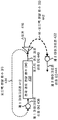
도 4 는 본원에서 개시된 시스템들 및 방법들에 따라 다수 마이크로폰 (예컨대, 듀얼 마이크로폰) 피드백 검출 시나리오의 일 예를 예시하는 블록도이다. 특히, 도 4 는 하나 이상의 제 1 마이크로폰 (412), 제 1 마이크로폰 신호 (436) (N 으로 나타냄), 전자 경로 전달 함수 (438) (W 로 나타냄), 포스트-전자 경로 신호 (post-electronic path signal; 440) (R 로 나타냄), 피드백 전달 함수 (434) (F 로 나타냄), 하나 이상의 스피커들 (416), 비-피드백 전달 함수 (442) (S 로 나타냄), 하나 이상의 제 2 마이크로폰들 (422), 및 제 2 마이크로폰 신호 (444) (E 로 나타냄) 를 예시한다. 도 4 와 관련하여 설명된 제 1 마이크로폰 (들) (412), 제 2 마이크로폰 (들) (422), 및 스피커 (들) (416) 은 도 2 와 관련하여 설명된 제 1 마이크로폰 (들) (212), 제 2 마이크로폰 (들) (222), 및 스피커 (들) (216) 에 대응할 수도 있다.4 is a block diagram illustrating an example of a multiple microphone (e.g., dual microphone) feedback detection scenario in accordance with the systems and methods disclosed herein. In particular, FIG. 4 illustrates one or more first microphone 412, first microphone signal 436 (denoted N), an electronic path transfer function 438 (denoted W), a post-electronic path signal a feedback transfer function 434 (denoted as F), one or more speakers 416, a non-feedback transfer function 442 (denoted as S), one or more second microphones A second microphone signal 422, and a second microphone signal 444 (denoted as E). The first microphone (s) 412, the second microphone (s) 422, and the speaker (s) 416 described with respect to FIG. 4 are the same as the first microphone 212, the second microphone (s) 222, and the speaker (s) 216.
전자 경로 전달 함수 (438) (W) 는 예를 들어, 도 2 와 관련하여 설명된 전자 회로부 (214) 의 응답을 모델링할 수도 있다. 포스트-전자 경로 신호 (440) (R) 는, 전자 경로 전달 함수 (438) (W) 이후이지만, 스피커 (416) 이전의 신호이다. 예를 들어, 포스트-전자 경로 신호 (440) (R) 는, 전자 경로 전달 함수 (438) (W) 로부터 출력되지만, 스피커 (416) 에 의해 출력되기 이전의 신호일 수도 있다. 포스트-전자 경로 신호 (440) (R) 로부터 (예컨대, 제 2 마이크로폰 (422) 또는 에러 마이크로폰에서의) 제 2 마이크로폰 신호 (444) (E) 까지의 전달 함수는 비-피드백 전달 함수 (442) (S) 로서 모델링될 수도 있다. 비-피드백 전달 함수 (442) (S) (예컨대, 스피커 (416) 경로에 대응하는 전달 함수) 는 스피커 (416) 를 통한 경로를 모델링할 수도 있다는 것에 주목해야 한다. 추가적으로, 포스트-전자 경로 신호 (440) (R) 로부터 (예컨대, 제 1 마이크로폰 (412) 또는 잡음 마이크로폰에서의) 제 1 마이크로폰 신호 (436) (N) 까지의 전달 함수 (예컨대, 누설) 는 피드백 전달 함수 (434) (F) 로서 모델링될 수도 있다. 피드백 전달 함수 (434) (F) 는 일부의 구성들에서 스피커 (416) 를 통한 경로를 모델링하지 않을 수도 있다는 것에 주목해야 한다. 따라서, 피드백 전달 함수 (434) (F) 는 위에서 설명된 피드백 경로 Fp 를 직접적으로 모델링할 수도 있거나 모델링하지 않을 수도 있다. 도 2 와 관련하여 위에서 설명된 바와 같이, 제 1 마이크로폰 (들) (412) 은 스피커 (들) (416) 를 갖는 피드백 루프 내에 포함될 수도 있다는 것에 주목해야 한다. 예를 들어, 제 1 마이크로폰 신호 (436) (N) (예컨대, 전자 경로 전달 함수 (438) (W) 에 의해 영향받는 바와 같은 제 1 마이크로폰 신호 (436) (N)) 의 버전은 스피커 (416) 에 의해 출력될 수도 있다. 그러나, 제 2 마이크로폰 신호 (444) (E) 자체는 예를 들어, 스피커 (416) 에 제공 (예컨대, 이를 통해 결합) 되지 않을 수도 있다. 예를 들어, 제 2 마이크로폰 신호 (444) (E) 에 기초하고 있는 별도의 제어 신호는 피드백이 발생하고 있는지 여부를 표시할 수도 있고, 및/또는 제어 정보를 제공할 수도 있다.The electronic path transfer function 438 (W) may, for example, model the response of the electronic circuitry 214 described with respect to FIG. The post-electronic path signal 440 (R) is after the electronic path transfer function 438 (W), but before the speaker 416. For example, the post-electronic path signal 440 (R) may be output from the electronic path transfer function 438 (W), but may be a signal prior to being output by the speaker 416. [ The transfer function from the post-electronic path signal 440 (R) to the second microphone signal 444 (E) (e.g., from the second microphone 422 or the error microphone) (S). ≪ / RTI > It should be noted that the non-feedback transfer function 442 (S) (e.g., the transfer function corresponding to the speaker 416 path) may also model the path through the speaker 416. In addition, the transfer function (e.g., leakage) from the post-electronic path signal 440 (R) to the first microphone signal 436 (N) (e.g., at the first microphone 412 or the noise microphone) May be modeled as a transfer function 434 (F). It should be noted that the feedback transfer function 434 (F) may not model the path through the speaker 416 in some configurations. Thus, the feedback transfer function 434 (F) may or may not directly model the feedback path F p described above. It should be noted that the first microphone (s) 412 may be included in a feedback loop having the speaker (s) 416, as described above in connection with Fig. For example, a version of a first microphone signal 436 (N) (e.g., a first microphone signal 436 (N) as affected by an electronic path transfer function 438 (W) ). ≪ / RTI > However, the second microphone signal 444 (E) itself may not be provided to (e.g., coupled to) the speaker 416, for example. For example, a separate control signal based on the second microphone signal 444 (E) may indicate whether feedback is occurring, and / or may provide control information.
제 1 마이크로폰 (412) 에 의해 수신된 제 1 마이크로폰 신호 (436) (N) 는 다음과 같이 표현될 수도 있다: N = FR. 제 2 마이크로폰 (422) 에 의해 수신된 제 2 마이크로폰 신호 (444) (E) 는 다음과 같이 표현될 수도 있다: E = SR. 따라서, FE = FSR = SN = SFR 이다. 이에 따라, FE 및 SN 의 정규화된 상관을 계산하는 것은 1 을 산출해야 한다. 예를 들어, FE 및 SN 의 정규화된 상관은 다음과 같이 표현될 수도 있다: ![]()
![]()
![]()
![]()
![]()
![]()
많은 경우들에는, 전달 함수들 F 및 S 의 간략화된 모델이 사용될 수도 있다. 일부의 구성들에서, 예를 들어, 1 탭 필터들은 F 및 S 를 모델링하기 위하여 이용될 수도 있다. 예를 들어, F = -1 및 S = 1 은 전달 함수들의 간략화된 모델로서 사용될 수도 있다. 이 구성들에서는, ![]()
![]()
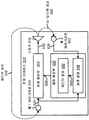
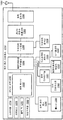
도 5 는 피드백 검출을 위한 시스템들 및 방법들이 구현될 수도 있는 전자 디바이스 (510) 의 더욱 구체적인 구성을 예시하는 블록도이다. 전자 디바이스 (510) 는 도 2 과 관련하여 설명된 전자 디바이스 (210) 의 일 예일 수도 있다. 전자 디바이스 (510) 는 하나 이상의 제 1 마이크로폰들 (512) (예컨대, 잡음 마이크로폰들), 전자 회로부 (514), 하나 이상의 스피커들 (516), 제어 회로부 (520), 및 하나 이상의 제 2 마이크로폰들 (522) (예컨대, 에러 마이크로폰들) 을 포함한다. 이 컴포넌트들 중의 하나 이상은 도 2 와 관련하여 설명된 대응하는 컴포넌트들의 예들일 수도 있다. 추가적으로, 전자 디바이스 (510) 의 컴포넌트들 중의 하나 이상은 도 2 내지 도 4 와 관련하여 설명된 기능들, 절차들, 및/또는 예들 중의 하나 이상에 따라 동작할 수도 있다.5 is a block diagram illustrating a more specific configuration of an electronic device 510 in which systems and methods for feedback detection may be implemented. The electronic device 510 may be an example of the electronic device 210 described with respect to FIG. The electronic device 510 may include one or more first microphones 512 (e.g., noise microphones), an electronic circuitry 514, one or more speakers 516, a control circuitry 520, (E. G., Error microphones). One or more of these components may be examples of corresponding components described in connection with FIG. Additionally, one or more of the components of electronic device 510 may operate in accordance with one or more of the functions, procedures, and / or examples described in connection with FIGS. 2-4.
위에서 설명된 바와 같이, 하나 이상의 제 1 마이크로폰들 (512) 은 제 1 마이크로폰 신호 (524) 를 수신하도록 구성될 수도 있다. 하나 이상의 제 1 마이크로폰들 (512) 은 음향 신호들을, 전자 회로부 (514) 및 제어 회로부 (520) 에 제공될 수도 있는 제 1 마이크로폰 신호 (524) 로 변환할 수도 있다.As described above, the one or more first microphones 512 may be configured to receive the
위에서 설명된 바와 같이, 전자 회로부 (514) 는 제 1 마이크로폰 신호 (524) 를 프로세싱할 수도 있고, 프로세싱된 제 1 마이크로폰 신호 (530) 를 스피커 (516) 에 제공할 수도 있다. 예를 들어, 전자 회로부 (514) 는 일부의 구성들에서 ANC 회로부일 수도 있다. 위에서 설명된 바와 같이, 피드백 루프는 제 1 마이크로폰 (들) (512) 및 스피커 (516) 를 포함한다. 스피커 (516) 는, 비-피드백 경로 (532) 를 통해 제 2 마이크로폰 (들) (522) 으로 이동할 수도 있고 및/또는 피드백 경로 (518) 를 통해 제 1 마이크로폰 (들) (512) 으로 이동 (예컨대, 누설) 할 수도 있는 프로세싱된 제 1 마이크로폰 신호 (530) 에 기초하여 음향 신호를 출력할 수도 있다.Electronic circuitry 514 may process
제 2 마이크로폰 (들) (522) 은, 제어 회로부 (520) 에 제공될 수도 있는 제 2 마이크로폰 신호 (526) 를 수신하도록 구성될 수도 있다. 제어 회로부 (520) 는 상관 결정 모듈 (546) 및 피드백 결정 모듈 (550) 을 포함할 수도 있다. 본원에서 이용된 바와 같이, 용어 "모듈" 은 컴포넌트가 하드웨어로, 또는 하드웨어 및 소프트웨어의 조합 (예컨대, 명령들을 갖는 프로세서) 으로 구현될 수도 있다는 것을 표시할 수도 있다.The second microphone (s) 522 may be configured to receive a
상관 결정 모듈 (546) 은 제 1 마이크로폰 신호 (524) (예컨대, 제 1 마이크로폰 신호 (524) 에 기초한 제 1 신호) 및 제 2 마이크로폰 신호 (예컨대, 제 2 마이크로폰 신호 (526) 에 기초한 제 2 신호) 를 수신할 수도 있다. 상관 결정 모듈 (546) 은 제 1 마이크로폰 신호 (524) 및 제 2 마이크로폰 신호 (526) 에 기초하여 상관 (548) (예컨대, 정규화된 상관) 을 결정할 수도 있다. 예를 들어, 상관 결정 모듈 (546) 은 (제 1 마이크로폰 신호 (524) 에 기초하는) 제 1 신호와 (제 2 마이크로폰 신호 (526) 에 기초하는) 제 2 신호 사이의 상관 (548) 을 결정할 수도 있다. 일부의 구성들에서, 상관 결정 모듈 (546) 은 제 1 신호와 제 2 신호 사이의 정규화된 상관 (548) 을 결정할 수도 있다. 예를 들어, 상관 결정 모듈 (546) 은 제 1 신호의 표준편차 및 제 2 신호의 표준편차에 의해 제 1 신호 및 제 2 신호의 상관을 제산할 수도 있다. 또 다른 예에서, 상관 결정 모듈 (546) 은 제 2 신호의 분산에 의해 제 1 신호 및 제 2 신호의 상관을 제산할 수도 있다. 상관 결정 모듈 (546) 은 상관 (548) (예컨대, 정규화된 상관 (548)) 을 피드백 결정 모듈 (550) 에 제공할 수도 있다.The correlation determination module 546 determines the correlation based on the first microphone signal 524 (e.g., the first signal based on the first microphone signal 524) and the second microphone signal (e.g., the second signal based on the second microphone signal 526) May be received. The correlation determination module 546 may determine a correlation 548 (e.g., a normalized correlation) based on the
피드백 결정 모듈 (550) 은 상관 (548) 에 기초하여 (예컨대, 상관 (548) 또는 정규화된 상관 (548) 에 기초하여) 피드백이 발생하고 있는지 여부를 결정할 수도 있다. 예를 들어, 피드백 결정 모듈 (550) 은 상관 (548) 이 임계점을 초과할 때에 피드백이 발생하고 있는 것으로 결정할 수도 있다. 추가적으로, 피드백 결정 모듈 (550) 은 상관이 동일하거나 상이한 임계점 미만일 때에 피드백이 발생하고 있지 않은 것으로 결정할 수도 있다. 일부의 구성들에서, 피드백 결정 모듈 (550) 은 다수의 임계점들을 사용할 수도 있고, 여기서, 임계점들의 스케일은 상관의 정도 또는 양을 표시한다. 예를 들어, 상관이 제 1 임계점 미만일 경우, 피드백 결정 모듈 (550) 은 피드백이 발생하고 있지 않은 것으로 결정할 수도 있다. 상관이 제 1 임계점을 초과하지만, 제 2 임계점 미만일 경우, 피드백 결정 모듈 (550) 은 작은 양의 피드백이 발생하고 있는 것으로 결정할 수도 있다. 상관이 제 2 임계점을 초과할 경우, 피드백 결정 모듈 (550) 은 큰 양의 피드백이 발생하고 있는 것으로 결정할 수도 있다. 본원에서 개시된 시스템들 및 방법들에 따라 피드백이 발생하고 있는지 여부를 결정하는 것은 비-피드백 사운드 (예컨대, 음성) 를 피드백으로서 검출하는 것을 회피할 수도 있다.The feedback determination module 550 may determine whether feedback is occurring based on the correlation 548 (e.g., based on the
제어 회로부 (520) 는 피드백이 발생하고 있을 때 (예컨대, 피드백 결정 모듈 (550) 이 피드백이 발생하고 있는 것으로 결정할 때) 에 제 1 피드백 신호 (524) 의 프로세싱을 조절할 수도 있다. 예를 들어, 제어 회로부 (520) 는 이득 (예컨대, 루프 이득) 을 감소시킬 수도 있고, 및/또는 피드백이 발생하고 있을 때에 피드백 루프를 접속해제할 수도 있다. 일부의 구성들에서, 제어 회로부 (520) 는 피드백이 발생하고 있는지 여부에 기초하여 제어 신호 (528) 를 생성할 수도 있다. 예를 들어, 제어 신호 (528) 는 피드백이 발생하고 있는지 여부를 표시하는 이진 표시자를 포함할 수도 있다. 추가적으로 또는 대안적으로, 제어 신호 (528) 는 다른 제어 정보를 제공할 수도 있다. 예를 들어, 제어 신호 (528) 는 전자 회로부 (514) 로 하여금, 이득을 감소시키게 하는 전압 및/또는 전류 레벨을 변경할 수도 있다. 추가적으로 또는 대안적으로, 제어 신호 (528) 는 스위치 (예컨대, 트랜지스터) 로 하여금, 제 1 마이크로폰 (들) (512) 과 스피커 (516) 사이의 경로를 접속해제하게 하는 스위치 신호 (예컨대, 전류 또는 전압) 를 제공할 수도 있다.The control circuitry 520 may adjust the processing of the
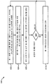
도 6 은 전자 디바이스 (510) 에 의한 피드백 검출을 위한 방법 (600) 의 더욱 구체적인 구성을 예시하는 흐름도이다. 전자 디바이스 (510) 는 하나 이상의 제 1 마이크로폰들 (512) 에 의해 제 1 마이크로폰 신호 (524) 를 수신할 수도 있다 (602). 이것은 도 2 내지 도 5 중의 하나 이상과 관련하여 위에서 설명된 바와 같이 달성될 수도 있다. 피드백 루프는 하나 이상의 제 1 마이크로폰들 (512) 및 하나 이상의 스피커들 (516) 을 포함할 수도 있다.6 is a flow chart illustrating a more specific configuration of a
전자 디바이스 (510) 는 피드백 루프의 외부에 있는 하나 이상의 제 2 마이크로폰들 (522) 에 의해 제 2 마이크로폰 신호 (526) 를 수신할 수도 있다 (604). 이것은 예를 들어, 도 2 내지 도 5 중의 하나 이상과 관련하여 위에서 설명된 바와 같이 달성될 수도 있다.The electronic device 510 may receive (604) a
전자 디바이스 (510) 는 제 1 마이크로폰 신호 (524) 및 제 2 마이크로폰 신호 (526) 에 기초하여 상관 (548) 을 결정할 수도 있다 (606). 이것은 도 2 내지 도 5 중의 하나 이상과 관련하여 위에서 설명된 바와 같이 달성될 수도 있다. 예를 들어, 전자 디바이스 (510) 는 제 1 신호 및 제 2 신호에 기초하여 상관 (548) (예컨대, 정규화된 상관 (548)) 을 결정할 수도 있다 (606).The electronic device 510 may determine 606 the
전자 디바이스 (510) 는 상관 (548) 이 임계점을 초과하는지 여부를 결정할 수도 있다 (608). 이것은 도 2 내지 도 3 및 도 5 중의 하나 이상과 관련하여 위에서 설명된 바와 같이 달성될 수도 있다. 예를 들어, 전자 디바이스 (510) (예컨대, 피드백 결정 모듈 (550)) 는 상관 (548) 이 임계점을 초과할 때에 피드백이 발생하고 있는 것으로 결정할 수도 있다. 일부의 구성들에서, 전자 디바이스 (510) (예컨대, 피드백 결정 모듈 (550)) 는 상관이 동일하거나 상이한 임계점 미만일 때에 피드백이 발생하고 있지 않은 것으로 결정할 수도 있다.The electronic device 510 may determine 608 whether the
일부의 구성들에서, 전자 디바이스 (510) 는 다수의 임계점들을 사용할 수도 있고, 여기서, 임계점들의 스케일은 상관의 정도 또는 양을 표시한다. 예를 들어, 상관이 제 1 임계점 미만일 경우, 전자 디바이스 (510) 는 피드백이 발생하고 있지 않은 것으로 결정할 수도 있다. 상관이 제 1 임계점을 초과하지만, 제 2 임계점 미만일 경우, 전자 디바이스 (510) 는 작은 양의 피드백이 발생하고 있는 것으로 결정할 수도 있다. 상관이 제 2 임계점을 초과할 경우, 전자 디바이스 (510) 는 큰 양의 피드백이 발생하고 있는 것으로 결정할 수도 있다. 일부의 구성들에서, 상관의 정도 또는 양은 제 1 마이크로폰 신호 (524) 의 프로세싱을 어떻게 조절할 것인지를 결정하기 위하여 사용될 수도 있다.In some arrangements, the electronic device 510 may use multiple thresholds, where the scale of the thresholds indicates the degree or amount of correlation. For example, if the correlation is less than the first threshold, the electronic device 510 may determine that feedback is not occurring. If the correlation exceeds the first threshold, but below the second threshold, the electronic device 510 may determine that a small amount of feedback is occurring. If the correlation exceeds the second threshold, the electronic device 510 may determine that a large amount of feedback is occurring. In some arrangements, the degree or amount of correlation may be used to determine how to process the
상관 (548) 이 임계점을 초과하지 않을 (예컨대, 그보다 더 작거나 동일함) 경우 (예컨대, 상관 (548) 이 피드백이 발생하고 있지 않는 것을 표시하는 최저 임계점을 초과하지 않을 경우), 전자 디바이스 (510) 는 방법 (600) 을 반복하기 위하여 복귀할 수도 있거나 동작이 종료될 수도 있다. 상관 (548) 이 임계점을 초과 (예컨대, 그보다 더 큼) 할 경우, 전자 디바이스 (510) 는 제 1 마이크로폰 신호의 프로세싱을 조절할 수도 있다 (610). 이것은 도 2 내지 도 3 및 도 5 중의 하나 이상과 관련하여 위에서 설명된 바와 같이 달성될 수도 있다. 예를 들어, 전자 디바이스 (예컨대, 제어 회로부 (520)) 는 이득을 감소시킴으로써, 및/또는 피드백 루프를 접속해제함으로써 프로세싱을 조절할 수도 있다 (610).(E.g., if the
일부의 구성들에서, 제 1 마이크로폰 신호 (524) 의 프로세싱을 조절하는 것 (610) 은 상관 (548) 이 (피드백의 양 또는 정도를 표시할 수도 있는) 하나 또는 다수의 임계점들을 초과하는지 여부에 기초하는 상이한 동작들을 포함할 수도 있다. 일 예에서, 상관 (548) 이 제 1 임계점을 초과하지만, (작은 양의 상관을 표시할 수도 있는) 제 2 임계점 미만일 경우, 전자 디바이스 (510) (예컨대, 제어 회로부 (520)) 는 전자 회로부 (514) 의 이득을 감소시킬 수도 있다. 상관이 제 2 임계점 (및 제 1 임계점) 을 초과할 경우, 전자 디바이스 (510) (예컨대, 제어 회로부 (520)) 는 피드백 루프를 접속해제할 수도 있다. 또 다른 예에서, 전자 디바이스 (510) (예컨대, 제어 회로부 (520)) 는 상관 (548) 이 제 1 임계점을 오직 초과할 경우에 이득을 제 1 양만큼 감소시킬 수도 있다. 추가적으로, 전자 디바이스 (510) (예컨대, 제어 회로부 (520)) 는 상관 (548) 이 (제 1 임계점보다 더 큰) 제 2 임계점을 오직 초과할 경우에 이득을 (예를 들어, 제 1 양보다 더 큰) 제 2 양만큼 감소시킬 수도 있다. 또한, 전자 디바이스 (510) (예컨대, 제어 회로부 (520)) 는 상관이 (제 1 및 제 2 임계점들보다 더 큰) 제 3 임계점을 초과할 경우에 피드백 루프를 접속해제할 수도 있다. 따라서, 전자 디바이스 (510) 는 상관의 양에 기초하여 (예컨대, 다수의 임계점들의 스케일에 관한 상관의 양에 기초하여) 프로세싱을 상이하게 (예컨대, 상이한 정도들까지, 및/또는 상이한 동작들을 이용하여) 조절할 수도 있다 (610).In some arrangements, adjusting 610 the processing of the
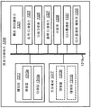
도 7 은 피드백 검출을 위한 시스템들 및 방법들이 구현될 수도 있는 전자 디바이스 (710) 의 또 다른 더욱 구체적인 구성을 예시하는 블록도이다. 전자 디바이스 (710) 는 도 2 및 도 5 와 관련하여 설명된 전자 디바이스들 (210, 510) 중의 하나 이상의 전자 디바이스의 일 예일 수도 있다. 전자 디바이스 (710) 는 하나 이상의 제 1 마이크로폰들 (712) (예컨대, 잡음 마이크로폰들), 전자 회로부 (714), 하나 이상의 스피커들 (716), 제어 회로부 (720), 및 하나 이상의 제 2 마이크로폰들 (722) (예컨대, 보조 또는 에러 마이크로폰들) 을 포함한다. 이 컴포넌트들 중의 하나 이상은 도 2 및 도 5 중의 하나 이상과 관련하여 설명된 대응하는 컴포넌트들의 예들일 수도 있다. 추가적으로, 전자 디바이스 (710) 의 컴포넌트들 중의 하나 이상은 도 2 내지 도 6 과 관련하여 설명된 기능들, 절차들, 및/또는 예들 중의 하나 이상에 따라 동작할 수도 있다.7 is a block diagram illustrating yet another more specific configuration of an electronic device 710 in which systems and methods for feedback detection may be implemented. The electronic device 710 may be an example of one or more of the electronic devices 210, 510 described with reference to FIGS. The electronic device 710 may include one or more first microphones 712 (e.g., noise microphones), an electronic circuitry 714, one or more speakers 716, a control circuitry 720, (E. G., Auxiliary or error microphones). One or more of these components may be examples of corresponding components described in connection with one or more of FIGS. 2 and 5. Additionally, one or more of the components of electronic device 710 may operate in accordance with one or more of the functions, procedures, and / or examples described in connection with FIGS. 2-6.
위에서 설명된 바와 같이, 하나 이상의 제 1 마이크로폰들 (712) 은 제 1 마이크로폰 신호 (724) 를 수신하도록 구성될 수도 있다. 제 1 마이크로폰 신호 (724) 는 전자 회로부 (714) 및 제어 회로부 (720) 에 제공될 수도 있다.As described above, the one or more first microphones 712 may be configured to receive the
위에서 설명된 바와 같이, 전자 회로부 (714) 는 제 1 마이크로폰 신호 (724) 를 프로세싱할 수도 있고, 프로세싱된 제 1 마이크로폰 신호 (730) 를 스피커 (716) 에 제공할 수도 있다. 전자 회로부 (714) 는 일부의 구성들에서 ANC 회로부일 수도 있다. 스피커 (716) 는, 비-피드백 경로 (732) 를 통해 제 2 마이크로폰 (들) (722) 으로 이동할 수도 있고 및/또는 피드백 경로 (718) 를 통해 제 1 마이크로폰 (들) (712) 으로 이동 (예컨대, 누설) 할 수도 있는 프로세싱된 제 1 마이크로폰 신호 (730) 에 기초하여 음향 신호를 출력할 수도 있다.Electronic circuitry 714 may process
제 2 마이크로폰 (들) (722) 은, 제어 회로부 (720) 에 제공될 수도 있는 제 2 마이크로폰 신호 (726) 를 수신하도록 구성될 수도 있다. 제어 회로부 (720) 는 제 1 필터 (735), 제 2 필터 (754), 상관 결정 모듈 (746), 및 피드백 결정 모듈 (750) 을 포함할 수도 있다.The second microphone (s) 722 may be configured to receive a
제 1 필터 (735) 는 제 1 마이크로폰 신호 (724) 를 수신할 수도 있다. 제 1 필터 (735) 는 제 1 신호 (752) 를 결정하기 위하여 제 1 마이크로폰 신호 (724) 를 필터링할 수도 있다. 예를 들어, 제 1 마이크로폰 신호 (724) 를 필터링하는 것은 제 1 마이크로폰 신호 (724) (또는 그 하나 이상의 대역들) 를 증폭하는 것 (예컨대, 이득을 적용함), 제 1 마이크로폰 신호 (724) (또는 그 하나 이상의 대역들) 를 감쇠시키는 것, 지연을 제 1 마이크로폰 신호 (724) 에 적용하는 것, 제 1 마이크로폰 신호 (724) 를 제 1 필터 (735) 와 컨볼루션하는 것, 및/또는 제 1 마이크로폰 신호 (724) 에 대해 다른 동작 (들) 을 수행하는 것을 포함할 수도 있다. 일부의 구성들에서, 제 1 필터 (735) 는 제 1 신호 (752) 를 결정하기 위하여 제 1 마이크로폰 신호 (724) 를 등화시킬 수도 있다. 예를 들어, 제 1 마이크로폰 신호 (724) (예컨대, N) 는 제 1 신호 (752) 를 결정하기 위하여 제 1 필터 (735) 와 컨볼루션될 수도 있다. 제 1 필터 (735) 는 비-피드백 전달 함수 (예컨대, S) 에 대응할 수도 있다. 비-피드백 전달 함수는 전자 회로부 (714) 이후의 프로세싱된 제 1 마이크로폰 신호 (예컨대, 포스트-전자 경로 신호 (R)) 로부터, 스피커 (716) 를 포함하는 제 2 마이크로폰 (들) (722) 까지의 전달 함수일 수도 있다. 따라서, 제 1 신호 (752) (예컨대, 등화된 제 1 마이크로폰 신호 (724)) 는 SN (또는 예를 들어, 그 시간-도메인 등가물) 으로서 표현될 수도 있다. 일부의 구성들에서, 제 1 필터 (735) 는 비-피드백 전달 함수 (예컨대, S = 1) 를 모델링하기 위하여 사용된 단일-탭 필터일 수도 있다. 제 1 신호 (752) 는 상관 결정 모듈 (746) 에 제공될 수도 있다.The
제 2 필터 (754) 는 제 2 마이크로폰 신호 (726) 를 수신할 수도 있다. 제 2 필터 (754) 는 제 2 신호 (756) 를 결정하기 위하여 제 2 마이크로폰 신호 (726) 를 필터링할 수도 있다. 예를 들어, 제 2 마이크로폰 신호 (726) 를 필터링하는 것은 제 2 마이크로폰 신호 (726) (또는 그 하나 이상의 대역들) 를 증폭하는 것 (예컨대, 이득을 적용함), 제 2 마이크로폰 신호 (726) (또는 그 하나 이상의 대역들) 를 감쇠시키는 것, 지연을 제 2 마이크로폰 신호 (726) 에 적용하는 것, 제 2 마이크로폰 신호 (726) 를 제 2 필터 (754) 와 컨볼루션하는 것, 및/또는 제 2 마이크로폰 신호 (726) 에 대해 다른 동작 (들) 을 수행하는 것을 포함할 수도 있다. 일부의 구성들에서, 제 2 필터 (754) 는 제 2 신호 (756) 를 결정하기 위하여 제 2 마이크로폰 신호 (726) 를 등화시킬 수도 있다. 예를 들어, 제 2 마이크로폰 신호 (726) (예컨대, E) 는 제 2 신호 (756) 를 결정하기 위하여 제 2 필터 (754) 와 컨볼루션될 수도 있다. 제 2 필터 (754) 는 피드백 전달 함수 (예컨대, F) 에 대응할 수도 있다. 피드백 전달 함수는 전자 회로부 (714) 이후의 프로세싱된 제 1 마이크로폰 신호 (예컨대, 포스트-전자 경로 신호 (R)) 로부터, 스피커 (716) 를 포함하지 않는 제 1 마이크로폰 (들) (712) 까지의 전달 함수일 수도 있다. 따라서, 제 2 신호 (756) (예컨대, 등화된 제 2 마이크로폰 신호 (726)) 는 FE (또는 예를 들어, 그 시간-도메인 등가물) 로서 표현될 수도 있다. 일부의 구성들에서, 제 2 필터 (754) 는 피드백 전달 함수 (예컨대, F = -1) 를 모델링하기 위하여 사용된 단일-탭 필터일 수도 있다. 제 2 신호 (756) 는 상관 결정 모듈 (746) 에 제공될 수도 있다.The
(제 1 마이크로폰 신호 (724) 에 기초한) 제 1 신호 (752) 와, (제 2 마이크로폰 신호 (726) 에 기초한) 제 2 신호 (756) 는 피드백의 존재 시에 더 높은 상관을 나타낼 수도 있고, 피드백의 부재 시에 더 낮은 상관을 나타낼 수도 있다. 상관 연산 전에 제 1 필터 (735) 및 제 2 필터 (754) 를 사용하는 것은 피드백 신호로부터의 음향 사운드의 구별을 위하여 유익할 수도 있다. 예를 들어, 제 1 마이크로폰 신호 (724) (예컨대, N) 를 제 1 필터 (735) (예컨대, S) 와 승산 (예컨대, 등화) 하는 것 (또는 예를 들어, 시간-도메인 등가물들을 컨볼루션하는 것) 은 제 1 신호 (752) 를 생성할 수도 있다. 또한, 제 2 마이크로폰 신호 (726) (예컨대, E) 를 제 2 필터 (735) (예컨대, F) 와 승산 (예컨대, 등화) 하는 것 (또는 예를 들어, 시간-도메인 등가물들을 컨볼루션하는 것) 은 제 2 신호 (756) 를 생성할 수도 있다. 제 1 필터 (735) 및 제 2 필터 (754) (예컨대, S 및 F 필터들) 가 없다면, 음향 사운드는 높은 상관을 더욱 빈번하게 보일 수도 있다. 이것은 피드백과 음향 사운드들 (예컨대, 음성) 사이의 구별을 더욱 어렵게 할 수도 있다.A first signal 752 (based on the first microphone signal 724) and a second signal 756 (based on the second microphone signal 726) may exhibit a higher correlation in the presence of feedback, But may exhibit a lower correlation in the absence of feedback. Using the
상관 결정 모듈 (746) 은 제 1 신호 (752) 및 제 2 신호 (756) 를 수신할 수도 있다. 상관 결정 모듈 (746) 은 제 1 신호 (752) 및 제 2 신호 (756) 에 기초하여 상관 (748) (예컨대, 정규화된 상관) 을 결정할 수도 있다. 예를 들어, 상관 결정 모듈 (746) 은 제 1 신호 (752) 와 제 2 신호 (756) 사이의 상관 (748) 을 결정할 수도 있다 (예컨대, ![]()
![]()
![]()
![]()
![]()
![]()
피드백 결정 모듈 (750) 은 상관 (748) 에 기초하여 (예컨대, 상관 (748) 또는 정규화된 상관 (748) 에 기초하여) 피드백이 발생하고 있는지 여부를 결정할 수도 있다. 예를 들어, 피드백 결정 모듈 (750) 은 상관 (748) 이 임계점을 초과할 때 (예컨대, Corr(FE, SN) > 임계점) 에 피드백이 발생하고 있는 것으로 결정할 수도 있다. 추가적으로, 피드백 결정 모듈 (750) 은 상관이 동일하거나 상이한 임계점 미만 (예컨대, 더 작거나 동일함) 일 때에 피드백이 발생하고 있지 않은 것으로 결정할 수도 있다. 일부의 구성들에서, 피드백 결정 모듈 (750) 은 다수의 임계점들을 사용할 수도 있고, 여기서, 임계점들의 스케일은 (예를 들어, 도 6 과 관련하여 위에서 설명된 바와 같이) 상관의 정도 또는 양을 표시한다.The feedback determination module 750 may determine whether feedback is occurring based on the correlation 748 (e.g., based on the
제어 회로부 (720) 는 피드백이 발생하고 있을 때 (예컨대, 상관 (748) 이 임계점을 초과할 때) 에 제 1 마이크로폰 신호 (724) 의 프로세싱을 조절할 수도 있다. 예를 들어, 제어 회로부 (720) 는 이득 (예컨대, 루프 이득) 을 감소시킬 수도 있고, 및/또는 피드백이 발생하고 있을 때에 피드백 루프를 접속해제할 수도 있다. 일부의 구성들에서, 제어 회로부 (720) 는 도 2 및 도 5 중의 하나 이상과 관련하여 위에서 설명된 바와 같이, 피드백이 발생하고 있는지 여부에 기초하여 제어 신호 (728) 를 생성할 수도 있다. 일부의 구성들에서, 제어 신호 (728) 는 위에서 설명된 바와 같이, 상관 (748) 의 양에 기초하여 상이한 동작들을 표시할 수도 있다. 예를 들어, 제어 신호 (728) 는 상관 (748) 이 제 1 임계점을 초과할 경우에 작은 이득 감소를 표시할 수도 있고, 상관 (748) 이 제 2 임계점을 초과할 경우에 더 큰 이득 감소를 표시할 수도 있고, 상관 (748) 이 제 3 임계점을 초과할 경우에 피드백 루프 접속해제를 표시할 수도 있다.Control circuitry 720 may adjust the processing of
도 8 은 전자 디바이스 (710) 에 의한 피드백 검출을 위한 방법 (800) 의 또 다른 더욱 구체적인 구성을 예시하는 흐름도이다. 전자 디바이스 (710) 는 하나 이상의 제 1 마이크로폰들 (712) 에 의해 제 1 마이크로폰 신호 (724) 를 수신할 수도 있다 (802). 이것은 도 2 내지 도 7 중의 하나 이상과 관련하여 위에서 설명된 바와 같이 달성될 수도 있다.8 is a flow chart illustrating yet another more specific configuration of a
전자 디바이스 (710) 는 피드백 루프의 외부에 있는 하나 이상의 제 2 마이크로폰들 (722) 에 의해 제 2 마이크로폰 신호 (726) 를 수신할 수도 있다 (804). 이것은 예를 들어, 도 2 내지 도 7 중의 하나 이상과 관련하여 위에서 설명된 바와 같이 달성될 수도 있다.The electronic device 710 may receive the
전자 디바이스 (710) 는 제 1 신호 (752) 를 결정하기 위하여 제 1 마이크로폰 신호 (724) 를 필터링할 수도 있다 (806). 이것은 도 2 내지 도 7 중의 하나 이상과 관련하여 위에서 설명된 바와 같이 달성될 수도 있다. 예를 들어, 제 1 마이크로폰 신호 (724) 를 필터링하는 것은 제 1 필터 (735) 에 기초하여 제 1 마이크로폰 신호 (724) 를 등화시키는 것 (예컨대, SN 을 계산하거나 그 시간-도메인 등가물들을 컨볼루션하는 것) 을 포함할 수도 있다. 특히, 제 1 필터 (735) 는 비-피드백 전달 함수에 대응할 수도 있다.The electronic device 710 may filter the
전자 디바이스 (710) 는 제 2 신호 (756) 를 결정하기 위하여 제 2 마이크로폰 신호 (726) 를 필터링할 수도 있다 (808). 이것은 도 2 내지 도 7 중의 하나 이상과 관련하여 위에서 설명된 바와 같이 달성될 수도 있다. 예를 들어, 제 2 마이크로폰 신호 (726) 를 필터링하는 것은 제 2 필터 (754) 에 기초하여 제 2 마이크로폰 신호 (726) 를 등화시키는 것 (예컨대, FE 를 계산하거나 그 시간-도메인 등가물들을 컨볼루션하는 것) 을 포함할 수도 있다. 특히, 제 2 필터 (754) 는 피드백 전달 함수에 대응할 수도 있다.The electronic device 710 may filter 808 the
전자 디바이스 (710) 는 제 1 마이크로폰 신호 (724) 및 제 2 마이크로폰 신호 (726) 에 기초하여 상관 (748) 을 결정할 수도 있다 (810). 이것은 도 2 내지 도 7 중의 하나 이상과 관련하여 위에서 설명된 바와 같이 달성될 수도 있다. 예를 들어, 전자 디바이스 (710) 는 제 1 신호 및 제 2 신호에 기초하여 상관 (748) (예컨대, 정규화된 상관 (748)) 을 결정할 수도 있다 (810). 일부의 구성들에서, 상관 (748) 을 결정하는 것 (810) 은 ![]()


![]()
전자 디바이스 (710) 는 상관 (748) 이 임계점을 초과하는지 여부를 결정할 수도 있다 (812). 이것은 도 2 내지 도 3 및 도 5 내지 도 7 중의 하나 이상과 관련하여 위에서 설명된 바와 같이 달성될 수도 있다. 예를 들어, 전자 디바이스 (710) (예컨대, 피드백 결정 모듈 (750)) 는 상관 (748) 이 임계점을 초과할 때에 피드백이 발생하고 있는 것으로 결정할 수도 있다. 일부의 구성들에서, 전자 디바이스 (710) (예컨대, 피드백 결정 모듈 (750)) 는 상관이 동일하거나 상이한 임계점 미만일 때에 피드백이 발생하고 있지 않은 것으로 결정할 수도 있다. 일부의 구성들에서, 전자 디바이스 (710) 는 위에서 설명된 바와 같이 다수의 임계점들을 사용할 수도 있다. 일부의 구성들에서, 상관의 정도 또는 양은 제 1 마이크로폰 신호 (724) 의 프로세싱을 어떻게 조절할 것인지를 결정하기 위하여 사용될 수도 있다.The electronic device 710 may determine 812 whether the
상관 (748) 이 임계점을 초과하지 않을 경우 (예컨대, 상관 (748) 이 피드백이 발생하고 있지 않는 것을 표시하는 최저 임계점 미만일 경우), 전자 디바이스 (710) 는 방법 (800) 을 반복하기 위하여 복귀할 수도 있거나 동작이 종료될 수도 있다. 상관 (748) 이 임계점을 초과할 (예컨대, 그보다 더 크거나 동일함) 경우, 전자 디바이스 (710) 는 이득 (예컨대, 루프 이득) 을 감소시킬 수도 있고 (814), 및/또는 피드백 루프를 접속해제할 수도 있다 (814). 이것은 도 2 내지 도 3 및 도 5 내지 도 7 중의 하나 이상과 관련하여 위에서 설명된 바와 같이 달성될 수도 있다. 일부의 구성들에서, 전자 디바이스 (710) 는 위에서 설명된 바와 같이, 이득을 (예를 들어, 상이한 정도들까지) 감소시킬 수도 있고 (814), 및/또는 상관의 양에 기초하여 (예컨대, 다수의 임계점들의 스케일에 관한 상관의 양에 기초하여) 피드백 루프를 접속해제할 수도 있다 (814).If the
도 9 는 본원에서 개시된 시스템들 및 방법들의 성능의 예를 예시하는 그래프들을 포함한다. 특히, 도 9 는 그래프 A (958a), 그래프 B (958b), 그래프 C (958c), 및 그래프 D (958d) 를 포함한다. 그래프들 (958a 내지 958d) 의 수평 축들의 각각은 시간 (초) 으로 예시되어 있다. 그래프 A (958a) 의 수직 축은 신호의 진폭을 예시한다. 그래프 B (958b) 의 수직 축은 또 다른 신호의 진폭을 예시한다. 그래프 C (958c) 의 수직 축은 본원에서 개시된 시스템들 및 방법들에 따라 상관을 예시한다. 그래프 D (958d) 의 수직 축은 알려진 접근법에 따라 상관을 예시한다.Figure 9 includes graphs illustrating examples of the performance of the systems and methods disclosed herein. In particular, FIG. 9 includes
그래프 A (958a) 는 시간에 대한 신호를 예시한다. 특히, 그래프 A (958a) 는 필터링된 제 1 마이크로폰 신호 (예컨대, 필터링된 잡음 마이크로폰 신호) 의 일 예를 예시하고, 여기서, 피드백 (960) 은 대략 0 및 3.5 초 사이에서 발생하고, 여기서, 음성 (962) 은 대략 5 및 7 초 사이에서 수신된다. 더욱 구체적으로, 그래프 A (958a) 에서 도시된 파형은 도 7 과 관련하여 위에서 설명된 제 1 신호 (752) (예컨대, SN) 의 일 예일 수도 있다.Graph A 958a illustrates a signal for time. In particular,
그래프 B (958b) 는 시간에 대한 또 다른 신호를 예시한다. 특히, 그래프 B (958b) 는 필터링된 제 2 마이크로폰 신호 (예컨대, 필터링된 에러 마이크로폰 신호) 의 일 예를 예시하고, 여기서, 피드백 (960) 은 대략 0 및 3.5 초 사이에서 발생하고, 여기서, 음성 (962) 은 대략 5 및 7 초 사이에서 수신된다. 더욱 구체적으로, 그래프 B (958b) 에서 도시된 파형은 도 7 과 관련하여 위에서 설명된 제 2 신호 (756) (예컨대, FE) 의 일 예일 수도 있다.
그래프 C (958c) 는 본원에서 개시된 시스템들 및 방법들에 따라 상관 (예컨대, ![]()
![]()
그래프 D (958d) 는 하나의 알려진 접근법에 따라 상관 (예컨대, ![]()
![]()
도 10 은 본원에서 개시된 시스템들 및 방법들의 성능의 또 다른 예를 예시하는 그래프들을 포함한다. 특히, 도 10 은 그래프 A (1058a), 그래프 B (1058b), 그래프 C (1058c), 및 그래프 D (1058d) 를 포함한다. 그래프들 (1058a 내지 1058d) 의 수평 축들의 각각은 시간 (초) 으로 예시되어 있다. 그래프 A (1058a) 의 수직 축은 신호의 진폭을 예시한다. 그래프 B (1058b) 의 수직 축은 또 다른 신호의 진폭을 예시한다. 그래프 C (1058c) 의 수직 축은 본원에서 개시된 시스템들 및 방법들에 따라 상관을 예시한다. 그래프 D (1058d) 의 수직 축은 알려진 접근법에 따라 상관을 예시한다.Figure 10 includes graphs illustrating another example of the performance of the systems and methods disclosed herein. In particular, FIG. 10 includes
그래프 A (1058a) 는 시간에 대한 신호를 예시한다. 특히, 그래프 A (1058a) 는 필터링된 제 1 마이크로폰 신호 (예컨대, 필터링된 잡음 마이크로폰 신호) 의 또 다른 예를 예시하고, 여기서, 음성 (1062) 은 대략 0 및 33 초 사이에서 수신되고, 여기서, 음성 및 잡음 (1066) 은 대략 33 및 77 초 사이에서 수신되고, 여기서, 피드백 (1060) 은 대략 78 및 111 초 사이에서 발생한다. 더욱 구체적으로, 그래프 A (1058a) 에서 도시된 파형은 도 7 과 관련하여 위에서 설명된 제 1 신호 (752) (예컨대, SN) 의 일 예일 수도 있다.Graph A 1058a illustrates the signal over time. In particular,
그래프 B (1058b) 는 시간에 대한 또 다른 신호를 예시한다. 특히, 그래프 B (1058a) 는 필터링된 제 2 마이크로폰 신호 (예컨대, 필터링된 에러 마이크로폰 신호) 의 또 다른 예를 예시하고, 여기서, 음성 (1062) 은 대략 0 및 33 초 사이에서 수신되고, 여기서, 음성 및 잡음 (1066) 은 대략 33 및 77 초 사이에서 수신되고, 여기서, 피드백 (1060) 은 대략 78 및 111 초 사이에서 발생한다. 더욱 구체적으로, 그래프 B (1058b) 에서 도시된 파형은 도 7 과 관련하여 위에서 설명된 제 2 신호 (756) (예컨대, FE) 의 일 예일 수도 있다.Graph B 1058b illustrates another signal for time. In particular,
그래프 C (1058c) 는 본원에서 개시된 시스템들 및 방법들에 따라 상관 (예컨대, ![]()


![]()
그래프 D (1058d) 는 하나의 알려진 접근법에 따라 상관 (예컨대, 
도 11 은 피드백 검출을 위한 시스템들 및 방법들이 구현될 수도 있는 전자 디바이스 (1110) 의 또 다른 더욱 구체적인 구성 (예컨대, 핸드셋 ANC 애플리케이션 시나리오) 을 예시하는 블록도이다. 전자 디바이스 (1110) 는 도 2, 도 5, 및 도 7 과 관련하여 설명된 전자 디바이스들 (210, 510, 710) 중의 하나 이상의 전자 디바이스의 일 예일 수도 있다. 예를 들어, 전자 디바이스 (1110) 는 스마트폰 또는 셀룰러 전화와 같은 핸드셋일 수도 있다. 전자 디바이스 (1110) 는 하나 이상의 제 1 마이크로폰들 (1112) (예컨대, 잡음 마이크로폰들), 능동 잡음 상쇄기 (1114), 하나 이상의 스피커들 (1116) (예컨대, 리시버들), 제어 회로부 (1120), 및 하나 이상의 제 2 마이크로폰들 (1122) (예컨대, 보조 또는 에러 마이크로폰들) 을 포함한다. 이 컴포넌트들 중의 하나 이상은 도 2, 도 5, 및 도 7 중의 하나 이상과 관련하여 설명된 대응하는 컴포넌트들의 예들일 수도 있다. 추가적으로, 전자 디바이스 (1110) 의 컴포넌트들 중의 하나 이상은 도 2 내지 도 8 과 관련하여 설명된 기능들, 절차들, 및/또는 예들 중의 하나 이상에 따라 동작할 수도 있다.11 is a block diagram illustrating another more specific configuration (e.g., a handset ANC application scenario) of an electronic device 1110 in which systems and methods for feedback detection may be implemented. The electronic device 1110 may be an example of one or more of the electronic devices 210, 510, 710 described with reference to Figures 2, 5, and 7. For example, the electronic device 1110 may be a handset such as a smart phone or a cellular telephone. Electronic device 1110 includes one or more first microphones 1112 (e.g., noise microphones), active noise canceller 1114, one or more speakers 1116 (e.g., receivers),
이 예에서, 제 2 마이크로폰 (들) (1122) 은 스피커 (1116) 근처에 위치된다. 본원에서 개시된 시스템들 및 방법들과 일부의 알려진 접근법들 사이의 하나의 차이는 여분의 마이크로폰 (예컨대, 하나 이상의 제 2 마이크로폰들 (1122)) 의 사용이다.In this example, the second microphone (s) 1122 is located near the speaker 1116. One difference between the systems and methods disclosed herein and some known approaches is the use of redundant microphones (e.g., one or more second microphones 1122).
일부의 구성들에서, 제 1 마이크로폰 (들) (1112) 은 스피커 (1116) 및/또는 제 2 마이크로폰 (들) (1122) 로부터 멀어지도록 위치될 수도 있다. 예를 들어, 제 1 마이크로폰 (들) (1112) 은 전자 디바이스 (1110) 의 후방 상에 (예컨대, 스피커 (들) (1116) 및/또는 제 2 마이크로폰 (들) (1122) 으로부터 반대 측 상에) 위치될 수도 있다. 추가적으로 또는 대안적으로, 제 1 마이크로폰 (들) (1112) 은 격리 (1170) 의 외부에 위치될 수도 있는 반면, 제 2 마이크로폰 (들) (1122) 은 전형적으로 격리 (1170) 의 내부에 위치될 수도 있다.In some arrangements, the first microphone (s) 1112 may be positioned away from the speaker 1116 and / or the second microphone (s) 1122. For example, the first microphone (s) 1112 may be disposed on the rear side of the electronic device 1110 (e.g., from the speaker (s) 1116 and / or the second microphone (s) ). Additionally or alternatively, the first microphone (s) 1112 may be located external to the isolation 1170 while the second microphone (s) 1122 are typically located within the isolation 1170 It is possible.
위에서 설명된 바와 같이, 하나 이상의 제 1 마이크로폰들 (1112) 은 제 1 마이크로폰 신호 (1124) 를 수신하도록 구성될 수도 있다. 제 1 마이크로폰 신호 (1124) 는 능동 잡음 상쇄기 (1114) 및 제어 회로부 (1120) 에 제공될 수도 있다. 능동 잡음 상쇄기 (1114) 는 제 1 마이크로폰 (들) (1112) (예컨대, 환경 사운드들) 에 의해 캡처된 음향 신호들 및/또는 잡음의 상쇄 간섭 및/또는 감소를 생성하기 위하여 사용되는 프로세싱된 제 1 마이크로폰 신호 (1130) 를 생성할 수도 있다. 프로세싱된 제 1 마이크로폰 신호 (1130) 는 스피커 (1116) 에 제공될 수도 있다. 스피커 (1116) 는, 격리 (1170) 에 있어서의 파괴가 발생할 때에 제 2 마이크로폰 (들) (1122) 로 이동할 수도 있고 및/또는 제 1 마이크로폰 (들) (1112) 으로 이동 (예컨대, 누설) 할 수도 있는 프로세싱된 제 1 마이크로폰 신호 (1130) 에 기초하여 음향 신호를 출력할 수도 있다. 격리 (1170) 는 사용자가 전자 디바이스 (1110) 를 그/그녀의 귀 (1168) 에 가압함으로써 생성될 수도 있거나, 전자 디바이스 (1110) 의 이어컵 또는 하우징에 의해 생성될 수도 있다.As described above, the one or more first microphones 1112 may be configured to receive the
제 2 마이크로폰 (들) (1122) 은, 제어 회로부 (1120) 에 제공될 수도 있는 제 2 마이크로폰 신호 (1126) 를 수신하도록 구성될 수도 있다. 제어 회로부 (1120) 는 도 2 내지 도 8 중의 하나 이상과 관련하여 설명된 바와 같이, 제 1 마이크로폰 신호 (1124) 를 필터링할 수도 있고, 제 2 마이크로폰 신호 (1126) 를 필터링할 수도 있고, 상관을 결정할 수도 있고, 상관에 기초하여 피드백이 발생하고 있는지 여부를 결정할 수도 있고, 및/또는 (예를 들어, 제어 신호 (1128) 를 통해) 프로세싱을 조절할 수도 있다. 예를 들어, 제어 회로부 (1120) 는 능동 잡음 상쇄기 (1114) 의 이득 (예컨대, 루프 이득) 을 감소시킬 수도 있고, 및/또는 피드백이 발생하고 있을 때에 능동 잡음 상쇄기 (1114) 에서 피드백 루프를 접속해제할 수도 있다.The second microphone (s) 1122 may be configured to receive a
도 12 는 피드백을 검출하기 위한 시스템들 및 방법들이 구현될 수도 있는 무선 통신 디바이스 (1210) 의 일 구성을 예시하는 블록도이다. 도 12 에서 예시된 무선 통신 디바이스 (1210) 는 본원에서 설명된 전자 디바이스들 (210, 510, 710, 1110) 중의 하나 이상의 전자 디바이스의 예일 수도 있다. 무선 통신 디바이스 (1210) 는 애플리케이션 프로세서 (1284) 를 포함할 수도 있다. 애플리케이션 프로세서 (1284) 는 일반적으로 무선 통신 디바이스 (1210) 상에서 기능들을 수행하기 위하여 명령들을 프로세싱한다 (예컨대, 프로그램들을 실행함). 애플리케이션 프로세서 (1284) 는 오디오 코더/디코더 (coder/decoder; codec)(코덱) (1282) 에 결합될 수도 있다.12 is a block diagram illustrating one configuration of a wireless communication device 1210 in which systems and methods for detecting feedback may be implemented. The wireless communication device 1210 illustrated in FIG. 12 may be an example of one or more of the electronic devices 210, 510, 710, 1110 described herein. The wireless communication device 1210 may include an
오디오 코덱 (1282) 은 오디오 신호들을 코딩 및/또는 디코딩하기 위하여 이용될 수도 있다. 오디오 코덱 (1282) 은 적어도 하나의 스피커 (1274), 이어피스 (earpiece; 1276), 출력 잭 (1278), 및/또는 적어도 하나의 마이크로폰 (1280) 에 결합될 수도 있다. 스피커들 (1274) 은 전기 또는 전자 신호들을 음향 신호들로 변환하는 하나 이상의 전기-음향 트랜스듀서 (electro-acoustic transducer) 들을 포함할 수도 있다. 예를 들어, 스피커들 (1274) 은 음악을 재생하거나 또는 스피커폰 대화를 출력하는 등을 하기 위하여 이용될 수도 있다. 이어피스 (1276) 는 음향 신호들 (예컨대, 스피치 신호들) 을 사용자에게 출력하기 위하여 이용될 수 있는 또 다른 스피커 또는 전기-음향 트랜스듀서일 수도 있다. 예를 들어, 이어피스 (1276) 는 사용자만이 음향 신호를 신뢰성있게 청취할 수 있도록 이용될 수도 있다. 출력 잭 (1278) 은 다른 디바이스들을, 헤드폰들과 같이, 오디오를 출력하기 위한 무선 통신 디바이스 (1210) 에 결합하기 위하여 이용될 수도 있다. 스피커들 (1274), 이어피스 (1276), 및/또는 출력 잭 (1278) 은 일반적으로 오디오 코덱 (1282) 으로부터 오디오 신호를 출력하기 위하여 이용될 수도 있다. 적어도 하나의 마이크로폰 (1280) 은 (사용자의 음성과 같은) 음향 신호를, 오디오 코덱 (1282) 에 제공되는 전기 또는 전자 신호들로 변환하는 음향-전기 트랜스듀서 (acousto-electric transducer) 일 수도 있다.The audio codec 1282 may be used for coding and / or decoding audio signals. The audio codec 1282 may be coupled to at least one speaker 1274, earpiece 1276, output jack 1278, and / or at least one microphone 1280. Speakers 1274 may include one or more electro-acoustic transducers that convert electrical or electronic signals to acoustic signals. For example, speakers 1274 may be used to play music, or to output speakerphone conversations, and the like. Earpiece 1276 may be another speaker or electro-acoustic transducer that may be utilized to output acoustic signals (e.g., speech signals) to a user. For example, the earpiece 1276 may be utilized so that only the user can reliably listen to the acoustic signal. The output jack 1278 may be used to couple other devices to the wireless communication device 1210 for outputting audio, such as headphones. Speakers 1274, earpiece 1276, and / or output jack 1278 may also be used to output audio signals from audio codec 1282 in general. The at least one microphone 1280 may be an acousto-electric transducer that converts an acoustic signal (such as a user's voice) into electrical or electronic signals provided to the audio codec 1282.
오디오 코덱 (1282) 은 제어 회로부 (1220) 를 포함할 수도 있다. 제어 회로부 (1220) 는 위에서 설명된 제어 회로부들 (220, 520, 720, 1120) 중의 하나 이상의 제어 회로부의 예일 수도 있다. 일부의 구성들에서, 제어 회로부 (1220) 는 오디오 코덱 (1282) 과는 별도로 무선 통신 디바이스 (1210) 상에서 구현될 수도 있다.Audio codec 1282 may include
애플리케이션 프로세서 (1284) 는 또한, 전력 관리 회로 (1294) 에 결합될 수도 있다. 전력 관리 회로 (1294) 의 일 예는, 무선 통신 디바이스 (1210) 의 전기적 전력 소비를 관리하기 위하여 이용될 수도 있는 전력 관리 집적 회로 (power management integrated circuit; PMIC) 이다. 전력 관리 회로 (1294) 는 배터리 (1296) 에 결합될 수도 있다. 배터리 (1296) 는 일반적으로 전력을 무선 통신 디바이스 (1210) 에 제공할 수도 있다. 예를 들어, 배터리 (1296) 및/또는 전력 관리 회로 (1294) 는 무선 통신 디바이스 (1210) 내에 포함된 엘리먼트들 중의 적어도 하나에 결합될 수도 있다.The
애플리케이션 프로세서 (1284) 는 입력을 수신하기 위한 적어도 하나의 입력 디바이스 (1298) 에 결합될 수도 있다. 입력 디바이스들 (1298) 의 예들은 적외선 센서들, 이미지 센서들, 가속도계들, 터치 센서들, 키패드들 등을 포함한다. 입력 디바이스들 (1298) 은 무선 통신 디바이스 (1210) 와의 사용자 상호작용을 허용할 수도 있다. 애플리케이션 프로세서 (1284) 는 또한, 하나 이상의 출력 디바이스들 (1201) 에 결합될 수도 있다. 출력 디바이스들 (1201) 의 예들은 프린터들, 프로젝터 (projector) 들, 스크린들, 햅틱 디바이스 (haptic device) 들 등을 포함한다. 출력 디바이스들 (1201) 은 무선 통신 디바이스 (1210) 가 사용자에 의해 경험될 수도 있는 출력을 생성하도록 할 수도 있다.The
애플리케이션 프로세서 (1284) 는 애플리케이션 메모리 (1203) 에 결합될 수도 있다. 애플리케이션 메모리 (1203) 는 전자 정보를 저장할 수 있는 임의의 전자 디바이스일 수도 있다. 애플리케이션 메모리 (1203) 의 예들은 이중 데이터 레이트 동기식 동적 랜덤 액세스 메모리 (double data rate synchronous dynamic random access memory; DDRAM), 동기식 동적 랜덤 액세스 메모리 (synchronous dynamic random access memory; SDRAM), 플래시 메모리 등을 포함한다. 애플리케이션 메모리 (1203) 는 애플리케이션 프로세서 (1284) 를 위한 저장을 제공할 수도 있다. 예를 들어, 애플리케이션 메모리 (1203) 는 애플리케이션 프로세서 (1284) 상에서 실행되는 프로그램들의 기능을 위한 데이터 및/또는 명령들을 저장할 수도 있다.The
애플리케이션 프로세서 (1284) 는 디스플레이 제어기 (1205) 에 결합될 수도 있고, 이 디스플레이 제어기 (1205) 는 궁극적으로 디스플레이 (1207) 에 결합될 수도 있다. 디스플레이 제어기 (1205) 는 디스플레이 (1207) 상에서 이미지들을 생성하기 위하여 이용되는 하드웨어 블록일 수도 있다. 예를 들어, 디스플레이 제어기 (1205) 는 애플리케이션 프로세서 (1284) 로부터의 명령들 및/또는 데이터를, 디스플레이 (1207) 상에서 제시될 수 있는 이미지들로 변환할 수도 있다. 디스플레이 (1207) 의 예들은 액정 디스플레이 (liquid crystal display; LCD) 패널들, 발광 다이오드 (light emitting diode; LED) 패널들, 음극선관 (cathode ray tube; CRT) 디스플레이들, 플라즈마 디스플레이들 등을 포함한다.The
애플리케이션 프로세서 (1284) 는 기저대역 프로세서 (1286) 에 결합될 수도 있다. 기저대역 프로세서 (1286) 는 일반적으로 통신 신호들을 프로세싱한다. 예를 들어, 기저대역 프로세서 (1286) 는 수신된 신호들을 복조 및/또는 디코딩할 수도 있다. 추가적으로 또는 대안적으로, 기저대역 프로세서 (1286) 는 송신을 위한 준비로 신호들을 인코딩 및/또는 변조할 수도 있다.The
기저대역 프로세서 (1286) 는 기저대역 메모리 (1209) 에 결합될 수도 있다. 기저대역 메모리 (1209) 는 SDRAM, DDRAM, 플래시 메모리 등과 같이, 전자 정보를 저장할 수 있는 임의의 전자 디바이스일 수도 있다. 기저대역 프로세서 (1286) 는 기저대역 메모리 (1209) 로부터 정보 (예컨대, 명령들 및/또는 데이터) 를 판독할 수도 있고, 및/또는 정보를 기저대역 메모리 (3766) 에 기록할 수도 있다. 추가적으로 또는 대안적으로, 기저대역 프로세서 (1286) 는 통신 동작들을 수행하기 위하여 기저대역 메모리 (1209) 내에 저장된 명령들 및/또는 데이터를 이용할 수도 있다.Baseband processor 1286 may be coupled to baseband memory 1209. [ The baseband memory 1209 may be any electronic device capable of storing electronic information, such as SDRAM, DDRAM, flash memory, and the like. Baseband processor 1286 may read information (e.g., instructions and / or data) from baseband memory 1209 and / or write information to baseband memory 3766. Additionally or alternatively, the baseband processor 1286 may utilize the instructions and / or data stored in the baseband memory 1209 to perform communication operations.
기저대역 프로세서 (1286) 는 라디오 주파수 (radio frequency; RF) 트랜시버 (1288) 에 결합될 수도 있다. RF 트랜시버 (1288) 는 전력 증폭기 (1290) 및 하나 이상의 안테나들 (1292) 에 결합될 수도 있다. RF 트랜시버 (1288) 는 라디오 주파수 신호들을 송신 및/또는 수신할 수도 있다. 예를 들어, RF 트랜시버 (1288) 는 전력 증폭기 (1290) 및 적어도 하나의 안테나 (1292) 를 이용하여 RF 신호를 송신할 수도 있다. RF 트랜시버 (1288) 는 또한, 하나 이상의 안테나들 (1292) 을 이용하여 RF 신호들을 수신할 수도 있다.The baseband processor 1286 may be coupled to a radio frequency (RF) transceiver 1288. The RF transceiver 1288 may be coupled to a power amplifier 1290 and one or
도 13 은 전자 디바이스 (1310) 에서 이용될 수도 있는 다양한 컴포넌트들을 예시한다. 예시된 컴포넌트들은 동일한 물리적인 구조 내에서 또는 별도의 하우징들 또는 구조들에서 위치될 수도 있다. 도 13 과 관련하여 설명된 전자 디바이스 (1310) 는 본원에서 설명된 전자 디바이스들 (210, 510, 710, 1110) 및 무선 통신 디바이스 (1210) 중의 하나 이상에 따라 구현될 수도 있다. 전자 디바이스 (1310) 는 프로세서 (1317) 를 포함한다. 프로세서 (1317) 는 범용 단일-칩 또는 멀티-칩 마이크로프로세서 (예컨대, ARM), 특수 목적 마이크로프로세서 (예컨대, 디지털 신호 프로세서 (digital signal processor; DSP)), 마이크로제어기, 프로그래밍가능 게이트 어레이 등일 수도 있다. 프로세서 (1317) 는 중앙 프로세싱 유닛 (central processing unit; CPU) 으로서 지칭될 수도 있다. 단지 단일 프로세서 (1317) 가 도 13 의 전자 디바이스 (1310) 에서 도시되어 있지만, 대안적인 구성에서는, 프로세서들 (예컨대, ARM 및 DSP) 의 조합이 이용될 수 있다.13 illustrates various components that may be utilized in electronic device 1310. [ The illustrated components may be located within the same physical structure or in separate housings or structures. The electronic device 1310 described in connection with FIG. 13 may be implemented according to one or more of the electronic devices 210, 510, 710, 1110 and the wireless communication device 1210 described herein. The electronic device 1310 includes a processor 1317. Processor 1317 may be a general purpose single-chip or multi-chip microprocessor (e.g., an ARM), a special purpose microprocessor (e.g., a digital signal processor (DSP)), a microcontroller, a programmable gate array, . Processor 1317 may be referred to as a central processing unit (CPU). Although only a single processor 1317 is shown in the electronic device 1310 of FIG. 13, in an alternative configuration, a combination of processors (e.g., ARM and DSP) may be used.
전자 디바이스 (1310) 는 또한, 프로세서 (1317) 와 전자 통신하는 메모리 (1311) 를 포함한다. 즉, 프로세서 (1317) 는 메모리 (1311) 로부터 정보를 판독할 수 있고, 및/또는 정보를 메모리 (1667) 에 기록할 수 있다. 메모리 (1311) 는 전자 정보를 저장할 수 있는 임의의 전자 컴포넌트일 수도 있다. 메모리 (1311) 는 랜덤 액세스 메모리 (random access memory; RAM), 판독-전용 메모리 (read-only memory; ROM), 자기디스크 저장 매체들, 광학 저장 매체들, RAM 에서의 플래시 메모리 디바이스들, 프로세서와 함께 포함된 온-보드 메모리 (on-board memory), 프로그래밍가능 판독-전용 메모리 (programmable read-only memory; PROM), 소거가능 프로그래밍가능 판독-전용 메모리 (erasable programmable read-only memory; EPROM), 전기적 소거가능 PROM (electrically erasable PROM; EEPROM), 레지스터들, 및 그 조합들을 포함하는 기타 등등일 수도 있다.The electronic device 1310 also includes a memory 1311 in electronic communication with the processor 1317. That is, processor 1317 may read information from memory 1311 and / or write information to memory 1667. The memory 1311 may be any electronic component capable of storing electronic information. The memory 1311 may be a random access memory (RAM), a read-only memory (ROM), magnetic disk storage media, optical storage media, flash memory devices in RAM, On-board memory, programmable read-only memory (PROM), erasable programmable read-only memory (EPROM), electrically programmable read-only memory An electrically erasable PROM (EEPROM), registers, and the like, including combinations thereof, and the like.
데이터 (1315a) 및 명령들 (1313a) 은 메모리 (1311) 내에 저장될 수도 있다. 명령들 (1313a) 은 하나 이상의 프로그램들, 루틴들, 서브-루틴들, 함수들, 절차들 등을 포함할 수도 있다. 명령들 (1313a) 은 단일 컴퓨터-판독가능 스테이트먼트 (statement) 또는 다수의 컴퓨터-판독가능 스테이트먼트들을 포함할 수도 있다. 명령들 (1313a) 은 위에서 설명된 방법들, 기능들, 및 절차들 중의 하나 이상을 구현하기 위하여 프로세서 (1317) 에 의해 실행가능할 수도 있다. 명령들 (1313a) 을 실행하는 것은 메모리 (1311) 내에 저장되는 데이터 (1315a) 의 이용을 수반할 수도 있다. 도 13 은 (명령들 (1313a) 및 데이터 (1315a) 로부터 유래될 수도 있는) 프로세서 (1317) 로 로딩되는 일부의 명령들 (1313b) 및 데이터 (1315b) 를 도시한다.Data 1315a and
전자 디바이스 (1310) 는 또한, 다른 전자 디바이스들과 통신하기 위한 하나 이상의 통신 인터페이스들 (1321) 을 포함할 수도 있다. 통신 인터페이스들 (1321) 은 유선 통신 기술, 무선 통신 기술, 또는 양자에 기초할 수도 있다. 상이한 타입들의 통신 인터페이스들 (1321) 의 예들은 직렬 포트, 병렬 포트, 유니버셜 직렬 버스 (Universal Serial Bus; USB), 이더넷 어댑터 (Ethernet adapter), 국제 전기전자 기술자 협회 (Institute of Electrical and Electronics Engineers; IEEE) 1394 버스 인터페이스, 소형 컴퓨터 시스템 인터페이스 (small computer system interface; SCSI) 버스 인터페이스, 적외선 (infrared; IR) 통신 포트, Bluetooth 무선 통신 어댑터, 3 세대 파트너십 프로젝트 (3rd Generation Partnership Project; 3GPP) 트랜시버, IEEE 802.11 ("Wi-Fi") 트랜시버, 및 기타 등등을 포함한다. 예를 들어, 통신 인터페이스 (1321) 는 무선 신호들을 송신하고 수신하기 위한 하나 이상의 안테나들 (도시되지 않음) 에 결합될 수도 있다.The electronic device 1310 may also include one or more communication interfaces 1321 for communicating with other electronic devices. Communication interfaces 1321 may be based on wired communication technology, wireless communication technology, or both. Examples of the different types of communication interfaces 1321 include a serial port, a parallel port, a universal serial bus (USB), an Ethernet adapter, the Institute of Electrical and Electronics Engineers ) 1394 bus interface, a small computer system interface (SCSI) bus interface, an infrared (IR) communication port, a Bluetooth wireless communication adapter, a 3rd Generation Partnership Project (3GPP) transceiver, an IEEE 802.11 ("Wi-Fi") transceivers, and the like. For example, communication interface 1321 may be coupled to one or more antennas (not shown) for transmitting and receiving wireless signals.
전자 디바이스 (1310) 는 또한, 하나 이상의 입력 디바이스들 (1323) 및 하나 이상의 출력 디바이스들 (1327) 을 포함할 수도 있다. 상이한 종류들의 입력 디바이스들 (1323) 의 예들은 키보드, 마우스, 마이크로폰, 원격 제어 디바이스, 버튼, 조이스틱, 트랙볼, 터치패드, 라이트펜 (lightpen) 등을 포함한다. 예를 들어, 전자 디바이스 (1310) 는 음향 신호들을 캡처하기 위한 하나 이상의 마이크로폰들 (1325) 을 포함할 수도 있다. 일 구성에서, 마이크로폰 (1325) 은 음향 신호들 (예컨대, 음성, 스피치) 을 전기 또는 전자 신호들로 변환하는 트랜스듀서일 수도 있다. 상이한 종류들의 출력 디바이스들 (1327) 의 예들은 스피커, 프린터 등을 포함한다. 예를 들어, 전자 디바이스 (1310) 는 하나 이상의 스피커들 (1329) 을 포함할 수도 있다. 일 구성에서, 스피커 (1329) 는 전기 또는 전자 신호들을 음향 신호들로 변환하는 트랜스듀서일 수도 있다. 전자 디바이스 (1310) 내에 전형적으로 포함될 수도 있는 하나의 특정 타입의 출력 디바이스는 디스플레이 디바이스 (1331) 이다. 본원에서 개시된 구성들과 함께 이용된 디스플레이 디바이스들 (1331) 은 음극선관 (cathode ray tube; CRT), 액정 디스플레이 (liquid crystal display; LCD), 발광 다이오드 (light-emitting diode; LED), 가스 플라즈마, 전계발광 등과 같은, 임의의 적당한 이미지 투영 기술을 사용할 수도 있다. 디스플레이 제어기 (1333) 는 또한, 메모리 (1311) 내에 저장된 데이터를, 디스플레이 디바이스 (1331) 상에 도시된 텍스트, 그래픽들, 및/또는 동영상들로 (적절한 바와 같이) 변환하기 위하여 제공될 수도 있다.The electronic device 1310 may also include one or more input devices 1323 and one or more output devices 1327. Examples of different types of input devices 1323 include a keyboard, a mouse, a microphone, a remote control device, a button, a joystick, a trackball, a touchpad, a lightpen, and the like. For example, the electronic device 1310 may include one or more microphones 1325 for capturing acoustic signals. In one configuration, the microphone 1325 may be a transducer that converts acoustic signals (e.g., speech, speech) into electrical or electronic signals. Examples of different types of output devices 1327 include speakers, printers, and the like. For example, electronic device 1310 may include one or more speakers 1329. In one configuration, the speaker 1329 may be a transducer that converts electrical or electronic signals to acoustic signals. One particular type of output device that may typically be included in the electronic device 1310 is a display device 1331. The display devices 1331 used with the configurations disclosed herein may be used in a variety of display devices such as a cathode ray tube (CRT), a liquid crystal display (LCD), a light-emitting diode (LED) Any suitable image projection technique, such as electroluminescence or the like, may be used. Display controller 1333 may also be provided to convert the data stored in memory 1311 to text, graphics, and / or animations shown on display device 1331 (as appropriate).
전자 디바이스 (1310) 의 다양한 컴포넌트들은 하나 이상의 버스들에 의해 함께 결합될 수도 있으며, 버스들은 전력 버스, 제어 신호 버스, 상태 신호 버스, 데이터 버스 등을 포함할 수도 있다. 간결성을 위하여, 다양한 버스들은 도 13 에서 버스 시스템 (1319) 으로서 예시되어 있다. 도 13 은 전자 디바이스 (1310) 의 오직 하나의 가능한 구성을 예시한다는 것에 주목해야 한다. 다양한 다른 아키텍쳐들 및 컴포넌트들이 사용할 수도 있다.The various components of the electronic device 1310 may be coupled together by one or more busses, and the busses may include a power bus, a control signal bus, a status signal bus, a data bus, and the like. For the sake of brevity, the various buses are illustrated as
상기 설명에서, 참조 번호들은 때때로 다양한 용어들과 관련하여 이용되었다. 용어가 참조 번호와 관련하여 이용될 경우, 이것은 도면들 중의 하나 이상에서 도시되는 특정 엘리먼트를 지칭하도록 의도될 수도 있다. 용어가 참조 번호 없이 이용될 경우, 이것은 임의의 특정한 도면에 대한 제한 없이 일반적으로 용어를 지칭하도록 의도될 수도 있다.In the above description, reference numerals have sometimes been used in connection with various terms. Where a term is used in connection with a reference number, it may be intended to refer to a particular element as shown in one or more of the figures. Where a term is used without reference, it may be intended to refer generally to a term without any limitation on any particular figure.
용어 "결정하는 것" 은 광범위한 액션들을 포괄하고, 그러므로, "결정하는 것" 은 계산하는 것, 컴퓨팅하는 것, 프로세싱하는 것, 유도하는 것, 조사하는 것, 룩업하는 것 (예컨대, 테이블, 데이터베이스, 또는 또 다른 데이터 구조에서 룩업하는 것), 확인하는 것, 및 기타 등등을 포함할 수 있다. 또한, "결정하는 것" 은 수신하는 것 (예컨대, 정보를 수신하는 것), 액세스하는 것 (예컨대, 메모리 내의 데이터를 액세스하는 것), 및 기타 등등을 포함할 수 있다. 또한, "결정하는 것" 은 분석하는 것, 선택하는 것, 선정하는 것, 설정하는 것 등을 포함할 수 있다.The term "determining" encompasses a wide variety of actions, and therefore, "determining" includes computing, computing, processing, deriving, investigating, , Or looking up in another data structure), checking, and so on. Also, "determining" may include receiving (e.g., receiving information), accessing (e.g., accessing data in memory), and so on. Also, "determining" may include analyzing, selecting, selecting, setting, and the like.
어구 "~ 에 기초하여 (based on)" 는 명백히 이와 달리 특정되지 않는 한, "~ 에 오직 기초하여" 를 의미하지는 않는다. 다시 말해서, 어구 "~ 에 기초하여" 는 "~ 에 오직 기초하여" 및 "~ 에 적어도 기초하여" 의 양자를 설명한다.The phrase " based on "does not mean" based solely on "unless expressly specified otherwise. In other words, the phrase "based on" explains both "based only on" and "based on at least".
본원에서 설명된 구성들 중의 임의의 하나와 관련하여 설명된 특징들, 기능들, 절차들, 컴포넌트들, 엘리먼트들, 구조들 등 중의 하나 이상은, 호환가능한 경우, 본원에서 설명된 다른 구성들 중의 임의의 것과 관련하여 설명된 기능들, 절차들, 컴포넌트들, 엘리먼트들, 구조들 등 중의 하나 이상과 조합될 수도 있다는 것에 주목해야 한다. 다시 말해서, 본원에서 설명된 기능들, 절차들, 컴포넌트들, 엘리먼트들 등 중의 임의의 호환가능한 조합은 본원에서 개시된 시스템들 및 방법들에 따라 구현될 수도 있다.One or more of the features, functions, procedures, components, elements, structures, and so on described in connection with any one of the arrangements described herein may be implemented within one or more of the other arrangements described herein But may be combined with any of the functions, procedures, components, elements, structures, etc. described in connection with any of the above. In other words, any compatible combination of the functions, procedures, components, elements, etc. described herein may be implemented in accordance with the systems and methods disclosed herein.
본원에서 설명된 기능들은 프로세서-판독가능 또는 컴퓨터-판독가능 매체 상에 하나 이상의 명령들로서 저장될 수도 있다. 용어 "컴퓨터-판독가능 매체" 는 컴퓨터 또는 프로세서에 의해 액세스될 수 있는 임의의 이용가능한 매체를 지칭한다. 제한이 아닌 예로서, 이러한 매체는 랜덤-액세스 메모리 (RAM), 판독-전용 메모리 (ROM), 전기적 소거가능 프로그래밍가능 판독-전용 메모리 (EEPROM), 플래시 메모리, 컴팩트 디스크 판독-전용 메모리 (CD-ROM) 또는 다른 광학 디스크 저장, 자기 디스크 저장 또는 다른 자기 저장 디바이스들, 또는 희망하는 프로그램 코드를 명령들 또는 데이터 구조들의 형태로 저장하기 위하여 이용될 수 있으며 컴퓨터에 의해 액세스될 수 있는 임의의 다른 매체를 포함할 수도 있다. 본원에서 이용된 바와 같은 디스크 (disk) 및 디스크 (disc) 는 컴팩트 디스크 (compact disc; CD), 레이저 디스크 (laser disc), 광학 디스크 (optical disc), 디지털 다기능 디스크 (digital versatile disc; DVD), 플로피 디스크 (floppy disk), 및 Blu-ray® 디스크를 포함하고, 여기서, 디스크 (disk) 들은 통상 데이터를 자기적으로 재생하는 반면, 디스크 (disc) 들은 데이터를 레이저들로 광학적으로 재생한다. 컴퓨터-판독가능 매체는 유형적 (tangible) 이고 비-일시적 (non-transitory) 일 수도 있다는 것에 주목해야 한다. 용어 "컴퓨터-프로그램 제품" 은 컴퓨팅 디바이스 또는 프로세서에 의해 실행될 수도 있거나, 프로세싱될 수도 있거나, 또는 컴퓨팅될 수도 있는 코드 또는 명령들 (예컨대, "프로그램") 과 조합하여 컴퓨팅 디바이스 또는 프로세서를 지칭한다. 본원에서 이용된 바와 같이, 용어 "코드" 는 컴퓨팅 디바이스 또는 프로세서에 의해 실행가능한 소프트웨어, 명령들, 코드, 또는 데이터를 지칭할 수도 있다.The functions described herein may be stored as one or more instructions on a processor-readable or computer-readable medium. The term "computer-readable medium" refers to any available medium that can be accessed by a computer or processor. By way of example, and not limitation, such media include random access memory (RAM), read-only memory (ROM), electrically erasable programmable read-only memory (EEPROM), flash memory, compact disk read- ROM) or other optical disk storage, magnetic disk storage or other magnetic storage devices, or any other medium that can be used to store the desired program code in the form of instructions or data structures and which can be accessed by a computer . ≪ / RTI > As used herein, discs and discs may be referred to as compact discs (CD), laser discs, optical discs, digital versatile discs (DVDs) A floppy disk, and a Blu-ray® disk, where disks typically reproduce data magnetically, while discs optically reproduce data with lasers. It should be noted that the computer-readable medium may be tangible and non-transitory. The term "computer-program product" refers to a computing device or processor in combination with code or instructions (e.g., "program") that may be executed by, or be processed by, a computing device or processor. As used herein, the term "code" may refer to software, instructions, code, or data executable by a computing device or processor.
소프트웨어 또는 명령들은 또한, 송신 매체 상에서 송신될 수도 있다. 예를 들어, 동축 케이블, 광섬유 케이블, 트위스티드 페어 (twisted pair), 디지털 가입자 회선 (digital subscriber line; DSL), 또는 적외선, 라디오 (radio), 및 마이크로파 (microwave) 와 같은 무선 기술들을 이용하여 웹사이트, 서버, 또는 다른 원격 소스로부터 소프트웨어가 송신될 경우, 동축 케이블, 광섬유 케이블, 트위스트 페어, DSL, 또는 적외선, 라디오, 및 마이크로파와 같은 무선 기술들은 송신 매체의 정의 내에 포함된다.The software or commands may also be transmitted on a transmission medium. For example, using wireless technologies such as coaxial cable, fiber optic cable, twisted pair, digital subscriber line (DSL), or infrared, radio, and microwave, Wireless technologies such as coaxial cable, fiber optic cable, twisted pair, DSL, or infrared, radio, and microwave are included within the definition of the transmission medium when the software is transmitted from a server, server, or other remote source.
본원에서 개시된 방법들은 설명된 방법을 달성하기 위한 하나 이상의 단계들 또는 액션들을 포함한다. 방법 단계들 및/또는 액션들은 청구항들의 범위로부터 이탈하지 않으면서 서로 상호 교환될 수도 있다. 다시 말해서, 설명되고 있는 방법의 적당한 동작을 위하여 단계들 또는 액션들의 특정 순서가 요구되지 않는 한, 특정 단계들 및/또는 액션들의 순서 및/또는 이용은 청구항들의 범위로부터 이탈하지 않으면서 수정될 수도 있다.The methods disclosed herein include one or more steps or actions for achieving the described method. Method steps and / or actions may be interchanged with one another without departing from the scope of the claims. In other words, the order and / or use of certain steps and / or actions may be modified without departing from the scope of the claims, unless a specific order of steps or actions is required for proper operation of the method being described have.
청구항들은 위에서 예시된 정밀한 구성 및 컴포넌트들에 제한되지 않는다는 것을 이해해야 한다. 청구항들의 범위로부터 이탈하지 않으면서, 본원에서 설명된 시스템들, 방법들, 및 장치의 배열, 동작, 및 세부사항들에서 다양한 수정들, 변경들, 및 변동들이 행해질 수도 있다.It is to be understood that the claims are not limited to the precise configuration and components illustrated above. Various modifications, changes, and variations in the arrangements, operations, and details of the systems, methods, and apparatus described herein may be made without departing from the scope of the claims.
Claims (30)
제 1 마이크로폰에 의한 제 1 마이크로폰 신호를 수신하는 단계로서, 피드백 루프는 상기 제 1 마이크로폰 및 스피커를 포함하는, 상기 제 1 마이크로폰 신호를 수신하는 단계;
상기 피드백 루프의 외부에 있는 제 2 마이크로폰에 의한 제 2 마이크로폰 신호를 수신하는 단계로서, 상기 제 1 마이크로폰 신호에 기초한 제 1 신호 및 상기 제 2 마이크로폰 신호에 기초한 제 2 신호는 피드백의 존재 시에 더 높은 상관을 나타내고, 피드백의 부재 시에 더 낮은 상관을 나타내는, 상기 제 2 마이크로폰 신호를 수신하는 단계;
상기 제 1 마이크로폰 신호 및 상기 제 2 마이크로폰 신호에 기초하여 상관을 결정하는 단계; 및
상기 상관에 기초하여 피드백이 발생하고 있는지 여부를 결정하는 단계를 포함하는, 전자 디바이스에 의한 피드백 검출을 위한 방법.A method for feedback detection by an electronic device,
The method comprising: receiving a first microphone signal by a first microphone, the feedback loop comprising: receiving the first microphone signal, the first microphone signal including a first microphone and a speaker;
Receiving a second microphone signal by a second microphone external to the feedback loop, wherein a first signal based on the first microphone signal and a second signal based on the second microphone signal are further provided The second microphone signal representing a high correlation and exhibiting a lower correlation in the absence of feedback;
Determining a correlation based on the first microphone signal and the second microphone signal; And
And determining whether feedback is occurring based on the correlation. ≪ Desc / Clms Page number 19 >
상기 피드백이 발생하고 있는지 여부를 결정하는 단계는 상기 상관이 임계점을 초과할 때에 피드백이 발생하고 있는 것으로 결정하는 단계를 포함하는, 전자 디바이스에 의한 피드백 검출을 위한 방법.The method according to claim 1,
Wherein determining whether the feedback is occurring comprises determining that feedback is occurring when the correlation exceeds a threshold.
상기 피드백이 발생하고 있는지 여부를 결정하는 단계는 상기 상관이 임계점 미만일 때에 피드백이 발생하고 있지 않은 것으로 결정하는 단계를 포함하는, 전자 디바이스에 의한 피드백 검출을 위한 방법.The method according to claim 1,
Wherein determining whether the feedback is occurring comprises determining that feedback is not occurring when the correlation is below a threshold.
피드백이 발생하고 있을 때에 상기 제 1 마이크로폰 신호의 프로세싱을 조절하는 단계를 더 포함하는, 전자 디바이스에 의한 피드백 검출을 위한 방법.The method according to claim 1,
And adjusting the processing of the first microphone signal when feedback is occurring. ≪ Desc / Clms Page number 17 >
상기 프로세싱을 조절하는 단계는 이득을 감소시키는 단계 및 상기 피드백 루프를 접속해제하는 단계 중의 적어도 하나를 포함하는, 전자 디바이스에 의한 피드백 검출을 위한 방법.5. The method of claim 4,
Wherein the step of adjusting the processing comprises at least one of reducing the gain and disconnecting the feedback loop.
상기 제 1 신호를 결정하기 위하여 상기 제 1 마이크로폰 신호를 필터링하는 단계; 및
상기 제 2 신호를 결정하기 위하여 상기 제 2 마이크로폰 신호를 필터링하는 단계를 더 포함하는, 전자 디바이스에 의한 피드백 검출을 위한 방법.The method according to claim 1,
Filtering the first microphone signal to determine the first signal; And
Further comprising filtering the second microphone signal to determine the second signal. ≪ Desc / Clms Page number 21 >
상기 제 1 마이크로폰 신호를 필터링하는 단계는 제 1 필터에 기초하여 상기 제 1 마이크로폰 신호를 등화시키는 단계를 포함하고, 상기 제 2 마이크로폰 신호를 필터링하는 단계는 제 2 필터에 기초하여 상기 제 2 마이크로폰 신호를 등화시키는 단계를 포함하는, 전자 디바이스에 의한 피드백 검출을 위한 방법.The method according to claim 6,
Wherein filtering the first microphone signal comprises equalizing the first microphone signal based on a first filter and filtering the second microphone signal comprises filtering the second microphone signal based on a second filter, ≪ / RTI > wherein the step of equalizing comprises the step of equalizing the feedback signal.
상기 제 1 필터는 비-피드백 전달 함수에 대응하고, 상기 제 2 필터는 피드백 전달 함수에 대응하는, 전자 디바이스에 의한 피드백 검출을 위한 방법.8. The method of claim 7,
Wherein the first filter corresponds to a non-feedback transfer function and the second filter corresponds to a feedback transfer function.
상기 제 2 마이크로폰은 상기 스피커 근처에 위치되는, 전자 디바이스에 의한 피드백 검출을 위한 방법.The method according to claim 1,
And wherein the second microphone is located near the speaker.
상기 피드백이 발생하고 있는지 여부를 결정하는 단계는 비-피드백 사운드를 피드백으로서 검출하는 것을 회피하는, 전자 디바이스에 의한 피드백 검출을 위한 방법.The method according to claim 1,
Wherein determining whether the feedback is occurring includes avoiding detecting a non-feedback sound as feedback.
제 1 마이크로폰 신호를 수신하도록 구성된 제 1 마이크로폰;
상기 제 1 마이크로폰에 결합된 스피커로서, 피드백 루프는 상기 제 1 마이크로폰 및 상기 스피커를 포함하는, 상기 스피커;
제 2 마이크로폰 신호를 수신하도록 구성된 제 2 마이크로폰으로서, 상기 제 2 마이크로폰은 상기 피드백 루프의 외부에 있고, 상기 제 1 마이크로폰 신호에 기초한 제 1 신호 및 상기 제 2 마이크로폰 신호에 기초한 제 2 신호는 피드백의 존재 시에 더 높은 상관을 나타내고, 피드백의 부재 시에 더 낮은 상관을 나타내는, 상기 제 2 마이크로폰; 및
상기 제 1 마이크로폰 및 상기 제 2 마이크로폰에 결합된 제어 회로부로서, 상기 제어 회로부는 상기 제 1 마이크로폰 신호 및 상기 제 2 마이크로폰 신호에 기초하여 상관을 결정하고, 상기 제어 회로부는 상기 상관에 기초하여 피드백이 발생하고 있는지 여부를 결정하는, 상기 제어 회로부를 포함하는, 피드백 검출을 위한 전자 디바이스.An electronic device for feedback detection,
A first microphone configured to receive a first microphone signal;
A speaker coupled to the first microphone, the feedback loop including the first microphone and the speaker;
A second microphone configured to receive a second microphone signal, wherein the second microphone is external to the feedback loop, and wherein a first signal based on the first microphone signal and a second signal based on the second microphone signal The second microphone exhibiting a higher correlation in presence and exhibiting a lower correlation in the absence of feedback; And
And a control circuit unit coupled to the first microphone and the second microphone, wherein the control circuit unit determines a correlation based on the first microphone signal and the second microphone signal, and the control circuit unit determines, based on the correlation, Wherein the control circuitry is operable to determine whether the signal is occurring.
상기 피드백이 발생하고 있는지 여부를 결정하는 것은 상기 상관이 임계점을 초과할 때에 피드백이 발생하고 있는 것으로 결정하는 것을 포함하는, 피드백 검출을 위한 전자 디바이스.12. The method of claim 11,
Wherein determining whether the feedback is occurring comprises determining that feedback is occurring when the correlation exceeds a threshold.
상기 피드백이 발생하고 있는지 여부를 결정하는 것은 상기 상관이 임계점 미만일 때에 피드백이 발생하고 있지 않은 것으로 결정하는 것을 포함하는, 피드백 검출을 위한 전자 디바이스.12. The method of claim 11,
Wherein determining whether the feedback is occurring includes determining that feedback is not occurring when the correlation is below a threshold.
상기 제어 회로부는 피드백이 발생하고 있을 때에 상기 제 1 마이크로폰 신호의 프로세싱을 추가로 조절하는, 피드백 검출을 위한 전자 디바이스.12. The method of claim 11,
Wherein the control circuitry further adjusts processing of the first microphone signal when feedback is occurring.
상기 프로세싱을 조절하는 것은 이득을 감소시키는 것 및 상기 피드백 루프를 접속해제하는 것 중의 적어도 하나를 포함하는, 피드백 검출을 위한 전자 디바이스.15. The method of claim 14,
Wherein adjusting the processing comprises at least one of decreasing gain and disconnecting the feedback loop.
상기 제어 회로부는 추가로,
상기 제 1 신호를 결정하기 위하여 상기 제 1 마이크로폰 신호를 필터링하고; 그리고
상기 제 2 신호를 결정하기 위하여 상기 제 2 마이크로폰 신호를 필터링하는, 피드백 검출을 위한 전자 디바이스.12. The method of claim 11,
The control circuit unit may further include:
Filtering the first microphone signal to determine the first signal; And
And to filter the second microphone signal to determine the second signal.
상기 제 1 마이크로폰 신호를 필터링하는 것은 제 1 필터에 기초하여 상기 제 1 마이크로폰 신호를 등화시키는 것을 포함하고, 상기 제 2 마이크로폰 신호를 필터링하는 것은 제 2 필터에 기초하여 상기 제 2 마이크로폰 신호를 등화시키는 것을 포함하는, 피드백 검출을 위한 전자 디바이스.17. The method of claim 16,
Wherein filtering the first microphone signal comprises equalizing the first microphone signal based on a first filter and filtering the second microphone signal comprises equalizing the second microphone signal based on a second filter And an electronic device for feedback detection.
상기 제 1 필터는 비-피드백 전달 함수에 대응하고, 상기 제 2 필터는 피드백 전달 함수에 대응하는, 피드백 검출을 위한 전자 디바이스.18. The method of claim 17,
Wherein the first filter corresponds to a non-feedback transfer function and the second filter corresponds to a feedback transfer function.
상기 제 2 마이크로폰은 상기 스피커 근처에 위치되는, 피드백 검출을 위한 전자 디바이스.12. The method of claim 11,
And wherein the second microphone is located near the speaker.
상기 피드백이 발생하고 있는지 여부를 결정하는 것은 비-피드백 사운드를 피드백으로서 검출하는 것을 회피하는, 피드백 검출을 위한 전자 디바이스.12. The method of claim 11,
Wherein determining whether the feedback occurs is to avoid detecting a non-feedback sound as feedback.
상기 명령들은,
전자 디바이스로 하여금, 제 1 마이크로폰에 의한 제 1 마이크로폰 신호를 수신하게 하기 위한 코드로서, 피드백 루프는 상기 제 1 마이크로폰 및 스피커를 포함하는, 상기 제 1 마이크로폰 신호를 수신하게 하기 위한 코드;
상기 전자 디바이스로 하여금, 상기 피드백 루프의 외부에 있는 제 2 마이크로폰에 의한 제 2 마이크로폰 신호를 수신하게 하기 위한 코드로서, 상기 제 1 마이크로폰 신호에 기초한 제 1 신호 및 상기 제 2 마이크로폰 신호에 기초한 제 2 신호는 피드백의 존재 시에 더 높은 상관을 나타내고, 피드백의 부재 시에 더 낮은 상관을 나타내는, 상기 제 2 마이크로폰 신호를 수신하게 하기 위한 코드;
상기 전자 디바이스로 하여금, 상기 제 1 마이크로폰 신호 및 상기 제 2 마이크로폰 신호에 기초하여 상관을 결정하게 하기 위한 코드; 및
상기 전자 디바이스로 하여금, 상기 상관에 기초하여 피드백이 발생하고 있는지 여부를 결정하게 하기 위한 코드를 포함하는, 피드백 검출을 위한 컴퓨터-프로그램 제품.18. A computer-program product for feedback detection, comprising: a non-transitory type computer-readable medium having instructions,
The instructions,
22. A code for causing an electronic device to receive a first microphone signal by a first microphone, the feedback loop including code for receiving the first microphone signal, the first microphone including a first microphone and a speaker;
Code for causing the electronic device to receive a second microphone signal by a second microphone external to the feedback loop, the code for receiving a first signal based on the first microphone signal and a second signal based on the second microphone signal, Code for causing the second microphone signal to exhibit a higher correlation in the presence of feedback and a lower correlation in the absence of feedback;
Code for causing the electronic device to determine a correlation based on the first microphone signal and the second microphone signal; And
And code for causing the electronic device to determine whether feedback is occurring based on the correlation.
상기 피드백이 발생하고 있는지 여부를 결정하는 것은 상기 상관이 임계점을 초과할 때에 피드백이 발생하고 있는 것으로 결정하는 것을 포함하는, 피드백 검출을 위한 컴퓨터-프로그램 제품.22. The method of claim 21,
Wherein determining whether the feedback is occurring comprises determining that feedback is occurring when the correlation exceeds a threshold.
피드백이 발생하고 있을 때에 상기 제 1 마이크로폰 신호의 프로세싱을 조절하는 것을 더 포함하는, 피드백 검출을 위한 컴퓨터-프로그램 제품.22. The method of claim 21,
Further comprising adjusting the processing of the first microphone signal when feedback is occurring.
상기 전자 디바이스로 하여금, 상기 제 1 신호를 결정하기 위하여 상기 제 1 마이크로폰 신호를 필터링하게 하기 위한 코드; 및
상기 전자 디바이스로 하여금, 상기 제 2 신호를 결정하기 위하여 상기 제 2 마이크로폰 신호를 필터링하게 하기 위한 코드를 더 포함하는, 피드백 검출을 위한 컴퓨터-프로그램 제품.22. The method of claim 21,
Code for causing the electronic device to filter the first microphone signal to determine the first signal; And
Further comprising code for causing the electronic device to filter the second microphone signal to determine the second signal.
상기 제 2 마이크로폰은 상기 스피커 근처에 위치되는, 피드백 검출을 위한 컴퓨터-프로그램 제품.22. The method of claim 21,
Wherein the second microphone is located near the speaker.
제 1 입력 신호를 수신하기 위한 제 1 수단으로서, 피드백 루프는 수신하기 위한 상기 제 1 수단 및 스피커를 포함하는, 상기 제 1 수단;
제 2 입력 신호를 수신하기 위한 제 2 수단으로서, 수신하기 위한 상기 제 2 수단은 상기 피드백 루프의 외부에 있고, 상기 제 1 입력 신호에 기초한 제 1 신호 및 상기 제 2 입력 신호에 기초한 제 2 신호는 피드백의 존재 시에 더 높은 상관을 나타내고, 피드백의 부재 시에 더 낮은 상관을 나타내는, 상기 제 2 수단;
상기 제 1 입력 신호 및 상기 제 2 입력 신호에 기초하여 상관을 결정하기 위한 수단; 및
상기 상관에 기초하여 피드백이 발생하고 있는지 여부를 결정하기 위한 수단을 포함하는, 피드백 검출을 위한 장치.An apparatus for feedback detection,
First means for receiving a first input signal, said feedback loop comprising said first means for receiving and a speaker;
Second means for receiving said second means for receiving a first signal based on said first input signal and a second signal based on said second input signal, Said second means exhibiting a higher correlation in the presence of feedback and a lower correlation in the absence of feedback;
Means for determining a correlation based on the first input signal and the second input signal; And
And means for determining whether feedback is occurring based on the correlation.
피드백이 발생하고 있는지 여부를 결정하는 것은 상기 상관이 임계점을 초과할 때에 피드백이 발생하고 있는 것으로 결정하는 것을 포함하는, 피드백 검출을 위한 장치.27. The method of claim 26,
Wherein determining whether feedback is occurring comprises determining that feedback is occurring when the correlation exceeds a threshold.
피드백이 발생하고 있을 때에 상기 제 1 입력 신호의 프로세싱을 조절하기 위한 수단을 더 포함하는, 피드백 검출을 위한 장치.27. The method of claim 26,
And means for adjusting the processing of the first input signal when feedback is occurring.
상기 제 1 신호를 결정하기 위하여 상기 제 1 입력 신호를 필터링하기 위한 수단; 및
상기 제 2 신호를 결정하기 위하여 상기 제 2 입력 신호를 필터링하기 위한 수단을 더 포함하는, 피드백 검출을 위한 장치.27. The method of claim 26,
Means for filtering the first input signal to determine the first signal; And
And means for filtering the second input signal to determine the second signal.
수신하기 위한 상기 제 2 수단은 상기 스피커 근처에 위치되는, 피드백 검출을 위한 장치.27. The method of claim 26,
Wherein said second means for receiving is located near said speaker.
Applications Claiming Priority (5)
| Application Number | Priority Date | Filing Date | Title |
|---|---|---|---|
| US201361916373P | 2013-12-16 | 2013-12-16 | |
| US61/916,373 | 2013-12-16 | ||
| US14/192,634 US9654874B2 (en) | 2013-12-16 | 2014-02-27 | Systems and methods for feedback detection |
| US14/192,634 | 2014-02-27 | ||
| PCT/US2014/069561 WO2015094860A1 (en) | 2013-12-16 | 2014-12-10 | Systems and methods for feedback detection |
Publications (1)
| Publication Number | Publication Date |
|---|---|
| KR20160099640A true KR20160099640A (en) | 2016-08-22 |
Family
ID=53370116
Family Applications (1)
| Application Number | Title | Priority Date | Filing Date |
|---|---|---|---|
| KR1020167018925A KR20160099640A (en) | 2013-12-16 | 2014-12-10 | Systems and methods for feedback detection |
Country Status (6)
| Country | Link |
|---|---|
| US (1) | US9654874B2 (en) |
| EP (1) | EP3084756B1 (en) |
| JP (1) | JP2016541222A (en) |
| KR (1) | KR20160099640A (en) |
| CN (1) | CN105814909B (en) |
| WO (1) | WO2015094860A1 (en) |
Cited By (2)
| Publication number | Priority date | Publication date | Assignee | Title |
|---|---|---|---|---|
| KR102178414B1 (en) * | 2019-08-14 | 2020-11-13 | 주식회사 이엠텍 | Wireless sound converting device with multiple microphone units |
| US11070914B2 (en) | 2017-08-22 | 2021-07-20 | Sony Corporation | Controller and control method |
Families Citing this family (20)
| Publication number | Priority date | Publication date | Assignee | Title |
|---|---|---|---|---|
| US9905216B2 (en) * | 2015-03-13 | 2018-02-27 | Bose Corporation | Voice sensing using multiple microphones |
| US9558731B2 (en) * | 2015-06-15 | 2017-01-31 | Blackberry Limited | Headphones using multiplexed microphone signals to enable active noise cancellation |
| US9613615B2 (en) * | 2015-06-22 | 2017-04-04 | Sony Corporation | Noise cancellation system, headset and electronic device |
| US9888307B2 (en) * | 2015-12-04 | 2018-02-06 | Apple Inc. | Microphone assembly having an acoustic leak path |
| CN106231490B (en) * | 2016-07-28 | 2018-11-30 | 张兴 | The anti-program control device uttered long and high-pitched sounds of enlarging system |
| US11528556B2 (en) | 2016-10-14 | 2022-12-13 | Nokia Technologies Oy | Method and apparatus for output signal equalization between microphones |
| US9813833B1 (en) * | 2016-10-14 | 2017-11-07 | Nokia Technologies Oy | Method and apparatus for output signal equalization between microphones |
| CN106791131A (en) * | 2016-12-28 | 2017-05-31 | 广东欧珀移动通信有限公司 | Control method and control device |
| EP3419307B1 (en) * | 2017-06-19 | 2020-05-13 | Audio-Technica Corporation | Headphone |
| SE541331C2 (en) * | 2017-11-30 | 2019-07-09 | Creo Dynamics Ab | Active noise control method and system |
| US10595151B1 (en) * | 2019-03-18 | 2020-03-17 | Cirrus Logic, Inc. | Compensation of own voice occlusion |
| US10873809B2 (en) * | 2019-05-24 | 2020-12-22 | Bose Corporation | Dynamic control of multiple feedforward microphones in active noise reduction devices |
| US10748521B1 (en) * | 2019-06-19 | 2020-08-18 | Bose Corporation | Real-time detection of conditions in acoustic devices |
| KR20220012746A (en) * | 2020-07-23 | 2022-02-04 | 삼성전자주식회사 | Electronice device and control method thereof |
| US11490190B1 (en) | 2021-05-07 | 2022-11-01 | Apple Inc. | Speaker with multiple resonators |
| US11451902B1 (en) | 2021-05-07 | 2022-09-20 | Apple Inc. | Speaker with vented resonator |
| EP4120698A1 (en) * | 2021-07-13 | 2023-01-18 | Oticon A/s | A hearing aid comprising an ite-part adapted to be located in an ear canal of a user |
| CN113596665A (en) * | 2021-07-29 | 2021-11-02 | 北京小米移动软件有限公司 | Howling suppression method, howling suppression device, earphone and storage medium |
| CN113596662B (en) * | 2021-07-30 | 2024-04-02 | 北京小米移动软件有限公司 | Method for suppressing howling, device for suppressing howling, earphone, and storage medium |
| CN117015982A (en) * | 2022-03-04 | 2023-11-07 | 深圳市韶音科技有限公司 | Hearing auxiliary equipment |
Family Cites Families (16)
| Publication number | Priority date | Publication date | Assignee | Title |
|---|---|---|---|---|
| NL8802516A (en) | 1988-10-13 | 1990-05-01 | Philips Nv | HEARING AID WITH CIRCULAR SUPPRESSION. |
| US6418227B1 (en) * | 1996-12-17 | 2002-07-09 | Texas Instruments Incorporated | Active noise control system and method for on-line feedback path modeling |
| US6396930B1 (en) | 1998-02-20 | 2002-05-28 | Michael Allen Vaudrey | Active noise reduction for audiometry |
| DE10110258C1 (en) | 2001-03-02 | 2002-08-29 | Siemens Audiologische Technik | Method for operating a hearing aid or hearing aid system and hearing aid or hearing aid system |
| GB2401744B (en) | 2003-05-14 | 2006-02-15 | Ultra Electronics Ltd | An adaptive control unit with feedback compensation |
| US7519193B2 (en) * | 2003-09-03 | 2009-04-14 | Resistance Technology, Inc. | Hearing aid circuit reducing feedback |
| JP2005164706A (en) * | 2003-11-28 | 2005-06-23 | Toshiba Corp | Device for reducing noise inside duct |
| WO2005125272A1 (en) * | 2004-06-16 | 2005-12-29 | Matsushita Electric Industrial Co., Ltd. | Howling suppression device, program, integrated circuit, and howling suppression method |
| JP4215015B2 (en) | 2005-03-18 | 2009-01-28 | ヤマハ株式会社 | Howling canceller and loudspeaker equipped with the same |
| US8964997B2 (en) * | 2005-05-18 | 2015-02-24 | Bose Corporation | Adapted audio masking |
| US8625819B2 (en) * | 2007-04-13 | 2014-01-07 | Personics Holdings, Inc | Method and device for voice operated control |
| US8355517B1 (en) | 2009-09-30 | 2013-01-15 | Intricon Corporation | Hearing aid circuit with feedback transition adjustment |
| US10491994B2 (en) * | 2010-03-12 | 2019-11-26 | Nokia Technologies Oy | Methods and apparatus for adjusting filtering to adjust an acoustic feedback based on acoustic inputs |
| CN102740189B (en) * | 2011-04-01 | 2014-10-08 | 中国科学院声学研究所 | Acoustic feedback inhibition method based on time reversal |
| CN102348151B (en) * | 2011-09-10 | 2015-07-29 | 歌尔声学股份有限公司 | Noise canceling system and method, intelligent control method and device, communication equipment |
| US8798283B2 (en) * | 2012-11-02 | 2014-08-05 | Bose Corporation | Providing ambient naturalness in ANR headphones |
-
2014
- 2014-02-27 US US14/192,634 patent/US9654874B2/en active Active
- 2014-12-10 EP EP14827306.3A patent/EP3084756B1/en not_active Not-in-force
- 2014-12-10 WO PCT/US2014/069561 patent/WO2015094860A1/en active Application Filing
- 2014-12-10 CN CN201480065549.7A patent/CN105814909B/en not_active Expired - Fee Related
- 2014-12-10 JP JP2016558534A patent/JP2016541222A/en not_active Ceased
- 2014-12-10 KR KR1020167018925A patent/KR20160099640A/en not_active Application Discontinuation
Cited By (2)
| Publication number | Priority date | Publication date | Assignee | Title |
|---|---|---|---|---|
| US11070914B2 (en) | 2017-08-22 | 2021-07-20 | Sony Corporation | Controller and control method |
| KR102178414B1 (en) * | 2019-08-14 | 2020-11-13 | 주식회사 이엠텍 | Wireless sound converting device with multiple microphone units |
Also Published As
| Publication number | Publication date |
|---|---|
| CN105814909B (en) | 2019-02-15 |
| US20150172815A1 (en) | 2015-06-18 |
| EP3084756B1 (en) | 2017-11-01 |
| JP2016541222A (en) | 2016-12-28 |
| EP3084756A1 (en) | 2016-10-26 |
| US9654874B2 (en) | 2017-05-16 |
| WO2015094860A1 (en) | 2015-06-25 |
| CN105814909A (en) | 2016-07-27 |
Similar Documents
| Publication | Publication Date | Title |
|---|---|---|
| EP3084756B1 (en) | Systems and methods for feedback detection | |
| CN110392912B (en) | Automatic noise cancellation using multiple microphones | |
| JP5876154B2 (en) | Electronic device for controlling noise | |
| US9380384B2 (en) | Systems and methods for providing a wideband frequency response | |
| EP3096318B1 (en) | Noise reduction in multi-microphone systems | |
| US20140363008A1 (en) | Use of vibration sensor in acoustic echo cancellation | |
| US8363823B1 (en) | Two microphone uplink communication and stereo audio playback on three wire headset assembly | |
| US20160300563A1 (en) | Active noise cancellation featuring secondary path estimation | |
| US20170084287A1 (en) | Electronic device and method of audio processing thereof | |
| EP2986028B1 (en) | Switching between binaural and monaural modes | |
| KR102409536B1 (en) | Event detection for playback management on audio devices | |
| US20150371655A1 (en) | Acoustic Echo Preprocessing for Speech Enhancement | |
| US20160309275A1 (en) | Calibration of acoustic echo cancelation for multi-channel sound in dynamic acoustic environments | |
| US9491306B2 (en) | Signal processing control in an audio device | |
| WO2018018782A1 (en) | Noise reduction method, terminal, and computer storage medium | |
| US11805381B2 (en) | Audio-based presence detection | |
| CN111083250A (en) | Mobile terminal and noise reduction method thereof | |
| KR102223653B1 (en) | Apparatus and method for processing voice signal and terminal | |
| US20230130930A1 (en) | Disabling spatial audio processing | |
| KR20220017080A (en) | Method for processing voice signal and apparatus using the same | |
| KR20240020130A (en) | Electronic device and method for control audio signal based on sensor | |
| CN117857998A (en) | Selective modification of stereo or spatial audio |
Legal Events
| Date | Code | Title | Description |
|---|---|---|---|
| WITN | Application deemed withdrawn, e.g. because no request for examination was filed or no examination fee was paid |