KR20160099560A - Voltage clipping - Google Patents
Voltage clipping Download PDFInfo
- Publication number
- KR20160099560A KR20160099560A KR1020167015730A KR20167015730A KR20160099560A KR 20160099560 A KR20160099560 A KR 20160099560A KR 1020167015730 A KR1020167015730 A KR 1020167015730A KR 20167015730 A KR20167015730 A KR 20167015730A KR 20160099560 A KR20160099560 A KR 20160099560A
- Authority
- KR
- South Korea
- Prior art keywords
- voltage
- module
- string
- state
- solar cells
- Prior art date
Links
- 238000000034 method Methods 0.000 claims description 32
- 230000004044 response Effects 0.000 claims description 11
- 238000005259 measurement Methods 0.000 description 11
- 230000002441 reversible effect Effects 0.000 description 11
- 230000007246 mechanism Effects 0.000 description 10
- 238000010586 diagram Methods 0.000 description 6
- 238000004891 communication Methods 0.000 description 5
- 238000010438 heat treatment Methods 0.000 description 5
- 230000000694 effects Effects 0.000 description 4
- 238000003860 storage Methods 0.000 description 4
- 230000008901 benefit Effects 0.000 description 3
- 230000017525 heat dissipation Effects 0.000 description 3
- 230000008569 process Effects 0.000 description 3
- 239000013078 crystal Substances 0.000 description 2
- 230000007547 defect Effects 0.000 description 2
- 238000013461 design Methods 0.000 description 2
- 230000005611 electricity Effects 0.000 description 2
- 238000005516 engineering process Methods 0.000 description 2
- 238000004519 manufacturing process Methods 0.000 description 2
- 230000000116 mitigating effect Effects 0.000 description 2
- 238000012544 monitoring process Methods 0.000 description 2
- 238000010248 power generation Methods 0.000 description 2
- 230000009467 reduction Effects 0.000 description 2
- 230000009471 action Effects 0.000 description 1
- 230000000903 blocking effect Effects 0.000 description 1
- 239000003990 capacitor Substances 0.000 description 1
- 230000015556 catabolic process Effects 0.000 description 1
- 238000004590 computer program Methods 0.000 description 1
- 238000011109 contamination Methods 0.000 description 1
- 230000001419 dependent effect Effects 0.000 description 1
- 238000005538 encapsulation Methods 0.000 description 1
- 238000004146 energy storage Methods 0.000 description 1
- 210000003754 fetus Anatomy 0.000 description 1
- 230000005669 field effect Effects 0.000 description 1
- 230000006870 function Effects 0.000 description 1
- 238000003306 harvesting Methods 0.000 description 1
- 230000005764 inhibitory process Effects 0.000 description 1
- 238000012423 maintenance Methods 0.000 description 1
- 238000012986 modification Methods 0.000 description 1
- 230000004048 modification Effects 0.000 description 1
- 230000003287 optical effect Effects 0.000 description 1
- 238000013021 overheating Methods 0.000 description 1
- 230000002093 peripheral effect Effects 0.000 description 1
- 229910052710 silicon Inorganic materials 0.000 description 1
- 239000010703 silicon Substances 0.000 description 1
- 229910000679 solder Inorganic materials 0.000 description 1
- 230000002123 temporal effect Effects 0.000 description 1
- 230000001052 transient effect Effects 0.000 description 1
Images


Classifications
-
- H—ELECTRICITY
- H02—GENERATION; CONVERSION OR DISTRIBUTION OF ELECTRIC POWER
- H02S—GENERATION OF ELECTRIC POWER BY CONVERSION OF INFRARED RADIATION, VISIBLE LIGHT OR ULTRAVIOLET LIGHT, e.g. USING PHOTOVOLTAIC [PV] MODULES
- H02S40/00—Components or accessories in combination with PV modules, not provided for in groups H02S10/00 - H02S30/00
- H02S40/30—Electrical components
-
- H—ELECTRICITY
- H01—ELECTRIC ELEMENTS
- H01J—ELECTRIC DISCHARGE TUBES OR DISCHARGE LAMPS
- H01J1/00—Details of electrodes, of magnetic control means, of screens, or of the mounting or spacing thereof, common to two or more basic types of discharge tubes or lamps
-
- H—ELECTRICITY
- H01—ELECTRIC ELEMENTS
- H01L—SEMICONDUCTOR DEVICES NOT COVERED BY CLASS H10
- H01L31/00—Semiconductor devices sensitive to infrared radiation, light, electromagnetic radiation of shorter wavelength or corpuscular radiation and specially adapted either for the conversion of the energy of such radiation into electrical energy or for the control of electrical energy by such radiation; Processes or apparatus specially adapted for the manufacture or treatment thereof or of parts thereof; Details thereof
- H01L31/04—Semiconductor devices sensitive to infrared radiation, light, electromagnetic radiation of shorter wavelength or corpuscular radiation and specially adapted either for the conversion of the energy of such radiation into electrical energy or for the control of electrical energy by such radiation; Processes or apparatus specially adapted for the manufacture or treatment thereof or of parts thereof; Details thereof adapted as photovoltaic [PV] conversion devices
- H01L31/042—PV modules or arrays of single PV cells
- H01L31/05—Electrical interconnection means between PV cells inside the PV module, e.g. series connection of PV cells
-
- H—ELECTRICITY
- H02—GENERATION; CONVERSION OR DISTRIBUTION OF ELECTRIC POWER
- H02H—EMERGENCY PROTECTIVE CIRCUIT ARRANGEMENTS
- H02H7/00—Emergency protective circuit arrangements specially adapted for specific types of electric machines or apparatus or for sectionalised protection of cable or line systems, and effecting automatic switching in the event of an undesired change from normal working conditions
- H02H7/20—Emergency protective circuit arrangements specially adapted for specific types of electric machines or apparatus or for sectionalised protection of cable or line systems, and effecting automatic switching in the event of an undesired change from normal working conditions for electronic equipment
-
- H—ELECTRICITY
- H02—GENERATION; CONVERSION OR DISTRIBUTION OF ELECTRIC POWER
- H02H—EMERGENCY PROTECTIVE CIRCUIT ARRANGEMENTS
- H02H9/00—Emergency protective circuit arrangements for limiting excess current or voltage without disconnection
- H02H9/04—Emergency protective circuit arrangements for limiting excess current or voltage without disconnection responsive to excess voltage
- H02H9/045—Emergency protective circuit arrangements for limiting excess current or voltage without disconnection responsive to excess voltage adapted to a particular application and not provided for elsewhere
-
- H—ELECTRICITY
- H02—GENERATION; CONVERSION OR DISTRIBUTION OF ELECTRIC POWER
- H02J—CIRCUIT ARRANGEMENTS OR SYSTEMS FOR SUPPLYING OR DISTRIBUTING ELECTRIC POWER; SYSTEMS FOR STORING ELECTRIC ENERGY
- H02J1/00—Circuit arrangements for dc mains or dc distribution networks
-
- H—ELECTRICITY
- H02—GENERATION; CONVERSION OR DISTRIBUTION OF ELECTRIC POWER
- H02J—CIRCUIT ARRANGEMENTS OR SYSTEMS FOR SUPPLYING OR DISTRIBUTING ELECTRIC POWER; SYSTEMS FOR STORING ELECTRIC ENERGY
- H02J3/00—Circuit arrangements for ac mains or ac distribution networks
- H02J3/38—Arrangements for parallely feeding a single network by two or more generators, converters or transformers
- H02J3/381—Dispersed generators
-
- H—ELECTRICITY
- H02—GENERATION; CONVERSION OR DISTRIBUTION OF ELECTRIC POWER
- H02J—CIRCUIT ARRANGEMENTS OR SYSTEMS FOR SUPPLYING OR DISTRIBUTING ELECTRIC POWER; SYSTEMS FOR STORING ELECTRIC ENERGY
- H02J3/00—Circuit arrangements for ac mains or ac distribution networks
- H02J3/38—Arrangements for parallely feeding a single network by two or more generators, converters or transformers
- H02J3/46—Controlling of the sharing of output between the generators, converters, or transformers
-
- H—ELECTRICITY
- H02—GENERATION; CONVERSION OR DISTRIBUTION OF ELECTRIC POWER
- H02J—CIRCUIT ARRANGEMENTS OR SYSTEMS FOR SUPPLYING OR DISTRIBUTING ELECTRIC POWER; SYSTEMS FOR STORING ELECTRIC ENERGY
- H02J2300/00—Systems for supplying or distributing electric power characterised by decentralized, dispersed, or local generation
- H02J2300/20—The dispersed energy generation being of renewable origin
- H02J2300/22—The renewable source being solar energy
- H02J2300/24—The renewable source being solar energy of photovoltaic origin
-
- Y—GENERAL TAGGING OF NEW TECHNOLOGICAL DEVELOPMENTS; GENERAL TAGGING OF CROSS-SECTIONAL TECHNOLOGIES SPANNING OVER SEVERAL SECTIONS OF THE IPC; TECHNICAL SUBJECTS COVERED BY FORMER USPC CROSS-REFERENCE ART COLLECTIONS [XRACs] AND DIGESTS
- Y02—TECHNOLOGIES OR APPLICATIONS FOR MITIGATION OR ADAPTATION AGAINST CLIMATE CHANGE
- Y02E—REDUCTION OF GREENHOUSE GAS [GHG] EMISSIONS, RELATED TO ENERGY GENERATION, TRANSMISSION OR DISTRIBUTION
- Y02E10/00—Energy generation through renewable energy sources
- Y02E10/50—Photovoltaic [PV] energy
- Y02E10/56—Power conversion systems, e.g. maximum power point trackers
Landscapes
- Engineering & Computer Science (AREA)
- Power Engineering (AREA)
- Electromagnetism (AREA)
- Sustainable Development (AREA)
- Physics & Mathematics (AREA)
- Condensed Matter Physics & Semiconductors (AREA)
- Life Sciences & Earth Sciences (AREA)
- General Physics & Mathematics (AREA)
- Computer Hardware Design (AREA)
- Microelectronics & Electronic Packaging (AREA)
- Control Of Electrical Variables (AREA)
- Protection Of Static Devices (AREA)
- Photovoltaic Devices (AREA)
- Charge And Discharge Circuits For Batteries Or The Like (AREA)
Abstract
광기전(PV) 모듈은 복수의 태양 전지들, 및 PV 모듈로부터의 출력 전압이 복수의 태양 전지들로부터의 전압을 포함하는 제1 상태와 출력 전압이 복수의 태양 전지들의 전부보다 더 적은 태양 전지들로부터의 전압을 포함하는 제2 상태 사이에서 절환하도록 구성되는 회로를 포함할 수 있다.The photovoltaic (PV) module includes a plurality of solar cells, and a first state in which the output voltage from the PV module comprises a voltage from a plurality of solar cells, and a second state in which the output voltage is less than all of the plurality of solar cells. And a second state comprising a voltage from the second transistor.
Description
우선권 주장Priority claim
본 출원은, 그 전체 내용이 참고로 본 명세서에 포함된, 발명의 명칭이 "DC 전원의 전압을 제어하고 직렬 연결된 전원을 바이패스하기 위한 시스템, 방법 및 컴퓨터 프로그램 제품(System, Method, and Computer Program Product for Controlling Voltage of DC Power Sources and Bypassing Series-Connected Power Sources)"인, 2013년 12월 17일자로 출원된 포넥(Ponec) 등의 미국 가출원 제61/916,800호의 이익을 주장한다.[0001] This application claims priority to a system, method and computer program product for controlling the voltage of a DC power supply and bypassing a cascaded power supply, the entirety of which is incorporated herein by reference. Quot; Ponec et al., U.S. Provisional Application No. 61 / 916,800, filed December 17, 2013, entitled " Program for Controlling Voltage of DC Power Sources and Bypassing Series-Connected Power Sources. "
태양 전지들은 광기전(photovoltaic, "PV") 스트링(string)을 형성하기 위해 직렬로 연결될 수 있다. PV 스트링은 수 개의 태양 전지들 및/또는 PV 모듈들을 포함할 수 있으며, 이때 각각의 PV 모듈은 동일한 프레임 상에 장착된 태양 전지들을 포함한다. PV 스트링에서, 하나의 태양 전지의 양극 단자는 다른 태양 전지의 음극 단자에 전기적으로 연결되고, 다른 태양 전지의 양극 단자는 또 다른 태양 전지의 음극 단자에 전기적으로 연결되는 등등이다. PV 스트링의 출력 전압은 스트링 내의 태양 전지들의 개수에 의존한다.Solar cells can be connected in series to form a photovoltaic ("PV") string. The PV string may comprise several solar cells and / or PV modules, where each PV module comprises solar cells mounted on the same frame. In the PV string, the positive terminal of one solar cell is electrically connected to the negative terminal of another solar cell, the positive terminal of another solar cell is electrically connected to the negative terminal of another solar cell, and so on. The output voltage of the PV string depends on the number of solar cells in the string.
직류("DC") 전원들의 직렬 연결된 스트링 내에서, 각각의 전원의 전압이 가산되어 부하(load)로 전달되는 전압을 생성한다. 태양 에너지 시스템에서, 본 명세서에서 PV 모듈로서 또한 지칭되는 태양 모듈들은 전형적으로 직렬로 연결되어 부하(예컨대, 인버터, 배터리 시스템)에 전압을 제공한다. 각각의 PV 모듈은 직렬로 결합된 하나 이상의 전지 스트링들을 포함할 수 있고, 이때 각각의 전지 스트링은 직렬로 결합된 하나 이상의 태양 전지들을 포함한다. 전형적으로, PV 모듈의 각각의 스트링이 인버터에 연결되거나, PV 모듈의 다수의 스트링들이 접속함(combiner box)에서 병렬로 결합되며, 하나 이상의 접속함들이 중앙 인버터로 이어진다. 일부 경우들에서, 시스템은 예를 들어 하드웨어(예컨대, 인버터) 제약, 안전성, 및/또는 신뢰성의 이유로 인해 최대 전압 한계를 가질 수 있다. 따라서, 직렬로 연결될 수 있는 PV 모듈들 및/또는 전지 스트링들의 개수는 이러한 최대 전압에 의해 제한될 수 있다.Within the series-connected strings of direct current ("DC") sources, the voltage of each source is added to produce a voltage delivered to the load. In solar energy systems, solar modules, also referred to herein as PV modules, are typically connected in series to provide a voltage to a load (e.g., inverter, battery system). Each PV module may include one or more battery strings coupled in series, wherein each battery string includes one or more solar cells coupled in series. Typically, each string of PV modules is connected to an inverter, or a plurality of strings of PV modules are connected in parallel in a combiner box, and one or more connection boxes lead to a central inverter. In some cases, the system may have a maximum voltage limit due to, for example, hardware (e.g., inverter) constraints, safety, and / or reliability reasons. Thus, the number of PV modules and / or battery strings that can be connected in series can be limited by this maximum voltage.
일련의 태양 전지들에 의해 생성되는 최대 전압은, 시스템이 전류를 생성하고 있지 않고 각각의 태양 전지가 그의 개방 회로 전압(VOC)에서 동작할 때 발생할 수 있다. 이러한 조건은, 다른 이유들 중에서, 인버터 셧다운, 시스템 손상으로 인해, 또는 시스템 성능을 이해하기 위해 인버터에 의해 취해지는 일시적 측정(transient measurement) 동안에 일어날 수 있다. 시스템은 최대 전압 조건이 흔히 일어나지 않을지라도 최대 전압 조건을 수용하도록 설계되어야 한다. 부가적으로, 태양 전지들에 의해 생성되는 최대 전압은 저온에서 증가하여, 직렬 연결된 태양 전지들의 개수를 제한하는 추가적인 감소 요인으로 이어진다. 그 결과, 시스템은 VOC를 수용하기 위해 전압 버퍼를 가지고 설계되어야 한다. 과도 설계(overdesign)로부터 발생한 비효율성은, 다른 비효율성들 중에서, 모듈 스트링 당 더 적은 수의 모듈, 과대 배선을 포함하고, 이는 더 높은 주변 장치(balance of system, BOS) 비용으로 이어진다.The maximum voltage generated by a series of solar cells may occur when the system is not generating current and each solar cell operates at its open circuit voltage (V OC ). This condition can occur during transient measurements taken by the inverter to account for inverter shutdown, system damage, or system performance, among other reasons. The system should be designed to accommodate the maximum voltage conditions, even if the maximum voltage condition is not uncommon. Additionally, the maximum voltage generated by the solar cells increases at low temperatures, leading to an additional reduction factor limiting the number of solar cells connected in series. As a result, the system must be designed with a voltage buffer to accommodate V OC . Inefficiencies resulting from overdesigns, among other inefficiencies, include fewer modules per module string, over-wiring, leading to a higher balance of system (BOS) cost.
또한, 일부 경우들에서, 스트링 내의 전지들 중 하나 이상이 오염, 그늘짐(shading), 결함, 및/또는 손상으로 인해 성능이 낮아질 수 있으며, 이는 전지 스트링 및/또는 모듈의 성능을 제한할 수 있다. 전지의 전류가 충분히 감소되면, 전지는 역방향 바이어스로 동작할 수 있으며 심지어 역방향 항복(reverse breakdown)에 도달할 수 있다. 역방향 바이어스에서의 전지는 PV 모듈을 심각하게 손상시킬 수 있는 열점(hot spot)을 발생시킬 수 있다.Also, in some cases, one or more of the cells in the string may experience poor performance due to contamination, shading, defects, and / or damage, which may limit performance of the battery string and / have. When the current of the cell is sufficiently reduced, the cell can operate with reverse bias and even reach a reverse breakdown. Batteries in reverse bias can cause hot spots that can seriously damage the PV module.
도 1 내지 도 3은 일부 실시예들에 따른, 전압 클리핑(voltage clipping)을 수행하도록 구성된 예시적인 회로의 블록도.
도 4 및 도 5는 일부 실시예들에 따른, 열점 조건에 응답하여 하나 이상의 태양 전지들을 바이패스하도록 구성된 예시적인 회로의 블록도.
도 7 내지 도 9는 일부 실시예들에 따른, 본 명세서에 기술된 시스템들의 예시적인 안전 보장(fail-safe) 구현예의 개략도.
도 10 및 도 11은 일부 실시예들에 따른, 예시적인 태양 전지 바이패스 방법을 도시하는 흐름도.Figures 1 to 3 are block diagrams of exemplary circuits configured to perform voltage clipping, in accordance with some embodiments.
Figures 4 and 5 are block diagrams of exemplary circuits configured to bypass one or more solar cells in response to a hot spot condition, in accordance with some embodiments.
Figures 7 through 9 are schematic diagrams of an exemplary fail-safe implementation of the systems described herein, in accordance with some embodiments.
Figures 10 and 11 are flow charts illustrating an exemplary solar cell bypass method, in accordance with some embodiments.
하기의 상세한 설명은 사실상 단지 예시적인 것이며, 출원의 요지의 실시예들 또는 그러한 실시예들의 사용들을 제한하도록 의도되지 않는다. 본 명세서에 사용되는 바와 같이, 단어 "예시적인"은 "예, 사례 또는 실례로서 역할하는" 것을 의미한다. 본 명세서에 예시적인 것으로 기술된 임의의 구현예들은 다른 구현예들에 비해 바람직하거나 유리한 것으로 반드시 해석되는 것은 아니다. 또한, 전술한 기술분야, 배경기술, 간략한 요약 또는 하기 상세한 설명에서 제시되는 임의의 표현된 또는 암시된 이론에 의해 구애되도록 의도되지 않는다.The following detailed description is merely exemplary in nature and is not intended to limit the embodiments of the subject matter of the application or the uses of such embodiments. As used herein, the word "exemplary" means "serving as an example, instance, or illustration. &Quot; Any embodiment described herein as illustrative is not necessarily to be construed as preferred or advantageous over other embodiments. Also, it is not intended to be limited by the foregoing description, background, brief summary, or any expressed or implied theory presented in the following detailed description.
본 명세서는 "하나의 실시예" 또는 "일 실시예"의 언급을 포함한다. 어구 "하나의 실시예에서" 또는 "일 실시예에서"의 출현은 반드시 동일한 실시예를 지칭하는 것은 아니다. 특정 특징부들, 구조들 또는 특성들이 본 발명과 일치하는 임의의 적합한 방식으로 조합될 수 있다.This specification includes references to "one embodiment" or "one embodiment ". The appearances of the phrase "in one embodiment" or "in one embodiment " are not necessarily referring to the same embodiment. Certain features, structures, or characteristics may be combined in any suitable manner consistent with the present invention.
용어. 하기 단락들은 (첨부된 청구범위를 포함한) 본 개시 내용에서 보여지는 용어들에 대한 정의 및/또는 맥락을 제공한다:Terms. The following paragraphs provide definitions and / or context for the terms shown in this disclosure (including the appended claims): < RTI ID = 0.0 >
"포함하는". 이 용어는 개방형(open-ended)이다. 첨부된 청구범위에서 사용되는 바와 같이, 이 용어는 추가적인 구조물 또는 단계를 배제하지 않는다."Containing". This term is open-ended. As used in the appended claims, this term does not exclude additional structures or steps.
"~하도록 구성된". 다양한 유닛들 또는 구성요소들이 작업 또는 작업들을 수행"하도록 구성된" 것으로 기술되거나 청구될 수 있다. 그러한 맥락에서, "하도록 구성된"은 유닛들/구성요소들이 작동 동안에 이들 작업 또는 작업들을 수행하는 구조물을 포함한다는 것을 나타냄으로써 구조물을 함축하는 데 사용된다. 이와 같이, 유닛/구성요소는 명시된 유닛/구성요소가 현재 작동 중이지 않을 때에도(예를 들어, 온/활성 상태가 아닐 때에도) 작업을 수행하도록 구성된 것으로 말하여 질 수 있다. 유닛/회로/구성요소가 하나 이상의 작업을 수행 "하도록 구성된" 것임을 기술하는 것은 명확히, 그 유닛/구성요소에 대해 35 U.S.C §112의 6번째 단락에 의지하지 않도록 의도된다."Configured to". Various units or components may be described or claimed as being "configured to " perform tasks or tasks. In that context, "configured to" is used to imply a structure by indicating that the units / components include structures that perform these tasks or tasks during operation. As such, a unit / component may be said to be configured to perform an operation even when the specified unit / component is not currently operating (e.g., even when it is not on / active). Describing that a unit / circuit / component is "configured to" perform one or more tasks is clearly intended to not rely on the sixth paragraph of 35 USC §112 for that unit / component.
"제1", "제2" 등. 본 명세서에서 사용되는 바와 같이, 이러한 용어들은 이들의 뒤에 오는 명사에 대한 형용어구로서 사용되며, (예를 들어, 공간적, 시간적, 논리적 등의) 임의의 유형의 순서를 의미하지 않는다. 예를 들어, PV 모듈 내의 태양 전지들의 "제1" 스트링의 언급은 이 스트링이 시퀀스 내의 첫번째 스트링임을 반드시 의미하는 것은 아닌데, 대신에 용어 "제1"은 이 스트링을 다른 스트링(예컨대, "제2" 스트링)으로부터 구별하기 위해 사용된다."First", "Second" and so on. As used herein, such terms are used as phrases for nouns following them and do not mean any type of order (e.g., spatial, temporal, logical, etc.). For example, a reference to a "first" string of solar cells in a PV module does not necessarily imply that the string is the first string in the sequence; instead, the term " 2 "strings).
"~에 기초하여". 본 명세서에 사용되는 바와 같이, 이 용어는 결정에 영향을 미치는 하나 이상의 인자들을 기술하기 위해 사용된다. 이 용어는 결정에 영향을 미칠 수 있는 추가의 인자를 배제하지 않는다. 즉, 결정이 이들 인자에만 기초할 수 있거나, 이들 인자에 적어도 부분적으로 기초할 수 있다. 어구 "B에 기초하여 A를 결정하다"를 고려해보기로 한다. B가 A의 결정에 영향을 미치는 인자일 수 있지만, 그러한 어구는 A의 결정이 또한 C에 기초하는 것을 배제하지 않는다. 다른 예에서, A는 B만에 기초하여 결정될 수 있다.On the basis of. As used herein, the term is used to describe one or more factors that affect crystals. This term does not exclude additional factors that may affect the crystal. That is, the determinations may be based solely on these factors, or may be based, at least in part, on these factors. Consider A based on the phrase " B ". Although B may be a factor affecting the decision of A, such a phrase does not preclude that A's decision is also based on C. In another example, A may be determined based on B only.
"결합된" - 하기의 설명은 함께 "결합되는" 요소들 또는 노드들 또는 특징부들을 언급한다. 본 명세서에 사용되는 바와 같이, 명확히 달리 명시되지 않는 한, "결합된"은 하나의 요소/노드/특징부가 반드시 기계적으로 결합되는 것만은 아니게 다른 요소/노드/특징부에 직접적으로 또는 간접적으로 결합됨(또는 그와 직접적으로 또는 간접적으로 연통됨)을 의미한다."Combined" - the following description refers to elements or nodes or features that are "coupled " together. As used herein, unless expressly stated otherwise, "coupled" means that one element / node / feature is not necessarily mechanically coupled to another element / node / feature, either directly or indirectly (Or directly or indirectly communicates with it).
"억제하다" - 본 명세서에 사용되는 바와 같이, 억제하다는 효과를 감소 또는 최소화시키는 것을 기술하는 데 사용된다. 구성요소 또는 특징부가 동작, 움직임 또는 조건을 억제하는 것으로 기술될 때, 이는 결과 또는 성과 또는 미래의 상태를 완전하게 방지할 수 있다. 또한, "억제하다"는, 그렇지 않을 경우 발생할 수도 있는 성과, 성능 및/또는 효과의 감소 또는 완화를 또한 지칭할 수 있다. 따라서, 구성요소, 요소 또는 특징부가 결과 또는 상태를 억제하는 것으로 지칭될 때, 이는 결과 또는 상태를 완전하게 방지 또는 제거할 필요는 없다."Suppress" - as used herein, is used to describe reducing or minimizing the effect of inhibition. When a component or feature is described as suppressing an action, movement or condition, it may completely prevent a result or performance or future condition. Also, "suppressing" may also refer to a reduction or mitigation of performance, performance, and / or effects that might otherwise occur. Thus, when a component, element or feature is referred to as suppressing an outcome or condition, it is not necessary to completely prevent or eliminate the outcome or condition.
또한, 소정 용어가 또한 단지 참조의 목적으로 하기 설명에 사용될 수 있으며, 이에 따라 제한적인 것으로 의도되지 않는다. 예를 들어, "상부", "하부", "위" 및 "아래"와 같은 용어는 참조되는 도면에서의 방향을 지칭한다. "전방", "뒤", "후방", "측방", "외측" 및 "내측"과 같은 용어는 논의 중인 구성요소를 기술하는 본문 및 연관 도면을 참조함으로써 명확해지는 일관된, 하지만 임의적인 좌표계 내에서 구성요소의 부분들의 배향 및/또는 위치를 기술한다. 그러한 용어는 상기에 구체적으로 언급된 단어, 그의 파생어, 및 유사한 의미의 단어를 포함할 수 있다.In addition, certain terms may also be used in the following description for purposes of illustration only and are therefore not intended to be limiting. For example, terms such as "upper," " lower, "and" lower " The terms such as "front," " back, "" rear," " lateral, "" And / or < / RTI > location of the components of the component. Such terms may include words specifically mentioned above, derivatives thereof, and words of similar meaning.
본 명세서는 먼저, 전압을 클리핑하고/하거나 열점을 해소하도록, 직렬 접속된 태양 전지들을 바이패스하기 위한 구조 및 기술을 개시한다. 다음에, 본 명세서는 이러한 시스템을 위한 몇몇 안전 보장 모드와, 뒤이어 태양 전지를 바이패스하는 예시적인 방법을 기술한다. 다양한 예들이 본 명세서 전반에 걸쳐 제공된다.The present disclosure first discloses structures and techniques for bypassing serially connected solar cells to climb and / or dissipate hot spots. Next, the present specification describes several safety assurance modes for such a system, followed by an exemplary method of bypassing the solar cell. Various examples are provided throughout this specification.
상황에 있어서, PV 모듈의 출력을 조작하는 하나의 방식은 DC-DC 변환기(converter)를 사용하여 모듈의 전력을 처리하는 전력 변환기를 사용하는 것이다. 효과적으로, 그러한 시스템은 더 큰 전류와 더 작은 전압을 갖도록 IV 곡선의 형상을 변화시킨다. 이러한 전력 변환기 장치는 손실을 초래하며, 그러한 장치들의 전기적 및 열적 요건은 그러한 전력 변환기가 어떻게 비용 효과적이 될 수 있는지에 대해 내재적 제한을 둔다. 더욱이, DC-DC 변환기를 사용하는 시스템 내의 전압이 항상 DC-DC 변환기를 통과하기 때문에, PV 모듈의 전압 출력을 감소시키는 것이 요구되지 않을 때에도 일부 전압 손실이 발생한다. 그 결과, 전압을 조작할 수 있는 전력 최적화기 및 마이크로인버터 기술이, 특히 대규모 상업적 또는 유틸리티 태양 관련 부문에서와 같이 전기 요금이 비교적 낮은 부문에서, 비용 효과적이지 않을 수 있다.In one situation, one way to manipulate the output of a PV module is to use a power converter that processes the power of the module using a DC-DC converter. Effectively, such a system changes the shape of the IV curve to have a larger current and a smaller voltage. These power converter devices result in losses, and the electrical and thermal requirements of such devices place intrinsic limitations on how such power converters can be cost effective. Moreover, since the voltage in the system using the DC-DC converter always passes through the DC-DC converter, some voltage loss occurs even when it is not required to reduce the voltage output of the PV module. As a result, power optimizers and microinverter technologies that can manipulate voltages may not be cost effective, particularly in those areas where electricity rates are relatively low, such as in the large commercial or utility solar applications.
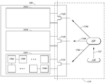
이제 도 1로 돌아가면, 전압을 클리핑하도록 구성된 예시적인 회로를 구비한 PV 모듈이 도시되어 있다. 일부 실시예들에서, PV 모듈(100)과 같은 PV 모듈이, 스트링(102a, 102b, 102c)과 같은 전지 스트링(cell string)으로 지칭되는 태양 전지들의 수 개의 그룹으로 세분화될 수 있다. 전지 스트링은, 예를 들어 스트링(102c) 내에 태양 전지(104a, 104b, …, 104n)에 의해 도시된 바와 같이 10 내지 40개의 개별적인 직렬 연결된 태양 전지들과 같은, 복수의 직렬 연결된 태양 전지들을 포함할 수 있다. 일반적으로, 스트링 내의 태양 전지들의 개수 및 PV 모듈 내의 스트링들의 개수는 스트링과 PV 모듈에 의해 생성되는 전압을 각각 결정한다. 도 1의 예시적인 PV 모듈이 3개의 태양 전지 스트링들을 도시하지만, 다른 실시예들에서 다른 개수의 스트링들이 PV 모듈 내에서 직렬로 결합될 수 있다.Turning now to FIG. 1, there is shown a PV module with exemplary circuitry configured to clip a voltage. In some embodiments, a PV module, such as
일 실시예에서, 본 명세서에서 전압 클리핑 또는 과전압 회로로서 또한 지칭되는 회로(110)는 과전압 조건에서의 동작에 대해 (또는 이후에 기술되는 바와 같이, 역방향 바이어스, 열점 상태에서의 동작에 대해) 하나 이상의 전지, 스트링, 및/또는 모듈을 보호하도록 구성될 수 있다. 회로(110)는 각자의 전지 스트링의 출력이 예를 들어 하나 이상의 스위치의 구성에 기초하여 PV 모듈의 출력에 포함될 수 있거나 또는 그로부터 제외될 수 있도록 각각의 전지 스트링을 가로질러 제공된 병렬 전류 경로를 포함할 수 있다. 병렬 전류 경로는 PV 모듈의 생성된 전압을 낮출 수 있는 전지 스트링의 출력에 대한 총 임피던스를 낮추도록 구성될 수 있다. 다른 실시예들에서, 유사한 효과를 달성하기 위해 전체 PV 모듈, 복수의 전지들, 복수의 스트링들, 또는 복수의 모듈들을 가로질러 병렬 전류 경로가 제공될 수 있다.In one embodiment, a
일부 실시예들에서, 회로(110)가 병렬 경로의 다양한 순열들 사이에서 절환하도록 구성될 수 있다. 예를 들어, 회로(110)는 PV 모듈의 출력 전압이 복수의 태양 전지들(예컨대, 각각의 스트링) 전체로부터의 전압을 포함하는 제1 상태와 태양 전지들 중 적어도 일부가 PV 모듈의 출력 전압에의 전압의 제공으로부터 바이패스되는 하나 이상의 다른 상태에서 작동하고 이러한 상태들 사이에서 절환하도록 구성될 수 있다. 예를 들어, 회로는 PV 모듈이 그의 태양 전지들 전부로부터 출력하도록 구성된 상태와, PV 모듈이 그의 태양 전지들 중 2/3으로부터 출력하는 상태와, PV 모듈이 그의 태양 전지들 중 1/3로부터 출력하는 다른 상태에서 동작하며 이러한 상태들 사이에서 절환하도록 구성될 수 있다. 다른 예로서, 회로는 PV 모듈이 그의 태양 전지들 전부로부터 출력하는 하나의 상태와 PV 모듈이 그의 태양 전지들 전부보다 더 적은 태양 전지들(예컨대, 대략 그의 태양 전지들의 75%)로부터 출력하도록 구성된 다른 상태에서 동작하며 이러한 상태들 사이에서 절환하도록 구성될 수 있다.In some embodiments,
일 실시예에서, 회로(110)의 하나 이상의 스위치가 인에이블된 상태에서, 병렬 전류 경로가 모든 또는 거의 모든 전지 스트링의 전류를 취하여 스트링의 전압을 감소 또는 최소화하게 할 수 있으며, 이는 PV 모듈의 전압 출력이 그의 VOC 출력의 대략 75%까지 강하하게 할 수 있다. DC-DC 변환기와 달리, 병렬 전류 경로는 커패시터 또는 자기 요소(magnetic element)와 같은 에너지 저장 요소를 필요로 하지 않음으로써, 전기적 요건을 용이하게 한다. 부가적으로, 절환 전원을 사용함이 없이 모듈 전압을 제한하는 것은 최소의 전자기 간섭(electromagnetic interference, EMI)을 생성한다는 이점을 제공할 수 있으며, 이는 설계 요건을 단순화하고 통신 장비와 같은 다른 전자 장비와의 간섭을 최소화할 수 있다. 더욱이, 또한 DC-DC 변환기와 달리, 동일한 IV 곡선이 사용되지만 PV 모듈이 효율적으로 더 작게 제조된다.In one embodiment, with one or more switches of the
일 실시예에서, 병렬 전류 경로는 계전기(relay), 전계 효과 트랜지스터(field effect transistor, FET), 양극성 접합 트랜지스터(bipolar junction transistor, BJT), 절연 게이트 양극성 트랜지스터(insulated-gate bipolar transistor, IGBT), 또는 다른 절환 메커니즘과 같은 스위치 또는 스위치들을 사용하여 구현될 수 있다. 따라서, 하나 이상의 태양 전지가, 병렬 전류 경로를 가능하게 하도록 하나 이상의 태양 전지를 가로질러 스위치(예컨대, 스위치(112a, 112b 및/또는 112c))를 폐쇄시킴으로써, 단락될 수 있다(예컨대, 바이패스된다). 스위치들은 도 1에서 FET(112a, 112b, 112c)로서 도시되어 있다. 도 1의 예에서 도시된 바와 같이, 각각의 전지 스트링이 각자의 스위치와 연관될 수 있다. 다른 실시예들에서, 도 3에 도시된 바와 같이 이것이 반드시 그러한 것은 아니다.In one embodiment, the parallel current path includes a relay, a field effect transistor (FET), a bipolar junction transistor (BJT), an insulated-gate bipolar transistor (IGBT) Or other switching mechanism, for example. Thus, one or more solar cells can be short-circuited (e.g., by bypassing) a switch (e.g., switches 112a, 112b, and / or 112c) across one or more solar cells to enable a parallel current path do). The switches are shown as FETs 112a, 112b, and 112c in FIG. As shown in the example of Figure 1, each battery string may be associated with a respective switch. In other embodiments, this is not necessarily so, as shown in FIG.
일 실시예에서, 회로(110)는 드라이버(120)에 신호를 제공하도록 구성된 아날로그 또는 디지털 제어기(130)를 포함할 수 있으며, 드라이버는 전지 스트링을 단락시킴으로써 그 전지 스트링으로부터의 전압 기여를 대략 0 볼트까지 감소시키기 위해, 신호(134a, 134b, 134c)들에 의해 나타낸 바와 같이, 스위치(들)를 온 상태로 하도록(예를 들어, 인에이블, 연결, 폐쇄, 활성화하도록) 구성될 수 있다. 본 명세서에 사용되는 바와 같이, 드라이버(120)는 스위치가 온 또는 오프 상태가 되게 명령하는 제어기(130) 출력을 레벨 이동하도록 구성된 회로(예컨대, 하나 이상의 트랜지스터)일 수 있다. 절환이 전체 전지 스트링 상에서 수행되는 것으로 기술되었지만, 일부 실시예들에서, 절환은 전지 레벨에서, 모듈 레벨에서, 또는 전지 레벨, 스트링 레벨 및/또는 모듈 레벨의 일부 조합으로 수행될 수 있다.In one embodiment, the
다양한 실시예들에서, 제어기(예컨대, 아날로그 또는 디지털)가 하드웨어, 펌웨어, 소프트웨어, 또는 이들의 일부 조합을 사용하여 구현될 수 있다. 일 실시예에서, 제어기는 병렬 경로가 안전하게 오프 상태로 될(예컨대, 개방, 디스에이블, 연결해제, 비활성화될) 수 있다고 결정하도록 그리고 병렬 경로가 하나 이상의 전지를 단락시켜 그러한 하나 이상의 전지(및 그 결과 모듈 및 시스템)의 출력 전압을 클리핑하기 위해 연결되어야 할 때를 결정하도록 구성될 수 있다. 일부 실시예들에서, 제어기는 아래에서 더 상세하게 기술되는 바와 같이 어떤 전지 스트링을 클리핑할 것인지를 선택하도록 구성될 수 있다.In various embodiments, a controller (e.g., analog or digital) may be implemented using hardware, firmware, software, or some combination thereof. In one embodiment, the controller is configured to determine that the parallel path can be safely turned off (e.g., open, disable, disconnect, deactivate) and the parallel path shorts one or more cells, The resulting module and the system) to be clipped. In some embodiments, the controller may be configured to select which battery string to clip as described in more detail below.
일 실시예에서, 병렬 경로를 연결 또는 연결해제하기 위해 스위치를 온 또는 오프 상태로 할지 여부에 대한 결정이 전압 및/또는 전류 측정치에 기초할 수 있다. 예로서, 전압 감지 메커니즘(도시되지 않음)이 전지 스트링에 결합되어 그 스트링의 전압 기여를 측정할 수 있다. 그 전압에 기초하여, 제어기는 스트링의 전압을 클리핑할지 여부를 결정할 수 있다. 예를 들어, 측정된 전압이 임계 값(예컨대, 스트링 또는 모듈의 최대 전력점 전압(Vmpp))을 초과한다면, 전지 스트링들 중 하나가 바이패스될 수 있다.In one embodiment, the determination of whether to turn the switch on or off to connect or disconnect the parallel path may be based on voltage and / or current measurements. As an example, a voltage sensing mechanism (not shown) may be coupled to the battery string to measure the voltage contribution of the string. Based on that voltage, the controller can determine whether to clump the voltage of the string. For example, if the measured voltage exceeds a threshold (e.g., string or module maximum power point voltage (V mpp )), one of the battery strings may be bypassed.
다른 예로서, 별개의 전압 감지 메커니즘이 모듈 내의 각각의 각자 스트링에 결합될 수 있다. 측정된 전압들의 합이 모듈에 대한 임계 값을 초과한다면, 전지 스트링들 중 하나 이상이 병렬 경로를 인에이블시킴으로써 바이패스될 수 있다. 어느 예에서든, 전압을 임계 전압 아래의 레벨로 감소시키도록 하나 이상의 스트링을 바이패스함으로써, 임계 값이 초과되지 않는 것을 보장하면서 전체 모듈로부터 수확되는 전력량이 최대화될 수 있다. 부가적으로, 아래에서 더 상세하게 기술되는 바와 같이, 열점이 검출되면(예컨대, 측정된 전압이 0V 아래로 하강하면), 측정이 이루어진 전지 스트링은 그 스트링에 대한 병렬 경로를 인에이블시킴으로써 바이패스될 수 있다.As another example, separate voltage sensing mechanisms can be coupled to each self string in the module. If the sum of the measured voltages exceeds the threshold for the module, one or more of the battery strings may be bypassed by enabling the parallel path. In either example, by bypassing one or more strings to reduce the voltage to a level below the threshold voltage, the amount of power harvested from the entire module can be maximized while ensuring that the threshold is not exceeded. Additionally, as described in more detail below, when a hot spot is detected (e.g., the measured voltage falls below 0V), the measured battery string is bypassed by enabling a parallel path to that string .
일부 실시예들에서, 스위치가 연결되고 병렬 경로가 인에이블된 후에, 제어기는 개방 회로 전압 측정에 더 이상 접근할 수 없다. 따라서, 제어기는 스위치가 안전하게 연결해제되고 정상 동작으로 복귀할 수 있는지 여부를 더 이상 결정가능하지 않을 수 있다. 스위치가 안전하게 연결해제될 수 있는 때를 결정하기 위해 다양한 기술들이 구현될 수 있다. 예를 들어, 스위치의 연결해제는 타이머에 기초하거나, 전류 측정에 기초하거나, 한 번에 스트링들 중 2개의 측정에 기초할 수 있다. 스위치(들)를 언제 연결해제할지를 결정하는 다양한 기술들 및 예들이 도 10에서 아래에서 더 상세하게 기술된다.In some embodiments, after the switch is connected and the parallel path is enabled, the controller is no longer able to access the open circuit voltage measurement. Thus, the controller may not be able to further determine whether the switch can be safely disconnected and return to normal operation. Various techniques may be implemented to determine when the switch can be safely disconnected. For example, the disconnection of a switch may be based on a timer, based on current measurements, or based on two measurements of strings at a time. Various techniques and examples for determining when to disconnect the switch (s) are described in more detail below in Fig.
다양한 실시예들에서, 각각의 PV 모듈이 (예컨대, 접속함 내의, 라미네이트 내의) 모듈의 부분으로서 각자의 로컬 제어기를 포함할 수 있거나, 하나 이상의 모듈을 제어하도록 외부 제어기가 제공될 수 있다. 일 실시예에서, 스위치의 개방 또는 폐쇄는 분산된 회로(예컨대, 전압 클리핑 장치들)로의 유선 또는 무선(예컨대, 지그비(Zigbee), 메시 네트워크, WiFi, 블루투스 등) 통신을 통해 중앙 제어기에 의해 제어될 수 있다.In various embodiments, each PV module may include its own local controller as part of the module (e.g., in a laminate, in a junction box), or an external controller may be provided to control one or more modules. In one embodiment, the opening or closing of the switch may be controlled by a central controller via wired or wireless (e.g., Zigbee, mesh network, WiFi, Bluetooth, etc.) communication to distributed circuitry (e.g., voltage clipping devices) .
일부 실시예들에서, 로컬 및 외부 제어기들의 일부 조합이 병렬 경로들을 연결 및 연결해제하는 데 사용될 수 있다. 예를 들어, 스위치를 개방 또는 폐쇄할지 여부의 결정은 중앙 제어기에 의해 제공되는 하나 이상의 파라미터(예컨대, 임계 전압)에 기초하여 로컬 제어기에 의해 수행될 수 있다.In some embodiments, some combination of local and external controllers may be used to connect and disconnect parallel paths. For example, the determination of whether to open or close the switch may be performed by the local controller based on one or more parameters (e.g., threshold voltage) provided by the central controller.
일 실시예에서, 집합적 시스템 전압이 시스템 임계 전압의 아래에 있도록 제어기들이 서로 조정할 수 있다. 예를 들어, 각각의 모듈에 있는 로컬 제어기들이 조정을 위해 서로 통신할 수 있거나, 중앙 제어기가 어떤 스위치들이 개방되어야 하고 어떤 스위치가 폐쇄되어야 하는지에 대한 표시를 제공하도록 각자의 로컬 제어기들과 통신할 수 있다. 따라서, 시스템 레벨에서 전압 클리핑을 조정함으로써, 단락되는 스트링들의 총 개수가 최소화되어 총 시스템을 그의 전압 제한 내에 유지할 수 있다. 그러한 제어 기술은, 다른 모듈들과 독립적으로 고려된다면 다른 방식으로 클리핑될 수 있는 일부 모듈들로부터 모듈 전압을 클리핑하지 않음으로써 시스템에 의해 생성되는 전력을 불필요하게 제한하는 것을 억제하도록 도울 수 있다. 시스템 레벨 조정이 인버터, 접속함 등과 같은 일부 하류측 하드웨어에 연결된 PV 모듈들의 시스템을 지칭할 수 있음에 주목한다. 시스템 레벨 조정은 예를 들어 PV 전력 장치에 있는 모든 PV 모듈들에 대한 조정일 필요가 없다. 대신, 시스템 레벨 조정은 그러한 PV 모듈들의 하위세트(subset)에 대한 조정일 수 있다.In one embodiment, the controllers can coordinate with each other such that the aggregate system voltage is below the system threshold voltage. For example, local controllers in each module may communicate with each other for coordination, or the central controller may communicate with its local controllers to provide an indication of which switches should be open and which switches should be closed . Thus, by adjusting the voltage clipping at the system level, the total number of shorted strings can be minimized to keep the total system within its voltage limit. Such a control technique may help to suppress unnecessarily limiting the power generated by the system by not clipping the module voltage from some modules that may be clipped in other ways if considered independently of other modules. Note that system level adjustments may refer to systems of PV modules connected to some downstream hardware, such as inverters, junction boxes, and the like. The system level adjustment need not be an adjustment for all the PV modules in the PV power device, for example. Instead, the system level adjustment may be an adjustment to a subset of such PV modules.
다양한 실시예들에서, 태양 에너지 시스템 내의 전압 제한 회로는, 공통적인 동작 상태 동안에, 전체가 아닌 일부 전압 제한 회로들이 활성화되도록 상이한 레벨들에서 각자의 태양 전지들의 전압들을 제한하도록 구성될 수 있다.In various embodiments, the voltage limiting circuit in the solar energy system may be configured to limit the voltages of the respective solar cells at different levels so that some, but not all, voltage limiting circuits are activated during a common operating state.
일부 실시예들에서, 스트링들에 의해 제공되는 전압 및 전류가 PV 모듈 외부의 부하에 결합될 수 있도록, 하나 이상의 전지 스트링이 접속함을 통해 접근될 수 있다. 일 실시예에서, 회로(110)는 접속함 내에 내장될 수 있다. 일 실시예에서, 연관된 전지들이 역방향 바이어스에서 동작하고 있다면, 접속함은 전기를 전도시킬 수 있는 복수의 바이패스 다이오드들(예컨대, 스트링당 하나의 바이패스 다이오드)을 포함할 수 있다. 본 명세서에 기술된 바와 같이, 개시된 구조 및 기술들이 바이패스 다이오드들과 함께 또는 그 대신 사용될 수 있으며 역방향 바이어스 보호를 제공한다.In some embodiments, one or more battery strings can be accessed through the junction box such that the voltage and current provided by the strings can be coupled to a load external to the PV module. In one embodiment, the
일부 실시예들에서, 회로(110)가 접속함 내에 위치되는 대신에, 과전압 보호 장치의 하나 이상의 구성요소가 PV 모듈의 봉지부(encapsulation) 내부, 또는 PV 모듈 외부와 같은 다른 위치들에 위치될 수 있다.In some embodiments, instead of being located within the junction box, the
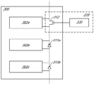
도 2는 전압을 클리핑하도록 구성된 회로의 다른 예를 도시한다. 설명과 예시의 용이성을 위해, 실제 PV 모듈 및 개별 태양 전지들이 도 2에 도시되어 있지 않다. 또한, 도 1의 다양한 요소들(예컨대, 병렬 경로, 스위치, 제어기 등)의 설명이 본 명세서의 다른 도면들에 대해서도 동일하게 적용되지만, 설명의 간결성을 위해서 반복되지 않을 수 있다.Figure 2 shows another example of a circuit configured to clip a voltage. For ease of explanation and illustration, actual PV modules and individual solar cells are not shown in FIG. In addition, the description of the various elements (e.g., parallel paths, switches, controllers, etc.) of FIG. 1 applies equally to the other figures of this specification, but may not be repeated for clarity of explanation.
도 2의 예시적인 회로(110)의 하나의 차이점은 각각의 스위치에 대한 개별 드라이버의 사용이다. 도시된 바와 같이, 제어기(130)는 별개의 드라이버들, 즉 드라이버(120a, 120b, 120c)들에 신호들을 제공하도록 구성된다. 이어서, 드라이버(120a, 120b, 120c)들 각각은 제어기(130)로부터의 신호에 응답하여 그들 각자의 스위치 온 또는 오프를 명령하도록 구성될 수 있다.One difference of the
개시된 회로 및 병렬 전류 경로가 스트링 또는 모듈 내의 모든 전지들에 영향을 미칠 필요가 없음에 주목한다. 예를 들어, 병렬 전류 경로에 의해 제공되는 전압 클리핑 능력은, 도 3에 도시된 바와 같이 스트링, 모듈, 또는 태양 에너지 시스템 내의 전지들의 하위세트 상에서만 사용될 수 있다. 도 3에 도시된 바와 같이, 회로(310)는 PV 모듈(300)의 모든 태양 전지들이 모듈의 출력에 전압을 제공하도록 구성된 최대 전력 상태와 스트링(302a)이 모듈의 출력에의 그의 전압의 제공으로부터 클리핑되는 상태 사이에서 PV 모듈(300)을 절환시키도록 구성된다. 그러한 실시예에서, 제어기(330)는 별개의 드라이버의 사용 없이 스위치(312)를 직접 인에이블 또는 디스에이블할 수 있다. 도시된 예에서, 스트링(302b, 302c)들의 전압을 클리핑하기 위한 별개의 스위치들이 이들 스트링에 대해 존재하지 않는다. 대신에, 두 가지 주요 상태들, 즉 3개의 스트링들 모두로부터의 최대 전압이 출력되는 상태 및 스트링들 중 2개로부터의 전압이 출력되는 다른 상태가 존재한다. 스트링(302b, 302c)들에 대한 열점 보호가 다이오드(315a, 315b)들을 각각 바이패스함으로써 제공될 수 있다. 바이패스 다이오드는 또한 스트링(302a)에 대한 열점 보호를 위해 사용될 수 있거나, 회로(312)가 그러한 보호를 제공할 수 있다.Note that the disclosed circuit and parallel current path need not affect all the cells in the string or module. For example, the voltage clipping capability provided by the parallel current path can only be used on a subset of cells in a string, module, or solar energy system, as shown in FIG. As shown in Figure 3, the
도 3의 실제적인 예로서, 일 실시예에서, 스위치는 모듈 내의 태양 전지들의 대략 25%를 구성하는 태양 전지 스트링과 연관될 수 있다. 그 스트링은, 그 스트링(또는 전체 모듈)의 전압이 임계 전압을 초과한다면 단락될 수 있다. 스트링이 단락되면, 태양 전지들의 대략 75%가 그들의 전압을 모듈의 출력에 제공한다. 일 실시예에서, 임계 전압은 다른 예들 중에서도 대략 PV 모듈의 Vmpp 또는 스트링의 Vmpp일 수 있다. 예를 들어, 모듈의 Vmpp가 60V이고 임계 전압이 62V라면, 측정된 전압이 62V를 만족하거나 이를 초과하는 경우에 스위치가 폐쇄되어 태양 전지들의 단락된 스트링이 모듈의 출력 전압에 기여하지 않게 할 수 있다. 따라서, 모듈이 62V 위에서 동작하지 않아 모듈이 VOC에 도달하지 않고 시스템(예컨대, BOS 구성요소들)이 VOC를 수용하도록 크기 설정될 필요가 없게 하는 것이 보장될 수 있다.As a practical example of Figure 3, in one embodiment, the switch may be associated with a solar cell string that makes up about 25% of the solar cells in the module. The string may be shorted if the voltage of the string (or the entire module) exceeds the threshold voltage. If the strings are shorted, approximately 75% of the solar cells provide their voltage to the output of the module. In one embodiment, the threshold voltage may be V mpp of a PV module or V mpp of a string, among other examples. For example, if the module's V mpp is 60V and the threshold voltage is 62V, then the switch is closed if the measured voltage meets or exceeds 62V so that the shorted string of solar cells does not contribute to the output voltage of the module . Thus, it can be ensured that the module does not operate above 62V, so that the module does not reach V OC and the system (e.g., BOS components) need not be sized to accommodate V OC .
DC-DC 변환기 기반 시스템에서와 같이 IV 곡선을 수정하는 대신에, 개시된 시스템은 별개 IV 곡선들 사이에서 효과적으로 동작한다. DC-DC 변환기 시스템에 대해 전압을 클리핑하는 병렬 경로 절환 메커니즘의 하나의 이점은, DC-DC 변환기 시스템에 있어서 각각의 모듈에 대해 수정된 동작 전류가 동일해야 한다는 것이다. 그러한 제한은 개시된 시스템에 대해 존재하지 않는다.Instead of modifying the IV curve as in a DC-DC converter based system, the disclosed system works effectively between distinct IV curves. One advantage of the parallel path switching mechanism for clipping the voltage to the DC-DC converter system is that the modified operating current for each module in the DC-DC converter system must be the same. Such restrictions do not exist for the disclosed system.
개시된 구조들 및 기술들은, 시스템이 차선적으로 수행하고 에너지 수확을 최대화하는 것이 중요하지는 않은 과전압 경우에서, DC-DC 전력 최적화기의 비용 및 효율의 불이익 없이 전압을 제한하는 능력을 제공할 수 있다. 출력 전압이 항상 DC-DC 최적화기를 통과하고 필요하지 않을 때에도 손실 전압의 측면에서 적어도 일부 효율성 손실을 겪는 DC-DC 최적화기 기반 시스템들과는 대조적으로, 개시된 과전압 보호는, 전압이 임계치를 초과하지만 전압이 정상 동작 조건 하에서 불필요하게 손실되지 않도록 정상 동작 조건 하에 있지 않는 것에 응답하여 이용될 수 있다.The disclosed structures and techniques may provide the ability to limit the voltage without penalty of cost and efficiency of the DC-DC power optimizer in overvoltage cases where the system performs sub-optimal and maximizes energy harvest is not critical . In contrast to DC-DC optimizer based systems where the output voltage always passes through the DC-DC optimizer and experiences at least some loss of efficiency in terms of lost voltage even when not needed, the disclosed overvoltage protection is based on the fact that the voltage exceeds the threshold, May be used in response to being not under normal operating conditions so as not to be unnecessarily lost under normal operating conditions.
일부 실시예들에서, 경로를 제공하고 시스템 설계 제한을 만족시키기 위해 출력 전압을 제한하도록 태양 전지들과 병렬로 배치되는 스위치들은 시스템의 안전 정지(safety shutdown)를 위해서 또한 사용될 수 있다. 전지 스트링들의 임피던스를 상당히 감소시키기 위해 또는 전지 스트링들을 완전히 단락시키기 위해 스위치들을 사용함으로써, 태양 시스템의 출력 전압 및 전력이 급격하게 감소될 수 있다. 안전 정지는, 예를 들어 화재 동안에, 아크 결함(arc fault)이 검출될 때, 시스템의 유지보수 동안에, 또는 다른 안전 이유로 인해 사용될 수 있다. 일 실시예에서, 제어기는 디폴트로, 하나 이상의 전지 스트링이 효과적으로 단락되는 위치로 될 수 있다.In some embodiments, switches disposed in parallel with the solar cells to provide a path and to limit the output voltage to meet system design limitations may also be used for system safety shutdown. By using switches to significantly reduce the impedance of the battery strings or to short the battery strings completely, the output voltage and power of the solar system can be drastically reduced. Safe shutdown can be used, for example during a fire, when an arc fault is detected, during maintenance of the system, or for other safety reasons. In one embodiment, the controller can, by default, be in a position where one or more battery strings are effectively short-circuited.
다양한 실시예들에서, 유사한 구조들 및 기술들이 태양 모듈들에서의 열점 가열, 역방향 바이어스를 해결하기 위해 사용될 수 있다. 위에 언급된 바와 같이, 예를 들어 그늘짐 또는 결함으로 인해 태양 전지가 정상 작동하지 않는 경우에, 태양 전지는 주변 전지들보다 더 낮은 전류로 동작할 수 있으며, 이는 전지가 역방향 바이어스에 놓이게 할 수 있다. 역방향 바이어스는 상당한 전력 손실 및 전지 내의 가열을 야기하여, 전지 또는 주변 태양 모듈 구조물을 손상시킬 수 있다. 유사한 효과가 태양 모듈 내부에서의 접속 또는 땜납 연결의 실패로 인해 발생할 수 있음에 주목한다. 상황에 있어서, 일부 시스템이 열점 가열을 다루기 위해서 바이패스 다이오드를 이용한다. 예를 들어, 전지 스트링이 다른 전지 스트링들의 최대 전력점 전류(Impp)에 도달하기에 충분한 전류를 생성할 수 없고, 다이오드를 가로지른 전압 강하가 전지 스트링 내의 태양 전지들의 역방향 바이어스 전압보다 작다면, 바이패스 다이오드가 순방향 바이어스되어 전지 스트링을 단락시킨다. 그러나, 그러한 다이오드와 연관된 전압 강하(예컨대, 대략 0.3V 내지 0.5V)는 열 소산(heat dissipation)을 통한 전력 손실을 야기한다. 열 소산은 태양 모듈 효율성이 떨어지게 할 수 있으며, 심지어 다이오드를 파괴시킬 수 있는 과열을 초래할 수 있다. 다이오드가 단락에 실패하면, PV 모듈의 전력의 상당한 부분이 영구적으로 손실될 수 있다. 다이오드가 개방에 실패하면, 연관된 전지 스트링이 태양 전지 열점에 대해 취약한 채로 남게 되며, 이는 잠재적으로 PV 모듈을 파괴시킬 수 있다.In various embodiments, similar structures and techniques may be used to solve the hot spot heating, reverse bias in solar modules. As noted above, for example, when a solar cell is not operating normally due to shading or defects, the solar cell may operate at a lower current than peripheral cells, which may cause the cell to be placed in a reverse bias have. Reverse bias can cause significant power loss and heating within the cell, damaging the battery or surrounding solar module structure. Note that a similar effect may occur due to a connection inside the solar module or failure of the solder connection. In some situations, some systems use bypass diodes to handle hot spot heating. For example, if the battery string can not generate enough current to reach the maximum power point current (I mpp ) of other battery strings and the voltage drop across the diode is less than the reverse bias voltage of the solar cells in the battery string , The bypass diode is forward biased to short-circuit the battery string. However, the voltage drop associated with such a diode (e.g., approximately 0.3V to 0.5V) causes power dissipation through heat dissipation. Heat dissipation can degrade the efficiency of the solar module and can even lead to overheating, which can destroy the diode. If the diode fails a short, a significant portion of the power of the PV module may be permanently lost. If the diode fails to open, the associated battery string remains vulnerable to solar cell hot spots, which can potentially destroy the PV module.
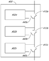
열점으로 인한 바이패스 다이오드의 사용의 제한들 중 일부를 해소하기 위해, 개시된 회로, 병렬 전도성 경로 및 기술들이 열점을 억제하기 위해 사용될 수 있다. 도 4는 하나의 그러한 예를 도시한다.To overcome some of the limitations of using bypass diodes due to hot spots, the disclosed circuit, parallel conductive path and techniques may be used to suppress hot spots. Figure 4 shows one such example.
일 실시예에서, 열점 가열을 억제하기 위하여, 전력 손실을 억제하고 가열을 감소시키도록 역방향 바이어스 상태를 방지하기 위해 전지의 전류가 제한될 수 있다. 회로는, 도 4의 차단 스위치(440a, 440b, 440c)에 의해 도시된 바와 같이, 각각 전지 스트링(들)(402a, 402b, 402c)을 통한 전류를 제한하도록 차단될 수 있다. 도 4는 전지 스트링 레벨에서의 열점 상태의 완화를 나타내지만, 예를 들어 전체 PV 모듈을 가로지른, 전지들의 다른 길이들에 대해 유사한 보호 메커니즘이 구현될 수 있다.In one embodiment, to inhibit hot spot heating, the current in the battery may be limited to prevent reverse bias conditions to suppress power loss and reduce heating. The circuit may be shut off to limit the current through the battery string (s) 402a, 402b, 402c, respectively, as shown by the
그러나, 회로를 완전히 차단하는 것은 주변의 태양 전지 및 모듈에서의 수용가능하지 않은 전력 손실로 이어질 수 있다. 전압 클리핑 목적으로 병렬 경로를 제공하는 바이패스 스위치(412a, 412b, 412c)들은, 열점을 방지하도록 회로로부터 제거된 태양 전지들을 바이패스하기 위해, 잘 수행하는 태양 전지들로부터의 전류에 대한 경로를 제공하는 데 사용될 수 있다. 도 4에 도시된 바와 같이, 전지 스트링에 대한 열점 상태는 병렬 전도 경로를 단락시키고 전지 스트링을 통한 회로를 차단함으로써 완화될 수 있다. 또한, 일단 (예컨대, 전류 및/또는 전압 측정 또는 다른 센서로부터) 열점이 검출되면, 제어기는 유지 보수 방문까지 또는 다른 진단 검사가 문제를 고치거나 열점 상태가 더 이상 존재하지 않는다고 결정할 때까지, 안전한(예컨대, 제한된 전류) 위치에서 열점을 포함하는 전지 스트링을 배치하도록 차단 스위치(440a, 440b, 및/또는 440c)들 및/또는 바이패스 스위치(412a, 412b, 및/또는 412c)들을 구성할 수 있다.However, shutting off the circuit completely can lead to unacceptable power loss in the surrounding solar cells and modules.
또한, 전류가 임계 레벨을 초과할 때 전류를 클리핑하기 위한 유사한 상황이 존재함에 주목한다. 예를 들어, 일 실시예에서, 가변 임피던스를 갖는 경로가 주요 전류 경로에 대해 병렬로 배치될 수 있다. 임피던스는 아날로그 또는 디지털 제어 신호를 통해 제어될 수 있다. 병렬 경로의 임피던스를 감소시키는 것은 주요 경로로부터의 전류를 방향전환시켜 주요 경로를 통한 전류를 감소시킨다. 병렬 경로의 임피던스를 증가시키는 것은 전류가 주요 경로를 선호하게 하여, 주요 경로를 통한 전류를 증가시킨다.It is also noted that there is a similar situation for clipping current when the current exceeds the threshold level. For example, in one embodiment, paths with variable impedance may be placed in parallel with respect to the main current path. Impedance can be controlled via analog or digital control signals. Reducing the impedance of the parallel path redirects the current from the main path to reduce the current through the main path. Increasing the impedance of the parallel path causes the current to prefer the main path, increasing the current through the main path.
예를 들어 열점을 다루기 위해 전지 스트링을 바이패스하도록 스위치를 사용하는 것은, 바이패스 다이오드를 사용하는 시스템 내의 약 0.5 V와 비교하여 50 ㎷ 이하로 전압 강하를 감소시킬 수 있다. 또한, 개시된 병렬 경로 구성을 사용함으로써, 바이패스 다이오드들이 전지 스트링들에 걸쳐 계전기, FET, BJT 또는 IGBT와 같은 스위치로 대체될 수 있거나, 바이패스 다이오드들이 개시된 회로에 대한 백업으로서 사용될 수 있다. 스위치는 본 명세서에 기술된 바와 같이 스트링을 단락시키고 그 스트링을 바이패스하기 위해서 온 상태로 될 수 있다.For example, using a switch to bypass a battery string to handle a hot spot can reduce the voltage drop to less than 50 비교 compared to about 0.5 V in a system that uses a bypass diode. Also, by using the disclosed parallel path configuration, bypass diodes can be replaced with switches such as relays, FETs, BJTs or IGBTs across the battery strings, or bypass diodes can be used as a backup to the disclosed circuit. The switch may be turned on to short the string and bypass the string as described herein.
일 실시예에서, 종래의 다이오드(예컨대, 규소, 쇼트키(Schottky))가 바이패스 스위치에 대한 백업으로서 작동하도록 바이패스 스위치와 병렬로 배열될 수 있다. 이러한 기능은 또한 적합한 특징들을 갖는 일부 스위치들(예컨대, FET)의 바디 다이오드(body diode)에 의해 일부 구현들에서 만족될 수 있다.In one embodiment, a conventional diode (e.g., silicon, Schottky) may be arranged in parallel with the bypass switch to operate as a backup to the bypass switch. This function may also be satisfied in some implementations by the body diode of some switches (e.g., FETs) with suitable features.
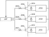
아날로그 또는 디지털 제어기는 스위치를 오프 상태로 하는 것이 안전한 상태, 그리고 전지 스트링이 스위치를 온 상태로 함으로써 바이패스되어야 할 때를 결정할 수 있다. 이 상태는 전압 및/또는 전류 측정에 의해 결정될 수 있다. 도 5는 그러한 바이패스 제어 메커니즘 및 회로의 예를 도시하는데, 이에 의해 제어기(530)는 스위치로서 기능하는 FET의 바디 다이오드를 가로지른 전압 강하를 측정하도록 각각의 전지 스트링 상의 전압 감지부(511a, 511b, 511c)를 사용한다. 바디 다이오드를 가로지른 전압이 특정 범위 내에 있다면, 바이패스 상태가 존재할 수 있다. 제어기(530)는 이어서 바이패스 FET(505a, 505b, 또는 505c)와 같은 바이패스 FET를 온 상태로 하기 위한 신호를 생성하여, FET가 전압 강하를 감소시키기 위해 전류의 대부분을 전도시킴으로써 바이패스 동안에 소산되는 전력을 감소시킬 수 있다. 일 실시예에서, FET의 바디 다이오드를 대신하여 별개의 다이오드가 사용될 수 있다.The analog or digital controller can determine when it is safe to turn the switch off and when the battery string should be bypassed by turning the switch on. This state can be determined by voltage and / or current measurements. 5 shows an example of such a bypass control mechanism and circuit whereby the
일부 실시예들에서, 제어 신호의 손실이 일어난다면 시스템이 안전한 상태에 놓일 수 있도록(예컨대, 제어 회로로의 전력이 손실되는 경우에 병렬 스위치들을 "온" 상태로 놓음) 전압 클리핑 또는 열점 방지 회로에 대해 결함-안전 메커니즘(fail-safe mechanism)이 제공될 수 있다. 일부 구현예들에서, 스위치들이 디지털 제어기(예컨대, 마이크로컨트롤러) 또는 아날로그 제어기에 의해 구동(예컨대, 활성화, 단락, 연결)되기 때문에, 스위치들은 구동원이 전력을 손실한다면 오프(개방) 상태로 유지될 수 있다. 구동원이 전력을 손실한 경우에, 스위치들은 PV 모듈의 전압을 제한하고 모듈을 보호하기 위해 온 상태로 되도록 구성될 수 있다.In some embodiments, if a loss of control signal occurs, the system may be placed in a safe state (e.g., putting the parallel switches in an "on" state if power to the control circuit is lost) A fail-safe mechanism may be provided for the < / RTI > In some implementations, since the switches are driven (e.g., activated, shorted, connected) by a digital controller (e.g., a microcontroller) or an analog controller, the switches remain in an off (open) state if the drive source loses power . In the event that the drive source has lost power, the switches may be configured to limit the voltage of the PV module and turn it on to protect the module.
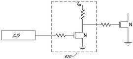
도 6은 전압 클리핑 회로 내의 스위치가 N-채널 향상-모드 FET(바이패스 FET) 내의 스위치인 예를 도시한다. 일 실시예에서, FET는 통상적으로 마이크로컨트롤러 또는 다른 신호-발생 회로에 의해 직접 제어되는 다른 N FET에 의해 구동될 수 있다. 제어기(630)가 전력을 손실하면, 구동 N FET가 개방된 채로 유지될 것이다. VDD와 구동 N FET의 소스 사이에 결합된 풀업 저항기(pull-up resistor)가 그러한 고장의 경우에 바이패스 FET를 온 상태로 하기 위해 사용될 수 있다. 따라서, 바이패스 N FET는, 풀업 저항기를 통해 1차 게이트를 하이(high)로 유지하고 정상 동작 동안에 1차 게이트를 로우(low)로 구동하기 위해 2차 구동 N FET를 사용함으로써, 바이패스 N FET의 드라이버가 전력을 손실하는 경우에 단락될 수 있다. 다른 변형들이 또한 존재한다.6 shows an example in which the switch in the voltage clipping circuit is a switch in an N-channel enhancement-mode FET (bypass FET). In one embodiment, the FET may be driven by another N FET, which is typically directly controlled by a microcontroller or other signal-generating circuitry. If the
도 7은 바이패스 FET가 P-채널 공핍-모드 FET인 다른 결함-안전 드라이버 예를 도시한다. 그러한 예에서, 바이패스 FET는 통상적으로 P FET의 동작을 에뮬레이팅(emulating)하는 2개의 N FET들의 네트워크에 의해 구동될 수 있다. 제어기(730)가 전력을 손실한다면, 제1 N FET는 개방된 채로 유지되고, 제1 풀업 저항기는 제2 N FET을 온 상태로 구동한다. 제2 N FET는 P FET를 온 상태로 하도록 바이패스 P FET의 게이트를 로우로 풀링할 수 있다. 따라서, 1차 P FET는, 2차 게이트 전압을 하이로 유지하는 풀업 저항기로 인해 단락된 채로 유지되는 2차 N FET를 통해 1차 게이트를 로우로 유지하고, 정상 동작 동안에 2차 게이트를 로우로 (그리고 그에 따라 1차 게이트를 하이로) 구동하기 위해 3차 N FET를 사용함으로써, 1차 P FET의 드라이버가 전력을 손실하는 경우에 단락된다. 다른 변형들이 또한 존재한다.Figure 7 illustrates another example of a fault-safe driver where the bypass FET is a P-channel depletion-mode FET. In such an example, the bypass FET may be driven by a network of two N FETs, which typically emulate the operation of the PFET. If the
도 8의 좌측 부분에 도시된 바와 같은 일부 실시예들에서, P FET의 공통 단자가 GND이어야 하는 경우, P FET의 게이트는 음의 전압을 생성하지 않고 구동되지 않을 수 있다. 그 문제를 해결하기 위해, N FET의 시스템이 P FET를 에뮬레이팅하기 위해 사용될 수 있고, 도 8의 우측 부분에 도시된 바와 같이 P FET의 소스와 비교하여 음의 전압을 생성한다.In some embodiments as shown in the left part of FIG. 8, if the common terminal of the P FET is to be GND, the gate of the P FET may not be driven without generating a negative voltage. To solve the problem, a system of N FETs may be used to emulate the P FET and generate a negative voltage as compared to the source of the P FET, as shown in the right part of FIG.
일부 실시예들에서, 결함-안전 메커니즘은 과전압이 부하에 도달하는 것을 방지하기 위해 사용될 수 있는 아날로그 또는 디지털 방식의 리던던트(redundant) 제어 시스템을 제공하는 것을 포함할 수 있다. 추가된 보호 층은 전지 스트링과 병렬로 구성된 스위치를 제어하는 제너 다이오드, 또는 전지 스트링을 단락시킬 수 있는 스위치를 제어하고 전압 표시를 측정하거나 수신하는 제2 디지털 제어기의 형태를 취할 수 있다. 도 9는 백업 아날로그 결함-안전 메커니즘의 예를 도시한다. 주 제어 신호(902)가 실패하고 주 제어 FET가 개방된 채로 유지된다면, 유선 OR 구성이 아날로그 백업 신호(904)가 백업 FET를 제어하게 할 수 있다. 이러한 아날로그 제어는 비교기, 연산증폭기(op-amp), 또는 유사한 장치(910)를 통해 측정된 전압(906)을 기준 전압(908)과 비교함으로써 구현된다. 측정된 전압이 기준 전압을 초과하면, 비교기는 백업 FET를 온 상태로 하는 백업 신호(904)를 생성할 수 있으며, 스위치를 효과적으로 연결한다.In some embodiments, the fault-safety mechanism may include providing an analog or digital redundant control system that may be used to prevent overvoltage from reaching the load. The added protection layer may take the form of a zener diode that controls a switch configured in parallel with the battery string, or a second digital controller that controls a switch that can short the battery string and that measures or receives a voltage indication. Figure 9 shows an example of a backup analog fault-safety mechanism. If the
기술된 결함-안전 구조들 및 기술들은 스위치들이 디폴트로 전력 없는 상태에서 "온" 상태로 되는 것을 가정하지만, 다른 실시예들에서, 전력이 제어 회로에 제공되지 않으면 구동 회로가 스위치로 하여금 디폴트로 "오프" 상태가 되게 할 수 있다. 또는, 일부 실시예들에서, 공핍-모드 FET와 같이 자연적으로 디폴트로 "온" 상태가 되는 스위치(들)가 구동 회로 및/또는 풀업/풀다운 저항기의 사용 없이 이용될 수 있다.The described fault-safety architectures and techniques assume that the switches are "on" in a power-free state by default, but in other embodiments, if power is not provided to the control circuit, Quot; off "state. Alternatively, in some embodiments, the switch (s) that are naturally in a "on" state by default, such as a depletion-mode FET, may be used without the use of a driver circuit and / or a pullup / pull down resistor.
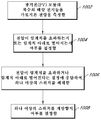
이제 도 10으로 돌아가면, 일부 실시예들에 따라, 전압을 클리핑하기 위한 그리고/또는 달리 PV 모듈 내의 태양 전지들을 바이패스하기 위한 방법을 나타내는 흐름도가 도시되어 있다. 다양한 실시예들에서, 도 10의 방법은 도시된 것보다 추가적인 (또는 더 적은) 블록들을 포함할 수 있다.Turning now to FIG. 10, there is shown a flow diagram illustrating a method for clipping voltage and / or otherwise bypassing solar cells in a PV module, in accordance with some embodiments. In various embodiments, the method of FIG. 10 may include additional (or fewer) blocks than shown.
단계(1002)에서, PV 모듈의 복수의 태양 전지들을 가로질러 전압이 측정될 수 있다. 다양한 실시예들에서, 전압은 전지, 단일 태양 전지 스트링, 다수의 태양 전지 스트링들, PV 모듈 내의 각각의 태양 전지 스트링을 가로질러, 또는 하나 이상의 모듈을 가로질러 측정될 수 있다. 일 실시예에서, 전압은 전압 클리핑 및/또는 바이패스 회로를 내장하는 접속함 내에 위치된 전압 감지 회로를 이용하여 측정될 수 있다. 다른 실시예들에서, 전압은 PV 라미네이트 내에서 측정될 수 있다.In
설명의 많은 부분이 전압의 측정 및 전압의 클리핑에 초점을 맞추고 있지만, 일부 실시예들에서, 단계(1002)에서 전압을 측정하는 것 대신 또는 그에 더하여, 전지, 하나의 전지 스트링, 전지 스트링들, 각각의 전지 스트링을 가로질러, 또는 하나 이상의 모듈을 가로질러 전류가 측정될 수 있다.While much of the description focuses on the measurement of voltage and clipping of voltage, in some embodiments, instead of or in addition to measuring the voltage in
단계(1004)에 예시된 바와 같이, 측정된 전압이 임계치를 초과하는지 또는 임계치 아래로 떨어지는지 여부가 결정될 수 있다. 본 명세서에 기술된 바와 같이, 일 실시예에서, 제어기는 예를 들어 전압 클리핑 응용을 위한 Vmpp 또는 열점 보호 응용을 위한 0 V와 같은 하나 이상의 임계 전압(및/또는 전류)을 가지고 프로그래밍될 수 있거나, 일부 경우들에서 전압 클리핑을 위한 임계 전압 및 열점 보호를 위한 임계 전압과 같은 다수의 임계 전압들을 가지고 프로그래밍될 수 있다. 제어기가 PV 모듈의 각각의 스트링에 대해 별개의 임계 전압들을 가지고 프로그래밍될 수 있음에 주목한다. 예를 들어, 제어기는 3-스트링 PV 모듈 내의 각각의 스트링에 대해 하나씩의 임계 전압인, 3개의 전압 클리핑 임계 전압들을 가지고 프로그래밍될 수 있다. 다양한 실시예들에서, 3개의 전압 클리핑 임계 전압들은 동일하거나 서로 상이할 수 있다.As illustrated in
일 실시예에서, 제어기는 단계(1002)에서 측정된 전압(및/또는 전류)의 표시를 수신할 수 있다. 전압 및 임계 전압의 수신된 표시의 비교에 기초하여, 제어기는 측정된 전압이 클리핑 임계 전압을 초과하는지 또는 열점 임계 전압 아래에 있는지 여부를 결정할 수 있다. 본 명세서에 기술된 바와 같이, 그러한 결정은 다른 예들 중에서도 스트링별 기준(string-by-string basis)으로, 전지별 기준(cell-by-cell basis)으로, 또는 모듈 레벨에서 이루어질 수 있다.In one embodiment, the controller may receive an indication of the measured voltage (and / or current) at
단계(1006)에 예시된 바와 같이, 전압이 임계치를 초과하거나 임계치 아래로 떨어진다는 결정에 응답하여 하나 이상의 스위치가 폐쇄될 수 있다. 하나 이상의 스위치를 폐쇄하는 것은 하나 이상의 연관된 태양 전지로부터의 전압이 PV 모듈의 출력 전압에 제공되는 것을 방지하는 것을 초래할 수 있다.As illustrated in
전압 클리핑 응용에서, 전압이 임계 전압을 초과한다는 결정에 기초하여, 제어기는 하나 이상의 스위치를 직접 인에이블시킬 수 있거나 하나 이상의 스위치를 인에이블시키라는 표시를 드라이버에 제공할 수 있다. 하나 이상의 스위치를 인에이블시킴으로써, 병렬 경로가 인에이블되어, 인에이블된 스위치(들)에 대응하는 태양 전지들이 더 이상 PV 모듈의 출력에 전압을 기여하지 않게 한다.In a voltage clipping application, based on the determination that the voltage exceeds the threshold voltage, the controller can either directly enable one or more switches or provide an indication to the driver to enable one or more switches. By enabling one or more switches, the parallel path is enabled such that the solar cells corresponding to the enabled switch (s) no longer contribute voltage to the output of the PV module.
일 실시예에서, 제어기는 어떤 스트링을 클리핑할 것인지를 결정할 수 있다. 예를 들어, 제어기는 어떤 스트링의 전압을 클리핑할 것인지를 선별적으로 선택함으로써 최대 전력 출력을 최적화할 수 있다. 모듈이 60 V의 전압 임계치를 갖고 스트링 1이 30 V를 기여하며, 스트링 2가 25 V를 기여하고, 스트링 3이 20 V를 기여한다면, 제어기는 스트링 3의 전압을 클리핑하도록 결정하여, 클리핑되지 않은 스트링들로부터의 총 전압이 60 V의 전압 임계치 아래에 있지만 스트링 1 또는 스트링 2가 클리핑되는 경우보다 더 높도록 한다.In one embodiment, the controller can determine which string to clip. For example, the controller can optimize the maximum power output by selectively selecting which string of voltages to clip. If the module has a voltage threshold of 60 V and the string 1 contributes 30 V, the string 2 contributes 25 V, and the string 3 contributes 20 V, the controller decides to climb the voltage of the string 3, So that the total voltage from the non-strings is below the voltage threshold of 60 V, but higher than when string 1 or string 2 is clipped.
단계(1008)에서, 하나 이상의 스위치를 개방할지 여부가 결정될 수 있다. 일부 실시예들에서, 스위치를 연결해제 또는 개방하는 것이 타이머에 기초하여 수행될 수 있다. 예를 들어, 스위치는 미리 결정되거나 무작위일 대기 기간 후에 연결해제될 수 있다. 특정 일례로서, 대기 기간은 대략 아날로그 회로의 완화 시간(relaxation time)일 수 있다. 별개의 타이머 및 기간이 각각의 스위치에 대해 사용될 수 있거나, 공동 타이머 및 기간이 다수의 스위치들(예컨대, 단일 모듈 내의 또는 다수의 모듈들에 걸친 다수의 스위치들)에 대해 사용될 수 있다. 따라서, 일 실시예에서, 타이머가 만료되면, 제어기는 타이머 만료 표시를 수신하고 나서 스위치를 연결해제할 수 있거나 또는 스위치를 연결해제하라는 표시를 드라이버에 제공할 수 있다. 과전압 상태가 여전히 존재한다면 스위치가 다시 연결될 수 있고 타이머가 재시작될 수 있도록, 프로세스가 반복될 수 있다(예컨대, 블록(1002) 및 블록(1004)). 과전압 상태가 더 이상 존재하지 않는다면, 제어기는 정상 동작으로 복귀하고 전압 모니터링을 재개할 수 있다.At step 1008, it may be determined whether to open one or more switches. In some embodiments, disconnecting or opening the switch may be performed based on a timer. For example, the switch may be disconnected after a predetermined or random idle period. As a specific example, the waiting period can be roughly the relaxation time of the analog circuit. Separate timers and periods may be used for each switch, or a common timer and period may be used for multiple switches (e.g., multiple switches in a single module or across multiple modules). Thus, in one embodiment, once the timer expires, the controller can either disconnect the switch after receiving the timer expiration indication or provide an indication to the driver to disconnect the switch. If there is still an overvoltage condition, the process can be repeated (e.g.,
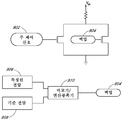
일부 실시예들에서, 스위치를 연결해제하고 정상 동작으로 복귀할지 여부를 결정하는 것은 스위치가 연결해제되는 경우에 전압을 예측하기 위해 PV 모듈의 성능을 모델링하는 것을 포함할 수 있다. 그러한 모델링은 다른 데이터 중에서도 PV 모듈에 대한 데이터, 동작 파라미터들의 실시간 및/또는 이력 측정치, 통신 시스템으로부터의 데이터, 실시간 및/또는 예측 날씨 데이터에 기초할 수 있다. 모델링에 기초하여, 제어기는 정상 동작을 재개하고 스위치(들)를 연결해제할지 여부에 대한 결정을 내릴 수 있다. 제어기는 이어서 정상 동작으로 복귀하고 전압의 모니터링을 재개할 수 있다.In some embodiments, disconnecting the switch and determining whether to return to normal operation may include modeling the performance of the PV module to predict the voltage when the switch is disconnected. Such modeling may be based on data for PV modules, real time and / or historical measurements of operating parameters, data from the communication system, real time and / or forecast weather data among other data. Based on the modeling, the controller may resume normal operation and make a decision as to whether to disconnect the switch (s). The controller can then return to normal operation and resume monitoring the voltage.
정상 동작을 재개하고 스위치(들)를 연결해제할지 여부를 결정하기 위한 다른 방법은 제어기가 각각의 스트링을 연속으로 단락시키면서 남아있는 2개의 스트링들을 개방 상태로 남겨두는 것이다. 3개의 스트링들 각각을 연속으로 단락시킴으로써, 적어도 제어기가 측정을 수행하기에 충분히 긴 시간 동안 임의의 바이패스 모드가 종료될 수 있다. 제어기는, 바이패스 스위치들의 임의의 조합 또는 모든 바이패스 스위치들이 연결해제된다면 생성될 총 전압을 결정하기 위해 연립방정식을 풀도록 구성될 수 있다. 결정된 총 전압이 임계 전압 아래에 있을 때, 제어기는 스위치들을 정상 동작을 위해 구성할 수 있다(그 모듈에 대한 모든 스위치들이 개방됨). 총 전압이 임계 전압 위에 있다면, 제어기는 미리 결정된 전압 제한을 초과함이 없이 최대 전력 생성을 초래하도록 스위치들을 구성할 수 있다.Another way to resume normal operation and determine whether to disconnect the switch (s) is to leave the remaining two strings open, with the controller shorting each string in succession. By shorting each of the three strings in succession, any bypass mode can be terminated at least for a time long enough for the controller to perform the measurement. The controller may be configured to solve the simultaneous equations to determine the total voltage to be generated if any combination of bypass switches or all bypass switches are disconnected. When the determined total voltage is below the threshold voltage, the controller can configure the switches for normal operation (all switches for that module are open). If the total voltage is above the threshold voltage, the controller can configure the switches to cause maximum power generation without exceeding a predetermined voltage limit.
3-스트링 PV 모듈에 대한 실제적인 예로서, 스트링 3이 단락될 수 있으면서 스트링 1 및 스트링 2가 단락되지 않으며, 이때 스트링 1 및 스트링 2는 스트링 1 및 스트링 2로부터의 총 전압 a+b=X를 생성한다. 유사하게, 스트링 1이 단락될 수 있으면서 스트링 2 및 스트링 3이 단락되지 않아, 스트링 2 및 스트링 3으로부터의 총 전압 b+c=Y를 발생시킨다. 총 전압 a+c=Z를 생성하기 위해서 스트링 2가 단락될 수 있으면서 스트링 1 및 스트링 3이 단락되지 않는다. 스트링 1로부터의 전압 기여 a, 스트링 2로부터의 전압 기여 b, 및 스트링 3으로부터의 전압 기여 c를 결정하기 위해 연립방정식을 풀 수 있다. 전압 a, b 및 c는, 총 전압이 안전한지 또는 스트링들 중 하나가 클리핑되어야 하는지를 결정하도록, 합산될 수 있다.As a practical example for a three-string PV module, string 3 can be shorted while string 1 and string 2 are not shorted, where string 1 and string 2 are the total voltage a + b from string 1 and string 2 = X . Similarly, string 1 can be shorted and string 2 and string 3 are not shorted, resulting in total voltage b + c = Y from string 2 and string 3. String 2 can be shorted to produce a total voltage a + c = Z, but string 1 and string 3 are not short-circuited. The simultaneous equations can be solved to determine the voltage contribution a from string 1, the voltage contribution b from string 2, and the voltage contribution c from string 3. The voltages a, b, and c may be summed to determine whether the total voltage is safe or one of the strings should be clipped.
위에서 언급된 바와 같이, 제어기는 전력 생성을 최적화하면서 여전히 미리 결정된 전압 제한 아래에 있도록 어떤 스트링이 클리핑되어야 하는지를 결정할 수 있다. 간단한 수치 예를 사용하면, 모듈에 대한 임계 전압이 60 V이고, 스트링 1과 스트링 2의 합이 50 V로 측정되었고, 스트링 2 및 스트링 3의 합이 45 V로 측정되었으며, 스트링 1과 스트링 3의 합이 45 V로 측정되었다면, 스트링 1로부터의 기여는 25 V이고, 스트링 2로부터의 기여는 25 V이며, 스트링 3으로부터의 기여는 20V라고 결정될 수 있다. 제어기는 스트링 3이 바이패스되고 스트링 1 및 스트링 2가 45 V의 대안예보다 오히려 총 50 V의 총 전압을 위한 출력으로 전압을 제공하도록 최적의 방식으로 스위치들을 구성할 수 있다.As mentioned above, the controller can determine which string should be clipped so that it is still below a predetermined voltage limit while optimizing power generation. Using a simple numerical example, the threshold voltage for the module is 60 V, the sum of string 1 and string 2 is measured at 50 V, the sum of string 2 and string 3 is measured at 45 V, and string 1 and string 3 , The contribution from string 1 is 25 V, the contribution from string 2 is 25 V, and the contribution from string 3 can be determined to be 20 V. The controller can configure the switches in an optimal manner such that the string 3 is bypassed and the string 1 and string 2 provide a voltage to an output for a total voltage of 50 V rather than an alternative of 45 V. [
일 실시예에서, 복수의 태양 전지들을 가로질러 전류가 측정될 수 있다. 측정된 전류에 기초하여, 전압이 추정될 수 있다. 추정된 전압을 이용하여, 전압이 임계 전압을 초과할지 여부가 결정될 수 있다. 이어서, 전압이 안전하며 더 이상 클리핑될 필요가 없다고 결정되면, 스위치(들)가 개방될 수 있다.In one embodiment, current can be measured across a plurality of solar cells. Based on the measured current, the voltage can be estimated. Using the estimated voltage, it can be determined whether the voltage exceeds the threshold voltage. Then, if it is determined that the voltage is safe and no longer needs to be clipped, the switch (s) can be opened.
위에서 언급된 바와 같이, 설명의 많은 부분이 전압 클리핑에 초점을 맞추고 있지만, 도 10의 방법은 전류 클리핑 상황 또는 열점 바이패스 상황에서 동일하게 적용될 수 있다.As mentioned above, although much of the description focuses on voltage clipping, the method of FIG. 10 can be equally applied in current clipping situations or hotpoint bypass situations.
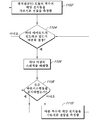
이제 도 11로 돌아가면, 일부 실시예들에 따라, 전압을 클리핑하기 위한 또는 달리 PV 모듈 내의 태양 전지들을 바이패스하기 위한 방법을 나타내는 흐름도가 도시되어 있다. 구체적으로, 흐름도는 바이패스 스위치에 대한 제어 메커니즘을 도시한다. 다양한 실시예들에서, 도 11의 방법은 도시된 것보다 추가적인 (또는 더 적은) 블록들을 포함할 수 있다.Turning now to FIG. 11, a flow diagram is shown illustrating a method for clipping a voltage, or otherwise bypassing solar cells in a PV module, in accordance with some embodiments. Specifically, the flow diagram shows the control mechanism for the bypass switch. In various embodiments, the method of FIG. 11 may include additional (or fewer) blocks than shown.
도 10의 블록(1002)과 유사하게, 단계(1102)에서, PV 모듈의 복수의 태양 전지들을 가로질러 전압이 측정될 수 있다. 다양한 실시예들에서, 전압은 전지, 단일 태양 전지 스트링, 다수의 태양 전지 스트링들, PV 모듈 내의 각각의 태양 전지 스트링을 가로질러, 또는 하나 이상의 모듈을 가로질러 측정될 수 있다. 일 실시예에서, 전압은 전압 클리핑 및/또는 바이패스 회로를 내장하는 접속함 내에 위치된 전압 감지 회로를 이용하여 측정될 수 있다. 다른 실시예들에서, 전압은 PV 라미네이트 내에서 측정될 수 있다.Similar to block 1002 of FIG. 10, at
설명의 많은 부분이 전압의 측정 및 전압의 클리핑에 초점을 맞추고 있지만, 일부 실시예들에서, 단계(1102)에서 전압을 측정하는 것 대신 또는 그에 더하여, 전지, 하나의 전지 스트링, 전지 스트링들, 각각의 전지 스트링을 가로질러, 또는 하나 이상의 모듈을 가로질러 전류가 측정될 수 있다.Although a large portion of the description focuses on measurement of voltage and clipping of voltage, in some embodiments, instead of or in addition to measuring the voltage in
단계(1104)에 도시된 바와 같이, 바디 다이오드(또는 다른 다이오드)가 전도하고 있는지 여부가 결정될 수 있다. 그리고 단계(1006)에 예시된 바와 같이, 다이오드가 전도하고 있다는 결정에 응답하여 하나 이상의 스위치가 폐쇄될 수 있다. 일 실시예에서, 바디 다이오드(또는 다른 다이오드)를 가로지른 전압 강하를 감소시키기 위해 바이패스 상태가 검출될 때 병렬 전도 경로의 스위치를 연결함으로써 전지 스트링 바이패스 동안에 열 소산이 감소될 수 있다. 일 실시예에서, 바디 다이오드를 가로지른 전압이 미리 한정된 범위 내에 있을 때 FET가 온 상태로 될 수 있다.As shown in
단계(1108)에서, 모든 하위시스템들이 검사되었는지 여부가 결정된다. 그렇지 않다면, 일 실시예에서, 제어기는 바이패스 FET를 포함하는 각각의 하위시스템(예컨대, 전지 스트링)에 걸쳐 반복할 수 있으며, FET가 개방된 동안에 FET의 바디 다이오드를 가로지른 전압을 측정할 수 있다. 바디 다이오드가 전도하고 있다고 제어기가 결정하면, 바이패스 상태가 존재하며 제어기는 FET를 폐쇄함으로써 바이패스 스위치를 연결할 것이다. 어느 경우에서든, 제어기는 이어서 프로세스를 재시작하기 위해 다음 하위시스템에 대해 반복하거나 제1 하위시스템으로 리셋할 수 있다.In
일 실시예에서, 병렬 경로를 개방하거나 폐쇄하는 스위치가 외부 시스템 통신(예컨대, 중앙 제어기)에 의존하지 않고 로컬로 제어될 수 있다. 다른 실시예들에서, 분산된 장치들에 대한 유선 또는 무선 통신을 통해 중앙 권한에 의해 절환이 제어될 수 있다. 다른 실시예에서, 중앙 제어기에 의해 로컬 제어기로 전송되는 하나 이상의 파라미터(예컨대, 최대 전압)를 사용하는 로컬 제어기에 의해 절환이 결정될 수 있다. 파라미터는 시스템의 동작 동안에 업데이트될 수 있다.In one embodiment, a switch that opens or closes the parallel path can be locally controlled without relying on external system communications (e.g., a central controller). In other embodiments, switching may be controlled by central authority via wired or wireless communication to the distributed devices. In another embodiment, the switching can be determined by the local controller using one or more parameters (e.g., maximum voltage) that are transmitted by the central controller to the local controller. The parameters may be updated during operation of the system.
개시된 회로의 다양한 구성요소들 및/또는 개시된 기술들의 하나 이상의 부분이 메모리 상에 저장된 프로그램 명령어를 실행하는 프로세서 유닛에 의해 구현될 수 있다. 다양한 실시예들에서, 프로세서 유닛은 하나 이상의 프로세서 또는 코어를 포함할 수 있다. 프로세서 유닛은 캐시(cache) 또는 다른 온-보드 메모리(on-board memory)의 형태를 포함할 수 있다. 메모리는 (예컨대, 프로세서 유닛에 의해 실행가능한 명령어 및 프로세서 유닛에 의해 사용되는 데이터를 저장하기 위해) 프로세서 유닛에 의해 사용가능하다. 메모리는 하드 디스크 저장장치, 플로피 디스크 저장장치, 이동식 디스크 저장장치(removable disk storage), 플래시 메모리, 랜덤 액세스 메모리(RAM-SRAM, EDO RAM, SDRAM, DDR SDRAM, 램버스(Rambus)(등록상표) RAM 등), ROM(PROM, EEPROM 등) 등을 포함하는 임의의 적합한 유형의 물리적 메모리 매체에 의해 구현될 수 있다. 메모리는 일 실시예에서 휘발성 메모리만으로 이루어질 수 있다.One or more portions of the disclosed components and / or disclosed techniques may be implemented by a processor unit executing program instructions stored on a memory. In various embodiments, the processor unit may comprise one or more processors or cores. The processor unit may comprise the form of a cache or other on-board memory. The memory is usable by the processor unit (e.g., to store instructions executable by the processor unit and data used by the processor unit). The memory may be a hard disk storage device, a floppy disk storage device, a removable disk storage, a flash memory, a random access memory (RAM-SRAM, EDO RAM, SDRAM, DDR SDRAM, Rambus RAM , Etc.), ROM (PROM, EEPROM, etc.), and the like. The memory may consist solely of volatile memory in one embodiment.
다양한 실시예들에 따라, 회로는 (예컨대, 임계 전압을 나타내는 값을 수신하기 위해) 다른 장치들에 결합되고 다른 장치들과 통신하도록 구성된 I/O 인터페이스를 포함할 수 있다.According to various embodiments, a circuit may include an I / O interface coupled to other devices (e.g., to receive a value indicative of a threshold voltage) and configured to communicate with other devices.
본 명세서에 개시된 다양한 기술들을 구현하도록 컴퓨터 시스템에 의해 실행가능한 명령어(및 선택적으로 데이터)를 저장하는 제조 물품이 또한 고려된다. 이들 제조 물품은 유형적인(tangible) 컴퓨터 판독가능한 메모리 매체를 포함한다. 고려되는 유형적인 컴퓨터 판독가능한 메모리 매체는 자기 매체(예컨대, 디스크) 또는 광학 매체(예컨대, CD, DVD 및 관련 기술 등)와 같은 저장 매체 또는 메모리 매체뿐만 아니라 컴퓨터 시스템(600)의 메모리 하위시스템의 부분들(제한 없이 SDRAM, DDR SDRAM, RDRAM, SRAM, 플래시 메모리 및 다양한 유형의 ROM 등)을 포함한다. 유형적인 컴퓨터 판독가능한 메모리 매체는 휘발성 또는 비휘발성 메모리일 수 있다.An article of manufacture that also stores instructions (and optionally data) executable by a computer system to implement the various techniques disclosed herein is also contemplated. These articles of manufacture include tangible computer readable memory media. The tangible computer-readable memory media contemplated includes but is not limited to a storage medium or memory medium such as magnetic media (e.g., a disk) or optical media (e.g., CD, DVD and related technologies) (Including, without limitation, SDRAM, DDR SDRAM, RDRAM, SRAM, flash memory, and various types of ROM). The tangible computer readable memory medium may be volatile or nonvolatile memory.
특정 실시예들이 전술되었지만, 특정 특징부에 대해 단일 실시예만이 기술된 경우에도, 이들 실시예는 본 발명의 범주를 제한하도록 의도되지 않는다. 본 개시 내용에 제공된 특징부들의 예들은, 달리 언급되지 않는다면, 제한적이기보다는 예시적인 것으로 의도된다. 상기 설명은, 본 발명의 이익을 갖는 당업자에게 명백하게 되는 바와 같이, 그러한 대안예, 수정예 및 등가물을 포함하고자 의도된다.Although specific embodiments have been described above, even if only a single embodiment is described for a particular feature, these embodiments are not intended to limit the scope of the present invention. Examples of the features provided in this disclosure are intended to be illustrative rather than restrictive unless otherwise stated. The above description is intended to cover such alternatives, modifications, and equivalents as will be apparent to those skilled in the art having the benefit of this disclosure.
본 발명의 범주는, 본 명세서에서 다루어지는 문제들 중 어느 문제 또는 모든 문제점들을 완화시키든 그렇지 않든 간에, 본 명세서에 (명백히 또는 암시적으로) 개시된 임의의 특징부 또는 특징부들의 조합, 또는 이들의 임의의 일반화를 포함한다. 따라서, 특징부들의 임의의 그러한 조합에 대해, 본 출원(또는 이에 대한 우선권을 주장하는 출원)의 진행 동안에 신규 청구항이 만들어질 수 있다. 특히, 첨부된 청구범위를 참조하여, 종속항으로부터의 특징부가 독립항의 특징부와 조합될 수 있고, 각자의 독립항으로부터의 특징부들은 첨부된 청구범위 내에서 열거된 특정 조합들 내에서만이 아니라 임의의 적당한 방식으로 조합될 수 있다.The scope of the present invention includes any feature or combination of features disclosed herein (whether explicitly or implicitly), whether or not mitigating any or all of the problems addressed herein, ≪ / RTI > Thus, for any such combination of features, a new claim can be made during the course of the present application (or a priority application). In particular, and with reference to the appended claims, features from the dependent claims may be combined with features of the independent claim, and features from their respective independent claims may be incorporated within specific combinations listed within the appended claims, In a suitable manner.
일 실시예에서, 광기전(PV) 모듈은 복수의 태양 전지들, 및 PV 모듈로부터의 출력 전압이 복수의 태양 전지들로부터의 전압을 포함하는 제1 상태와 복수의 태양 전지들의 적어도 일부가 출력 전압에의 전압의 제공으로부터 바이패스되는 제2 상태 사이에서 절환하도록 구성되는 회로를 포함한다.In one embodiment, the photovoltaic (PV) module comprises a plurality of solar cells, and a first state in which the output voltage from the PV module comprises a voltage from a plurality of solar cells, and at least a portion of the plurality of solar cells, And a second state that is bypassed from provision of a voltage to the voltage.
일 실시예에서, 회로는 제1 상태와 제2 상태 사이에서 절환하도록 구성된 전자 스위치를 포함한다.In one embodiment, the circuit includes an electronic switch configured to switch between a first state and a second state.
일 실시예에서, 복수의 태양 전지들이 복수의 태양 전지 스트링들을 포함하고, 제2 상태에서 복수의 태양 전지 스트링들 중 하나 이상의 스트링이 출력 전압에의 제공으로부터 바이패스된다.In one embodiment, the plurality of solar cells comprises a plurality of solar cell strings, and in the second state, one or more strings of the plurality of solar cell strings are bypassed from providing to the output voltage.
일 실시예에서, 회로는 복수의 태양 전지 스트링들의 각각의 스트링에 대응하는 별개의 스위치를 포함한다.In one embodiment, the circuit includes a separate switch corresponding to a string of each of the plurality of solar cell strings.
일 실시예에서, 제2 상태에서, 별개의 스위치들 중 적어도 하나는 그의 대응하는 태양 전지 스트링을 바이패스하도록 폐쇄된다.In one embodiment, in the second state, at least one of the separate switches is closed to bypass its corresponding solar cell string.
일 실시예에서, 제2 상태에서의 PV 모듈로부터의 출력 전압은 제1 상태에서의 PV 모듈로부터의 출력 전압보다 대략 25% 더 낮다.In one embodiment, the output voltage from the PV module in the second state is approximately 25% lower than the output voltage from the PV module in the first state.
일 실시예에서, PV 모듈은 전압을 감지하도록 구성된 전압 감지 장치를 더 포함하고, 회로는 임계 전압을 초과하는 감지된 전압에 기초하여 제1 상태로부터 제2 상태로 절환하도록 구성된다.In one embodiment, the PV module further comprises a voltage sensing device configured to sense voltage, and the circuit is configured to switch from the first state to the second state based on the sensed voltage exceeding the threshold voltage.
일 실시예에서, PV 모듈은 복수의 태양 전지들 중 하나 이상으로부터의 전류를 제한하도록 구성되는 추가 회로를 더 포함한다.In one embodiment, the PV module further comprises additional circuitry configured to limit the current from one or more of the plurality of solar cells.
일 실시예에서, 회로는 스위치, 및 스위치와 병렬인 다이오드를 포함한다.In one embodiment, the circuit includes a switch, and a diode in parallel with the switch.
일 실시예에서, 전압 제한 장치는 광기전 모듈로부터의 출력 전압이 광기전 모듈의 복수의 태양전지 스트링들의 각각의 스트링으로부터의 전압을 포함하는 제1 상태와 광기전 모듈로부터의 출력 전압이 복수의 태양전지 스트링들 전부보다 적은 태양전지 스트링들로부터의 전압을 포함하는 제2 상태 사이에서 절환하도록 구성되는 회로를 포함한다.In one embodiment, the voltage-limiting device includes a first state in which the output voltage from the photovoltaic module comprises a voltage from each string of a plurality of solar cell strings of the photovoltaic module, and a second state in which the output voltage from the photovoltaic module comprises a plurality And a second state comprising a voltage from solar cell strings that is less than all of the solar cell strings.
일 실시예에서, 회로는 복수의 태양 전지 스트링들의 각각의 스트링에 대응하는 각자의 스위치를 포함한다.In one embodiment, the circuit includes a respective switch corresponding to a string of each of the plurality of solar cell strings.
일 실시예에서, 제2 상태에서, 출력 전압은 제1 상태에서의 출력 전압보다 대략 25% 더 낮다.In one embodiment, in the second state, the output voltage is approximately 25% lower than the output voltage in the first state.
일 실시예에서, 회로는 태양 전지 스트링의 전압이 0V로 강하하는 것에 응답하여 전류를 제한하도록 구성된다.In one embodiment, the circuit is configured to limit the current in response to the voltage of the solar cell string dropping to 0V.
일 실시예에서, 전류를 제한하도록 구성되는 회로는 태양 전지 스트링의 전압이 0V로 강하하는 것에 응답하여 전류를 제한하도록 구성되는 하나 이상의 스위치를 포함한다.In one embodiment, the circuit configured to limit the current includes one or more switches configured to limit the current in response to the voltage of the solar cell string dropping to 0V.
일 실시예에서, 광기전(PV) 모듈의 하나 이상의 전지를 바이패스하기 위한 방법은 PV 모듈의 복수의 태양 전지들을 가로지른 전압을 측정하는 단계; 전압이 임계치를 초과하는지 또는 임계치 아래로 떨어지는지 여부를 결정하는 단계; 및In one embodiment, a method for bypassing one or more cells of a photovoltaic (PV) module comprises: measuring a voltage across a plurality of solar cells of the PV module; Determining whether the voltage exceeds a threshold or falls below a threshold; And
전압이 임계치를 초과하거나 임계치 아래로 떨어진다는 결정에 응답하여, 복수의 태양 전지들 중 하나 이상을 바이패스하도록 하나 이상의 스위치를 폐쇄하는 단계를 포함한다.And closing one or more switches to bypass one or more of the plurality of solar cells in response to determining that the voltage exceeds or falls below the threshold.
일 실시예에서, 상기 결정하는 단계는 전압이 임계치를 초과한다고 결정하는 단계를 포함하며, 상기 하나 이상의 스위치를 폐쇄하는 단계는 하나 이상의 태양 전지로부터의 전압이 PV 모듈의 출력 전압에 제공되는 것을 방지하게 한다.In one embodiment, the determining comprises determining that the voltage exceeds a threshold, wherein closing the one or more switches prevents the voltage from one or more solar cells from being provided to the output voltage of the PV module .
일 실시예에서, 이 방법은 PV 모듈의 복수의 태양 전지들을 가로지른 전류를 측정하는 단계; 측정된 전류에 기초하여, 전압이 임계치를 초과하지 않을 것이라고 결정하는 단계; 및 복수의 태양 전지들 중 하나 이상의 태양 전지로부터의 전압이 PV 모듈의 출력 전압에 제공되는 것을 허용하도록 하나 이상의 스위치를 개방하는 단계를 더 포함한다.In one embodiment, the method comprises the steps of measuring a current across a plurality of solar cells of a PV module; Determining, based on the measured current, that the voltage will not exceed the threshold; And opening one or more switches to allow a voltage from one or more of the plurality of solar cells to be provided to an output voltage of the PV module.
일 실시예에서, 상기 결정하는 단계는 전압이 대략 0V의 임계치 아래로 떨어진다고 결정하는 단계를 포함한다.In one embodiment, the determining comprises determining that the voltage falls below a threshold of approximately 0V.
일 실시예에서, 하나 이상의 스위치를 폐쇄하는 단계는 태양 전지 스트링이 출력 전압에 전압을 제공하는 것을 방지하도록 단일 스위치를 폐쇄하는 단계를 포함한다.In one embodiment, closing one or more switches includes closing a single switch to prevent the solar cell string from providing a voltage to the output voltage.
일 실시예에서, 이 방법은 일정 기간을 대기하는 단계; 하나 이상의 스위치를 개방하는 단계; 및 PV 모듈의 복수의 태양 전지들을 가로지른 전압을 측정하는 단계를 더 포함한다.In one embodiment, the method includes waiting a period of time; Opening one or more switches; And measuring a voltage across the plurality of solar cells of the PV module.
Claims (20)
복수의 태양 전지들;
PV 모듈로부터의 출력 전압이 복수의 태양 전지들로부터의 전압을 포함하는 제1 상태와 복수의 태양 전지들의 적어도 일부가 출력 전압에의 전압의 제공으로부터 바이패스되는 제2 상태 사이에서 절환하도록 구성되는 회로를 포함하는, 광기전 모듈.As a photovoltaic (PV) module,
A plurality of solar cells;
A first state in which the output voltage from the PV module includes a voltage from a plurality of solar cells and a second state in which at least a portion of the plurality of solar cells is bypassed from provision of a voltage to the output voltage A photovoltaic module comprising a circuit.
회로는 임계 전압을 초과하는 감지된 전압에 기초하여 제1 상태로부터 제2 상태로 절환하도록 구성되는, 광기전 모듈.The apparatus of claim 1, further comprising a voltage sensing device configured to sense a voltage,
Wherein the circuit is configured to switch from a first state to a second state based on a sensed voltage that exceeds a threshold voltage.
광기전 모듈로부터의 출력 전압이 광기전 모듈의 복수의 태양전지 스트링들의 각각의 스트링으로부터의 전압을 포함하는 제1 상태와 광기전 모듈로부터의 출력 전압이 복수의 태양전지 스트링들 전부보다 적은 태양전지 스트링들로부터의 전압을 포함하는 제2 상태 사이에서 절환하도록 구성되는 회로를 포함하는, 전압 제한 장치.As a voltage limiting device,
A first state in which the output voltage from the photovoltaic module comprises a voltage from each string of a plurality of solar cell strings of the photovoltaic module and a first state in which the output voltage from the photovoltaic module is less than all solar cell strings And a second state comprising a voltage from the strings.
PV 모듈의 복수의 태양 전지들을 가로지른 전압을 측정하는 단계;
전압이 임계치를 초과하는지 또는 임계치 아래로 떨어지는지 여부를 결정하는 단계; 및
전압이 임계치를 초과하거나 임계치 아래로 떨어진다는 결정에 응답하여, 복수의 태양 전지들 중 하나 이상을 바이패스하도록 하나 이상의 스위치를 폐쇄하는 단계를 포함하는, 방법.A method for bypassing one or more cells of a photovoltaic (PV) module,
Measuring a voltage across the plurality of solar cells of the PV module;
Determining whether the voltage exceeds a threshold or falls below a threshold; And
Closing the one or more switches to bypass one or more of the plurality of solar cells in response to determining that the voltage exceeds or falls below a threshold.
PV 모듈의 복수의 태양 전지들을 가로지른 전류를 측정하는 단계;
측정된 전류에 기초하여, 전압이 임계치를 초과하지 않을 것이라고 결정하는 단계; 및
복수의 태양 전지들 중 하나 이상의 태양 전지로부터의 전압이 PV 모듈의 출력 전압에 제공되는 것을 허용하도록 하나 이상의 스위치를 개방하는 단계를 더 포함하는, 방법.17. The method of claim 16,
Measuring a current across the plurality of solar cells of the PV module;
Determining, based on the measured current, that the voltage will not exceed the threshold; And
Further comprising opening one or more switches to allow a voltage from one or more solar cells of the plurality of solar cells to be provided to an output voltage of the PV module.
일정 기간을 대기하는 단계;
하나 이상의 스위치를 개방하는 단계; 및
PV 모듈의 복수의 태양 전지들을 가로지른 전압을 측정하는 단계를 더 포함하는, 방법.16. The method of claim 15,
Waiting for a certain period of time;
Opening one or more switches; And
Further comprising measuring a voltage across the plurality of solar cells of the PV module.
Applications Claiming Priority (5)
| Application Number | Priority Date | Filing Date | Title |
|---|---|---|---|
| US201361916800P | 2013-12-17 | 2013-12-17 | |
| US61/916,800 | 2013-12-17 | ||
| US14/572,722 US10211631B2 (en) | 2013-12-17 | 2014-12-16 | Voltage clipping |
| US14/572,722 | 2014-12-16 | ||
| PCT/US2014/070987 WO2015095414A1 (en) | 2013-12-17 | 2014-12-17 | Voltage clipping |
Publications (1)
| Publication Number | Publication Date |
|---|---|
| KR20160099560A true KR20160099560A (en) | 2016-08-22 |
Family
ID=53369649
Family Applications (1)
| Application Number | Title | Priority Date | Filing Date |
|---|---|---|---|
| KR1020167015730A KR20160099560A (en) | 2013-12-17 | 2014-12-17 | Voltage clipping |
Country Status (10)
| Country | Link |
|---|---|
| US (1) | US10211631B2 (en) |
| EP (1) | EP3084956A4 (en) |
| JP (1) | JP2017502490A (en) |
| KR (1) | KR20160099560A (en) |
| CN (1) | CN105723614A (en) |
| AU (1) | AU2014364597B2 (en) |
| CL (1) | CL2016001399A1 (en) |
| MX (1) | MX2016007330A (en) |
| WO (1) | WO2015095414A1 (en) |
| ZA (1) | ZA201603514B (en) |
Families Citing this family (25)
| Publication number | Priority date | Publication date | Assignee | Title |
|---|---|---|---|---|
| US10211631B2 (en) | 2013-12-17 | 2019-02-19 | Enphase Energy, Inc. | Voltage clipping |
| US10431987B2 (en) * | 2015-09-24 | 2019-10-01 | Sunpower Corporation | Methods and systems for maintaining photovoltaic power plant reactive power capability |
| US10819215B2 (en) * | 2016-06-30 | 2020-10-27 | University Of South Carolina | Bypass switch for high voltage DC systems |
| US10218182B2 (en) * | 2016-09-22 | 2019-02-26 | Sunpower Corporation | Photovoltaic systems with voltage limiting devices |
| DE102016118039A1 (en) | 2016-09-23 | 2018-03-29 | Sma Solar Technology Ag | Solar module, photovoltaic system and voltage limiting method |
| JP6536552B2 (en) * | 2016-12-12 | 2019-07-03 | トヨタ自動車株式会社 | Solar power system |
| US10396593B1 (en) | 2017-07-05 | 2019-08-27 | Sunpower Corporation | Rapid shutdown of photovoltaic systems |
| CN109818569B (en) * | 2017-11-18 | 2021-06-08 | 丰郅(上海)新能源科技有限公司 | Parallel type turn-off system for photovoltaic module and method for restarting after turn-off |
| WO2019205289A1 (en) * | 2018-04-28 | 2019-10-31 | 北京汉能光伏投资有限公司 | Solar component junction box, solar system and solar component control method |
| CN109067353B (en) | 2018-08-24 | 2020-03-24 | 阳光电源股份有限公司 | Active bypass control device and method for photovoltaic module |
| CN111564866A (en) * | 2019-02-14 | 2020-08-21 | 阳光电源股份有限公司 | Component voltage limiting method and application device and system thereof |
| CN111565021A (en) * | 2019-02-14 | 2020-08-21 | 阳光电源股份有限公司 | Component voltage limiting circuit and application device thereof |
| CN111565020A (en) * | 2019-02-14 | 2020-08-21 | 阳光电源股份有限公司 | Component voltage limiting method and application device and system thereof |
| EP3905465B1 (en) * | 2019-07-11 | 2023-12-06 | Huawei Digital Power Technologies Co., Ltd. | Converter, method and system applied to photovoltaic power generation system |
| WO2021107198A1 (en) * | 2019-11-28 | 2021-06-03 | 전자부품연구원 | Energy harvesting system using multiple surrounding energy sources |
| US20210184468A1 (en) * | 2019-12-13 | 2021-06-17 | Ge Energy Power Conversion Technology Limited | Bypass module for enhanced pv array dc-ac ratio capability |
| DE102020101809A1 (en) | 2020-01-27 | 2021-07-29 | Hanwha Q Cells Gmbh | Solar cell module and method for operating a solar cell module |
| RU200793U1 (en) * | 2020-02-28 | 2020-11-11 | Общество с ограниченной ответственностью «МТД ПРАЙМ» | Portable photovoltaic power supply |
| CN111668868A (en) * | 2020-05-08 | 2020-09-15 | 华为技术有限公司 | Photovoltaic power generation system and method |
| US10992149B1 (en) * | 2020-10-08 | 2021-04-27 | Element Energy, Inc. | Safe battery energy management systems, battery management system nodes, and methods |
| US11791642B2 (en) | 2020-10-08 | 2023-10-17 | Element Energy, Inc. | Safe battery energy management systems, battery management system nodes, and methods |
| US11913362B2 (en) | 2020-11-30 | 2024-02-27 | Rondo Energy, Inc. | Thermal energy storage system coupled with steam cracking system |
| WO2022115721A2 (en) | 2020-11-30 | 2022-06-02 | Rondo Energy, Inc. | Energy storage system and applications |
| US11913361B2 (en) | 2020-11-30 | 2024-02-27 | Rondo Energy, Inc. | Energy storage system and alumina calcination applications |
| DE102021211448A1 (en) | 2021-10-11 | 2023-04-13 | Fraunhofer-Gesellschaft zur Förderung der angewandten Forschung eingetragener Verein | Electronic circuit for a photovoltaic module and method for connecting a photovoltaic module |
Family Cites Families (39)
| Publication number | Priority date | Publication date | Assignee | Title |
|---|---|---|---|---|
| JPH05284668A (en) | 1992-03-30 | 1993-10-29 | Shin Kobe Electric Mach Co Ltd | Solar generating system |
| US5584974A (en) * | 1995-10-20 | 1996-12-17 | Eni | Arc control and switching element protection for pulsed dc cathode sputtering power supply |
| JP2000114567A (en) | 1998-08-03 | 2000-04-21 | Canon Inc | Solar battery module and solar power generating system |
| US7714550B2 (en) * | 2005-01-24 | 2010-05-11 | Linear Technology Corporation | System and method for tracking a variable characteristic through a range of operation |
| JP2006287164A (en) | 2005-04-05 | 2006-10-19 | Sharp Corp | Solar power generation device |
| JP4776348B2 (en) | 2005-11-11 | 2011-09-21 | シャープ株式会社 | Inverter device |
| US10693415B2 (en) * | 2007-12-05 | 2020-06-23 | Solaredge Technologies Ltd. | Testing of a photovoltaic panel |
| TW200830687A (en) * | 2007-01-15 | 2008-07-16 | zhen-yue Fan | Control apparatus of solar power system |
| FR2912848B1 (en) | 2007-02-20 | 2010-09-17 | Commissariat Energie Atomique | VOLTAGE LIMITER AND PROTECTION OF A PHOTOVOLTAIC MODULE |
| AU2009202125B2 (en) | 2008-05-29 | 2014-02-13 | Zener International Pty Ltd | Photovoltaic Array Protection System |
| US8115340B2 (en) * | 2008-12-12 | 2012-02-14 | Paceco Corp. | System for controlling power from a photovoltaic array by selectively configurating connections between photovoltaic panels |
| US8050804B2 (en) * | 2008-12-15 | 2011-11-01 | Array Converter, Inc. | Detection and prevention of hot spots in a solar panel |
| US8102074B2 (en) | 2009-07-30 | 2012-01-24 | Tigo Energy, Inc. | Systems and method for limiting maximum voltage in solar photovoltaic power generation systems |
| PT2457258E (en) * | 2009-08-26 | 2016-02-26 | Fraunhofer Ges Zur Fã Rderung Der Angewandten Forschung E V | Bypass and protection circuit for a solar module and method for controlling a solar module |
| US8263920B2 (en) * | 2009-09-30 | 2012-09-11 | The Boeing Company | Diodeless terrestrial photovoltaic solar power array |
| US9324885B2 (en) * | 2009-10-02 | 2016-04-26 | Tigo Energy, Inc. | Systems and methods to provide enhanced diode bypass paths |
| US9035491B2 (en) * | 2009-11-16 | 2015-05-19 | Omron Corporation | Voltage setting device, photovoltaic power generation system, and control method of voltage setting device |
| EP2325984A1 (en) | 2009-11-24 | 2011-05-25 | SMA Solar Technology AG | Start up of a photovoltiac field with high open circuit voltage |
| JP2012088916A (en) * | 2010-10-19 | 2012-05-10 | Mitsubishi Electric Corp | Photovoltaic power generation system |
| US9018800B2 (en) * | 2010-11-19 | 2015-04-28 | Texas Instruments Incorporated | High efficiency wide load range buck/boost/bridge photovoltaic micro-converter |
| US20130321013A1 (en) * | 2010-12-02 | 2013-12-05 | Dow Global Technologies Llc | Photovoltaic device for measuring irradiance and temperature |
| US9006940B2 (en) * | 2011-01-28 | 2015-04-14 | Bette Korman | Modular portable energy system |
| JP5626798B2 (en) | 2011-02-04 | 2014-11-19 | シャープ株式会社 | Photovoltaic power generation system, switching system, and bypass device |
| CN102111080B (en) * | 2011-02-24 | 2013-09-18 | 广州智光电气股份有限公司 | Photovoltaic grid-connected inverter and control method |
| US9300153B2 (en) * | 2011-05-12 | 2016-03-29 | Sharp Kabushiki Kaisha | Charging control unit |
| US20120298166A1 (en) * | 2011-05-24 | 2012-11-29 | Rfmarq, Inc. | Solar Panel with Energy Efficient Bypass Diode System |
| US9472691B2 (en) | 2011-08-25 | 2016-10-18 | Sunpower Corporation | Device for shunting current from photovoltaic circuit near the open circuit voltage and/or disconnecting solar module of a solar system |
| GB201116253D0 (en) | 2011-09-20 | 2011-11-02 | Eight19 Ltd | Photovoltaic device |
| US9276402B2 (en) | 2011-11-07 | 2016-03-01 | Fairchild Semiconductor Corporation | Photovoltaic system power optimization |
| US8630077B2 (en) | 2011-12-22 | 2014-01-14 | Sunpower Corporation | Circuits and methods for limiting open circuit voltage of photovoltaic strings |
| GB2498365A (en) | 2012-01-11 | 2013-07-17 | Solaredge Technologies Ltd | Photovoltaic module |
| US9000615B2 (en) | 2012-02-04 | 2015-04-07 | Sunfield Semiconductor Inc. | Solar power module with safety features and related method of operation |
| TW201349731A (en) | 2012-05-30 | 2013-12-01 | Delta Electronics Inc | Photovoltaic power system with generation modules and method of controlling output power thereof |
| US9269834B2 (en) | 2012-06-29 | 2016-02-23 | Nxp B.V. | Photovoltaic module monitoring and control |
| US9178353B2 (en) * | 2013-03-27 | 2015-11-03 | Sunfield Semiconductor, Inc. | Active bypass diode circuit and solar power module with arc flash mitigation feature |
| WO2014186300A1 (en) * | 2013-05-12 | 2014-11-20 | Solexel, Inc. | Solar photovoltaic blinds and curtains for residential and commercial buildings |
| US20150130281A1 (en) * | 2013-11-10 | 2015-05-14 | S. Shey Sabripour | Integrated Energy Module |
| US10211631B2 (en) | 2013-12-17 | 2019-02-19 | Enphase Energy, Inc. | Voltage clipping |
| AU2015267158B2 (en) * | 2014-05-27 | 2020-08-06 | Sunpower Corporation | Photovoltaic system protection |
-
2014
- 2014-12-16 US US14/572,722 patent/US10211631B2/en active Active
- 2014-12-17 KR KR1020167015730A patent/KR20160099560A/en not_active Application Discontinuation
- 2014-12-17 AU AU2014364597A patent/AU2014364597B2/en not_active Expired - Fee Related
- 2014-12-17 EP EP14871646.7A patent/EP3084956A4/en not_active Withdrawn
- 2014-12-17 WO PCT/US2014/070987 patent/WO2015095414A1/en active Application Filing
- 2014-12-17 JP JP2016519960A patent/JP2017502490A/en active Pending
- 2014-12-17 MX MX2016007330A patent/MX2016007330A/en unknown
- 2014-12-17 CN CN201480061748.0A patent/CN105723614A/en active Pending
-
2016
- 2016-05-23 ZA ZA2016/03514A patent/ZA201603514B/en unknown
- 2016-06-08 CL CL2016001399A patent/CL2016001399A1/en unknown
Also Published As
| Publication number | Publication date |
|---|---|
| JP2017502490A (en) | 2017-01-19 |
| WO2015095414A1 (en) | 2015-06-25 |
| CL2016001399A1 (en) | 2017-02-17 |
| AU2014364597B2 (en) | 2018-12-06 |
| AU2014364597A1 (en) | 2016-04-07 |
| EP3084956A1 (en) | 2016-10-26 |
| ZA201603514B (en) | 2018-11-28 |
| EP3084956A4 (en) | 2016-11-23 |
| US10211631B2 (en) | 2019-02-19 |
| MX2016007330A (en) | 2016-08-19 |
| CN105723614A (en) | 2016-06-29 |
| US20150171628A1 (en) | 2015-06-18 |
Similar Documents
| Publication | Publication Date | Title |
|---|---|---|
| KR20160099560A (en) | Voltage clipping | |
| US10461570B2 (en) | Systems and methods to provide enhanced diode bypass paths | |
| EP3657622B1 (en) | Photovoltaic power optimizer and control method and apparatus therefor, and photovoltaic power generation system | |
| EP3739349B1 (en) | Fault tolerant fail-safe link comprising parallel branches | |
| US8344544B2 (en) | Bus-tie SSPCS for DC power distribution system | |
| JP5743739B2 (en) | Power storage device | |
| JP5852454B2 (en) | Solar cell module and solar power generation system | |
| US8213134B2 (en) | Apparatus, system, and method to prevent smoke in a power supply powered by a current limited source | |
| WO2013153889A1 (en) | Battery pack provided with charge and discharge control switch circuit | |
| US10700536B2 (en) | Control device, balance correcting system, electric storage system and device | |
| TW201508296A (en) | Detecting faults in hot-swap applications | |
| JP2007157700A (en) | Power circuit protection device using superconductor | |
| US20140373895A1 (en) | Solar cell unit and solar cell module | |
| JPH02266834A (en) | Cell by pass circuit | |
| KR101838760B1 (en) | System for the electronic management of photovoltaic cells as a function of meteorology | |
| US20160087421A1 (en) | Protection of a power supply including a plurality of batteries in parallel against an external short circuit | |
| TWI502853B (en) | Short circuit control for high current pulse power supply | |
| US9397652B2 (en) | Circuitry and method for operating such circuitry | |
| JP5491666B1 (en) | Solar cell characteristic measuring device | |
| CN207442809U (en) | A kind of solid-state relay | |
| US20140071568A1 (en) | DC Power Source Isolation with Diode and Bypass Switch | |
| KR102065735B1 (en) | Apparatus and method for managing battery pack | |
| US20230198249A1 (en) | Circuit breaker with pre-charging and current limiting functions, method of operating same, power supply circuit and aircraft | |
| TW202335401A (en) | Persistent dc power and control switch | |
| CN116031862A (en) | Vehicle power distribution circuit and vehicle power system |
Legal Events
| Date | Code | Title | Description |
|---|---|---|---|
| N231 | Notification of change of applicant | ||
| E902 | Notification of reason for refusal | ||
| E90F | Notification of reason for final refusal | ||
| E601 | Decision to refuse application |