KR20160097529A - Floating Crane for Installation Offshore Wind Tower - Google Patents
Floating Crane for Installation Offshore Wind Tower Download PDFInfo
- Publication number
- KR20160097529A KR20160097529A KR1020150019301A KR20150019301A KR20160097529A KR 20160097529 A KR20160097529 A KR 20160097529A KR 1020150019301 A KR1020150019301 A KR 1020150019301A KR 20150019301 A KR20150019301 A KR 20150019301A KR 20160097529 A KR20160097529 A KR 20160097529A
- Authority
- KR
- South Korea
- Prior art keywords
- wind tower
- lifting fork
- winch
- pulley
- wire rope
- Prior art date
Links
Images


Classifications
-
- B—PERFORMING OPERATIONS; TRANSPORTING
- B66—HOISTING; LIFTING; HAULING
- B66C—CRANES; LOAD-ENGAGING ELEMENTS OR DEVICES FOR CRANES, CAPSTANS, WINCHES, OR TACKLES
- B66C23/00—Cranes comprising essentially a beam, boom, or triangular structure acting as a cantilever and mounted for translatory of swinging movements in vertical or horizontal planes or a combination of such movements, e.g. jib-cranes, derricks, tower cranes
- B66C23/18—Cranes comprising essentially a beam, boom, or triangular structure acting as a cantilever and mounted for translatory of swinging movements in vertical or horizontal planes or a combination of such movements, e.g. jib-cranes, derricks, tower cranes specially adapted for use in particular purposes
- B66C23/36—Cranes comprising essentially a beam, boom, or triangular structure acting as a cantilever and mounted for translatory of swinging movements in vertical or horizontal planes or a combination of such movements, e.g. jib-cranes, derricks, tower cranes specially adapted for use in particular purposes mounted on road or rail vehicles; Manually-movable jib-cranes for use in workshops; Floating cranes
- B66C23/52—Floating cranes
- B66C23/53—Floating cranes including counterweight or means to compensate for list, trim, or skew of the vessel or platform
-
- B—PERFORMING OPERATIONS; TRANSPORTING
- B63—SHIPS OR OTHER WATERBORNE VESSELS; RELATED EQUIPMENT
- B63B—SHIPS OR OTHER WATERBORNE VESSELS; EQUIPMENT FOR SHIPPING
- B63B21/00—Tying-up; Shifting, towing, or pushing equipment; Anchoring
- B63B21/24—Anchors
-
- B—PERFORMING OPERATIONS; TRANSPORTING
- B63—SHIPS OR OTHER WATERBORNE VESSELS; RELATED EQUIPMENT
- B63B—SHIPS OR OTHER WATERBORNE VESSELS; EQUIPMENT FOR SHIPPING
- B63B21/00—Tying-up; Shifting, towing, or pushing equipment; Anchoring
- B63B21/50—Anchoring arrangements or methods for special vessels, e.g. for floating drilling platforms or dredgers
Landscapes
- Engineering & Computer Science (AREA)
- Mechanical Engineering (AREA)
- Chemical & Material Sciences (AREA)
- Combustion & Propulsion (AREA)
- Ocean & Marine Engineering (AREA)
- Wind Motors (AREA)
Abstract
Description
본 발명은 풍력타워를 설치하기 위한 해상 크레인에 관한 것으로, 더욱 상세하게는 해상에서 대형의 특수크레인을 사용하지 않고도 해상에 설치된 기초구조물에 풍력타워를 용이하게 설치할 수 있고, 해상 크레인에서 리프팅 포크의 평형을 유지시키고 리프팅 포크가 좌우로 흔들리는 것을 방지할 수 있도록 하며, 풍력타워를 설치할 때 풍력타워가 좌우로 흔들리거나 회전하는 것을 방지하여 안정성을 제고할 수 있는 해상 크레인에 관한 것이다.
The present invention relates to a floating crane for installing a wind tower, and more particularly, to a floating crane capable of easily installing a wind tower on a foundation structure installed on the sea without using a large special crane at sea, The present invention relates to a marine crane capable of maintaining the balance and preventing the lifting fork from being shaken to the left and right and enhancing stability by preventing the wind tower from shaking or rotating from side to side when the wind tower is installed.
일반적으로 풍력발전은 신재생에너지로 자원이 풍부하고 끊임없이 재생되며, 광범위한 지역에 분포되어 있을 뿐만 아니라 청정하고 전력생산에 따른 온실가스의 배출이 없는 등 화석에너지의 고갈에 대비한 대체에너지원으로 각광받고 있다.Generally, wind power generation is a renewable energy resource rich and constantly reproduced. It is distributed not only in a wide area but also as a clean energy source, and it does not emit greenhouse gas due to power generation. .
풍력발전은 자연에너지인 바람을 이용하여 발전하기 때문에 바람이 불 때에는 수요에 관계없이 반드시 전력을 생산한다는 점에서 계통운용 측면에서 분산전원으로 분류된다.Wind power generation is classified as a distributed power supply in terms of system operation in that it generates electricity regardless of demand when the wind is blowing because it is developed using wind, which is natural energy.
풍력발전기 시스템은 주요 구성으로 기계시스템, 전기시스템 및 풍력발전기를 제어하는 제어시스템으로 구분된다. 또한, 블레이드를 포함하는 허브시스템과, 각종 기계, 전기, 제어장치 등이 탑재된 넛셀(Nutshell), 그리고 상부의 허브시스템과 넛셀의 중량을 지상으로부터 지지하기 위한 타워시스템으로도 구분된다.Wind turbine systems are divided into mechanical systems, electrical systems, and control systems that control wind turbines. Also, it is divided into a hub system including a blade, a nutshell equipped with various machines, an electric and a control device, and a hub system at the upper part and a tower system for supporting the weight of the nun cell from the ground.
풍력발전기는 설치 장소에 따라 육상용과 해상용으로 나누어진다. 특히 해상 풍력발전은 물속이나 물 위에 풍력발전단지의 건설로 바람에 의한 전력생산이 가능하도록 하는 것으로, 해상이라는 관점은 바다뿐만 아니라 호수나 협강, 폐쇄된 해안지역 등 내륙에 속하는 지역의 풍력발전도 포함된다. 더욱이 해상의 풍력발전은 육상보다 안정적이고 양호한 풍속을 얻을 수 있고, 장애물이나 소음 및 전파장애도 적으며, 대형화된 풍력발전기의 운반 및 설치와 시공비용의 절감을 도모할 수 있고, 대규모의 전력소비지역이 대부분 연안에 위치하고 있어 송전비용 측면에서도 유리한 점이 있다.Wind turbines are divided into land and marine types depending on the installation location. In particular, offshore wind power generation enables the production of wind power by the construction of wind power generation complexes in water or on water. From the point of view of the sea, not only the sea, but also the inland areas such as lakes, . Moreover, the offshore wind power generation is more stable than the onshore wind turbine, has good wind speed, has few obstacles, noise and propagation obstacles, can be used for the transportation and installation of large-sized wind power generators, Since most of the area is located on the coast, there is an advantage in terms of transmission cost.
종래에 해상에 설치되는 풍력발전기는 육상에서 제작한 후에 바지선에 선적하여 설치 해역까지 예인선으로 예인한 후에 대형의 크레인이 설치된 기중기선을 이용하여 풍력발전기를 해상에 설치된 기초구조물에 기립하여 설치하고 있다. 또한, 풍력발전기의 주요 구성요소들을 해상에서 직접 조립 및 설치하고 있다. 즉 대략 1~3단의 풍력타워의 조립과 허브 조립, 그리고 블레이드 조립 등을 동시에 또는 하나씩 조립한 후에 대형의 기중기선에 설치된 크레인을 이용하여 위로 들어 올려야 한다. 이는 크레인의 하중 능력보다 붐의 높이가 중요한 인자가 된다.Conventionally, a wind turbine installed on the sea has been constructed on land, then loaded on a barge, towed to a tug to the installation area, and installed on a foundation structure installed on the sea using a crane line equipped with a large crane . In addition, major components of wind turbines are assembled and installed directly at sea. That is, it is necessary to assemble the wind tower of about 1 ~ 3 stages, the hub assembly, and the blade assembly at the same time or after assembling them one by one, and then lift it up by using a crane installed on a large crane line. The height of the boom is more important factor than the load capacity of the crane.
풍력발전기의 효율적인 발전을 위하여 해상에서도 풍력발전기의 높이가 점점 높아지는 추세이고 그 길이는 대략 80~130m에 이르며, 이러한 풍력발전기를 수직으로 들어 올릴 수 있는 대형 크레인이 설치된 기중기선의 보급이 어려운 실정이다. 더욱이 심도가 있는 해상에서 풍력발전기의 설치는 더욱 많은 제약조건이 따르게 된다.In order to efficiently develop the wind turbine, the height of the wind turbine is gradually increasing, and the length of the wind turbine is in the range of 80 ~ 130m. It is difficult to supply a crane equipped with a large crane capable of lifting the wind turbine vertically. Furthermore, installation of wind turbines at depths of sea will be subject to more constraints.
종래기술로서 대한민국 공개특허공보 제10-2010-0045404호(2010.05.03.공개)는 수심이 깊은 해상에 플로트식의 해상 풍력 발전 장치(10)를 안전하고 순조롭게 건설하는 건설 장치(50)를 제공한 것으로, 해상 풍력 발전 장치(10)를 크레인선(S)에 의해 건설하는 건설 장치(50)는 크레인선(S) 에 대해 상하 방향의 작업 위치에 장착되어 하단부측을 해중에 배치한 가이드 부재 (51)와, 축방향을 복수로 분할한 타워부(20)를 착탈할 수 있는 파지부를 구비하고, 가이드 부재(51)를 따라 슬라이드하는 적어도 1쌍의 아암부(60)를 구비하여 구성된 것을 개시하고 있다. 이는 구조가 복잡할 뿐만 아니라, 해상 풍력 발전 장치를 해상에서 조립하면서 설치함으로써 파도나 물결에 의한 흔들림에 위해 조립성과 안전성에서 불리하고 작업시간 및 비용이 많이 소요되는 단점이 있었다.
As a conventional technique, Korean Patent Laid-Open Publication No. 10-2010-0045404 (published on May 3, 2010) provides a
본 발명은 상기 문제를 해결하기 위한 것으로, 육상에서 조립된 풍력타워를 해상에서 대형의 특수크레인 등을 사용하지 않고도 해상에 설치된 기초구조물에 용이하게 설치할 수 있도록 하는 것이 목적이다.SUMMARY OF THE INVENTION It is an object of the present invention to provide a wind turbine tower assembled onshore so that it can be easily installed on a foundation structure installed on the sea without using a large special crane in the sea.
또한, 본 발명은 해상 크레인에서 리프팅 포크의 평형을 유지시키고 리프팅 포크가 좌우로 흔들리는 것을 방지할 수 있도록 하며, 풍력타워를 설치할 때 풍력타워가 좌우로 흔들리거나 회전하는 것을 방지하여 안정성을 제고하는 것이 다른 목적이다.In addition, the present invention makes it possible to maintain the equilibrium of the lifting fork in a floating crane and prevent the lifting fork from swaying from side to side, and to improve the stability by preventing the wind tower from shaking or rotating from side to side when installing a wind tower It is another purpose.
또한, 본 발명은 해상에서 설치되는 풍력타워의 높이를 더욱 고도화시킬 수 있도록 하여 풍력발전의 효율성을 극대화시키고, 육상에서 조립된 풍력타워를 해상의 설치 장소로 안정적으로 이송, 분리, 설치 및 고정 작업이 간편하여 작업시간 및 설치비용을 최소화하기 위한 것이 다른 목적이다.
In addition, the present invention maximizes the efficiency of wind power generation by making it possible to further heighten the height of the wind power tower installed at the sea, and stably transporting, separating, installing and fixing the wind tower assembled on the land to the installation place Another purpose is to minimize the time and cost of installation.
본 발명은 상기 목적을 달성하기 위하여, 하단부가 바지 표면에 힌지 결합되고 상단부에 설치된 제1풀리에 윈치 및 백트레이로부터 와이어로프가 연결된 일정 길이를 갖는 붐; 상기 붐 상단부에 일정 각도로 경사각이 형성된 지지대; 평판형상으로 일측에 복수의 고정편이 구비되어 있고 타측에 풍력타워가 삽입 지지되는 홀더가 형성되며, 홀더 표면에 풍력타워의 무게 중심부에 돌출된 핀러그가 안착되는 핀홈이 형성되고, 표면에 복수의 고정고리가 구비되어 풍력타워를 리프팅시켜 지지하는 리프팅 포크; 상기 지지대 상단 양측에 각각 고정 설치되어 윈치와 와이어로프로 연결된 한 쌍의 제2풀리가 구비되고, 상기 제2풀리를 거쳐 와이어로프가 연결되고 와이어로프의 당김과 풀림에 따라 승강되는 제3풀리가 구비되며, 상기 제3풀리에 리프팅 포크 표면에 돌출된 상기 고정고리에 결합되는 후크가 구비된, 리프팅 포크의 지지부재를 포함하고, 바지 표면에 복수의 고정편과 윈치가 구비되어 있고, 상기 고정편에는 각각 후크가 결합되고 상기 후크에는 각각 제4풀리가 결합되며, 와이어로프는 상기 윈치와 제4풀리를 거치면서 결합되어 있어 상기 윈치의 작동에 의해 와이어로프의 당김과 풀림에 따라 리프팅 포크의 일측은 승하강하게 됨으로써, 리프팅 포크 타측에서 핀홈에 풍력타워의 핀러그가 안착될 때 그 외력에 대한 저항력으로 작용하게 하여 리프팅 포크 전체의 평형을 유지하도록 구성되는 것을 기본 특징으로 한다.To achieve the above object, according to the present invention, there is provided a boom comprising: a boom having a lower end portion hinged to a pants surface and having a predetermined length connected to a winch and a wire rope from a back tray, A support having an inclination angle at a predetermined angle with respect to the boom top; A plurality of fixing pieces are provided on one side of the flat plate and a holder on which the wind tower is inserted and supported, and pin grooves protruding from the center of gravity of the wind tower are formed on the surface of the holder, A lifting fork having a retaining ring to support the lifting tower; And a pair of second pulleys fixedly installed on both sides of the upper end of the supporter and pro- vided with a winch and a wire, a third pulley connected to the wire rope via the second pulley and lifted and lowered according to the pulling and unwinding of the wire rope And a lifting fork support member having a hook coupled to the retaining ring protruding from the surface of the lifting fork in the third pulley, wherein a plurality of securing pieces and a winch are provided on the surface of the pants, And the wire rope is coupled through the winch and the fourth pulley, so that the wire rope is pulled and released by the operation of the winch, so that the lifting fork The one side is raised and lowered to act as a resistance force against the external force when the pin lug of the wind tower is seated in the pin groove from the other side of the lifting fork, And that is configured to maintain the equilibrium of a fork full basic features.
또한, 본 발명에서, 상기 홀더 내측면의 폭을 핀러그 위치의 풍력타워 직경에 대응시키기 위해 상면에는 핀홈이 형성되어 있고 측면에는 홀더 내측면 홈에 끼움결합되는 돌출부가 형성된 막대 형상의 홀더 폭 조절부재가 추가로 구성될 수 있다.In the present invention, a pin groove is formed on the upper surface of the holder so as to correspond to the wind tower diameter of the pin lug position, and a rod-shaped holder width adjustment Member may be further constructed.
또한, 본 발명에서, 바지 표면에 구비된 윈치; 리프팅 포크의 저면 중앙 또는 리프팅 포크의 양측에 구비된 고정편을 추가로 포함하고, 상기 고정편에는 후크가 결합되고 상기 후크에는 제5풀리가 결합되고 수중의 씨 앵커는 또 다른 제5풀리에 결합되며, 와이어로프는 상기 윈치와 제5풀리를 거치면서 결합되어 있어 상기 윈치의 작동에 의해 와이어로프의 당김과 풀림에 따라 씨 앵커(sea anchor)는 승하강하게 됨으로써, 리프팅 포크가 좌우로 흔들리는 것을 방지하도록 추가로 구성될 수 있다.Further, in the present invention, a winch provided on the surface of the pants; The lifting fork according to any one of claims 1 to 3, further comprising a fixing member provided on both sides of the bottom surface of the lifting fork or on both sides of the lifting fork, wherein the hook is engaged with the fixing member and the fifth pulley is engaged with the hook, And the wire rope is coupled to the winch through the fifth pulley so that the sea anchor is lifted and lowered due to the pulling and unwinding of the wire rope by the operation of the winch so that the lifting fork is prevented from swaying to the left and right . ≪ / RTI >
또한, 본 발명에서, 풍력타워의 몸체 양측에 상하 일정간격으로 구비되어 있는 복수의 고정고리; 바지 표면에 구비된 윈치를 추가로 포함하고, 풍력타워 몸체 일측 또는 양측의 고정고리 중 일부에 후크가 결합되고 상기 후크에는 제6풀리가 결합되며, 와이어로프는 상기 윈치와 제6풀리를 거치면서 결합되어 있어 상기 윈치의 작동에 의해 와이어로프의 당김과 풀림에 따라 와이어로프의 텐션을 유지시켜 풍력타워가 좌우로 흔들리거나 회전하는 것을 방지하도록 추가로 구성될 수 있다.Further, in the present invention, a plurality of fixing rings are provided on both sides of the body of the wind tower at regular intervals in the vertical direction; A hook is provided on a part of the fixing ring on one side or both sides of the wind tower body and a sixth pulley is coupled to the hook and the wire rope is passed through the winch and the sixth pulley So that the tension of the wire rope can be maintained in accordance with the pulling and unwinding of the wire rope by the operation of the winch so as to prevent the wind tower from being shaken or rotated from side to side.
또한, 본 발명에서, 상기 홀더 내측면은 정방형이거나 원호형으로 형성될 수 있다.Further, in the present invention, the inner side surface of the holder may be square or arcuate.
또한, 본 발명에서, 상기 핀러그는 원통 또는 반원통 형상이고, 핀홈은 원호형으로 형성될 수 있다.Further, in the present invention, the pin lug may have a cylindrical or semicylindrical shape, and the pin groove may be formed in an arc shape.
또한, 본 발명에서, 상기 리프팅 포크에는 풍력타워를 리프팅할 때 평형을 확인할 수 있도록 하는 전자식 수평계가 추가로 부착될 수 있다.
Further, in the present invention, the lifting fork may be further provided with an electronic leveling device for allowing the balance to be confirmed when the wind tower is lifted.
본 발명에 따르면, 육상에서 조립된 풍력타워를 해상에서 대형의 특수크레인 등을 사용하지 않고도 해상에 설치된 기초구조물에 용이하게 설치할 수 있고, 해상 크레인에서 리프팅 포크의 평형을 유지시키고 리프팅 포크가 좌우로 흔들리는 것을 방지할 수 있도록 하며, 풍력타워를 설치할 때 풍력타워가 좌우로 흔들리거나 회전하는 것을 방지하여 안정성을 제고할 수 있고, 해상에서 설치되는 풍력타워의 높이를 더욱 고도화시킬 수 있어 풍력발전의 효율성을 극대화시킬 수 있으며, 풍력타워의 설치를 위한 작업이 안정적이고 간편하여 작업시간 및 설치비용을 절감하는 이점이 있다.
According to the present invention, a wind tower assembled on the land can be easily installed on a foundation structure installed on the sea without using a special large crane or the like, and it is possible to maintain the balance of the lifting fork in the sea crane, It is possible to prevent the wind tower from swinging or turning when the wind tower is installed. Thus, it is possible to enhance the stability, and the height of the wind tower installed at the sea can be further improved, Can be maximized, and the operation for installing the wind tower is stable and simple, which has the advantage of reducing the working time and installation cost.
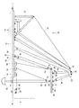
도 1은 본 발명에 따른 실시 예로서, 풍력타워 설치용 해상 크레인을 나타낸 측면도이다.
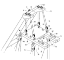
도 2는 본 발명에 따른 풍력타워 설치용 해상 크레인에서 붐과 리프팅 포크 및 바지 위의 주요 부분을 나타낸 사시도이다.
도 3은 본 발명에 따른 풍력타워 설치용 해상 크레인에서 붐과 리프팅 포크의 주요 부분을 나타낸 사시도이다.
도 4는 본 발명에 따른 풍력타워 설치용 해상 크레인에서 리프팅 포크의 분리사시도이다.
도 5는 본 발명에 따른 풍력타워 설치용 해상 크레인에서 리프팅 포크 전체의 평형을 유지하도록 하는 구성을 나타낸 도면이다.
도 6은 본 발명에 따른 풍력타워 설치용 해상 크레인에서 씨 앵커와 관련된 구성을 나타낸 도면이다.
도 7은 본 발명에 따른 풍력타워 설치용 해상 크레인에서 풍력타워가 좌우로 흔들리거나 회전하는 것을 방지하도록 하는 구성을 나타낸 도면이다.
도 8a 내지 도 8c는 본 발명에 따른 풍력타워 설치용 해상 크레인을 이용하여 해상에 풍력타워를 설치하는 과정을 나타낸 도면이다.FIG. 1 is a side view showing a marine crane for installing a wind tower as an embodiment according to the present invention.
Fig. 2 is a perspective view showing a main part on a boom, a lifting fork, and a pants in a marine cranes for installing a wind tower according to the present invention.
3 is a perspective view showing a main part of a boom and a lifting fork in a marine crane for installing a wind tower according to the present invention.
4 is an exploded perspective view of a lifting fork in a floating crane for installing a wind tower according to the present invention.
5 is a view showing a configuration for maintaining the balance of the entire lifting fork in a floating crane for installing a wind tower according to the present invention.
6 is a view showing a configuration related to a seed anchor in a marine crane for installing a wind tower according to the present invention.
7 is a view showing a configuration for preventing the wind tower from shaking or rotating from side to side in a floating crane for installing a wind tower according to the present invention.
8A to 8C are views showing a process of installing a wind tower on the sea using a marine crane for installing a wind tower according to the present invention.
이하, 본 발명의 실시 예에 따른 풍력타워 설치용 해상 크레인에 관하여 첨부된 도면을 참조하여 상세하게 설명하면 다음과 같다.Hereinafter, a floating crane for installing a wind tower according to an embodiment of the present invention will be described in detail with reference to the accompanying drawings.
도 1에서, 본 발명의 해상 크레인(10, 일명 'Forklift 해상 크레인')은 바지(Barge)(11) 위에 윈치(Winch)(12)와 백트레이(Back Tray)(13)를 거쳐 붐(Boom)(20)이 와이어로프(Wire Rope)(14)로 지지 및 승강되는 구조로 이루어져 있다. 본 발명의 해상 크레인(10)은 육상에서 조립된 풍력타워(2)를 해상에 이미 설치된 기초구조물 위에 보다 용이하게 설치하기 위한 구조를 갖는다.1, a marine crane 10 (also known as a " forklift marine crane ") of the present invention includes a
또한, 일정 길이를 갖는 붐(20)은 하단부가 바지(11) 표면에 힌지 결합된다. 붐(20) 상단부에는 제1풀리(15)가 고정 설치된다. 붐(20)의 제1풀리(15)는 와이어로프(14)로 윈치(12)와 백트레이(13) 및 바지(11)에 설치된 복수의 풀리 등과 연결된다. 따라서 붐(20)은 윈치(12)의 작동에 의하여 하단부의 힌지축을 중심으로 일정 각도의 기울기로 승강된다.The lower end of the
도 1 내지 도 3에 도시된 바와 같이, 본 발명의 해상 크레인(10)에서 지지대(21)는 붐(20) 상단부에 일정 각도로 경사각이 형성된 것이다. 지지대(21) 내측으로 홈(22)이 형성되어 있다. 지지대(21) 상단 양측에는 각각 한 쌍의 제2풀리(23)가 고정 설치되어 있고, 제2풀리(23)는 윈치(12)와 와이어로프(24)로 연결된다. 또한, 각 와이어로프(24)에는 제3풀리(25)가 결합되어 있다. 제3풀리(25)는 와이어로프(24)의 당김과 풀림에 따라 승강된다. 제3풀리(25)에는 각각 후크(26)가 결합되어 있다. 제2풀리(23)가 결합된 지지대(21)에는 상하로 관통공이 형성되어 와이어로프(24)가 관통 연결된다. 상기 제2풀리(23), 와이어로프(24), 제3풀리(25) 및 후크(26)는 리프팅 포크(27)를 지지하는 지지부재이다.1 to 3, in the
도 2 및 도 5에 도시된 바와 같이, 본 발명의 해상 크레인(10)에서 리프팅 포크(Lifting Fork)(27)는 대략 평판형상으로, 리프팅 포크(27)의 일측에는 복수의 고정편(40)이 구비되어 있고 바지(11) 표면에도 복수의 고정편(41)과 윈치(50)가 구비되어 있으며, 상기 고정편(40,41)에는 각각 후크(60)가 결합되고 상기 후크(60)에는 각각 제4풀리(70)가 결합되는데, 와이어로프(80)는 상기 윈치(50)와 제4풀리(70)를 거치면서 결합되어 있어 상기 윈치(50)의 작동에 의해 와이어로프(80)의 당김과 풀림에 따라 리프팅 포크(27)의 일측은 승하강하게 된다. 이는 후술하는 리프팅 포크(27) 타측에서 핀홈(28)에 풍력타워의 무게 중심부에 돌출된 핀러그(8)가 안착될 때 그 외력에 대한 저항력으로 작용하게 하여 리프팅 포크(27) 전체의 평형을 유지시켜주기 위함이다.2 and 5, the
그리고 도 2 내지 도 4에 도시된 바와 같이, 리프팅 포크(27) 타측에는 풍력타워가 삽입되어 지지되는 홀더(Holder)(29)가 형성된다. 홀더(29) 내측면은 정방형이거나 원호형으로 형성되는 것이 좋다. 홀더(29) 표면에는 풍력타워의 무게 중심부에 돌출된 핀러그(Pin Lug)(8)가 안착되는 핀홈(28)이 형성되어 있다. 여기서, 핀러그(8)가 구비된 풍력타워가 리프팅 포크(27)의 핀홈(28)에 안착됨으로써 풍력타워의 무게중심으로부터 넛셀, 허브 및 블레이드 등으로 구성된 풍력발전기의 기계장치까지는 리프팅 포크(27)의 상부에 위치하므로 풍력타워의 전체 높이를 그만큼 더 고도화시킬 수 있는 것이다. 핀러그(8)는 한 쌍으로 원기둥 또는 반원기둥 형상이고, 핀홈(28)은 핀러그(8)에 대응되도록 원호형으로 형성된다. 또한, 다양한 크기의 풍력타워를 리프팅시키기 위해 상기 홀더(29) 내측면의 폭을 핀러그(Pin Lug)(8) 위치의 풍력타워 직경에 대응시킬 필요가 있는데, 이를 위해 상면에는 핀홈(28')이 형성되어 있고 측면에는 홀더(29) 내측면 홈(22')에 끼움결합되는 돌출부(91)가 형성된 막대 형상의 홀더 폭 조절부재(90)가 고정구(미도시)로 홀더 내측면 일측 또는 양측에 고정시킬 수 있다.As shown in FIGS. 2 to 4, a
핀러그(8)는 풍력타워 몸체에 형성된 통공에 고정되거나 별도의 핀러그를 풍력타워 몸체에 고정시키기 위한 부재가 결합될 수 있을 것이다. 또한, 리프팅 포크(27) 표면에는 복수의 고정고리(16)가 돌출 형성되어 있다. 고정고리(16)에는 제3풀리(25)의 후크(26)가 결합된다. 즉 리프팅 포크(27) 표면 좌측과 우측에 각각 복수 개씩 결합된다. 여기서, 상기 제3풀리(25)의 후크(26)가 결합되는 고정고리(16)는 풍력타워의 하중이나 해상 크레인의 크기에 따라 상기 복수의 고정고리(16) 중에서 선택된다. The pin lugs 8 may be fixed to the through holes formed in the wind tower body or members for fixing separate pin lugs to the wind tower body. Further, a plurality of fixing rings 16 protrude from the surface of the lifting
그러므로 본 발명의 해상 크레인(10)의 붐(20)에는 윈치(12)와 연결된 와이어로프(14)의 당김과 풀림에 따라 붐의 각도를 조절하는 제1풀리(15)와, 붐(20)에는 윈치(12)와 연결된 와이어로프(24)의 당김과 풀림에 따라 리프팅 포크(27)를 승강시킬 수 있도록 하는 최소 4개씩의 제2풀리(23) 및 제3풀리(25)가 결합된다.The
다시 말해, 제2풀리(23) 및 제3풀리(25)는 리프팅 포크(27) 전체를 승하강시키기 위한 것이고 제4풀리(70)는 리프팅 포크(27)의 일측만 승하강시켜 리프팅 포크(27) 전체의 평형을 유지시키기 위한 것이다.In other words, the
또한, 도 2 및 도 6에 도시된 바와 같이, 리프팅 포크(27)가 좌우로 흔들리는 것을 방지하기 위해 수중저항이 큰 씨 앵커(sea anchor)(61) 1개 또는 2개를 리프팅 포크(27)에 매달게 되는데, 씨 앵커(sea anchor)(61)가 1개일 때는 리프팅 포크(27)의 저면 중앙에, 씨 앵커(sea anchor)(61)가 2개일 때는 리프팅 포크(27)의 양측에 고정편(42)이 구비되어 있고 바지(11) 표면에 윈치(51)가 구비되어 있으며, 상기 고정편(42)에는 후크(62)가 결합되고 상기 후크(62)에는 제5풀리(71)가 결합되고 수중의 씨 앵커(sea anchor)(61)는 또 다른 제5풀리(71)에 결합되는데, 와이어로프(81)는 상기 윈치(51)와 제5풀리(71)를 거치면서 결합되어 있어 상기 윈치(51)의 작동에 의해 와이어로프(81)의 당김과 풀림에 따라 씨 앵커(sea anchor)(61)는 승하강하게 된다. 여기서, 씨 앵커(61)는 호퍼(hopper)형태가 바람직하다.2 and 6, one or two
더불어, 도 2 및 도 7에 도시된 바와 같이, 본 발명의 해상 크레인(10)이 리프팅 포크(27)에 의해 풍력타워(2)를 리프팅시켜 기초구조물(1) 위에 풍력타워(2)를 설치할 때 풍력타워가 좌우로 흔들리거나 회전하는 것을 방지하기 위해, 풍력타워의 몸체 양측에는 복수의 고정고리(16')가 상하 일정간격으로 구비되어 있고 바지(11) 표면에는 윈치(52)가 1개 내지 2개 구비되어 있으며, 풍력타워 몸체 일측 또는 양측의 고정고리(16') 중 1개 내지 2개에는 후크(63)가 결합되고 상기 후크(63)에는 제6풀리(72)가 결합되는데, 와이어로프(82)는 상기 윈치(52)와 제6풀리(72)를 거치면서 결합되어 있어 풍력타워의 높낮이에 대응하여 상기 윈치(52)의 작동에 의해 와이어로프(82)의 당김과 풀림에 따라 와이어로프(82)의 텐션을 유지시켜 풍력타워가 좌우로 흔들리거나 회전하는 것을 방지할 수 있다.2 and 7, the floating
한편, 리프팅 포크(27)에는 전자식 수평계가 부착되어 있어서 풍력타워(2)를 리프팅할 때 평형을 확인할 수 있도록 함이 바람직하다.
On the other hand, the lifting
이와 같이 이루어진 본 발명에 따른 풍력타워 설치용 해상 크레인을 이용하여 풍력타워를 설치하는 방법에 관하여 도 8을 참조하여 설명한다.A method of installing a wind tower using a floating crane for installing a wind tower according to the present invention will be described with reference to FIG.
육상에서 풍력타워의 주요 구성인 복수 단의 타워(Tower), 넛셀(Nutshell), 허브(Hub) 및 블레이드(Blade)를 일체 조립한다(S10). 조립이 완료된 풍력타워를 육상에 설치된 대형 크레인으로 끌어 올려 기립시킨다(S20).A multi-stage tower, a nutshell, a hub, and a blade, which are major components of a wind tower, are assembled together on a land (S10). The assembled wind turbine tower is lifted up by a large crane mounted on the ground to rise (S20).
상기 육상 크레인으로 조립이 완료된 풍력타워를 운송용 바지선(30) 위에 올려놓고 복수의 고정용 와이어(31) 등을 이용하여 고정시켜 선적한다(S30). 이때, 운송용 바지선(30) 표면에 플랜지부가 설치되어 있어 풍력타워의 저부에 형성된 플랜지를 고정부재 등으로 결합하는 것이 좋다. 그리고 조립이 완료된 풍력타워가 고정 선적된 운송용 바지선(30)을 예인선으로 예인하여 조립이 완료된 풍력타워를 설치할 위치에 있는 본 발명의 해상 크레인(10)까지 이동시킨다(S40).The assembled wind turbine tower is mounted on the
이는 도 8a에서, 운송용 바지선(30)을 본 발명의 해상 크레인(10)과 근접하는 위치까지 이동시키는 것이다.8A, the
본 발명의 해상 크레인(10)은 운송용 바지선(30)에 고정된 풍력타워를 분리시킨다(S50). 즉 운송용 바지선(30)에서 조립된 풍력타워를 리프팅하는 세부적인 흐름은 다음과 같다.The
본 발명의 해상 크레인(10)을 운송용 바지선(30)에 선적된 풍력타워 쪽으로 이동시킨 후에 윈치(12)의 작동으로 해상 크레인(10)의 붐(20)을 상승 또는 하강시킨다(S51). 이때, 붐(20) 상부의 리프팅 포크(27)를 조립이 완료된 풍력타워의 무게 중심부에 결합된 핀러그(8) 아래로 위치시킨 후(S52), 조립이 완료된 풍력타워 몸체가 리프팅 포크(27)의 홀더(29)에 삽입되도록 하고, 풍력타워 몸체의 고정고리(16')에 후크(63)를 결합시켜 윈치(52)의 작동에 의해 와이어로프(82)의 당김과 풀림에 따라 와이어로프(82)의 텐션을 유지시켜 풍력타워가 좌우로 흔들리거나 회전하는 것을 방지할 수 있도록 한다(S53). 이 때 사전에 인지된 풍력타워의 직경에 홀더(29) 내측면의 폭을 대응시키기 위해 홀더 폭 조절부재(90)가 홀더 내측면 일측 또는 양측에 미리 고정되어 있고, 리프팅 포크(27)가 좌우로 흔들리는 것을 방지하기 위해 씨 앵커(sea anchor)(61) 1개 또는 2개가 리프팅 포크(27)에 미리 매달려 있을 수 있다.The
그리고 리프팅 포크(27)를 일정 높이로 상승시켜 조립이 완료된 풍력타워의 핀러그(8)가 홀더(29)의 핀홈(28)에 위치되도록 한 상태가 되도록 하고(S54), 운송용 바지선(30)에 고정된 플랜지 및 고정와이어(31)를 각각 분리시킨다(S55). 또한, 붐(20)을 일정 높이로 상승시켜 조립이 완료된 풍력타워가 운송용 바지선(30)으로부터 완전히 분리되도록 함과 동시에, 윈치(50)의 작동에 의해 와이어로프(80)의 당김과 풀림에 따라 리프팅 포크(27)의 일측을 승하강하게 하면서 리프팅 포크(27) 타측에서 핀홈(28)에 풍력타워의 핀러그(8)가 안착될 때 그 외력에 대한 저항력으로 작용하게 하여 리프팅 포크(27) 전체의 평형을 유지시켜주게 하고(S56), 운송용 바지선(30)이 후퇴되도록 한다(S57). The lifting
이는 도 8b에서, 본 발명의 해상 크레인(10)의 붐(20)과 리프팅 포크(27)에 의해 조립이 완료된 풍력타워를 리프팅시켜 지지하는 상태가 된다.8B, the
한편, 본 발명의 해상 크레인(10)으로 해상에 이미 설치된 기초구조물(1) 위에 조립이 완료된 풍력타워를 위치시켜 고정시킨다(S60). 즉 해상 크레인(10)이 리프팅시킨 풍력타워를 기초구조물에 위치시키는 세부적인 흐름은 다음과 같다.On the other hand, the assembled wind turbine tower is positioned and fixed on the foundation structure 1 already installed on the sea with the
조립이 완료된 풍력타워를 리프팅시켜 지지하고 있는 본 발명의 해상 크레인(10)을 이동시켜 이미 설치된 기초구조물, 즉 도 8c에서, 본 발명의 해상 크레인(10)이 조립이 완료된 풍력타워를 설치할 위치에는 기초구조물이 설치되어 있어야 하고, 이 기초구조물(1) 위에 본 발명의 해상 크레인(10)의 붐(20)이 위치되도록 한다(S61). 이때, 윈치(12,50)를 작동시켜 와이어로프(14,24,80)을 풀거나 당겨 붐(20)의 높이와 리프팅 포크(27)의 높이와 평형이 미세하게 조절되도록 해야 할 것이다.In the already installed foundation structure, that is, the foundation structure in which the
본 발명의 해상 크레인(10)으로 기초구조물(1) 상단면에 구비된 플랜지 위에 조립이 완료된 풍력타워의 플랜지(4)를 일치시킨 후에 기초구조물(1)에 풍력타워를 고정부재 등으로 결합하여 고정시킨다(S62). 이 때, 핀홈(28)에 풍력타워의 핀러그(8)가 안착될 때의 외력이 없어지게 되므로 윈치(50)의 작동에 의해 와이어로프(80)의 당김 또는 풀림에 의해 와이어로프(80)를 느슨하게 하고 풍력타워 몸체의 고정고리(16')에서 후크(63)를 분리시킨다.After the
조립이 완료된 풍력타워가 기초구조물(1) 위에 고정되면 해상 크레인(10)의 붐(20)을 하강시키고(S63), 해상 크레인(10)의 붐(20)을 후퇴시킨다(S64). 이로서 풍력타워의 육상 조립, 해상 이송 및 설치가 완료된다.
When the assembled wind turbine tower is fixed on the foundation structure 1, the
이상의 설명에서 본 발명은 특정의 실시 예와 관련하여 도시 및 설명하였지만, 특허청구범위에 의해 나타난 발명의 사상 및 영역으로부터 벗어나지 않는 한도 내에서 다양한 개조 및 변화가 가능하다는 것을 이 기술분야에서 통상의 지식을 가진 자라면 누구나 쉽게 알 수 있을 것이다.
While the invention has been shown and described with respect to the specific embodiments thereof, it will be understood by those skilled in the art that various changes and modifications may be made without departing from the spirit and scope of the invention as defined by the appended claims. Anyone who has it will know it easily.
1: 기초구조물 2: 풍력타워 3: 타워 4: 플랜지 5: 넛셀 6: 허브 7: 블레이드 8: 핀러그 10: 해상 크레인 11: 바지 12,50,51,52: 윈치 13: 백트레이 14,24,80,81,82: 와이어로프 15,23,25,70,71,72: 풀리 16,16': 고정고리 20: 붐 21: 지지대 22,22': 홈 26,60,62,63: 후크 27: 리프팅 포크 28,28': 핀홈 29: 홀더 30: 운송용 바지선 31: 고정용 와이어 40,41,42: 고정편 61: 씨 앵커 90: 홀더 폭 조절부재 91: 돌출부1: Foundation structure 2: Wind tower 3: Tower 4: Flange 5: Nacelle 6: Hub 7: Blade 8: Pin lug 10: Marine crane 11:
Claims (7)
상기 붐(20) 상단부에 일정 각도로 경사각이 형성된 지지대(21);
평판형상으로 일측에 복수의 고정편(40)이 구비되어 있고 타측에 풍력타워가 삽입 지지되는 홀더(29)가 형성되며, 홀더(29) 표면에 풍력타워의 무게 중심부에 돌출된 핀러그(8)가 안착되는 핀홈(28)이 형성되고, 표면에 복수의 고정고리(16)가 구비되어 풍력타워를 리프팅시켜 지지하는 리프팅 포크(27);
상기 지지대(21) 상단 양측에 각각 고정 설치되어 윈치(12)와 와이어로프(24)로 연결된 한 쌍의 제2풀리(23)가 구비되고, 상기 제2풀리(23)를 거쳐 와이어로프(24)가 연결되고 와이어로프(24)의 당김과 풀림에 따라 승강되는 제3풀리(25)가 구비되며, 상기 제3풀리(25)에 리프팅 포크(27) 표면에 돌출된 상기 고정고리(16)에 결합되는 후크(26)가 구비된, 리프팅 포크의 지지부재를 포함하고,
바지(11) 표면에 복수의 고정편(41)과 윈치(50)가 구비되어 있고, 상기 고정편(40,41)에는 각각 후크(60)가 결합되고 상기 후크(60)에는 각각 제4풀리(70)가 결합되며, 와이어로프(80)는 상기 윈치(50)와 제4풀리(70)를 거치면서 결합되어 있어 상기 윈치(50)의 작동에 의해 와이어로프(80)의 당김과 풀림에 따라 리프팅 포크(27)의 일측은 승하강하게 됨으로써, 리프팅 포크(27) 타측에서 핀홈(28)에 풍력타워의 핀러그(8)가 안착될 때 그 외력에 대한 저항력으로 작용하게 하여 리프팅 포크(27) 전체의 평형을 유지하도록 구성되는 것을 특징으로 하는 풍력타워 설치용 해상 크레인.
A boom 20 having a predetermined length to which a winch 12 and a wire rope 14 are connected from a back tray 13 to a first pulley 15 hinged to the surface of the pants 11 at a lower end and installed at an upper end;
A support table 21 formed at an upper end of the boom 20 and having an inclination angle at a predetermined angle;
A plurality of fixing pieces 40 are provided on one side of the flat plate and a holder 29 is formed on the other side of the holder 29 to receive and support the wind tower and a pin lug 8 projecting from the center of gravity of the wind tower A lifting fork 27 provided with a plurality of fixing rings 16 on the surface thereof for lifting and supporting the wind tower;
And a pair of second pulleys 23 connected to the winch 12 and the wire ropes 24 and fixed to both sides of the upper end of the support frame 21 via wire ropes 24 And the third pulley 25 is provided with the fixing ring 16 protruding from the surface of the lifting fork 27. The third pulley 25 is connected to the third pulley 25 by the wire rope 24, A support member of a lifting fork, provided with a hook (26)
A plurality of fastening pieces 41 and a winch 50 are provided on the surface of the pants 11 and hooks 60 are respectively engaged with the fastening pieces 40 and 41, And the wire rope 80 is coupled to the winch 50 through the fourth pulley 70 so that the wire rope 80 is pulled and loosened by the operation of the winch 50 One side of the lifting fork 27 is lifted and lowered to act as a resistance force against the external force when the pin lug 8 of the wind tower is seated in the pin groove 28 from the other side of the lifting fork 27, ) Of the wind turbine tower (1).
상기 홀더(29) 내측면의 폭을 핀러그(8) 위치의 풍력타워 직경에 대응시키기 위해 상면에는 핀홈(28')이 형성되어 있고 측면에는 홀더(29) 내측면 홈(22')에 끼움결합되는 돌출부(91)가 형성된 막대 형상의 홀더 폭 조절부재(90)가 추가로 구성되는 것을 특징으로 하는 풍력타워 설치용 해상 크레인.
The method according to claim 1,
A pin groove 28 'is formed on the upper surface of the holder 29 so as to correspond to the wind tower diameter at the position of the pin lug 8 and a side wall groove 22' Characterized in that a rod-shaped holder width adjusting member (90) with a protruding portion (91) to be joined is additionally constituted.
바지(11) 표면에 구비된 윈치(51);
리프팅 포크(27)의 저면 중앙 또는 리프팅 포크(27)의 양측에 구비된 고정편(42)을 추가로 포함하고,
상기 고정편(42)에는 후크(62)가 결합되고 상기 후크(62)에는 제5풀리(71)가 결합되고 수중의 씨 앵커(61)는 또 다른 제5풀리(71)에 결합되며, 와이어로프(81)는 상기 윈치(51)와 제5풀리(71)를 거치면서 결합되어 있어 상기 윈치(51)의 작동에 의해 와이어로프(81)의 당김과 풀림에 따라 씨 앵커(sea anchor)(61)는 승하강하게 됨으로써, 리프팅 포크(27)가 좌우로 흔들리는 것을 방지하도록 추가로 구성되는 것을 특징으로 하는 풍력타워 설치용 해상 크레인.
The method according to claim 1,
A winch 51 provided on the surface of the pants 11;
Further comprising a fixing piece (42) provided at the bottom center of the lifting fork (27) or on both sides of the lifting fork (27)
A hook 62 is coupled to the fixing piece 42 and a fifth pulley 71 is coupled to the hook 62. The seed anchor 61 in the water is coupled to another fifth pulley 71, The rope 81 is connected to the winch 51 through the fifth pulley 71 and is pulled and pulled by the operation of the winch 51 to form a sea anchor 61) is further raised and lowered to prevent the lifting fork (27) from swaying from side to side.
풍력타워의 몸체 양측에 상하 일정간격으로 구비되어 있는 복수의 고정고리(16');
바지(11) 표면에 구비된 윈치(52)를 추가로 포함하고,
풍력타워 몸체 일측 또는 양측의 고정고리(16') 중 일부에 후크(63)가 결합되고 상기 후크(63)에는 제6풀리(72)가 결합되며, 와이어로프(82)는 상기 윈치(52)와 제6풀리(72)를 거치면서 결합되어 있어 상기 윈치(52)의 작동에 의해 와이어로프(82)의 당김과 풀림에 따라 와이어로프(82)의 텐션을 유지시켜 풍력타워가 좌우로 흔들리거나 회전하는 것을 방지하도록 추가로 구성되는 것을 특징으로 하는 풍력타워 설치용 해상 크레인.
The method according to claim 1,
A plurality of fixing rings 16 'provided on both sides of the body of the wind tower at regular intervals in the vertical direction;
Further comprising a winch (52) provided on the surface of the pants (11)
A hook 63 is coupled to a part of the fixing ring 16 'on one side or both sides of the wind tower body and a sixth pulley 72 is coupled to the hook 63. The wire rope 82 is connected to the winch 52, So that the tension of the wire rope 82 is maintained by the pulling and unwinding of the wire rope 82 by the operation of the winch 52 and the wind tower is shaken to the left and right Wherein the crane is further configured to prevent rotation of the crane.
상기 홀더(29) 내측면은 정방형이거나 원호형으로 형성된 풍력타워 설치용 해상 크레인.
The method according to claim 1,
And the inner side surface of the holder (29) is square or arcuate.
상기 핀러그(8)는 원통 또는 반원통 형상이고, 핀홈(28)은 원호형으로 형성된 풍력타워 설치용 해상 크레인.
The method according to claim 1,
Wherein the pin lug (8) has a cylindrical or semicylindrical shape and the pin groove (28) has an arc shape.
상기 리프팅 포크(27)에는 풍력타워(2)를 리프팅할 때 평형을 확인할 수 있도록 하는 전자식 수평계가 추가로 부착되어 있는 풍력타워 설치용 해상 크레인.
The method according to claim 1,
Wherein the lifting fork (27) is further provided with an electronic leveling device for checking the balance when lifting the wind tower (2).
Priority Applications (1)
| Application Number | Priority Date | Filing Date | Title |
|---|---|---|---|
| KR1020150019301A KR101657224B1 (en) | 2015-02-09 | 2015-02-09 | Floating Crane for Installation Offshore Wind Tower |
Applications Claiming Priority (1)
| Application Number | Priority Date | Filing Date | Title |
|---|---|---|---|
| KR1020150019301A KR101657224B1 (en) | 2015-02-09 | 2015-02-09 | Floating Crane for Installation Offshore Wind Tower |
Publications (2)
| Publication Number | Publication Date |
|---|---|
| KR20160097529A true KR20160097529A (en) | 2016-08-18 |
| KR101657224B1 KR101657224B1 (en) | 2016-09-13 |
Family
ID=56874059
Family Applications (1)
| Application Number | Title | Priority Date | Filing Date |
|---|---|---|---|
| KR1020150019301A KR101657224B1 (en) | 2015-02-09 | 2015-02-09 | Floating Crane for Installation Offshore Wind Tower |
Country Status (1)
| Country | Link |
|---|---|
| KR (1) | KR101657224B1 (en) |
Cited By (6)
| Publication number | Priority date | Publication date | Assignee | Title |
|---|---|---|---|---|
| CN107651115A (en) * | 2017-10-26 | 2018-02-02 | 南通欣通船舶与海洋工程设计有限公司 | Water self-tipping type anti-rotation device under a kind of offshore wind turbine |
| CN108466957A (en) * | 2018-03-30 | 2018-08-31 | 南通振华重型装备制造有限公司 | A kind of 2000t crane barges crane main hook steel wire rope surplus blocks technique |
| CN110709602A (en) * | 2017-06-12 | 2020-01-17 | 西门子歌美飒可再生能源公司 | Offshore wind turbine installation |
| KR20200107105A (en) * | 2019-03-06 | 2020-09-16 | 유한회사 티오씨 | Floating crane for installation of offshore wind turbine tower using the movable counter weight |
| CN114933255A (en) * | 2022-05-13 | 2022-08-23 | 海洋石油工程股份有限公司 | Integral lifting and mounting method for offshore wind turbine |
| KR20230139204A (en) * | 2022-03-25 | 2023-10-05 | 이한구 | launch and recovery apparatus for spa buoy |
Citations (5)
| Publication number | Priority date | Publication date | Assignee | Title |
|---|---|---|---|---|
| JPS6223284U (en) * | 1985-07-25 | 1987-02-12 | ||
| JP2008128252A (en) * | 2006-11-23 | 2008-06-05 | Siemens Ag | Method and device for mounting wind turbine blade |
| KR20100045404A (en) | 2008-08-28 | 2010-05-03 | 미츠비시 쥬고교 가부시키가이샤 | Method and device for constructing marine wind power generation device |
| KR20140056415A (en) * | 2012-10-25 | 2014-05-12 | 삼성중공업 주식회사 | Crane |
| KR20140118470A (en) * | 2013-03-29 | 2014-10-08 | 곽대진 | Floating Crane and Method for Installation Offshore Wind Tower |
-
2015
- 2015-02-09 KR KR1020150019301A patent/KR101657224B1/en active IP Right Grant
Patent Citations (5)
| Publication number | Priority date | Publication date | Assignee | Title |
|---|---|---|---|---|
| JPS6223284U (en) * | 1985-07-25 | 1987-02-12 | ||
| JP2008128252A (en) * | 2006-11-23 | 2008-06-05 | Siemens Ag | Method and device for mounting wind turbine blade |
| KR20100045404A (en) | 2008-08-28 | 2010-05-03 | 미츠비시 쥬고교 가부시키가이샤 | Method and device for constructing marine wind power generation device |
| KR20140056415A (en) * | 2012-10-25 | 2014-05-12 | 삼성중공업 주식회사 | Crane |
| KR20140118470A (en) * | 2013-03-29 | 2014-10-08 | 곽대진 | Floating Crane and Method for Installation Offshore Wind Tower |
Cited By (10)
| Publication number | Priority date | Publication date | Assignee | Title |
|---|---|---|---|---|
| CN110709602A (en) * | 2017-06-12 | 2020-01-17 | 西门子歌美飒可再生能源公司 | Offshore wind turbine installation |
| US11198597B2 (en) | 2017-06-12 | 2021-12-14 | Siemens Gamesa Renewable Energy A/S | Sensing arrangement for stabilizing an offshore wind turbine installation arrangement |
| CN110709602B (en) * | 2017-06-12 | 2022-04-15 | 西门子歌美飒可再生能源公司 | Offshore wind turbine installation |
| CN107651115A (en) * | 2017-10-26 | 2018-02-02 | 南通欣通船舶与海洋工程设计有限公司 | Water self-tipping type anti-rotation device under a kind of offshore wind turbine |
| CN107651115B (en) * | 2017-10-26 | 2024-06-25 | 南通欣通船舶与海洋工程设计有限公司 | Self-discharging type anti-rotation device for offshore wind turbine launching |
| CN108466957A (en) * | 2018-03-30 | 2018-08-31 | 南通振华重型装备制造有限公司 | A kind of 2000t crane barges crane main hook steel wire rope surplus blocks technique |
| KR20200107105A (en) * | 2019-03-06 | 2020-09-16 | 유한회사 티오씨 | Floating crane for installation of offshore wind turbine tower using the movable counter weight |
| KR20230139204A (en) * | 2022-03-25 | 2023-10-05 | 이한구 | launch and recovery apparatus for spa buoy |
| CN114933255A (en) * | 2022-05-13 | 2022-08-23 | 海洋石油工程股份有限公司 | Integral lifting and mounting method for offshore wind turbine |
| CN114933255B (en) * | 2022-05-13 | 2024-05-17 | 海洋石油工程股份有限公司 | Integral lifting installation method for offshore wind turbine |
Also Published As
| Publication number | Publication date |
|---|---|
| KR101657224B1 (en) | 2016-09-13 |
Similar Documents
| Publication | Publication Date | Title |
|---|---|---|
| KR101657224B1 (en) | Floating Crane for Installation Offshore Wind Tower | |
| JP6835594B2 (en) | Floating structure and installation method of floating structure | |
| JP6039097B2 (en) | Floating transport and installation structure, and floating wind turbine | |
| US8118538B2 (en) | Offshore vertical-axis wind turbine and associated systems and methods | |
| KR101790970B1 (en) | Method for installation of offshore wind power generator assembled on land | |
| US8657534B2 (en) | Floating platform with improved anchoring | |
| JP5670128B2 (en) | Floating structure for offshore facilities and construction method of offshore facilities | |
| JP5274329B2 (en) | Offshore wind power generation facility and its construction method | |
| KR101240722B1 (en) | Sea Floating Wind Turbine Apparatus for Generating Electricity with a Floating Support Line Compressed Structure | |
| US20080240864A1 (en) | Assembly, transportation and installation of deepwater windpower plant | |
| KR102182302B1 (en) | Floating crane for installation of offshore wind turbine tower using the movable counter weight | |
| JP2011102587A (en) | Power generation assembly | |
| KR101774008B1 (en) | Mooring construction device of maritime photovoltaic power generation equipment | |
| WO2014163501A1 (en) | Floating wind turbine | |
| KR101484121B1 (en) | Floating Crane for Installation Offshore Wind Tower | |
| KR101262089B1 (en) | Sea establishment method of weather tower and wind turbine generator | |
| KR101202156B1 (en) | Floating windgenerator | |
| KR20120038708A (en) | Floating offshore wind power generation plant | |
| CN104100455B (en) | Floating type marine anemometer tower structure | |
| KR101201476B1 (en) | Floating offshore wind power generation plant | |
| JP7313212B2 (en) | Floating structures for offshore facilities and their installation structures | |
| KR102062204B1 (en) | Method for All-in-one Installation and Transportation of Offshore Wind Turbine | |
| KR100990128B1 (en) | A tide generation of electricity | |
| JP6063358B2 (en) | Ocean current power generator | |
| JP7492283B1 (en) | Method for constructing bottom-fixed offshore mounting system, bottom-fixed offshore mounting system, and offshore wind power generation device |
Legal Events
| Date | Code | Title | Description |
|---|---|---|---|
| A201 | Request for examination | ||
| E902 | Notification of reason for refusal | ||
| E701 | Decision to grant or registration of patent right | ||
| GRNT | Written decision to grant | ||
| FPAY | Annual fee payment |
Payment date: 20190625 Year of fee payment: 4 |