KR20160096639A - System and method to avoid magnetic power loss while providing alternating current through a ferromagnetic material - Google Patents
System and method to avoid magnetic power loss while providing alternating current through a ferromagnetic material Download PDFInfo
- Publication number
- KR20160096639A KR20160096639A KR1020167017630A KR20167017630A KR20160096639A KR 20160096639 A KR20160096639 A KR 20160096639A KR 1020167017630 A KR1020167017630 A KR 1020167017630A KR 20167017630 A KR20167017630 A KR 20167017630A KR 20160096639 A KR20160096639 A KR 20160096639A
- Authority
- KR
- South Korea
- Prior art keywords
- ferromagnetic material
- orifice
- region
- electrical conduit
- electrical
- Prior art date
Links
- 239000003302 ferromagnetic material Substances 0.000 title claims abstract description 178
- 230000005291 magnetic effect Effects 0.000 title claims abstract description 57
- 238000000034 method Methods 0.000 title claims abstract description 53
- 230000004907 flux Effects 0.000 claims abstract description 80
- 230000005540 biological transmission Effects 0.000 claims description 57
- 230000008878 coupling Effects 0.000 claims description 26
- 238000010168 coupling process Methods 0.000 claims description 26
- 238000005859 coupling reaction Methods 0.000 claims description 26
- 239000000463 material Substances 0.000 claims description 21
- 238000012546 transfer Methods 0.000 claims description 20
- 230000005465 channeling Effects 0.000 claims description 19
- 238000004519 manufacturing process Methods 0.000 claims description 5
- 238000005520 cutting process Methods 0.000 claims description 3
- 230000006698 induction Effects 0.000 description 133
- 229910000859 α-Fe Inorganic materials 0.000 description 39
- 238000004891 communication Methods 0.000 description 20
- 238000010586 diagram Methods 0.000 description 12
- 239000000306 component Substances 0.000 description 10
- 230000008901 benefit Effects 0.000 description 8
- 239000003990 capacitor Substances 0.000 description 8
- 238000003860 storage Methods 0.000 description 7
- 239000004020 conductor Substances 0.000 description 6
- 230000005672 electromagnetic field Effects 0.000 description 6
- 238000004088 simulation Methods 0.000 description 6
- 238000006243 chemical reaction Methods 0.000 description 5
- 239000004033 plastic Substances 0.000 description 5
- 229920003023 plastic Polymers 0.000 description 5
- 230000005294 ferromagnetic effect Effects 0.000 description 4
- 230000006870 function Effects 0.000 description 4
- 230000001939 inductive effect Effects 0.000 description 4
- 230000004048 modification Effects 0.000 description 4
- 238000012986 modification Methods 0.000 description 4
- 230000009467 reduction Effects 0.000 description 4
- 238000013461 design Methods 0.000 description 3
- 238000001514 detection method Methods 0.000 description 3
- 238000009826 distribution Methods 0.000 description 3
- 238000004146 energy storage Methods 0.000 description 3
- 230000033001 locomotion Effects 0.000 description 3
- 230000002093 peripheral effect Effects 0.000 description 3
- 230000000903 blocking effect Effects 0.000 description 2
- 238000004422 calculation algorithm Methods 0.000 description 2
- 230000008859 change Effects 0.000 description 2
- 239000008358 core component Substances 0.000 description 2
- 230000005611 electricity Effects 0.000 description 2
- 229910052751 metal Inorganic materials 0.000 description 2
- 239000002184 metal Substances 0.000 description 2
- 230000003287 optical effect Effects 0.000 description 2
- 239000002245 particle Substances 0.000 description 2
- 230000001902 propagating effect Effects 0.000 description 2
- 239000011241 protective layer Substances 0.000 description 2
- 230000004044 response Effects 0.000 description 2
- 238000000926 separation method Methods 0.000 description 2
- 230000011664 signaling Effects 0.000 description 2
- 239000011343 solid material Substances 0.000 description 2
- 238000001228 spectrum Methods 0.000 description 2
- 230000000007 visual effect Effects 0.000 description 2
- RYGMFSIKBFXOCR-UHFFFAOYSA-N Copper Chemical compound [Cu] RYGMFSIKBFXOCR-UHFFFAOYSA-N 0.000 description 1
- 108091029480 NONCODE Proteins 0.000 description 1
- 101710137710 Thioesterase 1/protease 1/lysophospholipase L1 Proteins 0.000 description 1
- 229910045601 alloy Inorganic materials 0.000 description 1
- 239000000956 alloy Substances 0.000 description 1
- 230000003321 amplification Effects 0.000 description 1
- 238000013459 approach Methods 0.000 description 1
- 230000000386 athletic effect Effects 0.000 description 1
- 230000006399 behavior Effects 0.000 description 1
- 238000004364 calculation method Methods 0.000 description 1
- 230000001413 cellular effect Effects 0.000 description 1
- 239000000919 ceramic Substances 0.000 description 1
- 238000002485 combustion reaction Methods 0.000 description 1
- 239000002131 composite material Substances 0.000 description 1
- 229910052802 copper Inorganic materials 0.000 description 1
- 239000010949 copper Substances 0.000 description 1
- 230000001419 dependent effect Effects 0.000 description 1
- 238000011161 development Methods 0.000 description 1
- 238000007599 discharging Methods 0.000 description 1
- 230000005684 electric field Effects 0.000 description 1
- 230000005674 electromagnetic induction Effects 0.000 description 1
- 230000007613 environmental effect Effects 0.000 description 1
- 230000007717 exclusion Effects 0.000 description 1
- 230000008713 feedback mechanism Effects 0.000 description 1
- 239000000945 filler Substances 0.000 description 1
- 230000017525 heat dissipation Effects 0.000 description 1
- 230000001976 improved effect Effects 0.000 description 1
- 230000001788 irregular Effects 0.000 description 1
- 238000002955 isolation Methods 0.000 description 1
- 239000010410 layer Substances 0.000 description 1
- 238000003754 machining Methods 0.000 description 1
- 238000012423 maintenance Methods 0.000 description 1
- 230000007246 mechanism Effects 0.000 description 1
- 150000002739 metals Chemical class 0.000 description 1
- 238000012544 monitoring process Methods 0.000 description 1
- 238000003199 nucleic acid amplification method Methods 0.000 description 1
- 230000003647 oxidation Effects 0.000 description 1
- 238000007254 oxidation reaction Methods 0.000 description 1
- 230000000149 penetrating effect Effects 0.000 description 1
- 230000035699 permeability Effects 0.000 description 1
- 230000010363 phase shift Effects 0.000 description 1
- 230000008092 positive effect Effects 0.000 description 1
- 230000000644 propagated effect Effects 0.000 description 1
- 230000001681 protective effect Effects 0.000 description 1
- 239000007787 solid Substances 0.000 description 1
- 230000000087 stabilizing effect Effects 0.000 description 1
- 239000000758 substrate Substances 0.000 description 1
- 230000008646 thermal stress Effects 0.000 description 1
- 230000001960 triggered effect Effects 0.000 description 1
- 238000002604 ultrasonography Methods 0.000 description 1
- XLYOFNOQVPJJNP-UHFFFAOYSA-N water Substances O XLYOFNOQVPJJNP-UHFFFAOYSA-N 0.000 description 1
Images


Classifications
-
- H—ELECTRICITY
- H02—GENERATION; CONVERSION OR DISTRIBUTION OF ELECTRIC POWER
- H02J—CIRCUIT ARRANGEMENTS OR SYSTEMS FOR SUPPLYING OR DISTRIBUTING ELECTRIC POWER; SYSTEMS FOR STORING ELECTRIC ENERGY
- H02J50/00—Circuit arrangements or systems for wireless supply or distribution of electric power
- H02J50/70—Circuit arrangements or systems for wireless supply or distribution of electric power involving the reduction of electric, magnetic or electromagnetic leakage fields
-
- B60L11/182—
-
- B60L11/1829—
-
- B—PERFORMING OPERATIONS; TRANSPORTING
- B60—VEHICLES IN GENERAL
- B60L—PROPULSION OF ELECTRICALLY-PROPELLED VEHICLES; SUPPLYING ELECTRIC POWER FOR AUXILIARY EQUIPMENT OF ELECTRICALLY-PROPELLED VEHICLES; ELECTRODYNAMIC BRAKE SYSTEMS FOR VEHICLES IN GENERAL; MAGNETIC SUSPENSION OR LEVITATION FOR VEHICLES; MONITORING OPERATING VARIABLES OF ELECTRICALLY-PROPELLED VEHICLES; ELECTRIC SAFETY DEVICES FOR ELECTRICALLY-PROPELLED VEHICLES
- B60L53/00—Methods of charging batteries, specially adapted for electric vehicles; Charging stations or on-board charging equipment therefor; Exchange of energy storage elements in electric vehicles
- B60L53/10—Methods of charging batteries, specially adapted for electric vehicles; Charging stations or on-board charging equipment therefor; Exchange of energy storage elements in electric vehicles characterised by the energy transfer between the charging station and the vehicle
- B60L53/12—Inductive energy transfer
- B60L53/122—Circuits or methods for driving the primary coil, e.g. supplying electric power to the coil
-
- B—PERFORMING OPERATIONS; TRANSPORTING
- B60—VEHICLES IN GENERAL
- B60L—PROPULSION OF ELECTRICALLY-PROPELLED VEHICLES; SUPPLYING ELECTRIC POWER FOR AUXILIARY EQUIPMENT OF ELECTRICALLY-PROPELLED VEHICLES; ELECTRODYNAMIC BRAKE SYSTEMS FOR VEHICLES IN GENERAL; MAGNETIC SUSPENSION OR LEVITATION FOR VEHICLES; MONITORING OPERATING VARIABLES OF ELECTRICALLY-PROPELLED VEHICLES; ELECTRIC SAFETY DEVICES FOR ELECTRICALLY-PROPELLED VEHICLES
- B60L53/00—Methods of charging batteries, specially adapted for electric vehicles; Charging stations or on-board charging equipment therefor; Exchange of energy storage elements in electric vehicles
- B60L53/30—Constructional details of charging stations
- B60L53/35—Means for automatic or assisted adjustment of the relative position of charging devices and vehicles
- B60L53/38—Means for automatic or assisted adjustment of the relative position of charging devices and vehicles specially adapted for charging by inductive energy transfer
-
- H—ELECTRICITY
- H01—ELECTRIC ELEMENTS
- H01F—MAGNETS; INDUCTANCES; TRANSFORMERS; SELECTION OF MATERIALS FOR THEIR MAGNETIC PROPERTIES
- H01F27/00—Details of transformers or inductances, in general
- H01F27/34—Special means for preventing or reducing unwanted electric or magnetic effects, e.g. no-load losses, reactive currents, harmonics, oscillations, leakage fields
-
- H—ELECTRICITY
- H01—ELECTRIC ELEMENTS
- H01F—MAGNETS; INDUCTANCES; TRANSFORMERS; SELECTION OF MATERIALS FOR THEIR MAGNETIC PROPERTIES
- H01F38/00—Adaptations of transformers or inductances for specific applications or functions
- H01F38/14—Inductive couplings
-
- H—ELECTRICITY
- H01—ELECTRIC ELEMENTS
- H01F—MAGNETS; INDUCTANCES; TRANSFORMERS; SELECTION OF MATERIALS FOR THEIR MAGNETIC PROPERTIES
- H01F41/00—Apparatus or processes specially adapted for manufacturing or assembling magnets, inductances or transformers; Apparatus or processes specially adapted for manufacturing materials characterised by their magnetic properties
- H01F41/02—Apparatus or processes specially adapted for manufacturing or assembling magnets, inductances or transformers; Apparatus or processes specially adapted for manufacturing materials characterised by their magnetic properties for manufacturing cores, coils, or magnets
-
- H02J5/005—
-
- H—ELECTRICITY
- H02—GENERATION; CONVERSION OR DISTRIBUTION OF ELECTRIC POWER
- H02J—CIRCUIT ARRANGEMENTS OR SYSTEMS FOR SUPPLYING OR DISTRIBUTING ELECTRIC POWER; SYSTEMS FOR STORING ELECTRIC ENERGY
- H02J50/00—Circuit arrangements or systems for wireless supply or distribution of electric power
- H02J50/10—Circuit arrangements or systems for wireless supply or distribution of electric power using inductive coupling
- H02J50/12—Circuit arrangements or systems for wireless supply or distribution of electric power using inductive coupling of the resonant type
-
- H—ELECTRICITY
- H02—GENERATION; CONVERSION OR DISTRIBUTION OF ELECTRIC POWER
- H02J—CIRCUIT ARRANGEMENTS OR SYSTEMS FOR SUPPLYING OR DISTRIBUTING ELECTRIC POWER; SYSTEMS FOR STORING ELECTRIC ENERGY
- H02J50/00—Circuit arrangements or systems for wireless supply or distribution of electric power
- H02J50/40—Circuit arrangements or systems for wireless supply or distribution of electric power using two or more transmitting or receiving devices
-
- H—ELECTRICITY
- H02—GENERATION; CONVERSION OR DISTRIBUTION OF ELECTRIC POWER
- H02J—CIRCUIT ARRANGEMENTS OR SYSTEMS FOR SUPPLYING OR DISTRIBUTING ELECTRIC POWER; SYSTEMS FOR STORING ELECTRIC ENERGY
- H02J50/00—Circuit arrangements or systems for wireless supply or distribution of electric power
- H02J50/60—Circuit arrangements or systems for wireless supply or distribution of electric power responsive to the presence of foreign objects, e.g. detection of living beings
-
- H—ELECTRICITY
- H02—GENERATION; CONVERSION OR DISTRIBUTION OF ELECTRIC POWER
- H02J—CIRCUIT ARRANGEMENTS OR SYSTEMS FOR SUPPLYING OR DISTRIBUTING ELECTRIC POWER; SYSTEMS FOR STORING ELECTRIC ENERGY
- H02J50/00—Circuit arrangements or systems for wireless supply or distribution of electric power
- H02J50/80—Circuit arrangements or systems for wireless supply or distribution of electric power involving the exchange of data, concerning supply or distribution of electric power, between transmitting devices and receiving devices
-
- H—ELECTRICITY
- H02—GENERATION; CONVERSION OR DISTRIBUTION OF ELECTRIC POWER
- H02J—CIRCUIT ARRANGEMENTS OR SYSTEMS FOR SUPPLYING OR DISTRIBUTING ELECTRIC POWER; SYSTEMS FOR STORING ELECTRIC ENERGY
- H02J50/00—Circuit arrangements or systems for wireless supply or distribution of electric power
- H02J50/90—Circuit arrangements or systems for wireless supply or distribution of electric power involving detection or optimisation of position, e.g. alignment
-
- H02J7/025—
-
- Y—GENERAL TAGGING OF NEW TECHNOLOGICAL DEVELOPMENTS; GENERAL TAGGING OF CROSS-SECTIONAL TECHNOLOGIES SPANNING OVER SEVERAL SECTIONS OF THE IPC; TECHNICAL SUBJECTS COVERED BY FORMER USPC CROSS-REFERENCE ART COLLECTIONS [XRACs] AND DIGESTS
- Y02—TECHNOLOGIES OR APPLICATIONS FOR MITIGATION OR ADAPTATION AGAINST CLIMATE CHANGE
- Y02T—CLIMATE CHANGE MITIGATION TECHNOLOGIES RELATED TO TRANSPORTATION
- Y02T10/00—Road transport of goods or passengers
- Y02T10/60—Other road transportation technologies with climate change mitigation effect
- Y02T10/70—Energy storage systems for electromobility, e.g. batteries
-
- Y—GENERAL TAGGING OF NEW TECHNOLOGICAL DEVELOPMENTS; GENERAL TAGGING OF CROSS-SECTIONAL TECHNOLOGIES SPANNING OVER SEVERAL SECTIONS OF THE IPC; TECHNICAL SUBJECTS COVERED BY FORMER USPC CROSS-REFERENCE ART COLLECTIONS [XRACs] AND DIGESTS
- Y02—TECHNOLOGIES OR APPLICATIONS FOR MITIGATION OR ADAPTATION AGAINST CLIMATE CHANGE
- Y02T—CLIMATE CHANGE MITIGATION TECHNOLOGIES RELATED TO TRANSPORTATION
- Y02T10/00—Road transport of goods or passengers
- Y02T10/60—Other road transportation technologies with climate change mitigation effect
- Y02T10/7072—Electromobility specific charging systems or methods for batteries, ultracapacitors, supercapacitors or double-layer capacitors
-
- Y—GENERAL TAGGING OF NEW TECHNOLOGICAL DEVELOPMENTS; GENERAL TAGGING OF CROSS-SECTIONAL TECHNOLOGIES SPANNING OVER SEVERAL SECTIONS OF THE IPC; TECHNICAL SUBJECTS COVERED BY FORMER USPC CROSS-REFERENCE ART COLLECTIONS [XRACs] AND DIGESTS
- Y02—TECHNOLOGIES OR APPLICATIONS FOR MITIGATION OR ADAPTATION AGAINST CLIMATE CHANGE
- Y02T—CLIMATE CHANGE MITIGATION TECHNOLOGIES RELATED TO TRANSPORTATION
- Y02T90/00—Enabling technologies or technologies with a potential or indirect contribution to GHG emissions mitigation
- Y02T90/10—Technologies relating to charging of electric vehicles
- Y02T90/12—Electric charging stations
-
- Y—GENERAL TAGGING OF NEW TECHNOLOGICAL DEVELOPMENTS; GENERAL TAGGING OF CROSS-SECTIONAL TECHNOLOGIES SPANNING OVER SEVERAL SECTIONS OF THE IPC; TECHNICAL SUBJECTS COVERED BY FORMER USPC CROSS-REFERENCE ART COLLECTIONS [XRACs] AND DIGESTS
- Y02—TECHNOLOGIES OR APPLICATIONS FOR MITIGATION OR ADAPTATION AGAINST CLIMATE CHANGE
- Y02T—CLIMATE CHANGE MITIGATION TECHNOLOGIES RELATED TO TRANSPORTATION
- Y02T90/00—Enabling technologies or technologies with a potential or indirect contribution to GHG emissions mitigation
- Y02T90/10—Technologies relating to charging of electric vehicles
- Y02T90/14—Plug-in electric vehicles
-
- Y—GENERAL TAGGING OF NEW TECHNOLOGICAL DEVELOPMENTS; GENERAL TAGGING OF CROSS-SECTIONAL TECHNOLOGIES SPANNING OVER SEVERAL SECTIONS OF THE IPC; TECHNICAL SUBJECTS COVERED BY FORMER USPC CROSS-REFERENCE ART COLLECTIONS [XRACs] AND DIGESTS
- Y10—TECHNICAL SUBJECTS COVERED BY FORMER USPC
- Y10T—TECHNICAL SUBJECTS COVERED BY FORMER US CLASSIFICATION
- Y10T29/00—Metal working
- Y10T29/49—Method of mechanical manufacture
- Y10T29/49002—Electrical device making
- Y10T29/4902—Electromagnet, transformer or inductor
- Y10T29/49075—Electromagnet, transformer or inductor including permanent magnet or core
Abstract
본 개시는 강자성 재료를 통해 교류를 제공하는 동안 자기 전력 손실을 회피시키기 위한 시스템, 방법 및 장치를 제공한다. 일 양태에서, 강자성 재료는 적어도 하나의 오리피스를 포함한다. 적어도 하나의 전기 도관은 강자성 재료의 제 1 측의 제 1 영역으로부터 강자성 재료의 제 2 측의 제 2 영역으로 적어도 하나의 오리피스를 통해 연장되고, 제 2 측은 제 1 측과 반대이다. 적어도 하나의 전기 도관은, 제 1 영역과 제 2 영역 사이에 적어도 하나의 전기 도관을 따라 흐르는 적어도 하나의 교류를 갖도록 구성된다. 강자성 재료 및 적어도 하나의 전기 도관은, 적어도 하나의 교류에 의해 강자성 재료 내에 생성된 주변 자속에 의해 야기되는 전력 손실을 감소시키도록 구성된다.The present disclosure provides a system, method and apparatus for avoiding magnetic power loss while providing alternating current through a ferromagnetic material. In an aspect, the ferromagnetic material comprises at least one orifice. The at least one electrical conduit extends from the first region of the first side of the ferromagnetic material to the second region of the second side of the ferromagnetic material through at least one orifice and the second side is opposite to the first side. The at least one electrical conduit is configured to have at least one alternating current flowing along at least one electrical conduit between the first region and the second region. The ferromagnetic material and the at least one electrical conduit are configured to reduce power loss caused by the ambient flux generated in the ferromagnetic material by at least one alternating current.
Description
본 개시는 일반적으로, 무선 전력 전송에 관한 것이고, 보다 상세하게는 배터리들을 포함하는 차량들 또는 전자 디바이스들과 같은 원격 시스템들에의 무선 전력 전송에 관련된 디바이스, 시스템 및 방법, 그리고 무선 전력 전송 시스템들에서 자기력 손실을 피하는 시스템 및 방법에 관한 것이다.This disclosure relates generally to wireless power transmission and more particularly to devices, systems and methods relating to wireless power transmission to remote systems, such as vehicles or electronic devices, including batteries, and wireless power transmission systems Lt; RTI ID = 0.0 > and / or < / RTI >
배터리 등의 에너지 저장 디바이스로부터 수신된 전기로부터 도출되는 운동력 (locomotion power) 을 포함하는, 차량들과 같은 원격 시스템들이 도입되어 있다. 예를 들어, 하이브리드 전기 차량들은, 차량 브레이킹 및 통상적인 모터들로부터의 전력을 이용하여 차량들을 충전하는 충전기들이 탑재되어 있다. 오로지 전기적인 차량들은 일반적으로, 다른 소스들로부터 배터리들을 충전하기 위해 전기를 수신한다. 배터리 전기 차량들 (전기 차량들) 은 종종, 일부 타입의 유선 교류 (AC), 이를테면 가정용 또는 상업용 AC 공급 소스들을 통하여 충전되는 것이 제안된다. 유선 충전 접속들은, 전력 공급부에 물리적으로 접속되는 케이블들 또는 다른 유사한 커넥터들을 필요로 한다. 케이블들 및 유사한 커넥터들은 때때로 불편하거나 또는 번거롭고 다른 단점들을 가질 수도 있다. 전기 차량들을 충전하기 위하여 사용될 전력을 자유 공간에서 (예를 들어, 무선 필드 (wireless field) 을 통해) 전송할 수 있는 무선 충전 시스템들은, 유선 충전 솔루션들의 결점들의 일부를 극복할 수도 있다. 그래서, 전기 차량들을 충전하기 위한 전력을 효율적으로 그리고 안전하게 전송하는 무선 충전 시스템들 및 방법들이 요망된다.Remote systems such as vehicles have been introduced that include locomotion power derived from electricity received from an energy storage device such as a battery. For example, hybrid electric vehicles are equipped with chargers that charge vehicles using vehicle braking and power from conventional motors. Only electrical vehicles typically receive electricity to charge batteries from other sources. Battery electric vehicles (electric vehicles) are often suggested to be charged through some type of wired alternating current (AC), such as household or commercial AC supply sources. Wired charging connections require cables or other similar connectors that are physically connected to the power supply. Cables and similar connectors are sometimes inconvenient or cumbersome and may have other disadvantages. Wireless charging systems that can transmit power to be used for charging electric vehicles in free space (e.g., via a wireless field) may overcome some of the drawbacks of wired charging solutions. Thus, there is a need for wireless charging systems and methods that efficiently and securely transfer power for charging electric vehicles.
개요summary
첨부된 청구항들의 범위 내의 시스템들, 방법들 및 디바이스들의 다양한 구현들은 각각 여러 양태들을 갖는데, 그들 중 단 하나만이 여기에 기재된 바람직한 속성들의 원인이 되지는 않는다. 첨부된 청구항들의 범위를 제한함이 없이, 몇몇 두드러진 특징 (feature) 들이 여기에 기재된다.Various implementations of systems, methods, and devices within the scope of the appended claims each have several aspects, only one of which does not cause the desired attributes described herein. Without limiting the scope of the appended claims, some salient features are described herein.
본 명세서에 설명된 요지의 하나 이상의 구현들의 상세는 첨부 도면 및 아래의 설명에 제시된다. 다른 특징, 양태 및 이점들은 상세한 설명, 도면, 그리고 청구항들로부터 분명해질 것이다. 다음 도면들의 상대적인 치수들은 스케일 (scale) 대로 그려지지 않을 수도 있다는 점에 유의한다.The details of one or more implementations of the subject matter described herein are set forth in the accompanying drawings and the description below. Other features, aspects, and advantages will be apparent from the description, drawings, and claims. Note that the relative dimensions of the following figures may not be drawn on scale.
본 개시의 일 양태는, 적어도 하나의 오리피스 (orifice) 를 포함하는 강자성 재료 (ferromagnetic material) 를 포함하는 전기 디바이스를 제공한다. 전기 디바이스는 강자성 재료의 제 1 측의 제 1 영역으로부터 강자성 재료의 제 2 측의 제 2 영역으로 강자성 재료의 적어도 하나의 오리피스를 통해 연장되는 적어도 하나의 전기 도관 (electrical conduit) 을 더 포함하고, 제 2 측은 제 1 측과 반대이다. 적어도 하나의 전기 도관은, 제 1 영역과 제 2 영역 사이에 적어도 하나의 전기 도관을 따라 흐르는 적어도 하나의 교류를 갖도록 구성된다. 강자성 재료 및 적어도 하나의 전기 도관은, 적어도 하나의 전기 도관을 따라 흐르는 적어도 하나의 교류에 의해 강자성 재료 내에 생성된 주변 자속 (circumferential magnetic flux) 에 의해 야기되는 강자성 재료 내 전력 손실을 감소시키도록 구성된다.One aspect of the present disclosure provides an electrical device comprising a ferromagnetic material comprising at least one orifice. The electrical device further comprises at least one electrical conduit extending through at least one orifice of ferromagnetic material from a first region of the first side of the ferromagnetic material to a second region of the second side of the ferromagnetic material, The second side is opposite to the first side. The at least one electrical conduit is configured to have at least one alternating current flowing along at least one electrical conduit between the first region and the second region. The ferromagnetic material and at least one electrical conduit are configured to reduce power loss in the ferromagnetic material caused by circumferential magnetic flux created in the ferromagnetic material by at least one alternating current flowing along the at least one electrical conduit. do.
본 개시의 다른 양태는 전력을 무선 송신 또는 무선 수신하는 방법을 제공한다. 그 방법은 강자성 재료를 통해 강자성 재료의 제 1 측의 제 1 영역으로부터 강자성 재료의 제 2 측의 제 2 영역으로 연장되는 적어도 하나의 오리피스를 통해 교류 전류를 전도시키는 단계를 포함한다. 제 2 측은 제 1 측과 반대이다. 강자성 재료 및 적어도 하나의 오리피스는, 교류 전류에 의해 강자성 재료 내에 생성된 주변 자속에 의해 야기되는 강자성 재료 내 전력 손실을 감소시키도록 구성된다. 그 방법은, 강자성 재료를 포함하는 디바이스를 통해 전력을 무선 송신 또는 무선 수신하는 단계를 더 포함한다.Another aspect of the disclosure provides a method of wirelessly transmitting or wirelessly receiving power. The method includes conducting an alternating current through at least one orifice extending from a first region of the first side of the ferromagnetic material through the ferromagnetic material to a second region of the second side of the ferromagnetic material. The second side is opposite to the first side. The ferromagnetic material and at least one orifice are configured to reduce power loss in the ferromagnetic material caused by the ambient flux created in the ferromagnetic material by the alternating current. The method further includes wirelessly transmitting or wirelessly receiving power via a device comprising a ferromagnetic material.
본 개시의 다른 양태는, 무선 전력 전송 시스템의 일부로서 전력을 무선 송신 또는 무선 수신하도록 구성된 전기 디바이스를 제조하는 방법을 제공한다. 그 방법은, 적어도 하나의 오리피스를 포함하는 강자성 재료를 제공하는 단계를 포함한다. 그 방법은 강자성 재료의 제 1 측의 제 1 영역으로부터 강자성 재료의 제 2 측의 제 2 영역으로 강자성 재료의 적어도 하나의 오리피스를 통해 적어도 하나의 전기 도관을 연장시키는 단계를 더 포함한다. 제 2 측은 제 1 측과 반대이다. 적어도 하나의 전기 도관은, 제 1 영역과 제 2 영역 사이에 적어도 하나의 전기 도관을 따라 흐르는 적어도 하나의 교류를 갖도록 구성된다. 강자성 재료 및 적어도 하나의 전기 도관은, 적어도 하나의 전기 도관을 따라 흐르는 적어도 하나의 교류에 의해 강자성 재료 내에 생성된 주변 자속에 의해 야기되는 강자성 재료 내 전력 손실을 감소시키도록 구성된다.Another aspect of the disclosure provides a method of fabricating an electrical device configured to wirelessly transmit or wirelessly receive power as part of a wireless power transmission system. The method includes providing a ferromagnetic material comprising at least one orifice. The method further includes extending at least one electrical conduit through at least one orifice of ferromagnetic material from a first region of the first side of the ferromagnetic material to a second region of the second side of the ferromagnetic material. The second side is opposite to the first side. The at least one electrical conduit is configured to have at least one alternating current flowing along at least one electrical conduit between the first region and the second region. The ferromagnetic material and the at least one electrical conduit are configured to reduce power loss in the ferromagnetic material caused by the ambient flux created in the ferromagnetic material by at least one alternating current flowing along the at least one electrical conduit.
본 개시의 다른 양태는 무선 전력 전송 시스템의 전기 디바이스를 제공한다. 그 디바이스는, 자속을 채널링하는 수단을 포함하는 전력을 무선 송신 또는 무선 수신하는 수단을 구비하고, 그 자속을 채널링하는 수단은 적어도 하나의 오리피스를 포함한다. 그 디바이스는 교류 전류를 전도시키는 수단을 더 구비한다. 그 전도 수단은, 그 자속을 채널링하는 수단의 제 1 측의 제 1 영역으로부터 그 자속을 채널링하는 수단의 제 2 측의 제 2 영역으로 그 자속을 채널링하는 수단의 적어도 하나의 오리피스를 통해 연장되고, 제 2 측은 제 1 측과 반대이다. 그 전도 수단은, 제 1 영역과 제 2 영역 사이에 전도시키는 수단을 따라 흐르는 적어도 하나의 교류를 갖도록 구성된다. 자속을 채널링하는 수단 및 전도시키는 수단은, 전도시키는 수단을 따라 흐르는 적어도 하나의 교류에 의해 자속을 채널링하는 수단 내에 생성된 주변 자속에 의해 야기되는 자속을 채널링하는 수단 내의 전력 손실을 감소시키도록 구성된다.Another aspect of the disclosure provides an electrical device of a wireless power transmission system. The device comprises means for wirelessly transmitting or radioly receiving power comprising means for channeling the flux, the means for channeling the flux comprising at least one orifice. The device further comprises means for conducting an alternating current. The conducting means extends through at least one orifice of the means for channeling the flux from the first region of the first side of the means for channeling the flux to the second region of the second side of the means for channeling the flux , The second side is opposite to the first side. The conduction means is configured to have at least one alternating current flowing along the means for conducting between the first and second regions. The means for channeling the flux and the means for conducting are arranged to reduce the power loss in the means for channeling the magnetic flux caused by the surrounding flux created in the means for channeling the flux by at least one alternating current flowing along the means for conducting, do.
도 1은 본 발명의 예시적인 구현에 따라 전기 차량을 충전하기 위한 예시적인 무선 전력 전송 시스템의 도면이다.
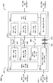
도 2는 도 1의 무선 전력 전송 시스템의 예시적인 핵심 컴포넌트들의 개략도이다.
도 3은 도 1의 무선 전력 전송 시스템의 예시적인 핵심 및 보조 컴포넌트들을 보여주는 다른 기능 블록도이다.
도 4는 본 발명의 예시적 실시형태에 따른, 전기 차량에 배치된 교체가능한 비접촉식 배터리를 보여주는 기능 블록도이다.
도 5a, 도 5b, 도 5c 및 도 5d 는 본 발명의 예시적인 실시형태들에 따른, 배터리에 대한 유도 코일 및 페라이트 재료의 배치를 위한 예시적인 구성들의 도면들이다.
도 6은 본 발명의 예시적인 실시형태에 따른, 전기 차량을 무선 충전하기 위해 이용가능할 수도 있는 예시적인 주파수들을 보여주는 주파수 스펙트럼의 차트이다.
도 7은 본 발명의 예시적인 실시형태에 따른, 전기 차량을 무선 충전하는데 유용할 수도 있는 예시적인 주파수들 및 송신 거리들을 보여주는 차트이다.
도 8a 는, 페라이트 플레이트를 통해 연장되는 한 쌍의 전기 도관들 (예를 들어, 180 도 위상 시프트를 가진, 모두 차동 모드에 있는, 전기 도체 및 귀환 도체) 를 시뮬레이션하는데 사용된 모델 구조를 개략적으로 예시하고, 도 8b 는 이 시뮬레이션의 자속을 예시한다.
도 9는 본원에 기재된 특정 실시형태들에 따른 예시적인 전기 디바이스 (600) 를 개략적으로 예시한다.
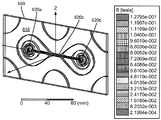
도 10 은, 페라이트 플레이트가 페라이트 플레이트로부터 제거된 재료의 슬라이스를 갖고, 그 슬라이스는 1 mm 의 폭을 갖고 하나의 홀에서부터 다른 것으로 연장되는, 시뮬레이션의 자속을 예시한다.
도 11a 내지 도 11d 는 본원에 기재된 특정 실시형태들에 따른 바람직한 도체 및 페라이트 토폴로지를 갖는 전자 디바이스의 예시적인 부분들을 개략적으로 예시한다.
도 12는 간략화된 구조를 위한 등가 자기 회로를 개략적으로 예시한다.
도 13은 본원에 기재된 특정 실시형태들에 따른 전력을 무선 송신 또는 무선 수신하는 예시적인 방법의 흐름도이다.
도 14는, 무선 전력 전송 시스템의 일부로서 전력을 무선 송신 또는 무선 수신하도록 구성된 전기 디바이스를 제조하는 예시적인 방법의 흐름도이다.
도면들에 예시된 다양한 특징부들은 스케일 (scale) 대로 그려지지 않을 수도 있다. 따라서, 다양한 특징부들의 치수들은 명료성을 위해 임의로 확대 또는 축소될 수도 있다. 또한, 일부의 도면들은 주어진 시스템, 방법 또는 디바이스의 모든 컴포넌트들을 도시하는 것이 아닐 수도 있다. 마지막으로, 같은 도면 부호들은 명세서 및 도면들 전체에 걸쳐 같은 특징부들을 표기하기 위해 사용될 수도 있다.1 is a diagram of an exemplary wireless power transmission system for charging an electric vehicle in accordance with an exemplary implementation of the present invention.
Figure 2 is a schematic diagram of exemplary core components of the wireless power transmission system of Figure 1;
3 is another functional block diagram illustrating exemplary core and supplementary components of the wireless power transmission system of FIG.
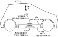
4 is a functional block diagram illustrating a replaceable contactless battery disposed in an electric vehicle, in accordance with an exemplary embodiment of the present invention.
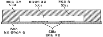
Figures 5A, 5B, 5C, and 5D are illustrations of exemplary configurations for the placement of inductive coils and ferrite material for a battery, in accordance with exemplary embodiments of the present invention.
6 is a chart of frequency spectra showing exemplary frequencies that may be available for wireless charging an electric vehicle, in accordance with an exemplary embodiment of the present invention.
7 is a chart illustrating exemplary frequencies and transmission distances that may be useful for wireless charging an electric vehicle, in accordance with an exemplary embodiment of the present invention.
Figure 8a schematically illustrates the model structure used to simulate a pair of electrical conduits extending through a ferrite plate (e. G., Electrical and return conductors, all in differential mode, with 180 degree phase shift) And Fig. 8B illustrates the magnetic flux of this simulation.
9 schematically illustrates an exemplary
Figure 10 illustrates the flux of simulation in which the ferrite plate has a slice of material removed from the ferrite plate, the slice having a width of 1 mm and extending from one hole to another.
11A-11D schematically illustrate exemplary portions of an electronic device having a preferred conductor and a ferrite topology according to certain embodiments described herein.
Figure 12 schematically illustrates an equivalent magnetic circuit for a simplified structure.
13 is a flow diagram of an exemplary method of wirelessly transmitting or wirelessly receiving power in accordance with certain embodiments described herein.
14 is a flow diagram of an exemplary method of manufacturing an electrical device configured to wirelessly transmit or wirelessly receive power as part of a wireless power transmission system.
The various features illustrated in the Figures may not be drawn on scale. Accordingly, the dimensions of various features may optionally be scaled up or down for clarity. Furthermore, some of the drawings may not be intended to depict all components of a given system, method, or device. Finally, the same reference numerals may be used to denote the same features throughout the specification and drawings.
상세한 설명details
첨부된 도면들과 관련하여 아래에 제시된 상세한 설명은 본 발명의 예시적 실시형태들의 설명으로서 의도된 것이며 본 발명이 실시될 수도 있는 유일한 실시형태들을 나타내도록 의도된 것은 아니다. 본 상세한 설명 전반에 걸쳐 사용된 "예시적" 이라는 용어는 "예, 실례, 또는 예시의 역할을 하는 것" 을 의미하고, 반드시 다른 예시적 실시형태보다 바람직하거나 또는 유리한 것으로 해석되는 것은 아니다. 상세한 설명은 본 발명의 예시적 실시형태의 완전한 이해를 제공하는 목적을 위해 구체적인 상세들을 포함한다. 일부의 사례들에서, 일부 디바이스들은 블록도 형태로 도시되어 있다.The following detailed description in conjunction with the appended drawings is intended as a description of exemplary embodiments of the invention and is not intended to represent the only embodiments in which the invention may be practiced. The word "exemplary" used throughout this specification does not necessarily mean that it is acting as an example, instance, or illustration, and is not necessarily preferred or advantageous over other exemplary embodiments. The detailed description includes specific details for the purpose of providing a thorough understanding of the exemplary embodiments of the invention. In some cases, some devices are shown in block diagram form.
전력을 무선으로 전송한다는 것은, 전기장, 자기장, 전자기장, 또는 다른 것과 연관되는 임의의 형태의 에너지를, 물리적인 전기 도체들의 사용 없이 송신기로부터 수신기로 전송하는 것을 의미할 수도 있다 (예를 들면, 전력은 자유 공간을 통해 전송될 수도 있다). 무선 필드 (예를 들면, 자기장) 로 출력된 전력은, "수신 코일" 에 의해 수신되거나, 포획되거나, 또는 커플링되어 전력 전송을 달성할 수도 있다.Transmitting power wirelessly may mean transmitting any form of energy associated with an electric field, magnetic field, electromagnetic field, or the like from the transmitter to the receiver without the use of physical electrical conductors (e.g., power May be transmitted via free space). Power output to a wireless field (e.g., a magnetic field) may be received, captured, or coupled by a "receive coil" to achieve power transfer.
전기 차량은, 본원에서 원격 시스템을 기술하기 위하여 사용되고, 그의 예는, 그의 운동 능력의 일부로서, 충전가능한 에너지 저장 디바이스 (예를 들어, 하나 이상의 재충전가능한 전기화학 셀들 또는 다른 타입의 배터리) 로부터 도출되는 전력을 포함하는 차량이다. 비제한적인 예들로서, 일부 전기 차량들은, 전기 모터들이외에, 직접 운동을 위해 또는 차량의 배터리를 충전하기 위한 통상적인 내연 기관을 포함하는 하이브리드 전기 차량들일 수도 있다. 다른 전기 차량들은 전력으로부터 모든 운동 능력을 이끌어낼 수도 있다. 전기 차량은 자동차에 한정되지 않고 모터사이클, 카트, 스쿠터 등을 포함할 수도 있다. 비제한적인 예로써, 원격 시스템은 본원에서 전기 차량 (EV) 의 형태로 기술된다. 게다가, 충전가능한 에너지 저장 디바이스를 사용하여 적어도 부분적으로 전력 공급될 수도 다른 원격 시스템들 (예를 들어, 개인용 컴퓨팅 디바이스들 등과 같은 전자 디바이스들) 이 또한 고려된다.An electric vehicle is used herein to describe a remote system, an example of which is derived from a rechargeable energy storage device (e.g., one or more rechargeable electrochemical cells or other types of batteries) ≪ / RTI > By way of non-limiting example, some electric vehicles may be hybrid electric vehicles, including electric motors, as well as conventional internal combustion engines for direct motion or for charging the vehicle's battery. Other electric vehicles may draw all the athletic ability from power. The electric vehicle is not limited to an automobile, but may include a motorcycle, a cart, a scooter, and the like. As a non-limiting example, the remote system is described herein in the form of an electric vehicle (EV). In addition, other remote systems (e.g., electronic devices such as personal computing devices) that may be at least partially powered using a rechargeable energy storage device are also contemplated.
도 1은 본 발명의 예시적인 구현에 따른, 전기 차량 (112) 을 충전하기 위한 예시적인 무선 전력 전송 시스템 (100) 의 도면이다. 무선 전력 전송 시스템 (100) 은, 전기 차량 (112) 이 베이스 무선 충전 시스템 (102a) 근처에 주차되어 있는 동안 전기 차량 (112) 의 충전을 가능하게 한다. 2개의 전기 차량들을 위한 공간들이, 대응하는 베이스 무선 충전 시스템 (102a 및 102b) 위에 주차될 주차 구역에 예시되어 있다. 일부 실시형태들에서, 로컬 분배 센터 (130) 는 전력 백본 (132) 에 접속될 수도 있고 교류 (AC) 또는 직류 (DC) 공급을 전력 링크 (110) 를 통해 베이스 무선 충전 시스템 (102a) 에 제공하도록 구성될 수도 있다. 베이스 무선 충전 시스템 (102a) 은 또한, 전력을 무선 전송 또는 수신하기 위한 베이스 시스템 유도 코일 (104a) 을 포함한다. 전기 차량 (112) 은, 배터리 유닛 (118), 전기 차량 유도 코일 (116), 및 전기 차량 무선 충전 시스템 (114) 을 포함할 수도 있다. 전기 차량 유도 코일 (116) 은 베이스 시스템 유도 코일 (104a) 과 예를 들어, 베이스 시스템 유도 코일 (104a) 에 의해 생성된 전자기장의 영역을 통해 상호작용할 수도 있다.1 is a diagram of an exemplary wireless
일부 예시적인 실시형태들에서, 전기 차량 유도 코일 (116) 은, 전기 차량 유도 코일 (116) 이 베이스 시스템 유도 코일 (104a) 에 의해 생성된 에너지 필드 (energy field) 에 위치될 때 전력을 수신할 수도 있다. 그 필드는, 베이스 시스템 유도 코일 (104a) 에 의해 출력된 에너지가 전기 차량 유도 코일 (116) 에 의해 포획될 수도 있는 영역에 대응한다. 예를 들어, 베이스 시스템 유도 코일 (104a) 에 의해 출력된 에너지는, 전기 차량 (112) 을 충전하거나 또는 전력 공급하기에 충분한 레벨일 수도 있다. 일부 경우들에서, 그 필드는 베이스 시스템 유도 코일 (104a) 의 "근접장" 에 대응할 수도 있다. 근접장은, 베이스 시스템 유도 코일 (104a) 로부터 멀리 전력을 방출하지 않는 베이스 시스템 유도 코일 (104a) 에서 전류 및 전하로부터 생기는 강한 반응성 필드가 있는 영역에 대응할 수도 있다. 일부 경우들에서 근접장은, 아래에서 더 설명될 바처럼 베이스 시스템 유도 코일 (104a) (그리고 전기 차량 유도 코일 (116) 대해서는 그 반대) 의 파장의 약 1/2π 내에 있는 영역에 대응할 수도 있다.In some exemplary embodiments, the electric
로컬 분배부 (local distribution; 130) 는, 통신 백홀 (134) 을 통해 외부 소스 (예를 들어, 전력 그리드) 와, 그리고 통신 링크 (108) 를 통해 베이스 무선 충전 시스템 (102a) 과 통신하도록 구성될 수도 있다. The
일부 실시형태들에서 전기차량 유도 코일 (116) 은 베이스 시스템 유도 코일 (104a) 과 정렬될 수도 있고, 따라서, 베이스 시스템 유도 코일 (104a) 에 대해 올바르게 전기 차량 (112) 을 배치하는 운전자에 의해 간단히 근접장 영역 내에 배치될 수도 있다. 다른 실시형태들에서, 운전자에게는, 전기 차량 (112) 이 무선 전력 전송을 위해 적절히 위치된 때를 결정하기 위하여 시각적 피드백, 청각적 피드백, 또는 이들의 조합이 주어질 수도 있다. 또 다른 실시형태들에서, 전기 차량 (112) 은 자동조종 시스템에 의해 배치될 수도 있고, 이 자동조종 시스템은 정렬 오차가 허용 값에 도달할 때까지 전기 차량 (112) 을 앞뒤로 (예를 들어, 지그재그 이동으로) 이동시킬 수도 있다. 이것은, 전기 차량 (112) 에 서보 조향 핸들, 초음파 센서, 및 차량을 조정하기 위한 지능이 구비된다면, 운전자 개입 없이 또는 최소 운전자 개입만으로 전기 차량 (112) 에 의해 자동적으로 또는 자체적으로 수행될 수도 있다. 또 다른 실시형태들에서, 전기 차량 유도 코일 (116), 베이스 시스템 유도 코일 (104a), 또는 이들의 조합은, 유도 코일들 (116 및 104a) 을 서로에 대해 변위시키고 이동시켜 그들을 보다 정확하게 배향시키고 그들간에 보다 효율적인 커플링을 전개하기 위한 기능을 가질 수도 있다.In some embodiments, the electric
베이스 무선 충전 시스템 (102a) 은 다양한 장소들에 위치될 수도 있다. 비제한적 예들로서, 일부 적합한 장소들은, 전기 차량 (112) 소유자의 집에 있는 주차 구역, 종래 주유소를 본떠서 만들어진 전기 차량 무선 충전을 위해 따로 두어진 주차 구역, 및 쇼핑 센터 및 직장과 같은 다른 장소들에 있는 주차장을 포함한다.The base
전기 차량을 무선으로 충전하는 것은 많은 혜택들을 제공할 수도 있다. 예를 들어, 충전은 운전자 개입 및 조작 없이 자동적으로, 시각적으로 수행됨으로써 사용자에 대한 편의성을 향상시킬 수도 있다. 또한, 노출되는 전기 접점들 및 기계적인 마모가 없으므로, 무선 전력 전송 시스템 (100) 의 신뢰성을 향상시킬 수도 있다. 케이블 및 커넥터 관련 조작이 필요하지 않을 수도 있고, 실외 환경에서 습기 및 물에 노출될 수도 있는 케이블, 플러그 또는 소켓이 없으므로, 안전성을 향상시킬 수도 있다. 또한, 가시적 또는 액세스가능한 소켓, 케이블 및 플러그가 없으므로, 전력 충전 디바이스들의 잠재적인 반달리즘을 감소시킬 수도 있다. 또한, 전기 차량 (112) 은 전력 그리드를 안정화하기 위한 분배된 저장 디바이스들로서 사용될 수도 있으므로, 도킹 투 그리드 (docking-to-grid) 해법은 비클 투 그리드 (Vehicle-to-Grid; V2G) 동작을 위한 차량들의 이용가능성을 증가시키는데 사용될 수도 있다.Charging an electric vehicle wirelessly may provide many benefits. For example, charging may be performed visually, automatically and without driver intervention and manipulation, thereby improving convenience for the user. In addition, there is no exposed electrical contacts and no mechanical wear, thus improving the reliability of the wireless
도 1을 참조하여 설명된 무선 전력 전송 시스템 (100) 은 또한, 심미적 그리고 비방해적인 이점들을 제공할 수도 있다. 예를 들어, 차량 및/또는 보행자에 방해가 될 수도 있는 충전 기둥 및 케이블이 없을 수도 있다.The wireless
비클 투 그리드 능력의 추가 설명으로서, 무선 전력 송신 및 수신 능력들은, 베이스 무선 충전 시스템 (102a) 이 전력을 전기 차량 (112) 에 전송하고 예를 들어, 에너지 부족 시간에는 전기 차량 (112) 이 전력을 베이스 무선 충전 시스템 (102a) 으로 전송하도록 역으로 구성될 수도 있다. 이 능력은, 재생 에너지 생산 (예를 들어, 풍력 또는 태양광) 에 있어서 과수요 또는 부족에 의해 야기되는 에너지 부족의 시간에 전기 차량이 전력을 전체 분배 시스템으로 제공할 수 있게 함으로써 전력 분배 그리드를 안정화시키는데 유용할 수도 있다.As a further illustration of the bill-to-grid capability, the wireless power transmission and reception capabilities are such that the base
도 2는 도 1의 무선 전력 전송 시스템 (100) 의 예시적인 핵심 컴포넌트들의 개략도이다. 도 2에 도시된 바처럼, 무선 전력 전송 시스템 (200) 은, 인덕턱스 L1 를 갖는 베이스 시스템 유도 코일 (204) 을 포함하는 베이스 시스템 송신 회로 (206) 를 포함할 수도 있다. 무선 전력 전송 시스템 (200) 은, 인덕턴스 L2 를 갖는 전기 차량 유도 코일 (216) 을 포함하는 전기 차량 수신 회로 (222) 를 더 포함한다. 여기에 기재된 실시형태들은, 1차 및 2차 양자 모두가 공통 공진 주파수로 튜닝되면 1차 구조 (송신기) 로부터 2차 구조 (수신기) 로 자기 또는 전자기 근접 장을 통해 에너지를 효율적으로 커플링할 수 있는 공진 구조를 형성하는 용량성 부하의 와이어 루프들 (즉, 멀티턴 코일) 을 사용할 수도 있다. 코일들이 전기 차량 유도 코일 (216) 및 베이스 시스템 유도 코일 (204) 에 사용될 수도 있다. 에너지를 커플링하기 위해 공진 구조들을 사용하는 것은 "자기 커플링된 공진", "전자기 커플링된 공진", 및/또는 "공진 유도" 로 지칭될 수도 있다. 무선 전력 전송 시스템 (200) 의 동작은 베이스 무선 전력 충전 시스템 (202) 으로부터 전기 차량 (112) 으로의 전력 전송에 기초하여 설명될 것이지만, 이에 한정되지 않는다. 예를 들어, 위에서 논의된 바처럼, 전기 차량 (112) 은 전력을 베이스 무선 충전 시스템 (102a) 으로 전송할 수도 있다.2 is a schematic diagram of exemplary core components of the wireless
도 2를 참조하여, 전력 공급부 (208) (예를 들어, AC 또는 DC) 는, 에너지를 전기 차량 (112) 으로 전송하기 위해 전력 PSDC 을 베이스 무선 전력 충전 시스템 (202) 에 공급한다. 베이스 무선 전력 충전 시스템 (202) 은 베이스 충전 시스템 전력 컨버터 (236) 를 포함한다. 베이스 충전 시스템 전력 컨버터 (236) 는, 전력을 표준 주된 AC 로부터 적합한 전압 레벨의 DC 전력으로 컨버팅하도록 구성된 AC/DC 컨버터, DC 전력을 무선 고 전력 전송에 적합한 동작 주파수의 전력으로 컨버팅하도록 구성된 DC/저주파 (LF) 컨버터 등과 같은 회로를 포함할 수도 있다. 베이스 충전 시스템 전력 컨버터 (236) 는, 원하는 주파수의 전자기장으로 방출하기 위해 베이스 시스템 유도 코일 (204) 과 직렬로 커패시터 C1 를 포함하는 베이스 시스템 송신 회로 (206) 에 전력 P1 를 공급한다. 커패시터 C1 는, 원하는 주파수에서 공진하는 베이스 시스템 유도 코일 (204) 과 공진 회로를 형성하기 위해 제공될 수도 있다. 베이스 시스템 유도 코일 (204) 은, 전력 P1 을 수신하고, 전기 차량 (112) 을 충전 또는 전력 공급하는데 충분한 레벨의 전력을 무선 송신한다. 예를 들어, 베이스 시스템 유도 코일 (204) 에 의해 무선으로 제공되는 전력 레벨은, 수 킬로와트 (kW) (예를 들어, 1 kW 내지 110 kW 이상 또는 이하) 정도일 수도 있다.2, a power supply 208 (e.g., AC or DC) supplies power P SDC to base radio
베이스 시스템 유도 코일 (204) 을 구비하는 베이스 시스템 송신 회로 (206) 및 전기 차량 유도 코일 (216) 을 구비하는 전기 차량 수신 회로 (222) 는 실질적으로 동일한 주파수로 튜닝될 수도 있고 베이스 시스템 유도 코일 (204) 및 전기 차량 유도 코일 (116) 중 하나에 의해 송신된 전자기장의 근접장 내에 배치될 수도 있다. 이 경우에, 베이스 시스템 유도 코일 (204) 및 전기 차량 유도 코일 (116) 은, 커패시터 C2 및 전기 차량 유도 코일 (116) 을 포함하는 전기 차량 수신 회로 (222) 에 전력이 전송될 수 있도록 서로 커플링될 수도 있다. 커패시터 C2 는, 원하는 주파수에서 공진하는 전기 차량 유도 코일 (216) 과 공진 회로를 형성하기 위해 제공될 수도 있다. 엘리먼트 k(d) 는 코일 이격에서 생기는 상호 커플링 계수를 나타낸다. 등가 저항 Req,1 및 Req,2 는, 유도 코일 (204 및 216) 및 안티 리액턴스 (anti-reactance) 커패시터 C1 및 C2 에 고유할 수도 있는 손실을 나타낸다. 전기 차량 유도 코일 (316) 및 커패시터 C2 를 포함하는 전기 차량 수신 회로 (222) 는 전력 P2 를 수신하고 전력 P2 를 전기 차량 충전 시스템 (214) 의 전기 차량 전력 컨버터 (238) 에 제공한다. The base
전기 차량 전력 컨버터 (238) 는, 다른 것들 중에서도, 전기 차량 배터리 유닛 (218) 의 전압 레벨에 매칭되는 전압 레벨의 DC 전력으로 동작 주파수의 전력을 다시 컨버팅하도록 구성된 LF/DC 컨버터를 포함할 수도 있다. 전기 차량 전력 컨버터 (238) 는 전기 차량 배터리 유닛 (218) 을 충전하기 위해 컨버팅된 전력 PLDC 를 제공할 수도 있다. 전력 공급부 (208), 베이스 충전 시스템 전력 컨버터 (236), 및 베이스 시스템 유도 코일 (204) 은 고정식일 수도 있고 위에 논의된 다양한 장소들에 위치될 수도 있다. 배터리 유닛 (218), 전기 차량 전력 컨버터 (238), 및 전기 차량 유도 코일 (216) 은, 전기 차량 (112) 의 부분 또는 배터리 팩 (미도시) 의 부분인 전기 차량 충전 시스템 (214) 에 포함될 수도 있다. 전기 차량 충전 시스템 (214) 은 또한, 전력을 다시 그리드에 공급하기 위해 전기 차량 유도 코일 (216) 을 통해 베이스 무선 전력 충전 시스템 (202) 으로 전력을 무선으로 제공하도록 구성될 수도 있다. 전기 차량 유도 코일 (216) 및 기지국 유도 코일 (204) 의 각각은 동작 모드에 기초하여 송신 또는 수신 유도 코일들로서 작용할 수도 있다.The electric
도시되지는 않았지만, 무선 전력 전송 시스템 (200) 은, 전기 차량 배터리 유닛 (218) 또는 전력 공급부 (208) 를 무선 전력 전송 시스템 (200) 으로부터 안전하게 분리하기 위해 부하 분리 유닛 (LDU) 을 포함할 수도 있다. 예를 들어, 비상 또는 시스템 고장의 경우에, LDU 는 무선 전력 전송 시스템 (200) 으로부터 부하를 분리시키기 위해 트리거될 수도 있다. LDU 는, 배터리로의 충전을 관리하는 배터리 관리 시스템에 추가로 제공될 수도 있거나, 또는 배터리 관리 시스템의 일부일 수도 있다. Although not shown, the wireless
또한, 전기 차량 충전 시스템 (214) 은, 전기 차량 유도 코일 (216) 을 전기 차량 전력 컨버터 (238) 로 선택적으로 접속 및 분리하기 위한 스위칭 회로 (미도시) 를 포함할 수도 있다. 전기 차량 유도 코일 (216) 을 분리시키는 것은, 충전을 중단시키고 또한, (송신기로서 작용하는) 베이스 무선 충전 시스템 (102a) 에 의해 "겪게되는" "부하" 를 조정할 수도 있는데, 이는 베이스 무선 충전 시스템 (102a) 으로부터 (수신기로서 작용하는) 전기 차량 충전 시스템 (114) 을 "클로킹" (cloaking) 하는데 사용될 수도 있다. 송신기가 부하 감지 회로를 포함하면, 부하 변화가 검출될 수도 있다. 따라서, 베이스 무선 충전 시스템 (202) 과 같은 송신기는, 전기 차량 충전 시스템 (114) 과 같은 수신기가 베이스 시스템 유도 코일 (204) 의 근접장에 존재할 때를 결정하기 위한 메카니즘을 가질 수도 있다.The electric
위에 언급된 바처럼, 동작시, 차량 또는 배터리쪽으로의 전력 전송을 가정하면, 입력 전력이 전력 공급부 (208) 로부터 제공되어, 베이스 시스템 유도 코일 (204) 은 에너지 전송을 제공하기 위한 필드를 생성한다. 전기 차량 유도 코일 (216) 은 방사된 필드에 커플링되고 전기 차량 (112) 에 의한 저장 또는 소비를 위해 출력 전력을 생성한다. 위에 설명된 바처럼, 일부 실시형태들에서, 베이스 시스템 유도 코일 (204) 및 전기 차량 유도 코일 (116) 은, 전기 차량 유도 코일 (116) 의 공진 주파수 및 베이스 시스템 유도 코일 (204) 의 공진 주파수가 매우 비슷하거나 또는 실질적으로 동일하도록 상호 공진 관계에 따라 구성된다. 베이스 무선 전력 충전 시스템 (202) 및 전기 차량 충전 시스템 (214) 사이의 송신 손실은, 전기 차량 유도 코일 (216) 이 베이스 시스템 유도 코일 (204) 의 근접장에 위치될 때 최소이다. Assuming power transmission to the vehicle or battery in operation, as noted above, input power is provided from the
언급된 바와 같이, 전자기파에서 에너지의 대부분을 원격장 (far-field) 에 전파하기보다는 송신 유도 코일의 근접장에서 에너지의 대부분을 수신 유도 코일에 커플링시킴으로써 효율적인 에너지 전송이 발생한다. 근접장에 있을 때, 송신 유도 코일과 수신 유도 코일 사이에 커플링 모드가 확립될 수도 있다. 이러한 근접장 커플링이 발생할 수도 있는 유도 코일 주위 지역은 근접장 커플링 모드 영역으로 지칭된다.As mentioned, efficient energy transfer occurs by coupling most of the energy in the near field of the transmission induction coil to the receiving induction coil, rather than propagating most of the energy in the electromagnetic waves to the far-field. When in the near field, a coupling mode may be established between the transmission induction coil and the reception induction coil. The area around the induction coil, where such near field coupling may occur, is referred to as the near field coupling mode region.
도시되지 않았지만, 베이스 충전 시스템 전력 컨버터 (236) 및 전기 차량 전력 컨버터 (238) 는 양자 모두 오실레이터, 전력 증폭기와 같은 구동 회로, 필터, 및 무선 전력 유도 코일과의 효율적인 커플링을 위한 매칭 회로를 포함할 수도 있다. 오실레이터는 조정 신호에 응답하여 조정될 수도 있는 원하는 주파수를 생성하도록 구성될 수도 있다. 오실레이터 신호는 제어 신호에 응답한 증폭량으로 전력 증폭기에 의해 증폭될 수도 있다. 고조파 또는 다른 원치않는 주파수를 필터링해내고 전력 컨버젼 모듈의 임피던스를 무선 전력 유도 코일에 매칭시키기 위해 필터 및 매칭 회로가 포함될 수도 있다. 전력 컨버터들 (236 및 238) 은 또한, 배터리를 충전시키는데 적합한 전력 출력을 생성하기 위하여 정류기 및 스위칭 회로를 포함할 수도 있다. Although not shown, base charging
개시된 실시형태들 전체에 걸쳐 설명된 전기 차량 유도 코일 (216) 및 베이스 시스템 유도 코일 (204) 은 "루프" 안테나, 및 보다 구체적으로는, 멀티턴 루프 안테나들로 지칭되거나 또는 구성될 수도 있다. 유도 코일들 (204 및 216) 은 또한, 본원에서 "자기" 안테나들로 지칭되거나 또는 구성될 수도 있다. 용어 "코일" 은 일반적으로, 다른 "코일" 로의 커플링을 위한 에너지를 무선 출력 또는 수신할 수도 있는 컴포넌트를 지칭한다. 코일은 또한, 전력을 무선 출력 또는 수신하도록 구성된 일종의 "안테나"로서 지칭될 수도 있다. 본원에 사용된 바처럼, 코일들 (204 및 216) 은, 전력을 무선 출력, 무선 수신, 및/또는 무선 중계하도록 구성되는 일종의 "전력 전송 컴포넌트들" 의 예들이다. 루프 (예를 들어, 멀티턴 루프) 안테나들은 페라이트 코어와 같은 물리적 코어 또는 공심 (air core) 을 포함하도록 구성될 수도 있다. 공심 루프 안테나는 코어 영역 내에 다른 컴포넌트들의 배치를 허용할 수도 있다. 강자성 또는 강자성 재료를 포함하는 물리적 코어 안테나들은 더 강한 전자기 장의 전개 및 향상된 커플링을 허용할 수도 있다. The electric
위에 언급된 바처럼, 송신기와 수신기 사이의 에너지의 효율적인 전송은 송신기와 수신기 사이의 매칭된 또는 거의 매칭된 공진 동안에 발생한다. 그러나, 송신기와 수신기 사이의 공진이 매칭되지 않는 경우에도, 에너지가 저효율로 전송될 수도 있다. 송신 유도 코일로부터 자유 공간으로 에너지를 전파시키기보다는 송신 유도 코일의 근접장으로부터, 이 근접장이 확립된 영역 내에 (예를 들어, 공진 주파수의 미리결정된 주파수 범위 내, 또는 근접장 영역의 미리결정된 거리 내) 상주하는 수신 유도 코일로 에너지를 커플링함으로써 에너지의 전송이 일어난다. As mentioned above, efficient transmission of energy between the transmitter and receiver occurs during matched or nearly matched resonance between the transmitter and the receiver. However, even if the resonance between the transmitter and the receiver is not matched, energy may be transmitted with low efficiency. Rather than propagating energy from the transmission induction coil to the free space, it is possible to determine from the near field of the transmission induction coil that this near field is within the established region (e.g. within a predetermined frequency range of the resonant frequency, or within a predetermined distance of the near- The transmission of energy occurs by coupling energy to the receiving induction coil.
공진 주파수는 위에 설명된 바처럼 유도 코일 (예를 들어, 베이스 시스템 유도 코일 (204)) 을 포함하는 송신 회로의 인덕턴스 및 커패시턴스에 기초할 수도 있다. 도 2에 나타낸 바처럼, 인덕턴스는 일반적으로 유도 코일의 인덕턴스일 수도 있지만, 원하는 공진 주파수에서 공진 구조를 만들기 위해 커패시턴스가 유도 코일에 추가될 수도 있다. 비제한적 예로서, 도 2에 나타낸 바처럼, 전자기장을 생성하는 공진 회로 (예를 들어, 베이스 시스템 송신 회로 (206)) 를 만들기 위하여 커패시터가 유도 코일과 직렬로 추가될 수도 있다. 따라서, 더 큰 직경의 유도 코일들의 경우, 공진을 유도하는데 필요한 커패시턴스의 값은, 그 코일의 직경 또는 인덕턴스가 증가함에 따라 감소할 수도 있다. 인덕턴스는 또한, 유도 코일의 감은 수에 의존할 수도 있다. 또한, 유도 코일의 직경이 증가함에 따라, 근접장의 효율적인 에너지 전송 영역이 증가할 수도 있다. 다른 공진 회로들도 가능하다. 다른 비제한적 예로서, 커패시터는 유도 코일 (예를 들어, 병렬 공진 회로) 의 2 개의 단자들 사이에서 병렬로 배치될 수도 있다. 또한, 유도 코일은 유도 코일의 공진을 향상시키기 위하여 고품질 (Q) 계수를 갖도록 설계될 수도 있다. 예를 들어, Q 계수는 300 이상일 수도 있다.The resonant frequency may be based on the inductance and capacitance of the transmitting circuit including the induction coil (e.g., the base system induction coil 204) as described above. As shown in FIG. 2, the inductance may generally be the inductance of the induction coil, but a capacitance may be added to the induction coil to create a resonance structure at the desired resonance frequency. As a non-limiting example, a capacitor may be added in series with the induction coil to create a resonant circuit (e. G., A base system transmit circuit 206) that produces an electromagnetic field, as shown in FIG. Thus, for larger diameter induction coils, the value of the capacitance required to induce resonance may decrease as the diameter or inductance of the coil increases. The inductance may also depend on the number of turns of the induction coil. Also, as the diameter of the induction coil increases, the effective energy transfer region of the near field may increase. Other resonant circuits are possible. As another non-limiting example, the capacitors may be arranged in parallel between two terminals of an induction coil (e.g., a parallel resonant circuit). Further, the induction coil may be designed to have a high quality (Q) coefficient to improve the resonance of the induction coil. For example, the Q factor may be 300 or more.
위에 설명된 바처럼, 일부 실시형태들에 따르면, 서로의 근접장에 있는 2개 유도 코일들 사이의 전력 커플링이 개시된다. 위에 설명된 바처럼, 근접장은, 전자기장이 존재할 수도 있지만, 유도 코일로부터 멀리 전파 또는 방사되지 않을 수도 있는 유도 코일 주위 영역에 대응할 수도 있다. 근접장 커플링 모드 영역들은, 유도 코일의 물리적 부피 (volume) 에 근접한, 통상적으로 파장의 작은 부분 이내인 부피에 대응할 수도 있다. 일부 실시형태들에 따르면, 전자기 유도 코일들, 이를테면 단일 및 멀티 턴 루프 안테나들이 송신 및 수신 양자 모두에 사용되는데, 왜냐하면 실제 실시형태들에서 자기 근접장 진폭이, 전기 타입 안테나 (예를 들어, 소형 쌍극자) 의 전기 근접장과 비교하여 자기 타입 코일에 대해 더 높은 경향이 있기 때문이다. 이것은 그 쌍간의 잠재적으로 더 높은 커플링을 허용한다. 또한, "전기" 안테나 (예를 들어, 쌍극자 및 단극자) 또는 자기 및 전기 안테나의 조합이 사용될 수도 있다.As described above, according to some embodiments, power coupling between two inductive coils in close proximity to each other is disclosed. As described above, the near field may correspond to an area around the induction coil, which may or may not be propagated away from the induction coil, although electromagnetic fields may be present. The near field coupling mode regions may correspond to volumes that are within a small fraction of the wavelength, typically close to the physical volume of the induction coil. According to some embodiments, electromagnetic induction coils, such as single and multi-turn loop antennas, are used for both transmission and reception, because in practical embodiments the near field amplitudes are dependent on the electrical type antenna (e.g., Because there is a higher tendency for magnetic type coils as compared to the electrical near field of magnetic type coils. This allows a potentially higher coupling between the pair. Also, a "electrical" antenna (e.g., dipole and unipolar) or a combination of magnetic and electrical antennas may be used.
도 3은 도 1의 무선 전력 전송 시스템 (300) 의 예시적인 핵심 및 보조 컴포넌트들을 보여주는 다른 기능 블록도이다. 무선 전력 전송 시스템 (300) 은 통신 링크 (376), 안내 링크 (366), 및 베이스 시스템 유도 코일 (304) 및 전기 차량 유도 코일 (316) 을 위한 정렬 시스템들 (352, 354) 을 예시한다. 도 2을 참조하여 위에서 설명된 바처럼, 그리고 전기 차량 (112) 을 향한 에너지 흐름을 가정하면, 도 3에서 베이스 충전 시스템 전력 인터페이스 (354) 는, AC 또는 DC 전력 공급부 (126) 와 같은 전원으로부터 충전 시스템 전력 컨버터 (336) 로 전력을 제공하도록 구성될 수도 있다. 베이스 충전 시스템 전력 컨버터 (336) 는, 베이스 충전 시스템 전력 인터페이스 (354) 로부터 AC 또는 DC 전력을 수신하여 베이스 시스템 유도 코일 (304) 을 그의 공진 주파수 또는 그 근처에서 여기할 수도 있다. 전기 차량 유도 코일 (316) 은, 근접 장 커플링 모드 영역에 있을 때, 근접장 커플링 모드 영역으로부터 에너지를 수신하여 공진 주파수 또는 그 근처에서 공진할 수도 있다. 전기 차량 전력 컨버터 (338) 는 전기 차량 유도 코일 (316) 로부터의 발진 신호를 전기 차량 전력 인터페이스를 통한 배터리 충전에 적합한 전력 신호로 변환한다.3 is another functional block diagram illustrating exemplary core and supplementary components of the wireless
베이스 무선 충전 시스템 (302) 은 베이스 충전 시스템 제어기 (342) 를 포함하고, 전기 차량 충전 시스템 (314) 은 전기 차량 제어기 (344) 를 포함한다. 베이스 충전 시스템 제어기 (342) 는, 예를 들어, 컴퓨터, 및 전력 분배 센터, 또는 스마트 전력 그리드 등의 다른 시스템 (미도시) 에 대한 베이스 충전 시스템 통신 인터페이스 (162) 를 포함할 수도 있다. 전기 차량 제어기 (344) 는, 예를 들어, 차량 탑재 컴퓨터, 다른 배터리 충전 제어기, 차량 내 다른 전자 시스템, 및 원격 전자 시스템 등의 다른 시스템 (미도시) 에 대한 전기 차량 통신 인터페이스를 포함할 수도 있다.The base
베이스 충전 시스템 제어기 (342) 및 전기 차량 제어기 (344) 는 분리된 통신 채널들과 특정 응용을 위한 서브시스템 또는 모듈을 포함할 수도 있다. 이들 통신 채널들은 분리된 물리 채널들 또는 분리된 논리 채널들일 수도 있다. 비제한적 예들로서, 베이스 충전 정렬 시스템 (352) 은 통신 링크 (376) 를 통해 전기 차량 정렬 시스템 (354) 과 통신하여, 자체적으로 또는 오퍼레이터 지원으로, 베이스 시스템 유도 코일 (304) 및 전기 차량 유도 코일 (316) 을 보다 엄밀하게 정렬하기 위한 피드백 메카니즘을 제공할 수도 있다. 유사하게, 베이스 충전 안내 시스템 (362) 은 안내 링크를 통해 전기 차량 안내 시스템 (364) 과 통신하여, 베이스 시스템 유도 코일 (304) 및 전기 차량 유도 코일 (316) 을 정렬함에 있어서 오퍼레이터를 안내하기 위한 피드백 메카니즘을 제공할 수도 있다. 또한, 베이스 무선 전력 충전 시스템 (302) 과 전기 차량 충전 시스템 (314) 사이의 다른 정보를 통신하기 위한 베이스 충전 통신 시스템 (372) 및 전기 차량 통신 시스템 (374) 에 의해 지원되는 분리된 범용 통신 링크들 (예를 들어, 채널들) 이 있을 수도 잇다. 이 정보는, 전기 차량 특성, 배터리 특성, 충전 상태, 및 베이스 무선 전력 충전 시스템 (302) 및 전기 차량 충전 시스템 (314) 양자 모두의 전력 능력들 그리고 전기 차량 (112) 을 위한 유지 및 진단 데이터에 관한 정보를 포함할 수도 있다. 이들 통신 채널들은, 예를 들어, 블루투스, 지그비, 셀룰러 등과 같은 분리된 물리적 통신 채널들일 수도 있다.The base
전기 차량 제어기 (344) 는 또한, 전기 차량 주 배터리의 충전 및 방전을 관리하는 배터리 관리 시스템 (BMS) (미도시), 마이크로파 또는 초음파 레이더 원리에 기초한 주차 지원 시스템, 반자동 주차 동작을 수행하도록 구성되는 브레이크 시스템, 및 더 높은 주차 정확성을 제공함으로써, 베이스 무선 충전 시스템 (102a) 및 전기 차량 충전 시스템 (114) 중의 어느 것에서 기계적 수평 유도 코일 정렬의 필요성을 감소시킬 수도 있는 대체로 자동화된 주차 "파크 바이 와이어" (park by wire) 를 지원하도록 구성된 조향 핸들 서보 시스템을 포함할 수도 있다. 또한, 전기 차량 제어기 (344) 는 전기 차량 (112) 의 전자장치들과 통신하도록 구성될 수도 있다. 예를 들어, 전기 차량 제어기 (344) 는, 시각적 출력 디바이스 (예를 들어, 대시보드 디스플레이), 음향/오디오 출력 디바이스들 (예를 들어, 버저, 스피커), 기계적 입력 디바이스들 (예를 들어, 키보드, 터치 스크린 및 포인팅 디바이스들, 이를테면 조이스틱, 트랙볼 등), 및 오디오 입력 디바이스들 (예를 들어, 전자 음성 인식을 갖는 마이크로폰) 과 통신하도록 구성될 수도 있다.The
더욱이, 무선 전력 전송 시스템 (300) 은 검출 및 센서 시스템들을 포함할 수도 있다. 예를 들어, 무선 전력 전송 시스템 (300) 은 운전자 또는 차량을 충전 지점으로 적절히 안내하기 위해 시스템에 사용하기 위한 센서들, 필요한 분리/커플링으로 유도 코일을 상호 정렬하기 위한 센서들, 커플링을 달성하기 위해 전기 차량 유도 코일 (316) 이 특정 높이 및/또는 위치로 이동하는 것을 막을 수도 있는 물체들을 검출하기 위한 센서들, 및 시스템의 신뢰적이고, 손상이 없고, 안전한 동작을 수행하기 위해 시스템에 사용하기 위한 안전 센서들을 포함할 수도 있다. 예를 들어, 안전 센서는, 안전 반경을 넘어 무선 전력 유도 코일들 (104a, 116) 에 접근하는 동물 또는 아이들의 존재의 검출, 가열 (유도 가열) 될 수도 있는 베이스 시스템 유도 코일 (304) 근접 금속 물체들의 검출, 베이스 시스템 유도 코일 (304) 상의 백열 물체들과 같은 위험한 이벤트들의 검출, 및 베이스 무선 전력 충전 시스템 (302) 및 전기 차량 충전 시스템 (314) 컴포넌트들의 온도 모니터링을 위한 센서를 포함할 수도 있다.Moreover, the wireless
무선 전력 전송 시스템 (300) 은 또한, 유선 접속을 통한 플러그인 충전을 지원할 수도 있다. 유선 충전 포트는 전기 차량 (112) 으로 전력을 전송하거나 전기 차량 (112) 으로부터 전력을 전송하기 전에 2개의 상이한 충전기들의 출력들을 통합할 수도 있다. 스위칭 회로들은, 무선 충전 및 유선 충전 포트를 통한 충전 양자 모두를 지원하기 위해 필요에 따라 기능성을 제공할 수도 있다.The wireless
베이스 무선 충전 시스템 (302) 과 전기 차량 충전 시스템 (314) 사이에 통신하기 위하여, 무선 전력 전송 시스템 (300) 은 대역내 시그널링 및 RF 데이터 모뎀 (예를 들어, 비면허 대역에서의 무선을 통한 이더넷) 양자 모두를 사용할 수도 있다. 대역외 통신은, 차량 사용자/소유자에게 부가 서비스 (value-add service) 들의 할당을 위한 충분한 대역폭을 제공할 수도 있다. 무선 전력 캐리어의 낮은 깊이 진폭 또는 위상 변조는 최소 간섭을 갖는 대역내 시그널링 시스템의 역할을 할 수도 있다.In order to communicate between the base
또한, 일부 통신은, 특정 통신 안테나들을 이용하지 않고서 무선 전력 링크를 통해 수행될 수도 있다. 예를 들어, 무선 전력 유도 코일들 (304 및 316) 은 또한, 무선 통신 송신기들로서 작용하도록 구성될 수도 있다. 따라서, 베이스 무선 전력 충전 시스템 (302) 의 일부 실시형태들은, 무선 전력 경로 상의 키잉 타입 프로토콜 (keying type protocol) 을 가능하게 하기 위한 제어기 (미도시) 를 포함할 수도 있다. 미리정의된 프로토콜로 미리정의된 인터벌에서 송신 전력 레벨을 키잉 (진폭 시프트 키잉) 하는 것에 의해, 수신기는 송신기로부터 직렬 통신을 검출할 수도 있다. 베이스 충전 시스템 전력 컨버터 (336) 는, 베이스 시스템 유도 코일 (304) 에 의해 생성된 근접장의 부근에서 액티브 전기 차량 수신기의 존재 또는 부재를 검출하기 위한 부하 감지 회로 (미도시) 를 포함할 수도 있다. 예로서, 부하 감지 회로는 전력 증폭기로 흐르는 전류를 모니터링하는데, 이것은 베이스 시스템 유도 코일 (104a) 에 의해 생성된 근접장의 부근에서 액티브 수신기들의 존재 또는 부재에 의해 영향을 받는다. 전력 증폭기 상의 부하에 대한 변화의 검출은, 에너지를 송신하기 위해 발진기를 인에이블시킬지 여부, 액티브 수신기와 통신할지 여부, 또는 이들의 조합을 결정함에 있어서 이용하기 위해, 베이스 충전 시스템 제어기 (342) 에 의해 모니터링될 수도 있다.In addition, some communications may be performed over a wireless power link without using specific communication antennas. For example, the wireless power induction coils 304 and 316 may also be configured to act as wireless communication transmitters. Accordingly, some embodiments of the base wireless
무선 고전력 전송을 가능하게 하기 위하여, 일부 실시형태들은 10 - 60 kHz 이상의 범위의 주파수로 전력을 전송하도록 구성될 수도 있다 (예를 들어, 도 6 참조). 이 저주파 커플링은, 솔리드 스테이트 디바이스를 이용하여 달성될 수도 있는 매우 효율적인 전력 컨버젼을 허용할 수도 있다. 또한, 다른 대역들과 비교하여 무선 시스템들과 연관된 공존 문제가 더 적을 수도 있다.To enable wireless high power transmission, some embodiments may be configured to transmit power at a frequency in the range of 10-60 kHz or higher (e.g., see FIG. 6). This low frequency coupling may allow very efficient power conversion, which may be achieved using a solid state device. In addition, there may be less coexistence problems associated with wireless systems as compared to other bands.
설명된 무선 전력 전송 시스템 (100) 은 재충전가능 또는 교체가능한 배터리들을 포함하는 다양한 전기 차량들 (102) 과 함께 사용될 수도 있다. 도 4는 본 발명의 예시적 실시형태에 따른, 전기 차량 (412) 에 배치된 교체가능한 비접촉식 배터리를 보여주는 기능 블록도이다. 이 실시형태에서, 낮은 배터리 위치는, 무선 전력 인터페이스 (예를 들어, 충전기-대-배터리 무코드 인터페이스 (426)) 를 통합하고 지면에 임베딩된 충전기 (미도시) 로부터 전력을 수신할 수도 있는 전기 차량 배터리 유닛에 유용할 수도 있다. 도 4에서, 전기 차량 배터리 유닛은 재충전가능한 배터리 유닛일 수도 있고, 배터리 격납부 (424) 에 수용될 수도 있다. 전기 차량 배터리 유닛은 또한, 무선 전력 인터페이스 (426) 를 제공하고, 이는, 지면 기반 무선 충전 유닛과 전기 차량 배터리 유닛 사이의 효율적이고 안전한 무선 에너지 전송을 위해 필요에 따라 공진 유도 코일, 전력 변환 회로, 및 다른 제어 및 통신 기능들을 포함하는 전체 전기 차량 무선 전력 서브시스템을 통합할 수도 있다.The described wireless
전기 차량 유도 코일은 전기 차량 배터리 유닛 또는 차체의 바닥측과 동일 높이로 통합되어, 돌출 부분들이 없고 지정된 지면-대-차체 간격 (clearance) 이 유지될 수 있도록 하는 것이 유용할 수도 있다. 이 구성은 전기 차량 무선 전력 서브시스템 전용인 전기 차량 배터리 유닛내 약간의 공간을 필요로 할 수도 있다. 전기 차량 배터리 유닛 (422) 은 또한, 배터리-대-EV 무코드 인터페이스 (422), 및 도 1에 나타낸 베이스 무선 충전 시스템 (102a) 과 전기 차량 (412) 사이에 비접촉식 전력 및 통신을 제공하는 충전기-대-배터리 무코드 인터페이스 (426) 를 포함할 수도 있다.The electric vehicle induction coil may be integrated at the same height as the electric vehicle battery unit or the bottom side of the vehicle body, so that it may be useful to have no protrusions and to maintain a specified ground-to-vehicle clearance. This configuration may require some space in the electric vehicle battery unit dedicated to the electric vehicle radio power subsystem. The electric
일부 실시형태들에서, 그리고 도 1을 참조하여, 베이스 시스템 유도 코일 (104a) 및 전기 차량 유도 코일 (116) 은 고정된 위치에 있을 수도 있고 유도 코일들은 베이스 무선 충전 시스템 (102a) 에 대한 전기 차량 유도 코일 (116) 의 전반적인 배치에 의해 근접장 커플링 영역 내로 오게 된다. 하지만, 에너지 전송을 빠르게, 효율적으로, 그리고 안전하게 수행하기 위하여, 베이스 시스템 유도 코일 (104a) 과 전기 차량 유도 코일 (116) 사이의 거리는 커플링을 향상시키기 위하여 감소될 필요가 있을 수도 있다. 따라서, 일부 실시형태들에서, 베이스 시스템 유도 코일 (104a) 및/또는 전기 차량 유도 코일 (116) 이 그것들을 더 좋게 정렬시키기 위하여 전개가능하거나 및/또는 이동가능할 수도 있다.In some embodiments and with reference to Figure 1, the base
도 5a, 도 5b, 도 5c 및 도 5d 는 본 발명의 예시적인 실시형태들에 따른, 배터리에 대한 유도 코일 및 페라이트 재료의 배치를 위한 예시적인 구성들의 도면들이다. 도 5a 는 전체 페라이트 임베딩된 유도 코일 (536a) 을 도시한다. 무선 전력 유도 코일은 페라이트 재료 (538a) 및 페라이트 재료 (538a) 주위에 권취된 코일 (536a) 을 포함할 수도 있다. 코일 (536a) 그 자체는 꼬인 리츠선 (stranded Litz wire) 으로 만들어질 수도 있다. 전도성 실드 (532a) 는 과도한 EMF 송신으로부터 차량의 승객들을 보호하기 위하여 제공될 수도 있다. 전도성 실딩은 특히 플라스틱 또는 복합재로 만들어진 차량들에서 유용할 수도 있다. Figures 5A, 5B, 5C, and 5D are illustrations of exemplary configurations for the placement of inductive coils and ferrite material for a battery, in accordance with exemplary embodiments of the present invention. 5A shows an entire ferrite embedded
도 5b 는, 커플링을 향상시키고 전도성 실드 (532b) 에서 와전류 (열 방산) 을 감소시키기 위한 최적 치수의 페라이트 플레이트 (optimally dimensioned ferrite plate) (즉, 페라이트 백킹) 을 도시한다. 코일 (536b) 은 비전도성 비자기성 (예를 들어, 플라스틱) 재료에 전체적으로 임베딩될 수도 있다. 예를 들어, 도 5a 내지 도 5d 에 예시된 바처럼, 코일 (536b) 은 보호 하우징 (534b) 에 임베딩될 수도 있다. 자기 커플링과 페라이트 이력 손실 사이의 절충의 결과로서 코일 (536b) 과 페라이트 재료 (538b) 사이에 이격이 있을 수도 있다.Figure 5b illustrates an optimally dimensioned ferrite plate (i.e., ferrite backing) for improving coupling and reducing eddy currents (heat dissipation) in the
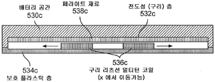
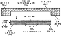
도 5c 는 코일 (536c) (예를 들어, 구리 리츠선 멀티턴 코일) 이 가로 (“X”) 방향으로 이동가능할 수도 있는 다른 실시형태를 예시한다. 도 5d 는 유도 코일 모듈이 하방 방향으로 전개되는 다른 실시형태를 예시한다. 일부 실시형태들에서, 배터리 유닛은 무선 전력 인터페이스의 일부로서 전개가능 및 비전개가능 전기 차량 유도 코일 모듈 (540d) 중 하나를 포함한다. 자기장이 배터리 공간 (530d) 으로 그리고 차량의 내부로 침투하는 것을 방지하기 위하여, 배터리 공간 (530d) 과 차량 사이에 전도성 실드 (532d) (예를 들어, 구리 시트) 가 있을 수도 있다. 또한, 비전도성 (예를 들어, 플라스틱) 보호 층 (533d) 이 전도성 실드 (532d), 코일 (536d), 및 페라이트 재료 (538d) 를 환경 영향들 (예를 들어, 기계적 손상, 산화 등) 으로부터 보호하는데 사용될 수도 있다. 게다가, 코일 (536d) 은 가로 X 및/또는 Y 방향으로 이동가능할 수도 있다. 도 5d 는 전기 차량 유도 코일 모듈 (540d) 이 배터리 유닛 몸체에 대해 하방 Z 방향으로 전개되는 실시형태를 예시한다.5C illustrates another embodiment in which
이 전개가능한 전기 차량 유도 코일 모듈 (542b) 의 설계는, 전기 차량 유도 코일 모듈 (542d) 에서 전도성 실딩이 없는 것을 제외하고는 도 5b 와 유사하다. 전도성 실드 (532d) 는 배터리 유닛 바디와 함께 머문다. 전기 차량 유도 코일 모듈 (542d) 이 전개된 상태에 있지 않을 때 보호 층 (533d) (예를 들어, 플라스틱 층) 이 전도성 실드 (432d) 와 전기 차량 유도 코일 모듈 (542d) 사이에 제공된다. 배터리 유닛 몸체로부터 전기 차량 유도 코일 모듈 (542) 의 물리적 이격은 유도 코일의 성능에 긍정적인 효과를 줄 수도 있다. The design of this deployable electric vehicle induction coil module 542b is similar to Figure 5b, except that there is no conductive shielding in the electric vehicle
위에 논의된 바처럼, 전개되는 전기 차량 유도 코일 모듈 (542d) 은 코일 (536d) (예를 들어, 리츠선) 및 페라이트 재료 (538d) 만을 포함할 수도 있다. 페라이트 백킹은, 커플링을 향상시키고 차량의 하체 또는 전도성 실드 (532d) 에서 과도한 와전류 손실을 방지하기 위하여 제공될 수도 있다. 또한, 전기 차량 유도 코일 모듈 (542d) 은 전력 컨버젼 전자장치 및 센서 전자장치에 대한 가요선 접속을 포함할 수도 있다. 이 전선 다발은 전기 차량 유도 코일 모듈 (542d) 을 전개하기 위한 기계적 기어에 통합될 수도 있다.As discussed above, the deployed electric vehicle
도 1을 참조하면, 위에 설명된 충전 시스템들은 전기 차량 (112) 을 충전하기 위한, 또는 전력을 다시 전력 그리드로 전송하기 위해 다양한 장소들에서 사용될 수도 잇다. 예를 들어, 전력의 전송은 주차장 환경에서 일어날 수도 있다. "주차 구역" 은 또한, 여기서 "주차 공간" 으로 지칭될 수도 있다는 것에 유의한다. 차량 무선 전력 전송 시스템 (100) 의 효율을 향상시키기 위하여, 전기 차량 (112) 은, 전기 차량 (112) 내의 전기 차량 유도 코일 (116) 이 연관된 주차 구역 내에서 베이스 무선 충전 시스템 (102a) 과 적절히 정렬되는 것을 가능하게 하기 위하여 X 방향 및 Y 방향을 따라 정렬될 수도 있다. Referring to Figure 1, the charging systems described above may be used at various locations to charge the
게다가, 개시된 실시형태들은 하나 이상의 주차 공간들 또는 주차 구역들을 갖는 주차장들에 적용가능하고, 주차장내 적어도 하나의 주차 공간이 베이스 무선 충전 시스템 (102a) 을 포함할 수도 있다. 안내 시스템 (미도시) 이, 베이스 무선 충전 시스템 (102a) 과 전기 차량 (112) 내의 전기 차량 유도 코일 (116) 을 정렬시키기 위하여 주차 구역에서 전기 차량 (112) 을 배치시킬 때 차량 오퍼레이터를 지원하는데 사용될 수도 있다. 안내 시스템은, 전기 차량 (112) 내 유도 코일 (116) 이 충전 베이스 (예를 들어, 베이스 무선 충전 시스템 (102a)) 내의 충전 유도 코일과 적절히 정렬될 수 있게 하기 위하여 전기 차량 (112) 을 배치할 때 전기 차량 오퍼레이터를 지원하기 위해, 전자 기반 접근법들 (예를 들어, 무선 배치, 방향 탐지 원리들, 및/또는 광학, 준광학 및/또는 초음파 감지 방법) 또는 기계 기반 접근법들 (예를 들어, 차륜 안내, 트랙 또는 정지), 또는 이들의 조합을 포함할 수도 있다.In addition, the disclosed embodiments are applicable to parking lots having one or more parking spaces or parking areas, and at least one parking space within the parking lot may include a base
위에 논의된 바처럼, 전기 차량 충전 시스템 (114) 은 베이스 무선 충전 시스템 (102a) 으로부터 전력을 송신 및 수신하기 위해 전기 차량 (112) 의 하부측에 놓여질 수도 있다. 예를 들어, 전기 차량 유도 코일 (116) 은, 차량 하체 내에, 바람직하게는 EM 노출에 관한 최대 안전 거리를 제공하고 전기 차량의 전진 및 후진 주차를 허용하는 중심 위치 근처에 통합될 수도 있다.As discussed above, the electric
도 6은 본 발명의 예시적인 실시형태에 따른, 전기 차량을 무선 충전하기 위해 이용될 수도 있는 예시적인 주파수들을 보여주는 주파수 스펙트럼의 차트이다. 도 6에 도시된 바처럼, 전기 차량으로의 무선 고전력 전송을 위한 가능한 주파수 범위들은 다음을 포함할 수도 있다: 3 kHz 내지 30 kHz 대역에서의 VLF, 일부 제외를 갖는 (ISM-같은 응용들에 대한) 30 kHz 내지 150 kHz 대역에서의 저 LF, HF 6.78 MHz (ITU-R ISM-대역 6.765 - 6.795 MHz), HF 13.56 MHz (ITU-R ISM-대역 13.553 - 13.567), 및 HF 27.12 MHz (ITU-R ISM-대역 26.957 - 27.283).6 is a chart of frequency spectra illustrating exemplary frequencies that may be used to wirelessly charge an electric vehicle, in accordance with an exemplary embodiment of the present invention. As shown in FIG. 6, possible frequency ranges for wireless high power transmission to an electric vehicle may include: VLF in the 3 kHz to 30 kHz band, with some exclusions (for ISM- ) HF 13.56 MHz (ITU-R ISM-band 13.553 - 13.567), and HF 27.12 MHz (ITU-R ISM-band 6.765 - 6.795 MHz), low LF in the 30 kHz to 150 kHz band, R ISM-band 26.957-27.283).
도 7은 본 발명의 예시적인 실시형태에 따른, 전기 차량을 무선 충전하는데 유용할 수도 있는 예시적인 주파수들 및 송신 거리들을 보여주는 차트이다. 전기 차량 무선 충전에 유용할 수도 있는 일부 예시적인 송신 거리들은 약 30 mm, 약 75 mm, 및 약 150 mm 이다. 일부 예시적인 주파수들은 VLF 대역에서 약 27 kHz 및 LF 대역에서 약 135 kHz 일 수도 있다.7 is a chart illustrating exemplary frequencies and transmission distances that may be useful for wireless charging an electric vehicle, in accordance with an exemplary embodiment of the present invention. Some exemplary transmission distances that may be useful for wireless charging an electric vehicle are about 30 mm, about 75 mm, and about 150 mm. Some exemplary frequencies may be about 27 kHz in the VLF band and about 135 kHz in the LF band.
무선 전력 전송 시스템의 특정 구성들에서, 교류 전류 (AC) 가, 무선 송신기 또는 무선 수신기의 하우징을 통해 연장되는 전기 도관들 (예를 들어, 전선, 케이블, 피드스루) 을 거쳐, 무선 송신기 (예를 들어, 베이스 무선 충전 시스템 (302), 무선 수신기 (예를 들어, 전기 차량 충전 시스템 (314)) 또는 양자 모두 내의 회로에 공급되거나 또는 이로부터 수신된다. 특정 그러한 구성들에서, 이들 전기 도관들은 적어도 무선 송신기 또는 무선 수신기의 강자성 부분을 통해 연장된다. 예를 들어, 하나 이상의 전기 도관들은 무선 송신기 또는 무선 수신기의 페라이트 재료, 페라이트 플레이트, 또는 페라이트 백킹 중 적어도 하나를 통해 연장되어 내부 회로와 외부 회로 사이의 전기 통신을 제공할 수 있다. 보다 일반적으로, 하나 이상의 전기 도관들이 전자 디바이스 (예를 들어, 액추에이터, 무선 송신기, 무선 수신기) 의 적어도 강자성 부분 (예를 들어, 페라이트 재료) 를 통해 연장되어 전자 디바이스를 전자 시스템에 접속시킬 수 있다. 페라이트 재료의 높은 투자율 때문에, AC 는 전기 도관들을 둘러싸는 페라이트 재료에서 현저하게 큰 주변 플럭스 밀도를 생성함으로써, 시스템의 자기 손실을 현저하게 증가시킬 수 있다. 또한 높은 온도 증가 및 시스템에 대한 열적 스트레스를 야기할 수 있는 그러한 손실을 감소 (예를 들어, 방지, 회피, 최소화) 하는 것이 유리하다. 일부 경우들에서, 자속을 채널링하는 수단은 강자성 재료를 포함할 수 있다.In certain configurations of a wireless power transmission system, an alternating current (AC) is passed through an electrical conduit (e.g., wire, cable, feedthrough) extending through a housing of a wireless transmitter or radio receiver, (E.g., electric vehicle charging system 314), or both, from the base
도 8a 는, 페라이트 플레이트를 통해 연장되는 한 쌍의 전기 도관들을 시뮬레이션하는데 사용된 모델 구조를 예시하고, 도 8b 는 이 시뮬레이션의 자속을 예시한다. 전기 디바이스들 및 이들의 컴포넌트들 (예를 들어, 강자성 재료, 적어도 하나의 전기 도관) 은 치수, 자속, 또는 본원에 설명된 특정 실시형태들에 따라 사용될 수도 있는 다른 파라미터들의 측면에서 제한되지 않는다. 예를 들어, 본원에 개시된, 예를 들어, 도 8에 나타낸, 길이 스케일, 전류, 자속의 값, 및 전력 손실이 일부 예의 상대적 규모만을 보여주기 위하여 제공되고, 본원에 설명된 디바이스, 시스템 또는 방법들을 제한하도록 의도되지 않는다. 모델 구조는 페라이트 플레이트를 통해 연장되는 2개의 홀들을 갖는 페라이트 플레이트를 포함하고, 각각의 홀은 직경을 갖는다. 모델 구조는 또한, 페라이트 플레이트의 홀들을 통해 연장되는 2개의 전기 도관들을 포함하고, 각각의 전기 도관은 직경을 갖고 10 A 의 교류가 그를 따라 흐른다. 2개의 전기 도관들을 통해 흐르는 교류는 서로에 대해 반대 위상들을 갖는다. 도 8b 에 나타낸 시뮬레이션은, 2개의 전기 도관들을 통해 흐르는 교류에 의해 유도되는 페라이트 플레이트에서 자속을 보여준다. 이 모델 구조에서 생기는 전력 손실의 양은 18.3 W 인 것으로 (예를 들어, Steinmetz 모델을 이용하여) 계산될 수 있다. Steinmetz 모델은 다양한 참고문헌들 (예를 들어, “Modeling Magnetic Core Loss for Sinusoidal Waveforms,” Master’s Thesis of Colin J. Dunlop, Massachusetts Institute of Technology, June 2008) 에 설명되어 있다. Figure 8a illustrates a model structure used to simulate a pair of electrical conduits extending through a ferrite plate, and Figure 8b illustrates the flux of this simulation. The electrical devices and their components (e.g., ferromagnetic material, at least one electrical conduit) are not limited in terms of dimensions, magnetic flux, or other parameters that may be used in accordance with the specific embodiments described herein. For example, the device, system, or method described herein may be provided to show only a relative scale of some examples, such as, for example, the length scale, current, Lt; / RTI > The model structure includes a ferrite plate having two holes extending through the ferrite plate, each hole having a diameter. The model structure also includes two electrical conduits extending through the holes of the ferrite plate, each electrical conduit having a diameter and an alternating current of 10 A flowing therethrough. The alternating currents flowing through the two electrical conduits have opposite phases to each other. The simulation shown in Figure 8B shows the flux in a ferrite plate induced by alternating currents flowing through two electrical conduits. The amount of power loss resulting from this model structure is 18.3 W (for example, using the Steinmetz model). The Steinmetz model is described in various references (eg, "Modeling Magnetic Core Loss for Sinusoidal Waveforms," Master's Thesis of Colin J. Dunlop, Massachusetts Institute of Technology, June 2008).
2개의 전기 도관들을 통해 흐르는 교류에 의해 유도되는 자속은, 전류에 근접하여 전도성 재료를 통해 흐르는 와전류와는 기본적으로 상이하다. 예를 들어, 자속에 기인한 자기 손실이 교류 전류의 더 높은 주파수에서 뚜렷하지만, 와전류에 기인한 손실은 저주파수 (예를 들어, 50-60 Hz) 그리고 더 높은 주파수 양자 모두에서 뚜렷하다. 또한, 자속이 전기 도관들 (예를 들어, 도 8b 에 도시된 바처럼) 을 통해 흐르는 전류의 방향을 중심으로 회전하지만, 와전류는 전기 도관들을 통해 흐르는 전류의 방향에 평행한 방향으로 흐른다. The magnetic flux induced by the alternating current flowing through the two electrical conduits is fundamentally different from the eddy current flowing through the conductive material in proximity to the current. For example, although magnetic losses due to magnetic flux are evident at higher frequencies of alternating current, losses due to eddy currents are evident both at low frequencies (e.g., 50-60 Hz) and at higher frequencies. Also, while the magnetic flux rotates about the direction of the current flowing through the electrical conduits (e.g., as shown in FIG. 8B), the eddy current flows in a direction parallel to the direction of the current flowing through the electrical conduits.
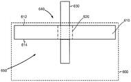
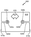
도 9는 본원에 기재된 특정 실시형태들에 따른 예시적인 전기 디바이스 (600) 를 개략적으로 예시한다. 전기 디바이스 (600) 는 (본원에 설명된 바처럼 무선 전력 전송 시스템 (100) 의 일부로서) 전력을 무선 송신 또는 무선 수신하도록 구성된다. 그러한 전기 디바이스 (600) 의 예들은, 무선 송신기 (예를 들어, 베이스 무선 충전 시스템 (302)), 무선 수신기 (예를 들어, 전기 차량 충전 시스템 (314)), 또는 양자 모두를 포함할 수 있다.9 schematically illustrates an exemplary
전기 디바이스 (600) 는, 적어도 하나의 오리피스 (620) (예를 들어, 홀, 개구, 강자성 재료 (610) 를 포함하지 않는 영역) 를 포함하는 강자성 재료 (610) 를 포함한다. 전기 디바이스 (600) 는 강자성 재료 (610) 의 적어도 하나의 오리피스 (620) 를 통해 연장되는 적어도 하나의 전기 도관 (630) (예를 들어, 전기 케이블, 전선, 피드스루) 를 더 포함한다. 예를 들어, 적어도 하나의 전기 도관 (630) 은, 강자성 재료 (610) 의 제 1 측 (612) 의 제 1 영역 (640) 으로부터 강자성 재료 (610) 의 제 2 측 (614) 의 제 2 영역 (650) 으로 연장할 수 있으며, 제 2 측 (614) 은 제 1 측 (612) 에 반대된다 (예를 들어, 제 1 영역 (640) 은 전기 디바이스 (600) 밖에 있을 수 있고 제 2 영역 (650) 은 전기 디바이스 (600) 내부에 있을 수 있다). 적어도 하나의 전기 도관 (630) 은, 제 1 영역 (640) 과 제 2 영역 (650) 사이에 적어도 하나의 전기 도관 (630) 을 따라 흐르는 적어도 하나의 교류를 갖도록 구성된다. 특정 실시형태들에서, 강자성 재료 (610) 및 적어도 하나의 전기 도관 (630) 은, 적어도 하나의 전기 도관 (630) 을 따라 흐르는 적어도 하나의 교류에 의해 강자성 재료 (610) 내에 생성된 주변 자속 밀도에 기인한 전력 손실을 감소 (예를 들어, 회피, 방지, 최소화) 시키도록 구성된다. 아래에서 더 상세하게 설명되는 바처럼, 다양한 구성들은 주변 자속 밀도에 기인한 전력 손실을 감소 (예를 들어, 회피, 방지, 최소화) 시키는데 사용될 수도 있다. 교류 흐름에 의해 생성된 와전류에 대한 주변 자속 밀도의 상이한 방향들에 기인하여, 이들 구성들은, 와전류 손실을 감소시키도록 설계된 구성들과는 상이하다.The
특정 실시형태들에서, 적어도 하나의 오리피스 (620) 는 에어 갭을 포함한다 (예를 들어, 적어도 하나의 전기 도관 (630) 을 제외하고는 고체 재료를 포함하지 않는다). 특정 다른 실시형태들에서, 적어도 하나의 오리피스 (620) 는, 재료 (예를 들어, 비강자성 재료, 이들의 예들은 플라스틱, 세라믹, 도전성 그러나 비강자성 금속, 합금, 또는 다른 고체 재료들을 포함하지만, 이에 한정되지는 않는다) 를 통해 흐르는 자속을 지원하지 않는 재료를 포함한다. 특정 실시형태들에서, 적어도 하나의 오리피스 (620) 는, 그렇지 않으면 강자성 재료 (610) 에서 형성되는 원하지 않는 자속을 차단함으로써, 적어도 하나의 전기 도관 (630) 을 따라 흐르는 적어도 하나의 교류에 의해 강자성 재료 (610) 내의 주변 자속에 기인한 전력 손실을 감소 (예를 들어, 회피, 방지, 최소화) 하도록 구성된다. 예를 들어, 적어도 하나의 오리피스 (620) 및 적어도 하나의 전기 도관 (630) 은 강자성 재료 (610) (예를 들어, 페라이트 플레이트) 의 평면 내에서 주변 자속 밀도를 차단하도록 구성될 수 있다. 대조적으로, 와전류 손실을 감소시키도록 설계된 구성은, 전기 도관 (630) 에 근접하여 도전성 재료에서 전기 도관 (630) 에 평행인 방향 (예를 들어, 전기 도관 (630) 이 연장되는 도전성 플레이트에 수직인 방향) 에서 와전류 흐름을 차단하도록 설계된다. In certain embodiments, at least one
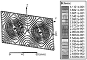
도 10은 페라이트 플레이트 (660) 가 강자성 재료 (610) 및 적어도 하나의 오리피스 (620) 를 포함하는 예시적인 시뮬레이션의 자속 밀도를 예시한다. 적어도 하나의 오리피스 (620) 는 한쌍의 홀들 (620a, 620b) 을 포함하고, 이들 각각은 그를 통해 전기 도관 (630) 이 연장된다 (전기 도관들 (630) 은 도 10에 도시되어 있지 않다). 적어도 하나의 오리피스 (620) 는, 강자성 재료 (610) 를 포함하지 않는 영역 (620c) 을 더 포함한다 (예를 들어, 페라이트 플레이트 (660) 의 슬라이스가 강자성 재료 (610) 없이 형성되거나 또는 그로부터 강자성 재료 (610) 가 제거되었다). 도 10의 슬라이스는 예시적인 폭이 1 mm 이고 하나의 홀 (620a) 로부터 다른 홀 (620b) 로 연장된다. 그러한 구조에서, 2개의 홀들 (620a, 620b) 더하기 영역 (620c) (예를 들어, 슬라이스) 는 페라이트 플레이트 (660) 를 통해 인접한, 단일의 오리피스 (620) 를 형성한다. 아래에서 더 상세하게 설명되는 바처럼, 그러한 구조는 본원에 설명된 특정 실시형태들을 따른다. 도 10 에 나타낸 예시적인 시뮬레이션은, 2개의 전기 도관들 (630) 을 통해 흐르는 교류에 의해 생성되는 페라이트 플레이트 (660) 에서 주변 자속 밀도를 보여준다. 이 모델 구조에서 생기는 전력 손실의 예시적인 양은 0.03 W 인 것으로 (예를 들어, Steinmetz 모델을 이용하여) 계산될 수 있다. 10 illustrates the magnetic flux density of an exemplary simulation in which the
도 11a 내지 도 11d 는 본원에 기재된 특정 실시형태들에 따른 전자 디바이스 (600) 의 예시적인 부분들을 개략적으로 예시한다. 도 11a 내지 도 11d 의 각각에 있는 양두 화살표는 강자성 재료 (610) 에서 주된 자속 방향 (670) (예를 들어, 디바이스의 기술적 목적을 위해 사용되는 자속의 방향) 을 나타낸다. 예를 들어, 주된 자속은, 강자성 재료 (610) 를 통해 전기 도관들 (630a, 630b) 을 따라 흐르는 교류에 의해 생성된 원하지 않는 주변 자속과는 상이한, 유도 전력 전송 (예를 들어, WEVC 동작) 에 사용되는 자속일 수 있다. 특정 실시형태들에서, 전기 도관들 (630a, 630b) 및 적어도 하나의 오리피스 (620) 는, 적어도 하나의 전기 도관들 (630) 을 따라 흐르는 적어도 하나의 교류에 의해 강자성 재료 (610) 내에 생성되는 주변 자속을 차단하면서 강자성 재료 (610) 에서 주된 자속 (예를 들어, 무선 전력 전송에서 사용되는 주된 자속) 의 단절을 감소 (예를 들어, 방지, 회피, 최소화) 시키도록 구성된다. 11A-11D schematically illustrate exemplary portions of an
예를 들어, 도 11a 내지 도 11d 에 도시된 바처럼, 전기 도관들 (630a, 630b) 및 전기 도관들 (630a, 630b) 사이의 적어도 하나의 오리피스 (620) 의 부분들 (예를 들어, 도 11b 의 부분 (620c)) 및/또는 전기 도관들 (630a, 630b) 중 하나와 강자성 재료 (610) 의 에지 (616) 사이 부분들 (예를 들어, 도 11c 의 부분들 (620d, 620e) 및 도 11d 의 부분 (620f)) 은 주된 자속 방향 (670) (예를 들어, 강자성 재료 (610) 를 이용하여 무선 전력 전송에서 사용되는 자속의 방향) 과 정렬될 수 있다. 대안적으로, 적어도 하나의 오리피스 (620) 가, 주된 자속이 (예를 들어, 디바이스 (600) 의 동작에 뚜렷하게 기여하지 않는 강자성 재료 (610) 의 부분들에서) 미미하게 영향받는 것으로 예상되는, 강자성 재료 (610) 의 부분들에서 형성될 수 있다. 그러한 부분들에서, 적어도 하나의 오리피스 (620) 가 주된 자속 방향 (670) 에 수직으로 연장되는 경우에도, 송신과 수신 코일들 사이의 자기 커플링의 감소에 기인한 무선 전력 전송 성능에 지나치게 영향을 미치지 않고서, 강자성 재료 (610) 에서의 전력 손실 감소가 실현될 것이다. For example, portions of at least one
도 11a 에서, 제 1 전기 도관 (630a) (예를 들어, 입력 전기 케이블) 이 강자성 재료 (610) 를 통해 (예를 들어, 강자성 재료 (610) 의 제 1 측 (612) 의 제 1 영역 (640) 으로부터, 강자성 재료 (610) 의 제 1 측 (612) 과 반대인 제 2 측 (614) 의 제 2 영역 (650) 으로) 연장되고 제 2 전기 도관 (630b) (예를 들어, 출력 전기 케이블) 이 강자성 재료 (610) 를 통해 (예를 들어, 강자성 재료 (610) 의 제 1 측 (612) 의 제 1 영역 (640) 으로부터 강자성 재료 (610) 의 제 2 측 (614) 의 제 2 영역 (650) 으로) 연장된다. 예를 들어, 제 1 영역 (640) 은 전기 디바이스 (600) 밖에 있을 수 있고 제 2 영역 (650) 은 전기 디바이스 (600) 내에 있을 수 있다. 제 1 전기 도관 (630a) 은 제 1 영역 (640) 으로부터 제 2 영역 (650) 으로 흐르는 제 1 교류를 전달하고 제 2 전기 도관은 제 2 영역 (650) 으로부터 제 1 영역 (640) 으로 흐르는 제 2 교류를 전달한다. 예를 들어, 제 1 교류 및 제 2 교류는 양자 모두 서로 반대되는 위상을 가질 수 있고 양자 모두 동일한 크기를 가질 수 있다. 강자성 재료 (610) 는, 제 1 및 제 2 전기 도관 (630a, 630b) 의 직경들의 합보다 더 크고 강자성 재료 (610) 의 제 1 측 (612) 으로부터 강자성 재료 (610) 의 제 2 측 (614) 으로 연장되는 오리피스 (620) (예를 들어, 홀, 개구, 강자성 재료 (610) 를 포함하지 않는 영역) 를 포함한다. 예를 들어, 도 11a 에서의 오리피스 (620) 는 일반적으로 직사각형 및 단일 형태이고, 제 1 및 제 2 전기 도관들 (630a, 630b) 양자 모두가 오리피스 (620) 안에 들어갈 정도로 충분히 크다. 원형, 난형, 정사각형, 삼각형, 및 불규칙형을 포함하지만 이에 한정되지는 않는, 오리피스 (620) 의 다른 형태들이 또한, 본원에 설명된 특정 실시형태들에 적합하다. 도 11a 의 구성에서, 제 1 및 제 2 전기 도관들 (630a, 630b) 로부터 강자성 재료 (610) 에 생성된 자속으로의 기여들은 (예를 들어, 제 1 및 제 2 교류가 동일한 크기 및 반대 위상을 가질 때, 완전히) 서로 상쇄됨으로써, 제 1 및 제 2 전기 도관들 (630a, 630b) 이 주변 자속을 차단하도록 구성되지 않는 분리된 오리피스들에 있는 구성들과 비교하여 주변 자속에 기인한 전력 손실을 감소 (예를 들어, 회피, 방지, 최소화) 시킨다. 11A, a first
다른 예로, 도 11b 에 개략적으로 도시된 바처럼, 오리피스 (620) 는, 각각 제 1 전기 도관 (630a) 및 제 2 전기 도관 (630b) 중 하나를 포함하는 2개의 제 1 부분들 (620a, 620b) (예를 들어, 2개의 대체로 원형인 부분들), 및 2개 제 1 부분들 (620a, 620b) 사이에서 연장되는 제 2 부분 (620c) (예를 들어, 대체로 직선형 부분) 에 의해 형성되는 인접한, 단일형 오리피스 (예를 들어, 홀, 개구, 강자성 재료 (610) 를 포함하지 않는 영역) 를 포함할 수 있다. 오리피스 (620) 의 제 2 부분 (620c) 은 주된 자속 방향 (670) 에 대체로 평행한 방향으로 연장될 수 있고, 다양한 기법들 (예를 들어, 강자성 재료 (610) 에서 슬라이스의 커팅, 비강자성 재료에 의해 함께 커플링될 수 있는, 강자성 재료 (610) 의 상이한 타일들의 조립) 에 의해 형성될 수 있다. 도 10의 오리피스 (620) 는 도 11b 에 개략적으로 예시된 부류의 오리피스들의 일 멤버이다. 오리피스 (620) 의 제 2 부분 (620c) 은, 각 전기 도관 (630a, 630b) 주위 자기 경로를 차단하여 자기 경로가 다른 전기 도관을 둘러싸지 않고서 단일 전기 도관을 완전히 둘러싸는 것을 방지할 수 있다. 이런 식으로, 양자 모두의 전기 도관들 (630a, 630b) 의 자기장들은 서로 상쇄되어, 추가 자속이 강자성 재료 (610) 에 발생되지 않음으로써, 강자성 재료 (610) 에서 주변 자속에 기인한 전력 손실을 감소시킬 수 있다. 오리피스 (620) 의 제 2 부분 (620c) 은 표준 페라이트 블록들을 조립하고 전기 도관들 (630a, 630b) 사이에 에어 갭 또는 비강자성 재료를 남기는 것에 의해 또는 단일 페라이트 구조에서 오리피스 (620) 의 제 2 부분 (620c) 을 기계가공하는 것에 의해 형성될 수 있다. 도 11a 의 오리피스 (620) 및 도 11b 의 오리피스 (620) 양자 모두는, 제 1 전기 도관 (630a) 및 제 2 전기 도관 (630b) 양자 모두를 포함하는 인접한, 단일형 오리피스 (620) 인 공통된 속성을 갖는다. 11b, the
도 11c 에서, 제 1 전기 도관 (630a) 이 강자성 재료 (610) 를 통해 (예를 들어, 강자성 재료 (610) 의 제 1 측 (612) 의 제 1 영역 (640) 으로부터 강자성 재료 (610) 의 제 1 측 (612) 과 반대인 제 2 측 (614) 의 제 2 영역 (650) 으로) 연장되고 제 2 전기 도관 (630b) 이 강자성 재료 (610) 를 통해 (예를 들어, 강자성 재료 (610) 의 제 1 측 (612) 의 제 1 영역 (640) 으로부터 강자성 재료 (610) 의 제 2 측 (614) 의 제 2 영역 (650) 으로) 연장된다. 제 1 전기 도관 (630a) 은 제 1 영역 (640) 으로부터 제 2 영역 (650) 으로 흐르는 제 1 교류를 전달하고 제 2 전기 도관 (630b) 은 제 2 영역 (650) 으로부터 제 1 영역 (640) 으로 흐르는 제 2 교류를 전달한다. 예를 들어, 제 1 교류 및 제 2 교류는 양자 모두 서로 반대되는 위상을 가질 수 있고 동일한 크기를 가질 수 있다. 강자성 재료 (610) 는, 제 1 전기 도관 (630a) 을 포함하는 제 1 오리피스 (620a, 620d) (예를 들어, 홀, 개구, 강자성 재료 (610) 를 포함하지 않는 영역) 및 제 2 전기 도관 (630b) 을 포함하는 제 2 오리피스 (620b, 620e) (예를 들어, 홀, 개구, 강자성 재료 (610) 를 포함하지 않는 영역) 을 포함한다. 제 1 오리피스 (620a, 620d) 및 제 2 오리피스 (620b, 620e) 의 각각은 강자성 재료 (610) 의 제 1 측 (612) 으로부터 강자성 재료 (610) 의 제 2 측 (614) 으로 연장되고, 제 1 오리피스 (620a, 620d) 및 제 2 오리피스 (620b, 620e) 의 각각은 오리피스 (620) 에 포함된 전기 도관 (630) 과 강자성 재료 (610) 의 에지 (616) 사이에서 강자성 재료 (610) 를 가로질러 연장된다 (예를 들어, 강자성 재료 (610) 의 외부 에지와 전기 도관을 포함하는 홀 사이의 슬라이스).In Figure 11c a first
예를 들어, 도 11c 에 개략적으로 예시된 바처럼, 제 1 오리피스 (620a, 620d) 는, 제 1 전기 도관 (630a) 을 포함하는 제 1 부분 (620a) 및 제 1 부분 (620a) 으로부터 강자성 재료의 제 1 에지 (616a) 로 연장되는 제 2 부분 (620d) 을 포함한다. 제 1 오리피스 (620a, 620d) 의 제 2 부분 (620d) 은 주된 자속 방향 (670) 에 대체로 평행한 방향으로 연장될 수 있다. 제 2 오리피스 (620b, 620e) 는, 제 2 전기 도관 (630b) 을 포함하는 제 1 부분 (620b) 및 강자성 재료 (610) 의 제 2 에지 (616b) 로 연장되는 제 2 부분 (620e) 을 포함한다. 제 2 오리피스 (620b, 620e) 의 제 2 부분 (620e) 은 주된 자속 방향 (670) 에 대체로 평행한 방향으로 연장될 수 있다. 특정 실시형태들에서, 제 1 에지 (616a) 및 제 2 에지 (616b) 는 서로 상이하다 (예를 들어, 강자성 재료 (610) 의 반대 에지들이다). 제 1 오리피스 (620a, 620d) 의 제 2 부분 (620d) 및/또는 제 2 오리피스 (620b, 620e) 의 제 2 부분 (620e) 은, 표준 페라이트 블록들을 조립하고 전기 도관들 (630) 과 에지들 (616a, 616b) 사이에 에어 갭 또는 비강자성 재료를 남기는 것에 의해 또는, 제 1 오리피스 (620a, 620d) 의 제 2 부분 (620d) 및/또는 제 2 오리피스 (620b, 620e) 의 제 2 부분 (620e) 을 단일 페라이트 구조에서 기계가공하는 것에 의해 형성될 수 있다.For example, as schematically illustrated in FIG. 11C,
도 11d 에서, 제 1 전기 도관 (630A) 이 강자성 재료 (610) 를 통해 (예를 들어, 강자성 재료 (610) 의 제 1 측 (612) 의 제 1 영역 (640) 으로부터 강자성 재료 (610) 의 제 1 측 (612) 과 반대인 제 2 측 (614) 의 제 2 영역 (650) 으로) 연장되고 제 2 전기 도관 (630b) 은 강자성 재료 (610) 를 통해 연장되지 않지만 (예를 들어, 강자성 재료 (610) 를 횡단하지 않지만), 강자성 재료 (610) 의 제 1 측 (612) 의 제 1 영역 (640) 으로부터 강자성 재료 (610) 의 제 2 측 (614) 의 제 2 영역 (650) 으로 연장된다. 제 1 전기 도관 (630a) 은 제 1 영역 (640) 으로부터 제 2 영역 (650) 으로 흐르는 제 1 교류를 전달하고 제 2 전기 도관 (630b) 은 제 2 영역 (650) 으로부터 제 1 영역 (640) 으로 흐르는 제 2 교류를 전달한다. 예를 들어, 제 1 교류 및 제 2 교류는 양자 모두 서로 반대되는 위상을 가질 수 있고 동일한 크기를 가질 수 있다. 강자성 재료 (610) 는 제 1 전기 도관 (630a) 을 포함하는 오리피스 (620a, 620f) 를 포함한다. 오리피스 (620a, 620f) 는 강자성 재료 (610) 의 제 1 측 (612) 으로부터 강자성 재료 (610) 의 제 2 측 (614) 으로 연장된다. 오리피스 (620a, 620f) 는 제 1 전기 도관 (630a) 과 강자성 재료 (610) 의 에지 (616) 사이에서 강자성 재료 (610) 를 가로질러 연장된다. In Figure 11d a first electrical conduit 630A extends from the
예를 들어, 도 11d 에 개략적으로 예시된 바처럼, 오리피스 (620a, 620f) 는, 제 1 전기 도관 (630a) 을 포함하는 제 1 부분 (620a) 및 제 1 부분 (620a) 으로부터 강자성 재료 (610) 의 에지 (616) 로 연장되는 제 2 부분 (620f) 을 포함한다. 오리피스 (620a, 620f) 의 제 2 부분 (620f) 은 주된 자속 방향 (670) 에 대체로 평행한 방향으로 연장될 수 있다. 오리피스 (620a, 620f) 의 제 2 부분 (620f) 은, 표준 페라이트 블록들을 조립하고 전기 도관 (620) 과 에지 (616) 사이에 에어 갭 또는 비강자성 재료를 남기는 것에 의해 또는 단일 페라이트 구조에서 오리피스 (620a, 620f) 의 제 2 부분 (620f) 을 기계가공하는 것에 의해 형성될 수 있다. For example,
도 11c 의 제 1 전기 도관 (630a) 을 포함하는 제 1 오리피스 (620a, 620d), 도 11c 의 제 2 전기 도관 (630b) 을 포함하는 제 2 오리피스 (620b, 620e), 및 도 11d 의 제 1 전기 도관 (630a) 을 포함하는 오리피스 (620a, 620f) 는 모두, 강자성 재료 (610) 가 거기에 포함된 전기 도관 (630) 을 완전히 둘러싸지 않도록 구성되는 동일한 속성을 공유한다. 이 속성은, 강자성 재료 (610) 의 외부에 전기 도관 (630) 을 갖는 것과 유사한 것으로 (예를 들어, 강자성 재료 (610) 의 외부에 도 11d 의 제 2 전기 도관 (630b) 을 배치하는 것에 유사한 것으로) 볼 수 있다.The
도 12는 간략화된 구조를 위한 등가 자기 회로 계산을 개략적으로 예시한다. 도 12의 우측은 전기 도관 (630) (미도시) 이 (음영의 원으로 표기되는) 강자성 재료 (610) 를 통하여 (백색 중심 원으로 표시되는) 오리피스 (620) 를 통해 연장되는 단순화된 구조를 보여준다. 전기 도관 (630) 을 통해 흐르는 교류는 (화살표로 표기되는) 강자성 재료 (610) 내부에 자속 ![]()
![]()
Steinmetz 모델에 따르면, 강자성 (예를 들어, 페라이트) 재료 (610) 에서의 손실은 2 내지 3 범위의 거듭제곱으로 상승된 자속 밀도에 비례한다. 이렇게 하여, 자속 밀도를 5배 만큼 감소시킴으로써, 손실들은 적어도 25배 만큼 감소될 수 있다. 게다가, 자속 ![]()
![]()
예를 들어, 오리피스 (620) 의 수정이 강자성 재료 (610) 를 통한 슬라이스의 추가를 포함하는 경우, 다음 등식이 슬라이스의 폭 (l slice ) 을 선택하는데 유익할 수 있다:For example, if a modification of
![]()
![]()
이 등식은 l slice = 0.004 * l ferrite 를 나타내도록 줄여질 수 있다. r mean = 25 mm 를 가정하면, 적어도 25배 만큼 손실의 감소를 낳는 슬라이스의 폭 (l slice ) 은 0.63 mm 일 수 있다. 실제로 비선형 필드 거동에 기인하여, 훨씬 더 작은 폭들의 슬라이스들은 리럭턴스에서의 원하는 증가 및 손실에서의 수반되는 감소를 달성할 수 있다. This equation can be reduced to represent l slice = 0.004 * l ferrite . r assuming the mean = 25 mm, the width (l slice) of a slice lays a reduction in the loss of at least 25 times as much as may be 0.63 mm. Due to virtually nonlinear field behavior, slices of much smaller widths can achieve the desired increase in reluctance and concomitant reduction in loss.
도 13은 본원에 기재된 특정 실시형태들에 따른 전력을 무선 송신 또는 무선 수신하는 예시적인 방법의 흐름도 (700) 이다. 동작 블록 (710) 에서, 방법 (700) 은 무선 전력 전송 시스템의 전기 디바이스 (600) 를 제공하는 단계를 포함한다. 디바이스 (600) 는, 강자성 재료 (610) 및 그 강자성 재료 (610) 를 통해 연장되는 적어도 하나의 오리피스 (620) 를 포함한다. 동작 블록 (720) 에서, 그 방법 (700) 은, 강자성 재료 (610) 의 제 1 측 (612) 의 제 1 영역 (640) 으로부터 상기 강자성 재료 (610) 의 제 2 측 (614) 의 제 2 영역 (650) 으로 적어도 하나의 오리피스 (620) 를 통해 교류 전류를 전도시키는 단계를 더 포함한다. 제 2 측 (614) 은 제 1 측 (612) 과 반대이다. 강자성 재료 (610) 및 적어도 하나의 오리피스 (620) 는, 교류 전류에 의해 강자성 재료 (610) 내에 생성된 주변 자속에 의해 야기되는 강자성 재료 (610) 내 전력 손실을 감소시키도록 구성된다. 13 is a
도 14는, 무선 전력 전송 시스템의 일부로서 전력을 무선 송신 또는 무선 수신하도록 구성된 전기 디바이스 (600) 를 제조하는 예시적인 방법 (800) 의 흐름도이다. 동작 블록 (810) 에서, 방법 (800) 은 적어도 하나의 오리피스 (620) 를 포함하는 강자성 재료 (610) 를 제공하는 단계를 포함한다. 동작 블록 (820) 에서, 그 방법 (800) 은, 강자성 재료 (610) 의 제 1 측 (612) 의 제 1 영역 (640) 으로부터 상기 강자성 재료 (610) 의 제 2 측 (614) 의 제 2 영역 (650) 으로 강자성 재료 (610) 의 적어도 하나의 오리피스 (620) 를 통해 적어도 하나의 전기 도관 (630) 을 연장시키는 단계를 더 포함한다. 제 2 측 (614) 은 제 1 측 (612) 과 반대이다. 적어도 하나의 전기 도관 (630) 은, 제 1 영역 (640) 과 제 2 영역 (650) 사이에 적어도 하나의 전기 도관 (630) 을 따라 흐르는 적어도 하나의 교류를 갖도록 구성된다. 강자성 재료 (610) 및 적어도 하나의 전기 도관 (630) 은, 적어도 하나의 전기 도관 (630) 을 따라 흐르는 적어도 하나의 교류에 의해 강자성 재료 (610) 내에 생성된 주변 자속에 의해 야기되는 강자성 재료 (610) 내 전력 손실을 감소시키도록 구성된다.14 is a flow diagram of an
예를 들어, 강자성 재료 (610) 를 제공하는 단계는 강자성 재료 (610) 의 일 부분에서 적어도 하나의 오리피스 (620) 를 커팅하는 단계를 포함할 수 있다. 다른 예로, 강자성 재료를 제공하는 단계는, 강자성 재료 (610) 의 타일들을 조립하고 비강자성 재료에 의해 함께 타일들을 기계적으로 커플링하는 단계를 포함할 수 있다. 특정 실시형태들에서, 적어도 하나의 오리피스 (620) 는 비강자성 재료를 포함한다.For example, providing the
전술된 방법들의 다양한 동작들은, 다양한 하드웨어 및/또는 소프트웨어 컴포넌트(들), 회로들 및/또는 모듈(들) 과 같은, 그 동작들을 수행할 수 있는 임의의 적합한 수단에 의해 수행될 수도 있다. 일반적으로, 도면들에 예시된 임의의 동작들은 그 동작들을 수행할 수 있는 대응하는 기능 수단에 의해 수행될 수도 있다. 예를 들어, 전력을 무선 송신하는 수단은 무선 전력 송신기를 포함할 수도 있고, 전력을 무선 수신하는 수단은 무선 전력 수신기를 포함할 수도 있다. 또한, 자속을 채널링하는 수단은 강자성 재료를 포함할 수도 있다. 또한, 교류 전류를 전도시키는 수단은 전기 도관을 포함할 수도 있다. 정보 및 신호들은 임의의 다양한 상이한 기술 및 기법을 이용하여 표현될 수도 있다. 예를 들어, 위의 설명 전체에 걸쳐 언급될 수도 있는 데이터, 명령, 커맨드, 정보, 신호, 비트, 심볼, 및 칩은 전압, 전류, 전자기파, 자기장 또는 자기입자, 광학장 (optical field) 또는 광학 입자, 또는 이들의 임의의 조합에 의해 표현될 수도 있다.The various operations of the above-described methods may be performed by any suitable means capable of performing the operations, such as various hardware and / or software component (s), circuits and / or module (s). In general, any of the operations illustrated in the figures may be performed by corresponding functional means capable of performing the operations. For example, the means for wirelessly transmitting power may comprise a wireless power transmitter, and the means for wirelessly receiving power may comprise a wireless power receiver. The means for channeling the magnetic flux may also comprise a ferromagnetic material. The means for conducting the alternating current may also include an electrical conduit. The information and signals may be represented using any of a variety of different techniques and techniques. For example, data, instructions, commands, information, signals, bits, symbols, and chips that may be referenced throughout the above description may be represented by voltages, currents, electromagnetic waves, magnetic fields or particles, Particles, or any combination thereof.
여기에 개시된 실시형태들과 관련하여 설명된 다양한 예시적인 논리 블록, 모듈, 회로, 및 알고리즘 단계들이 전자 하드웨어, 컴퓨터 소프트웨어, 또는 이 양자의 조합으로 구현될 수도 있다. 하드웨어와 소프트웨어의 이러한 상호교환가능성을 명확히 예시하기 위해, 다양한 예시적인 컴포넌트, 블록, 모듈, 회로, 및 단계가 일반적으로 그들의 기능성의 측면에서 위에서 설명되었다. 그러한 기능이 하드웨어 또는 소프트웨어로 구현될지 여부는, 전체 시스템에 부과된 특정 응용 및 설계 제약에 달려 있다. 설명된 기능성은 특정 응용 각각에 대한 다양한 방식으로 구현될 수도 있지만, 이러한 구현 결정이 본 발명의 실시형태들의 범위를 벗어나게 하는 것으로 해석되지는 않아야 한다. The various illustrative logical blocks, modules, circuits, and algorithm steps described in connection with the embodiments disclosed herein may be implemented as electronic hardware, computer software, or combinations of both. In order to clearly illustrate this interchangeability of hardware and software, various illustrative components, blocks, modules, circuits, and steps have been described above generally in terms of their functionality. Whether such functionality is implemented as hardware or software depends upon the particular application and design constraints imposed on the overall system. The described functionality may be implemented in various ways for each particular application, but such implementation decisions should not be interpreted as causing a departure from the scope of embodiments of the present invention.
여기에 개시된 실시형태와 관련하여 설명된 다양한 예시적인 블록, 모듈, 및 회로는 범용 프로세서, 디지털 신호 프로세서 (DSP), 주문형 집적 회로 (ASIC), 필드 프로그래밍가능 게이트 어레이 (FPGA) 또는 다른 프로그래밍가능 로직 디바이스, 이산 게이트 또는 트랜지스터 로직, 이산 하드웨어 컴포넌트, 또는 여기에 설명된 기능을 수행하도록 설계된 이들의 임의의 조합으로 구현 또는 수행될 수도 있다. 범용 프로세서는 마이크로프로세서일 수도 있지만, 다르게는, 프로세서는 임의의 종래의 프로세서, 제어기, 마이크로제어기, 또는 상태 머신일 수도 있다. 또한, 프로세서는 컴퓨팅 디바이스들의 조합, 예를 들어, DSP 와 마이크로프로세서의 조합, 복수의 마이크로프로세서, DSP 코어와 결합한 하나 이상의 마이크로프로세서, 또는 임의의 다른 이러한 구성으로서 구현될 수도 있다. The various illustrative blocks, modules, and circuits described in connection with the embodiments disclosed herein may be implemented or performed with a general purpose processor, a digital signal processor (DSP), an application specific integrated circuit (ASIC), a field programmable gate array Discrete gate or transistor logic, discrete hardware components, or any combination thereof designed to perform the functions described herein. A general purpose processor may be a microprocessor, but, in the alternative, the processor may be any conventional processor, controller, microcontroller, or state machine. The processor may also be implemented as a combination of computing devices, e.g., a combination of a DSP and a microprocessor, a plurality of microprocessors, one or more microprocessors in conjunction with a DSP core, or any other such configuration.
여기에 개시된 실시형태와 관련하여 설명된 방법 또는 알고리즘의 단계들 및 기능들은 직접 하드웨어로, 프로세서에 의해 실행되는 소프트웨어 모듈로, 또는 그들의 조합으로 구체화될 수도 있다. 소프트웨어로 구현되면, 그 기능들은 유형의 비일시적 컴퓨터 판독가능 매체 상의 하나 이상의 명령 또는 코드로서 저장되거나 송신될 수도 있다. 소프트웨어 모듈은 랜덤 액세스 메모리 (RAM), 플래시 메모리, 판독 전용 메모리 (ROM), 전기적으로 프로그램가능 ROM (EPROM), 전기적으로 소거가능한 프로그램가능 ROM (EEPROM), 레지스터, 하드디스크, 리무버블 디스크, CD ROM, 또는 업계에 공지된 임의의 다른 형태의 저장 매체에 상주할 수도 있다. 저장 매체는 프로세서가 저장 매체로부터 정보를 판독할 수 있고 저장 매체에 정보를 기입할 수 있도록 프로세서에 연결된다. 다르게는, 저장 매체는 프로세서에 내장될 수도 있다. 여기에 설명된 바와 같이, 디스크 (disk) 및 디스크 (disc) 는 콤팩트 디스크 (CD), 레이저 디스크, 광 디스크, DVD (digital versatile disc), 플로피 디스크 및 블루레이 디스크를 포함하며, 여기서, 디스크 (disk) 는 일반적으로 데이터를 자기적으로 재생하지만, 디스크 (disc) 는 레이저를 이용하여 광학적으로 데이터를 재생한다. 또한, 앞서 말한 것의 조합이 컴퓨터 판독가능 매체의 범위 내에 포함되어야 한다. 프로세서 및 저장 매체는 ASIC 에 상주할 수도 있다.The steps and functions of the method or algorithm described in connection with the embodiments disclosed herein may be embodied directly in hardware, in a software module executed by a processor, or in a combination of the two. When implemented in software, the functions may be stored or transmitted as one or more instructions or code on a type of non-volatile computer readable medium. The software module may be a random access memory (RAM), a flash memory, a read only memory (ROM), an electrically programmable ROM (EPROM), an electrically erasable programmable ROM (EEPROM), a register, a hard disk, ROM, or any other form of storage medium known in the art. A storage medium is coupled to the processor such that the processor can read information from, and write information to, the storage medium. Alternatively, the storage medium may be embedded in the processor. As described herein, a disk and a disc may include a compact disk (CD), a laser disk, an optical disk, a digital versatile disk (DVD), a floppy disk and a Blu-ray disk, disk generally reproduces data magnetically, while discs reproduce data optically using a laser. Also, combinations of the foregoing should be included within the scope of computer readable media. The processor and the storage medium may reside in an ASIC.
본 개시를 요약하는 목적으로, 본 발명의 특정 양태들, 이점들 및 신규한 특징들이 여기에서 설명되었다. 모든 그러한 이점들이 반드시 본 발명의 임의의 특정 실시형태에 따라 달성되는 것은 아닐 수도 있다는 것이 이해되야 한다. 따라서, 본 발명은, 여기에 교시되거나 또는 시사될 수도 있는 바처럼 반드시 다른 이점들을 달성하는 것은 아닌 여기에 교시된 바처럼 하나의 이점 또는 집단의 이점들을 달성하거나 또는 최적화하는 방식으로 구체화되거나 또는 수행될 수도 있다.For purposes of summarizing the disclosure, certain aspects, advantages, and novel features of the invention have been described herein. It is to be understood that not all such advantages may be achieved in accordance with any particular embodiment of the present invention. Accordingly, the present invention may be embodied or performed in a manner that accomplishes or optimizes one advantage or group of benefits, as taught herein, rather than necessarily achieving other benefits, such as may be taught or suggested herein .
전술된 실시형태들의 다양한 수정들이 손쉽게 분명해질 것이고, 여기에 정의된 일반 원리들은, 본 발명의 사상 또는 범위를 벗어남이 없이 다른 실시형태에 적용될 수도 있다. 따라서, 본 발명은 여기에 나타낸 실시형태로 한정되도록 의도된 것이 아니라, 여기에 개시된 원리 및 신규한 특징들에 부합하는 최광의 범위가 허여되야 한다.Various modifications of the above-described embodiments will be readily apparent, and the generic principles defined herein may be applied to other embodiments without departing from the spirit or scope of the invention. Accordingly, the invention is not intended to be limited to the embodiments shown herein but is to be accorded the widest scope consistent with the principles and novel features disclosed herein.
Claims (30)
적어도 하나의 오리피스를 포함하는 강자성 재료;
상기 강자성 재료의 제 1 측의 제 1 영역으로부터 상기 강자성 재료의 제 2 측의 제 2 영역으로 상기 강자성 재료의 상기 적어도 하나의 오리피스를 통해 연장되는 적어도 하나의 전기 도관을 포함하고,
상기 제 2 측은 상기 제 1 측과 반대이고, 상기 적어도 하나의 전기 도관은 상기 제 1 영역과 상기 제 2 영역 사이의 상기 적어도 하나의 전기 도관을 따라 흐르는 적어도 하나의 교류를 갖도록 구성되고, 상기 강자성 재료 및 상기 적어도 하나의 전기 도관은 상기 적어도 하나의 전기 도관을 따라 흐르는 상기 적어도 하나의 교류에 의해 상기 강자성 재료 내에 생성되는 주변 자속에 의해 야기되는 상기 강자성 재료 내의 전력 손실을 감소시키도록 구성되는, 전기 디바이스.An electrical device configured to wirelessly transmit or wirelessly receive power as part of a wireless power transmission system,
A ferromagnetic material comprising at least one orifice;
At least one electrical conduit extending through the at least one orifice of the ferromagnetic material from a first region of the first side of the ferromagnetic material to a second region of the second side of the ferromagnetic material,
Wherein the second side is opposite to the first side and the at least one electrical conduit is configured to have at least one alternating current flowing along the at least one electrical conduit between the first region and the second region, Material and the at least one electrical conduit are configured to reduce power loss in the ferromagnetic material caused by the ambient flux generated in the ferromagnetic material by the at least one alternating current flowing along the at least one electrical conduit, Electrical device.
상기 전기 디바이스는 무선 송신기, 무선 수신기 또는 양자 모두를 포함하는, 전기 디바이스.The method according to claim 1,
Wherein the electrical device comprises a wireless transmitter, a wireless receiver, or both.
상기 적어도 하나의 오리피스는 에어 갭을 포함하는, 전기 디바이스.The method according to claim 1,
Wherein the at least one orifice comprises an air gap.
상기 적어도 하나의 오리피스는 비강자성 재료를 포함하는, 전기 디바이스.The method according to claim 1,
Wherein the at least one orifice comprises a non-ferromagnetic material.
상기 적어도 하나의 오리피스는, 상기 적어도 하나의 전기 도관을 따라 흐르는 상기 적어도 하나의 교류에 의해 상기 강자성 재료에서 생성된 주변 자속을 차단하도록 구성되는, 전기 디바이스.The method according to claim 1,
Wherein the at least one orifice is configured to block ambient flux generated in the ferromagnetic material by the at least one alternating current flowing along the at least one electrical conduit.
상기 적어도 하나의 전기 도관 및 상기 적어도 하나의 오리피스는, 상기 적어도 하나의 전기 도관을 따라 흐르는 상기 적어도 하나의 교류에 의해 생성된 상기 강자성 재료 내의 상기 주변 자속을 차단하면서 상기 강자성 재료에서 주된 자속의 단절을 감소시키도록 구성되는, 전기 디바이스.The method according to claim 1,
Wherein the at least one electrical conduit and the at least one orifice block the ambient flux in the ferromagnetic material generated by the at least one alternating current flowing along the at least one electrical conduit, Of the electrical device.
상기 적어도 하나의 오리피스의 적어도 하나의 부분은 상기 주된 자속 방향의 방향과 정렬되는, 전기 디바이스.The method according to claim 6,
Wherein at least one portion of the at least one orifice is aligned with a direction of the main flux direction.
상기 적어도 하나의 오리피스는, 전자 디바이스의 동작에 뚜렷하게 기여하지 않는 상기 강자성 재료의 일 부분에 형성되는, 전기 디바이스.The method according to claim 6,
Wherein the at least one orifice is formed in a portion of the ferromagnetic material that does not contribute significantly to the operation of the electronic device.
상기 적어도 하나의 전기 도관은,
상기 강자성 재료를 통해 상기 강자성 재료의 상기 제 1 측의 상기 제 1 영역으로부터 상기 강자성 재료의 상기 제 2 측의 상기 제 2 영역으로 연장하는 제 1 전기 도관으로서, 상기 제 1 전기 도관은 상기 제 1 영역으로부터 상기 제 2 영역으로 흐르는 제 1 교류를 전달하도록 구성되는, 상기 제 1 전기 도관; 및
상기 강자성 재료를 통해 상기 강자성 재료의 상기 제 1 측의 상기 제 1 영역으로부터 상기 강자성 재료의 상기 제 2 측의 상기 제 2 영역으로 연장하는 제 2 전기 도관으로서, 상기 제 2 전기 도관은 상기 제 2 영역으로부터 상기 제 1 영역으로 흐르는 제 2 교류를 전달하도록 구성되는, 상기 제 2 전기 도관을 포함하는, 전기 디바이스.The method according to claim 1,
Said at least one electrical conduit comprising:
A first electrical conduit extending from the first region of the first side of the ferromagnetic material through the ferromagnetic material to the second region of the second side of the ferromagnetic material, The first electrical conduit configured to transfer a first alternating current flowing from the region to the second region; And
A second electrical conduit extending from the first region of the first side of the ferromagnetic material through the ferromagnetic material to the second region of the second side of the ferromagnetic material, Wherein the second electrical conduit is configured to transfer a second alternating current flowing from the region to the first region.
상기 제 1 교류 및 상기 제 2 교류는 서로 반대되는 위상을 갖고 동일한 크기를 갖는, 전기 디바이스.10. The method of claim 9,
Wherein the first alternating current and the second alternating current have opposite phases and have the same magnitude.
상기 제 1 전기 도관 및 상기 제 2 전기 도관은 양자 모두 상기 적어도 하나의 오리피스의 인접한, 단일형 오리피스를 통해 연장되는, 전기 디바이스.10. The method of claim 9,
Wherein the first electrical conduit and the second electrical conduit both extend through adjacent, monolithic orifices of the at least one orifice.
상기 인접한, 단일형 오리피스는, 각각 상기 제 1 전기 도관 및 상기 제 2 전기 도관 중 하나를 포함하는 2개의 제 1 부분들 및 상기 2개의 제 1 부분들 사이에 연장되는 제 2 부분을 포함하는, 전기 디바이스.12. The method of claim 11,
Wherein the adjacent, monolithic orifice comprises two first portions comprising one of the first and second electrical conduits, respectively, and a second portion extending between the two first portions, device.
상기 오리피스의 상기 제 2 부분은 대체로 직선형이고 주된 자속 방향에 대체로 평행인 방향으로 연장되는, 전기 디바이스.13. The method of claim 12,
Wherein the second portion of the orifice extends in a direction that is generally straight and generally parallel to the main flux direction.
상기 적어도 하나의 오리피스는 상기 제 1 전기 도관을 포함하는 제 1 오리피스 및 상기 제 2 전기 도관을 포함하는 제 2 오리피스를 포함하고, 상기 제 1 오리피스 및 상기 제 2 오리피스의 각각은 그 안에 포함된 대응하는 전기 도관과 상기 강자성 재료의 에지 사이에서 상기 강자성 재료를 가로질러 연장되는, 전기 디바이스.10. The method of claim 9,
Wherein the at least one orifice comprises a first orifice comprising the first electrical conduit and a second orifice comprising the second electrical conduit, wherein each of the first orifice and the second orifice comprises a corresponding And extends across the ferromagnetic material between the electrical conduit and the edge of the ferromagnetic material.
상기 제 1 오리피스, 상기 제 2 오리피스, 또는 양자 모두는 상기 강자성 재료의 외부 에지와 상기 전기 도관 사이의 슬라이스를 포함하는, 전기 디바이스.15. The method of claim 14,
Wherein the first orifice, the second orifice, or both comprise a slice between the outer edge of the ferromagnetic material and the electrical conduit.
상기 제 1 오리피스는, 상기 제 1 전기 도관을 포함하는 제 1 부분 및 상기 제 1 부분으로부터 상기 강자성 재료의 제 1 에지로 연장되는 제 2 부분을 포함하는, 전기 디바이스.15. The method of claim 14,
Wherein the first orifice comprises a first portion comprising the first electrical conduit and a second portion extending from the first portion to a first edge of the ferromagnetic material.
상기 제 1 오리피스의 상기 제 2 부분은 주된 자속 방향에 대체로 평행인 방향으로 연장되는, 전기 디바이스.17. The method of claim 16,
And the second portion of the first orifice extends in a direction generally parallel to the main flux direction.
상기 제 2 오리피스는, 상기 제 2 전기 도관을 포함하는 제 1 부분 및 상기 강자성 재료의 제 2 에지로 연장되는 제 2 부분을 포함하는, 전기 디바이스.17. The method of claim 16,
Wherein the second orifice comprises a first portion comprising the second electrical conduit and a second portion extending to a second edge of the ferromagnetic material.
상기 제 2 오리피스의 상기 제 2 부분은 주된 자속 방향에 대체로 평행인 방향으로 연장되는, 전기 디바이스.19. The method of claim 18,
And the second portion of the second orifice extends in a direction generally parallel to the main flux direction.
상기 제 1 에지 및 상기 제 2 에지는 서로 상이한, 전기 디바이스.19. The method of claim 18,
Wherein the first edge and the second edge are different from each other.
상기 적어도 하나의 전기 도관은, 상기 강자성 재료를 통해 상기 강자성 재료의 상기 제 1 측의 상기 제 1 영역으로부터 상기 강자성 재료의 상기 제 2 측의 상기 제 2 영역으로 연장되는 제 1 전기 도관을 포함하고, 상기 제 2 측은 상기 제 1 측과 반대이고, 상기 제 1 전기 도관은 상기 제 1 영역으로부터 상기 제 2 영역으로 흐르는 제 1 교류 전류를 전달하도록 구성되고, 상기 전기 디바이스는 상기 강자성 재료를 통해 연장되지 않지만 상기 강자성 재료의 상기 제 1 측의 상기 제 1 영역으로부터 상기 강자성 재료의 상기 제 2 측의 상기 제 2 영역으로 연장되는 제 2 전기 도관을 포함하고, 상기 제 2 전기 도관은 상기 제 2 영역으로부터 상기 제 1 영역으로 흐르는 제 2 교류를 전달하도록 구성되는, 전기 디바이스.The method according to claim 1,
The at least one electrical conduit includes a first electrical conduit extending from the first region of the first side of the ferromagnetic material through the ferromagnetic material to the second region of the second side of the ferromagnetic material Wherein the second side is opposite to the first side and the first electrical conduit is configured to transfer a first alternating current flowing from the first region to the second region and the electrical device extends through the ferromagnetic material And a second electrical conduit extending from said first region of said first side of said ferromagnetic material to said second region of said second side of said ferromagnetic material, And a second current flowing from the first region to the first region.
상기 적어도 하나의 오리피스는, 상기 제 1 전기 도관을 포함하는 오리피스를 포함하고, 상기 오리피스는 상기 제 1 전기 도관과 상기 강자성 재료의 에지 사이에서 상기 강자성 재료를 가로질러 연장되는, 전기 디바이스.22. The method of claim 21,
Wherein the at least one orifice comprises an orifice comprising the first electrical conduit and the orifice extends across the ferromagnetic material between the first electrical conduit and the edge of the ferromagnetic material.
상기 오리피스는, 상기 제 1 전기 도관을 포함하는 제 1 부분 및 상기 제 1 부분으로부터 상기 강자성 재료의 에지로 연장되는 제 2 부분을 포함하는, 전기 디바이스.23. The method of claim 22,
Wherein the orifice comprises a first portion comprising the first electrical conduit and a second portion extending from the first portion to an edge of the ferromagnetic material.
상기 오리피스의 상기 제 2 부분은 주된 자속 방향에 대체로 평행인 방향으로 연장되는, 전기 디바이스.24. The method of claim 23,
And the second portion of the orifice extends in a direction generally parallel to the main flux direction.
강자성 재료를 통해 상기 강자성 재료의 제 1 측의 제 1 영역으로부터 상기 강자성 재료의 제 2 측의 제 2 영역으로 연장되는 적어도 하나의 오리피스를 통해 교류 전류를 전도시키는 단계로서, 상기 제 2 측은 상기 제 1 측과 반대이고, 상기 강자성 재료 및 상기 적어도 하나의 오리피스는 상기 교류 전류에 의해 상기 강자성 재료 내에 생성되는 주변 자속에 의해 야기되는 상기 강자성 재료 내의 전력 손실을 감소시키도록 구성되는, 상기 교류 전류를 전도시키는 단계; 및
상기 강자성 재료를 포함하는 디바이스를 통해 전력을 무선 송신 또는 무선 수신하는 단계
를 포함하는, 전력을 무선 송신 또는 무선 수신하는 방법.A method of wirelessly transmitting or wirelessly receiving power,
Conducting an alternating current through a ferromagnetic material through at least one orifice extending from a first region of the first side of the ferromagnetic material to a second region of the second side of the ferromagnetic material, 1, the ferromagnetic material and the at least one orifice being configured to reduce power loss in the ferromagnetic material caused by ambient magnetic flux generated in the ferromagnetic material by the alternating current, Conducting; And
Wirelessly transmitting or wirelessly receiving power through a device comprising the ferromagnetic material
Wherein the method comprises the steps of:
적어도 하나의 오리피스를 포함하는 강자성 재료를 제공하는 단계; 및
상기 강자성 재료의 제 1 측의 제 1 영역으로부터 상기 강자성 재료의 제 2 측의 제 2 영역으로 상기 강자성 재료의 상기 적어도 하나의 오리피스를 통해 적어도 하나의 전기 도관을 연장시키는 단계를 포함하고,
상기 제 2 측은 상기 제 1 측과 반대이고, 상기 적어도 하나의 전기 도관은 상기 제 1 영역과 상기 제 2 영역 사이의 상기 적어도 하나의 전기 도관을 따라 흐르는 적어도 하나의 교류를 갖도록 구성되고, 상기 강자성 재료 및 상기 적어도 하나의 전기 도관은 상기 적어도 하나의 전기 도관을 따라 흐르는 상기 적어도 하나의 교류에 의해 상기 강자성 재료 내에 생성되는 주변 자속에 의해 야기되는 상기 강자성 재료 내의 전력 손실을 감소시키도록 구성되는, 전기 디바이스의 제조 방법.A method of manufacturing an electrical device configured to wirelessly transmit or wirelessly receive power as part of a wireless power transmission system,
Providing a ferromagnetic material comprising at least one orifice; And
Extending at least one electrical conduit through the at least one orifice of the ferromagnetic material from a first region of the first side of the ferromagnetic material to a second region of the second side of the ferromagnetic material,
Wherein the second side is opposite to the first side and the at least one electrical conduit is configured to have at least one alternating current flowing along the at least one electrical conduit between the first region and the second region, Material and the at least one electrical conduit are configured to reduce power loss in the ferromagnetic material caused by the ambient flux generated in the ferromagnetic material by the at least one alternating current flowing along the at least one electrical conduit, A method of manufacturing an electrical device.
상기 강자성 재료를 제공하는 단계는 상기 강자성 재료의 일 부분에서 상기 적어도 하나의 오리피스를 커팅하는 단계를 포함하는, 전기 디바이스의 제조 방법.27. The method of claim 26,
Wherein providing the ferromagnetic material includes cutting the at least one orifice in a portion of the ferromagnetic material.
상기 강자성 재료를 제공하는 단계는, 상기 강자성 재료의 타일들을 조립하고 비강자성 재료에 의해 함께 상기 타일들을 기계적으로 커플링하는 단계를 포함하는, 전기 디바이스의 제조 방법.27. The method of claim 26,
Wherein providing the ferromagnetic material comprises assembling the tiles of the ferromagnetic material and mechanically coupling the tiles together by a non-ferromagnetic material.
상기 적어도 하나의 오리피스는 비강자성 재료를 포함하는, 전기 디바이스의 제조 방법.27. The method of claim 26,
Wherein the at least one orifice comprises a non-ferromagnetic material.
자속을 채널링하는 수단을 포함하는 전력을 무선 송신 또는 무선 수신하는 수단으로서, 상기 자속을 채널링하는 수단은 적어도 하나의 오리피스를 포함하는, 상기 전력을 무선 송신 또는 무선 수신하는 수단; 및
교류 전류를 전도시키는 수단을 포함하고, 상기 전도시키는 수단은 상기 자속을 채널링하는 수단의 제 1 측의 제 1 영역으로부터 상기 자속을 채널링하는 수단의 제 2 측의 제 2 영역으로 상기 자속을 채널링하는 수단의 상기 적어도 하나의 오리피스를 통하여 연장되고, 상기 제 2 측은 상기 제 1 측과 반대이고, 상기 전도시키는 수단은 상기 제 1 영역과 상기 제 2 영역 사이에서 상기 전도시키는 수단을 따라 흐르는 적어도 하나의 교류를 갖도록 구성되고, 상기 자속을 채널링하는 수단 및 상기 전도시키는 수단은 상기 전도시키는 수단을 따라 흐르는 상기 적어도 하나의 교류에 의해 상기 자속을 채널링하는 수단 내에 생성되는 주변 자속에 의해 야기되는 상기 자속을 채널링하는 수단 내의 전력 손실을 감소시키도록 구성되는, 전기 디바이스.An electrical device in a wireless power transmission system,
Means for wirelessly transmitting or wirelessly receiving power comprising means for channeling a magnetic flux, the means for channeling the magnetic flux comprising at least one orifice; means for wirelessly transmitting or wirelessly receiving the power; And
Wherein the means for conducting comprises means for channeling the flux from a first region of a first side of the means for channeling the flux to a second region of a second side of a means for channeling the flux, Wherein the second side is opposite to the first side and the means for conducting includes at least one of a first and a second side of the first and second regions extending through the at least one orifice of the means, Wherein the means for channeling the flux and the means for conducting comprise a means for channeling the flux caused by the ambient flux generated in the means for channeling the flux by the at least one alternating current flowing along the means for conducting And to reduce power loss within the channeling means.
Applications Claiming Priority (5)
| Application Number | Priority Date | Filing Date | Title |
|---|---|---|---|
| US201361913775P | 2013-12-09 | 2013-12-09 | |
| US61/913,775 | 2013-12-09 | ||
| US14/464,583 US9742200B2 (en) | 2013-12-09 | 2014-08-20 | System and method to avoid magnetic power loss while providing alternating current through a ferromagnetic material |
| US14/464,583 | 2014-08-20 | ||
| PCT/US2014/068181 WO2015088829A1 (en) | 2013-12-09 | 2014-12-02 | System and method to avoid magnetic power loss while providing alternating current through a ferromagnetic material |
Publications (1)
| Publication Number | Publication Date |
|---|---|
| KR20160096639A true KR20160096639A (en) | 2016-08-16 |
Family
ID=53272151
Family Applications (1)
| Application Number | Title | Priority Date | Filing Date |
|---|---|---|---|
| KR1020167017630A KR20160096639A (en) | 2013-12-09 | 2014-12-02 | System and method to avoid magnetic power loss while providing alternating current through a ferromagnetic material |
Country Status (6)
| Country | Link |
|---|---|
| US (1) | US9742200B2 (en) |
| EP (1) | EP3080824A1 (en) |
| JP (1) | JP6566269B2 (en) |
| KR (1) | KR20160096639A (en) |
| CN (1) | CN105765678B (en) |
| WO (1) | WO2015088829A1 (en) |
Families Citing this family (8)
| Publication number | Priority date | Publication date | Assignee | Title |
|---|---|---|---|---|
| US9889754B2 (en) | 2014-09-09 | 2018-02-13 | Qualcomm Incorporated | System and method for reducing leakage flux in wireless electric vehicle charging systems |
| US9923406B2 (en) * | 2015-09-04 | 2018-03-20 | Qualcomm Incorporated | System and method for reducing leakage flux in wireless charging systems |
| US10984946B2 (en) | 2016-12-20 | 2021-04-20 | Witricity Corporation | Reducing magnetic flux density proximate to a wireless charging pad |
| US10291080B2 (en) * | 2017-03-24 | 2019-05-14 | Panasonic Intellectual Property Management Co., Ltd. | Electric power transmission device and wireless electric power transfer system |
| US10389145B2 (en) | 2017-06-16 | 2019-08-20 | Witricity Corporation | System and method for reducing interference in a wireless power transfer system |
| US10819156B2 (en) | 2017-12-05 | 2020-10-27 | Witricity Corporation | Flush-mount wireless charging power-transfer system |
| EP3573079B1 (en) * | 2018-05-09 | 2021-04-14 | Oticon A/s | Charger device |
| CN110001425B (en) * | 2019-04-29 | 2023-07-25 | 合肥有感科技有限责任公司 | Wireless charging coil shell |
Family Cites Families (17)
| Publication number | Priority date | Publication date | Assignee | Title |
|---|---|---|---|---|
| US4538863A (en) | 1981-08-17 | 1985-09-03 | Marconi Avionics Limited | Inductive connectors |
| JPH0543458Y2 (en) * | 1987-07-27 | 1993-11-02 | ||
| JP2972249B2 (en) * | 1989-12-25 | 1999-11-08 | 株式会社日立製作所 | Rotary magnetic head device and rotary transformer used for it |
| JPH03113817U (en) * | 1990-03-07 | 1991-11-21 | ||
| US5341280A (en) * | 1991-09-27 | 1994-08-23 | Electric Power Research Institute | Contactless coaxial winding transformer power transfer system |
| KR20010032834A (en) | 1997-12-05 | 2001-04-25 | 마크 버게스 | Supply of power to primary conductors |
| US8350655B2 (en) | 2003-02-26 | 2013-01-08 | Analogic Corporation | Shielded power coupling device |
| US7307502B2 (en) | 2003-07-16 | 2007-12-11 | Marvell World Trade Ltd. | Power inductor with reduced DC current saturation |
| JP2007317914A (en) | 2006-05-26 | 2007-12-06 | Asuka Electron Kk | Air core coil and electric circuit unit using the same |
| JP2008210863A (en) | 2007-02-23 | 2008-09-11 | Yonezawa Densen Kk | Hollow magnetic shield sheet and manufacturing method thereof, and coil having hollow magnetic shield sheet |
| JP2010041906A (en) | 2008-07-10 | 2010-02-18 | Nec Tokin Corp | Contactless power transmission apparatus, soft magnetic sheet, and module using the same |
| KR101134625B1 (en) | 2010-07-16 | 2012-04-09 | 주식회사 한림포스텍 | Core assembly for wireless power transmission, power supplying apparatus for wireless power transmission having the same, and method for manufacturing core assembly for wireless power transmission |
| US8102236B1 (en) | 2010-12-14 | 2012-01-24 | International Business Machines Corporation | Thin film inductor with integrated gaps |
| EP3185263A1 (en) | 2011-01-19 | 2017-06-28 | Technova Inc. | Contactless power transfer apparatus |
| GB201105499D0 (en) | 2011-03-31 | 2011-05-18 | Juice Technology Ltd | Electrical device |
| US9577464B2 (en) | 2012-02-27 | 2017-02-21 | Hitachi Power Solutions Co., Ltd. | Wireless charging system |
| EP2743944B1 (en) | 2012-12-13 | 2017-02-15 | Tyco Electronics Nederland B.V. | Contactless connector |
-
2014
- 2014-08-20 US US14/464,583 patent/US9742200B2/en active Active
- 2014-12-02 KR KR1020167017630A patent/KR20160096639A/en not_active Application Discontinuation
- 2014-12-02 CN CN201480064577.7A patent/CN105765678B/en active Active
- 2014-12-02 WO PCT/US2014/068181 patent/WO2015088829A1/en active Application Filing
- 2014-12-02 JP JP2016536937A patent/JP6566269B2/en active Active
- 2014-12-02 EP EP14816044.3A patent/EP3080824A1/en not_active Withdrawn
Also Published As
| Publication number | Publication date |
|---|---|
| US9742200B2 (en) | 2017-08-22 |
| JP6566269B2 (en) | 2019-08-28 |
| EP3080824A1 (en) | 2016-10-19 |
| CN105765678B (en) | 2018-04-20 |
| JP2017511594A (en) | 2017-04-20 |
| US20150162753A1 (en) | 2015-06-11 |
| WO2015088829A1 (en) | 2015-06-18 |
| CN105765678A (en) | 2016-07-13 |
Similar Documents
| Publication | Publication Date | Title |
|---|---|---|
| US10340078B2 (en) | Coil topologies for inductive power transfer | |
| US9676285B2 (en) | Vehicle charging pad having reduced thickness | |
| US10003217B2 (en) | System and method for reducing emissions for polarized coil systems for wireless inductive power transfer | |
| US9352661B2 (en) | Induction power transfer system with coupling and reactance selection | |
| EP3036820B1 (en) | Systems and methods for bi-state impedance conversion in wireless power transfer | |
| US9533589B2 (en) | Integration of electronic components in inductive power transfer systems | |
| US9376026B2 (en) | System and method for inductance compensation in wireless power transfer | |
| JP2017517866A5 (en) | ||
| JP6566269B2 (en) | System and method for avoiding magnetic power loss while providing alternating current through a ferromagnetic material |
Legal Events
| Date | Code | Title | Description |
|---|---|---|---|
| WITN | Application deemed withdrawn, e.g. because no request for examination was filed or no examination fee was paid |