KR20160094990A - Fluid-draining device for an aircraft engine - Google Patents
Fluid-draining device for an aircraft engine Download PDFInfo
- Publication number
- KR20160094990A KR20160094990A KR1020167016369A KR20167016369A KR20160094990A KR 20160094990 A KR20160094990 A KR 20160094990A KR 1020167016369 A KR1020167016369 A KR 1020167016369A KR 20167016369 A KR20167016369 A KR 20167016369A KR 20160094990 A KR20160094990 A KR 20160094990A
- Authority
- KR
- South Korea
- Prior art keywords
- liquid
- engine
- collecting device
- line
- designed
- Prior art date
Links
- 239000007788 liquid Substances 0.000 claims abstract description 104
- 238000005086 pumping Methods 0.000 claims abstract description 41
- 238000012544 monitoring process Methods 0.000 claims abstract description 29
- 238000007599 discharging Methods 0.000 claims abstract description 18
- 230000002159 abnormal effect Effects 0.000 claims abstract description 10
- 239000007789 gas Substances 0.000 claims description 36
- 238000000034 method Methods 0.000 claims description 19
- 230000000740 bleeding effect Effects 0.000 claims description 16
- 230000000007 visual effect Effects 0.000 claims description 6
- 238000012546 transfer Methods 0.000 claims description 4
- 238000005507 spraying Methods 0.000 claims description 3
- 239000000567 combustion gas Substances 0.000 claims description 2
- 239000000446 fuel Substances 0.000 description 10
- 239000012530 fluid Substances 0.000 description 8
- 230000008569 process Effects 0.000 description 7
- 238000012423 maintenance Methods 0.000 description 5
- 238000011084 recovery Methods 0.000 description 5
- 101100001915 Drosophila melanogaster Hmu gene Proteins 0.000 description 3
- 101100017564 Haloquadratum walsbyi (strain DSM 16790 / HBSQ001) hmu gene Proteins 0.000 description 3
- 238000002485 combustion reaction Methods 0.000 description 3
- 230000004913 activation Effects 0.000 description 2
- 238000007689 inspection Methods 0.000 description 2
- 230000002966 stenotic effect Effects 0.000 description 2
- 230000007488 abnormal function Effects 0.000 description 1
- 238000004891 communication Methods 0.000 description 1
- 230000006835 compression Effects 0.000 description 1
- 238000007906 compression Methods 0.000 description 1
- 238000011109 contamination Methods 0.000 description 1
- 230000007547 defect Effects 0.000 description 1
- 230000001419 dependent effect Effects 0.000 description 1
- 238000001514 detection method Methods 0.000 description 1
- 230000000694 effects Effects 0.000 description 1
- 239000002828 fuel tank Substances 0.000 description 1
- 239000012535 impurity Substances 0.000 description 1
- 230000007257 malfunction Effects 0.000 description 1
- 238000012986 modification Methods 0.000 description 1
- 230000004048 modification Effects 0.000 description 1
- -1 moisture condensate Substances 0.000 description 1
- 238000012806 monitoring device Methods 0.000 description 1
- 231100000989 no adverse effect Toxicity 0.000 description 1
- 239000003973 paint Substances 0.000 description 1
- 230000000737 periodic effect Effects 0.000 description 1
- 230000002028 premature Effects 0.000 description 1
- 238000012545 processing Methods 0.000 description 1
- 238000010926 purge Methods 0.000 description 1
- 239000000779 smoke Substances 0.000 description 1
- 239000007921 spray Substances 0.000 description 1
- 238000011144 upstream manufacturing Methods 0.000 description 1
- 238000013022 venting Methods 0.000 description 1
- 238000012795 verification Methods 0.000 description 1
Images


Classifications
-
- F—MECHANICAL ENGINEERING; LIGHTING; HEATING; WEAPONS; BLASTING
- F02—COMBUSTION ENGINES; HOT-GAS OR COMBUSTION-PRODUCT ENGINE PLANTS
- F02C—GAS-TURBINE PLANTS; AIR INTAKES FOR JET-PROPULSION PLANTS; CONTROLLING FUEL SUPPLY IN AIR-BREATHING JET-PROPULSION PLANTS
- F02C7/00—Features, components parts, details or accessories, not provided for in, or of interest apart form groups F02C1/00 - F02C6/00; Air intakes for jet-propulsion plants
- F02C7/22—Fuel supply systems
- F02C7/232—Fuel valves; Draining valves or systems
-
- B—PERFORMING OPERATIONS; TRANSPORTING
- B64—AIRCRAFT; AVIATION; COSMONAUTICS
- B64C—AEROPLANES; HELICOPTERS
- B64C1/00—Fuselages; Constructional features common to fuselages, wings, stabilising surfaces or the like
- B64C1/14—Windows; Doors; Hatch covers or access panels; Surrounding frame structures; Canopies; Windscreens accessories therefor, e.g. pressure sensors, water deflectors, hinges, seals, handles, latches, windscreen wipers
- B64C1/1407—Doors; surrounding frames
- B64C1/1453—Drain masts
-
- B—PERFORMING OPERATIONS; TRANSPORTING
- B64—AIRCRAFT; AVIATION; COSMONAUTICS
- B64D—EQUIPMENT FOR FITTING IN OR TO AIRCRAFT; FLIGHT SUITS; PARACHUTES; ARRANGEMENT OR MOUNTING OF POWER PLANTS OR PROPULSION TRANSMISSIONS IN AIRCRAFT
- B64D45/00—Aircraft indicators or protectors not otherwise provided for
-
- F—MECHANICAL ENGINEERING; LIGHTING; HEATING; WEAPONS; BLASTING
- F01—MACHINES OR ENGINES IN GENERAL; ENGINE PLANTS IN GENERAL; STEAM ENGINES
- F01M—LUBRICATING OF MACHINES OR ENGINES IN GENERAL; LUBRICATING INTERNAL COMBUSTION ENGINES; CRANKCASE VENTILATING
- F01M11/00—Component parts, details or accessories, not provided for in, or of interest apart from, groups F01M1/00 - F01M9/00
- F01M11/04—Filling or draining lubricant of or from machines or engines
- F01M11/0458—Lubricant filling and draining
-
- F—MECHANICAL ENGINEERING; LIGHTING; HEATING; WEAPONS; BLASTING
- F02—COMBUSTION ENGINES; HOT-GAS OR COMBUSTION-PRODUCT ENGINE PLANTS
- F02C—GAS-TURBINE PLANTS; AIR INTAKES FOR JET-PROPULSION PLANTS; CONTROLLING FUEL SUPPLY IN AIR-BREATHING JET-PROPULSION PLANTS
- F02C9/00—Controlling gas-turbine plants; Controlling fuel supply in air- breathing jet-propulsion plants
- F02C9/26—Control of fuel supply
-
- B—PERFORMING OPERATIONS; TRANSPORTING
- B64—AIRCRAFT; AVIATION; COSMONAUTICS
- B64D—EQUIPMENT FOR FITTING IN OR TO AIRCRAFT; FLIGHT SUITS; PARACHUTES; ARRANGEMENT OR MOUNTING OF POWER PLANTS OR PROPULSION TRANSMISSIONS IN AIRCRAFT
- B64D37/00—Arrangements in connection with fuel supply for power plant
- B64D37/02—Tanks
- B64D37/14—Filling or emptying
- B64D37/20—Emptying systems
- B64D37/26—Jettisoning of fuel
-
- F—MECHANICAL ENGINEERING; LIGHTING; HEATING; WEAPONS; BLASTING
- F05—INDEXING SCHEMES RELATING TO ENGINES OR PUMPS IN VARIOUS SUBCLASSES OF CLASSES F01-F04
- F05D—INDEXING SCHEME FOR ASPECTS RELATING TO NON-POSITIVE-DISPLACEMENT MACHINES OR ENGINES, GAS-TURBINES OR JET-PROPULSION PLANTS
- F05D2220/00—Application
- F05D2220/30—Application in turbines
- F05D2220/32—Application in turbines in gas turbines
- F05D2220/329—Application in turbines in gas turbines in helicopters
-
- F—MECHANICAL ENGINEERING; LIGHTING; HEATING; WEAPONS; BLASTING
- F05—INDEXING SCHEMES RELATING TO ENGINES OR PUMPS IN VARIOUS SUBCLASSES OF CLASSES F01-F04
- F05D—INDEXING SCHEME FOR ASPECTS RELATING TO NON-POSITIVE-DISPLACEMENT MACHINES OR ENGINES, GAS-TURBINES OR JET-PROPULSION PLANTS
- F05D2260/00—Function
- F05D2260/60—Fluid transfer
- F05D2260/601—Fluid transfer using an ejector or a jet pump
-
- F—MECHANICAL ENGINEERING; LIGHTING; HEATING; WEAPONS; BLASTING
- F05—INDEXING SCHEMES RELATING TO ENGINES OR PUMPS IN VARIOUS SUBCLASSES OF CLASSES F01-F04
- F05D—INDEXING SCHEME FOR ASPECTS RELATING TO NON-POSITIVE-DISPLACEMENT MACHINES OR ENGINES, GAS-TURBINES OR JET-PROPULSION PLANTS
- F05D2260/00—Function
- F05D2260/60—Fluid transfer
- F05D2260/602—Drainage
-
- F—MECHANICAL ENGINEERING; LIGHTING; HEATING; WEAPONS; BLASTING
- F05—INDEXING SCHEMES RELATING TO ENGINES OR PUMPS IN VARIOUS SUBCLASSES OF CLASSES F01-F04
- F05D—INDEXING SCHEME FOR ASPECTS RELATING TO NON-POSITIVE-DISPLACEMENT MACHINES OR ENGINES, GAS-TURBINES OR JET-PROPULSION PLANTS
- F05D2270/00—Control
- F05D2270/80—Devices generating input signals, e.g. transducers, sensors, cameras or strain gauges
Landscapes
- Engineering & Computer Science (AREA)
- Chemical & Material Sciences (AREA)
- Combustion & Propulsion (AREA)
- Mechanical Engineering (AREA)
- General Engineering & Computer Science (AREA)
- Aviation & Aerospace Engineering (AREA)
- Lubrication Details And Ventilation Of Internal Combustion Engines (AREA)
- Loading And Unloading Of Fuel Tanks Or Ships (AREA)
- Exhaust Gas After Treatment (AREA)
- Testing Of Engines (AREA)
- Sampling And Sample Adjustment (AREA)
- Jet Pumps And Other Pumps (AREA)
Abstract
항공기 엔진으로부터 배출된 액체를 포집하도록 설계된 포집장치(11)를 구비하는 항공기 엔진(1)을 위하여 액체를 배출하기 위한 장치(10)로서, 상기 장치는 포집장치 내에 보유되어 있는 액체를 펌핑하는 것과 상기 액체를 방출하는 것을 위한 수단(13, 19), 및 액체가 비정상적인 방식으로 포집장치에 의해 포집되었을 때를 표시하도록 설계되어 있는 모니터링 수단(14)을 구비하고, 상기 모니터링 수단은 포집된 액체의 유량이 펌핑 수단의 전달량 보다 많을 때 활성화되도록 설계되어 있는 것을 특징으로 한다. An apparatus (10) for discharging liquid for an aircraft engine (1) having a collecting device (11) designed to collect liquid discharged from an aircraft engine, the device comprising: (13, 19) for releasing the liquid, and monitoring means (14) designed to indicate when the liquid has been collected by the collecting device in an abnormal manner, said monitoring means And is designed to be activated when the flow rate is larger than the delivery amount of the pumping means.

Description
본 발명은 항공기 엔진을 위하여 액체를 배출하기 위한 장치, 이러한 장치를 구비하는 항공기 엔진, 및 상기 엔진을 검사하는 방법에 관한 것이다.The present invention relates to an apparatus for discharging liquid for an aircraft engine, an aircraft engine having such an apparatus, and a method for inspecting the engine.
헬리콥터와 같은 항공기용 엔진에서는 연료나 오일 같은 여러 가지 타입의 액체가 축적되는 것과 상기 엔진의 기능에 지장을 주는 것을 방지하기 위해서 상기 액체를 방출하는 것이 종종 필요하다. 예를 들어, 일부 엔진은 정화 공정을 필요로 하는데, 이는 회수되거나 처리되어야만 하는 액체들(연료, 오일 등)의 손실을 야기한다. In aircraft engines such as helicopters, it is often necessary to accumulate various types of liquids, such as fuel and oil, and to release the liquids to prevent hindering the functioning of the engine. For example, some engines require a purge process, which results in the loss of liquids (fuel, oil, etc.) that must be recovered or processed.
현재 상태의 당해 기술분야에서, 회수용 탱크는 상기 액체들을 회수하기 위하여 제공되고, 즉 적어도 하나의 덕트(duct)는 액체를 항공기 연료 탱크로 운반하기 위해서 제공된다. 그러나, 이러한 기술은 몇가지 단점들을 가진다. 사실, 항공기 제조자는 엔진으로부터 배출된 여러 가지 액체를 회수하기 위하여 사용되는 상기 회수용 탱크를 제공하도록 강제되고 있다. 이러한 기술적인 제약은 상기 액체들의 유량이 많을 수 있다는 사실 또는 상기 액체들의 온도가 높을 수 있다는 사실에 의해 가중된다. 누출은 "잠재적인" 결함을 초래할 수도 있다. 더욱이, 회수된 오일은 탱크 내에 저장된 연료를 오염시킨다. 따라서, 이러한 가능성 있는 누출을 처리해야만 한다는 점은 항공기 제조자에게 큰 제약이 되고, 회수용 탱크를 가지고 있지 않은 항공기 상에 엔진을 통합하는데 도움이 되지 않는다. In the present state of the art, a rotating tank is provided for recovering the liquids, i.e. at least one duct is provided for transporting the liquid to the aircraft fuel tank. However, this technique has several disadvantages. In fact, the aircraft manufacturer has been forced to provide said recovery tank used to recover the various liquids discharged from the engine. This technical constraint is weighted by the fact that the flow rate of the liquids can be high or the temperature of the liquids can be high. Leakage may result in "potential" defects. Moreover, the recovered oil contaminates the fuel stored in the tank. Therefore, the need to handle this potential leak is a major constraint on the aircraft manufacturer and does not help to integrate the engine on an aircraft that does not have a recovery tank.
추가로, 오일이나 연료 누출은 일부 부분들이 결함있는 밀착상태를 가지는 결과로서 엔진에서 일어날 수 있지만. 이는 상기 부분들의 기능에 실제로는 영향을 미치지 않을 것이다. 현재 상태의 당해 기술분야에서, 유지 공정(maintenance operation)은 엔진에 역효과가 없는 이러한 타입의 누출의 탐지 후에 즉시 실행되고, 이는 이러한 공정들의 빈도수 및 항공기 엔진의 전체 유지 비용을 증가시킨다. 이는 특히 HMU 유체역학 시스템에서의 경우이고, 그 동역학적 밀착상태는 외부 누출을 생기게 할 수 있다. 상기 누출이 엔진의 기능에 중요한 영향을 미치지는 않을지라도, 구동수단의 배출구의 영역에서의 연료 누출은 펌프 유닛들/HMU들이 제거되는 주된 이유이다. 따라서, 그 동역학적 밀착상태가 완벽하지는 않을지라도 HMU 유체역학 시스템을 작동 중인 상태로 유지시킬 수 있는 것이 바람직할 것이다. In addition, oil or fuel leaks can occur in the engine as a result of some parts having a faulty close contact. This will not actually affect the functionality of the parts. In the present state of the art, maintenance operations are performed immediately after the detection of this type of leakage which has no adverse effect on the engine, which increases the frequency of such processes and the overall maintenance cost of the aircraft engine. This is especially the case in the HMU fluid dynamics system, and its dynamic adherence can lead to external leakage. Although the leakage does not have a significant effect on the function of the engine, fuel leakage in the region of the outlet of the drive means is the main reason for the removal of the pump units / HMUs. It would therefore be desirable to be able to keep the HMU fluid dynamics system in operation, even though its dynamic adherence is not perfect.
항공기 엔진으로부터 배출된 액체를 방출하기 위한 몇몇 해결책이 알려져 있지만, 이들 중 어떤 것도 상술된 요건들과 문제점을 효과적이면서 완전히 해결하지는 못한다. 예를 들어, 한 가지 해결책은 배출된 액체를 엔진 데크(deck)의 배수구(scupper)로 방출하는 것이다. 이 해결책은 조금은 허용이 되는 액체가 대기 중 또는 도로 상에 튀게 되기 때문에 만족스럽지 못하다. 다른 해결책은 액체의 배출구를 위한 처리 장치를 엔진에 제공하는 것인데, 상기 장치는 엔진으로부터 배출된 액체를 포집하도록 설계된 포집장치를 구비한다. 이 포집장치는 배출된 액체가 포집장치로부터 이 액체가 연소되는 제트 노즐로 운반되고 펌핑되도록 덕트를 이용하여 엔진의 배기 노즐에 연결될 수 있다. 이 경우, 제트 노즐의 유출구에서는 화염과 연기가 나타날 수 있고, 이는 특히 엔진이 시동걸릴 때 보기에 썩 좋지는 않다. Although some solutions are known to release the liquid discharged from an aircraft engine, none of them effectively and completely solves the above-mentioned requirements and problems. For example, one solution is to discharge the discharged liquid to the scupper of the engine deck. This solution is unsatisfactory because some permissible liquid splashes in the air or on the road. Another solution is to provide a processing device for the outlet of the liquid to the engine, the device having a collecting device designed to collect the liquid discharged from the engine. The collecting device can be connected to the exhaust nozzle of the engine using a duct so that the discharged liquid is carried from the collecting device to the jet nozzle where the liquid is burned and pumped. In this case, flame and smoke may appear at the outlet of the jet nozzle, which is not particularly good when the engine is started.
본 발명의 목적은 상술된 요건과 문제점에 대한 해결책을 모색하는 것이다.It is an object of the present invention to seek a solution to the above-mentioned requirements and problems.
본 발명은 엔진으로부터 배출된 액체를 포집하도록 설계된 포집장치를 구비하는 항공기 엔진을 위하여 액체를 배출하기 위한 장치에 관한 것이다. The present invention relates to an apparatus for discharging liquid for an aircraft engine having a collecting device designed to collect liquid discharged from an engine.
본 발명에 따르면, 상기 배출 장치는 포집장치 내에 보유되어 있는 액체를 펌핑하는 것과 상기 액체를 방출하는 것을 위한 수단, 및 액체가 비정상적인 방식으로 포집장치에 의해 포집되었을 때를 표시하도록 설계되어 있는 모니터링 수단을 구비하는 것을 특징으로 하고, 상기 모니터링 수단은 포집된 액체의 유량이 펌핑 수단의 전달량 보다 많을 때 활성화되도록 설계되어 있다. According to the present invention, the discharge device comprises means for pumping the liquid held in the collecting device, for discharging the liquid, and monitoring means designed to indicate when the liquid has been collected by the collecting device in an abnormal manner And the monitoring means is designed to be activated when the flow rate of the collected liquid is greater than the delivery amount of the pumping means.
종래 기술에 있어서, 포집장치는 엔진으로부터 배출된 다양한 액체(오일, 연료 등)를 회수한다. 펌핑 및 방출 수단은 액체를 방출하기 위하여 액체가 포집장치로부터 펌핑되게 한다. 마지막으로, 모니터링 수단은 포집된 액체의 유량이 모니터링되게 하고, 이 유량이 비정상적일 때 탐지되는 것을 가능하게 한다. 상기 유량은 펌핑 수단의 전달량 보다 많을 때 비정상적이다. 따라서, 펌핑 전달량은 엔진의 정상적인 기능, 즉 일어날 수 있는 액체 손실 및 누출이 엔진의 기능에 영향을 미치지 않는 기능에 대응하는 문턱값(예컨대 시간당 대략 몇 리터에 해당함)으로 세팅되는 것이 바람직하다(즉 엔진 고장이 있는 경우는 제외함). 환언하자면, 정상적인 작동시, 펌핑 수단은 상기 펌핑 수단이 활성화될 때 포집장치 내에 포집되어 있는 모든 액체를 방출한다. 이에 반해, 오작동이나 대량의 액체 누출의 경우, 즉 엔진 고장이 있는 경우, 펌핑 수단의 전달량은 포집장치 내에 포집되어 있는 액체를 방출하기에 더 이상 충분하지 않다. 따라서, 모니터링 수단은 활성화되도록 설계되어 있으므로, 이러한 비정상적인 상황을 탐지한다. 유지 공정은 이후 엔진 상에서 실행될 수 있다. 따라서, 본 발명에 따르는 장치의 모니터링 수단은 유지 공정을 배출된 액체의 대량의 누출이 탐지되는 경우로 한정하는 것을 가능하게 하므로, 엔진 유지 비용의 측면에서 특히 유리하다. 따라서, 모니터링 수단은 엔진 부품들이 성급하게 제거되는 것을 방지하고, 종래 기술의 주기적인 검사를 최소화한다. In the prior art, the collecting device collects various liquids (oil, fuel, etc.) discharged from the engine. The pumping and discharging means causes liquid to be pumped from the collecting device to discharge the liquid. Finally, the monitoring means allows the flow rate of the captured liquid to be monitored and to be detected when this flow rate is abnormal. The flow rate is abnormal when it is greater than the delivery amount of the pumping means. Accordingly, it is desirable that the pumping transfer amount is set to a threshold value corresponding to the normal function of the engine, that is, the possible loss of liquid and the function of the leakage not affecting the function of the engine (for example, corresponding to about several liters per hour) Except in the event of engine failure). In other words, during normal operation, the pumping means emits all the liquid trapped in the collecting device when the pumping means is activated. On the other hand, in the case of malfunction or a large amount of liquid leakage, that is, in the event of an engine failure, the amount of delivery of the pumping means is no longer sufficient to release the liquid trapped in the collecting device. Thus, the monitoring means are designed to be activated, and thus detect such abnormal situations. The holding process can then be executed on the engine. Thus, the monitoring means of the device according to the invention makes it possible to limit the maintenance process to the case where a large amount of leakage of the discharged liquid is detected, which is particularly advantageous in terms of engine maintenance costs. Thus, the monitoring means prevents premature removal of engine parts and minimizes the periodic inspection of the prior art.
본 발명에 따르는 배출 장치는 항공기 제조자가 접촉하는 것을 최소화하고, 회수용 탱크를 가질 필요가 없게 한다. 유리하게도, 배출 장치는 회수용 탱크를 가지지 않는다.The discharge device according to the invention minimizes the contact of the aircraft manufacturer and eliminates the need to have a recovery tank. Advantageously, the discharge device does not have a recovery tank.
본 발명의 특정 실시예에 따르면, 펌핑 수단은 전기식, 기계식 또는 유압식 펌프를 구비한다. According to a particular embodiment of the invention, the pumping means comprises an electric, mechanical or hydraulic pump.
변형예에서, 펌핑 수단은 제트 펌프 이젝터를 구비한다. 이 이젝터는, 그 한쪽 단부에는 포집장치 내에 보유되어 있는 액체를 위한 유입구가 형성되어 있되 그 다른쪽 단부에는 액체를 방출하기 위한 유출구가 형성되어 있는, 배출된 액체의 유동을 위한 제 1 라인, 및 압축 가스를 분무하기 위한 제 2 라인을 구비할 수 있고, 여기서 제 2 라인은 제 1 라인 둘레나 안쪽에 뻗어있고, 상기 제 2 라인을 떠나는 분무된 가스가 액체에 힘을 가하여 제 1 라인의 유출구를 통해 방출되도록 설계되어 있다. In a variant, the pumping means comprises a jet pump ejector. The ejector has a first line for the flow of the discharged liquid, one end of which is provided with an inlet for the liquid held in the collecting device and the other end of which is provided with an outlet for discharging liquid, and And a second line for spraying the compressed gas, wherein the second line extends around the first line or inside, and the atomized gas leaving the second line exerts a force on the liquid, As shown in FIG.
제 1 라인은 밸브, 예컨대 플랩 밸브에 연결될 수 있다. 일 실시예에서, 이 밸브는 전기적으로 또는 기계적으로 제어된다. 변형예에서, 상기 밸브는 압축 유체에 의해 제어될 수 있고, 밸브는 유체 압력이 특정 문턱치 보다 낮을 때는 폐쇄되고 상기 압력이 이 문턱치 이상일 때는 개방된다. 따라서, 밸브는 제 1 라인 내에서 배출된 액체의 유동을 제어하는 것을 가능하게 한다. 이는, 예컨대 엔진이 점화될 때 배출된 액체가 방출되지 않도록 배출된 액체가 방출되는 시간을 정확하게 제어하는 것을 가능하게 할 수 있다. The first line may be connected to a valve, for example a flap valve. In one embodiment, the valve is electrically or mechanically controlled. In a variant, the valve can be controlled by a pressurized fluid, the valve being closed when the fluid pressure is below a certain threshold and opened when the pressure is above this threshold. Thus, the valve makes it possible to control the flow of the discharged liquid in the first line. This can make it possible, for example, to precisely control the time that the discharged liquid is discharged so that the discharged liquid is not released when the engine is ignited.
이젝터의 제 2 라인은, 예컨대 엔진의 컴프레서(compressor)로부터 압축 가스를 블리딩(bleeding; 액체나 기체 같은 유체를 가두거나 수용하고 있는 어떤 대상으로부터 그 유체를 빼내거나 뽑아내는 등의 동작이나 이러한 기능 등을 의미하며, 이는 명세서 전체로 동일함)하기 위한 수단에 연결되는 가스 유입구를 구비할 수 있다. 이젝터의 제 2 라인의 가스 유입구는 밸브, 예컨대 플랩 밸브(flap valve)를 이용하여 또는 유동 단면 협착수단(constriction)을 이용하여 블리딩 수단에 연결될 수 있다. 이 밸브는 전기식이거나 기계식이거나 유압식(압축 유체에 의해 제어됨)일 수 있다. 밸브는 블리딩된 압축 가스에 의해 제어될 수 있다. 이 경우, 위에서 설명된 바와 같이, 상기 밸브는 가스 압력이 특정 문턱치 보다 낮을 때에는 폐쇄될 수 있고, 상기 압력이 이 문턱치 보다 클 때에는 개방될 수 있다. 이는 플랩 밸브가 자율적으로 기능하기 때문에 특히 유리하고, 압축 가스는 그 압력이 플랩 밸브를 개방하기에 충분할 때 이젝터의 제 2 라인에 공급된다. 플랩 밸브는, 예컨대 항공기가 비행 중일 때 그리고 엔진이 순항 모드 중일 때 개방되도록 설계될 수 있다. The second line of the ejector can be used to bleed compressed gas from an engine compressor, for example, to move or withdraw fluid from an object that contains or contains a fluid, such as a liquid or gas, , Which is the same throughout the specification). The gas inlet of the second line of the ejector may be connected to the bleeding means using a valve, for example a flap valve, or using a flow cross-section constriction. The valve may be electrically, mechanically or hydraulic (controlled by a compressed fluid). The valve can be controlled by the bleed compressed gas. In this case, as described above, the valve may be closed when the gas pressure is below a certain threshold and may be open when the pressure is above this threshold. This is particularly advantageous because the flap valve functions autonomously and the compressed gas is supplied to the second line of the ejector when its pressure is sufficient to open the flap valve. The flap valve may be designed to open, for example, when the aircraft is in flight and when the engine is in the cruise mode.
일 실시예에 따르면, 펌핑 수단은 포집장치에 통합되어 있다. 환언하자면, 펌핑 수단은 포집장치 내에 또는 포집장치 상에 들어맞고, 이로써 장치의 크기를 줄일 수 있다. 펌핑 수단이 전술된 타입의 이젝터를 구비하는 경우라면, 상기 이젝터의 제 2 라인은 상기 포집장치로부터 배출된 액체를 위한 유출구의 영역 내에서 포집장치 내에 들어맞을 수 있으므로, 그 유출구는 이젝터의 제 1 라인에 형성되어 있다. 변형예에서, 펌핑 수단은 포집장치로부터 떨어져 위치되어 있으면서 도관을 이용하여 그 액체 유출구에 연결된다.According to one embodiment, the pumping means is integrated in the collecting device. In other words, the pumping means fits in or on the collecting device, thereby reducing the size of the device. If the pumping means comprises an ejector of the type described above, the second line of the ejector may fit within the collecting device within the region of the outlet for the liquid exiting the collecting device, Line. In a variation, the pumping means is located away from the collecting device and is connected to the liquid outlet using a conduit.
바람직하게는, 모니터링 수단은 포집장치를 검사하는 오퍼레이터가 볼 수 있도록 설계되어 있는 또는 항공기의 조종석을 위하여 의도되어 있는 신호를 내보내도록 설계되어 있는 시각적인 그리고/또는 전기적인 알람을 구비한다. 이 알람은 포집장치를 채우는 유량이 펌핑 수단의 전달량 보다 많을 때 울리게 되어 있다. 상기 알람은 상술된 바와 같이 엔진 내의 비정상적인 누출이 표시되게 한다. 변형예에서, 모니터링 수단은 포집장치 내에 제공되는 검사 홀 또는 윈도우를 구비할 수 있다. 따라서 오퍼레이터는 포집장치 내의 액체의 부피나 수준을 확인할 수 있고, 유지 공정을 실행할지 말지 여부를 결정할 수 있다. 고장의 진행사항을 관찰하고 확인을 계획하기 위해서 몇몇 유량 문턱치를 모니터링하는 것도 가능하다. Preferably, the monitoring means comprises visual and / or electrical alarms designed to be viewed by an operator inspecting the collecting device or designed to emit signals intended for the aircraft's cockpit. This alarm sounds when the flow rate filling the collection device is greater than the delivery volume of the pumping means. The alarm causes an abnormal leak in the engine to be displayed as described above. In a variant, the monitoring means may comprise an inspection hole or window provided in the collecting device. Therefore, the operator can check the volume or level of the liquid in the collecting device, and can decide whether or not to execute the holding process. It is also possible to monitor several flow thresholds in order to observe the progress of the fault and plan the verification.
유리하게도, 포집장치의 모니터링 수단은 포집된 액체의 유량이 펌핑 수단의 전달량 보다 많을 때 액체가 포집장치로부터 빠져나가게 하도록 설계되어 있는 월류장치(overflow)를 구비한다. 따라서, 바깥쪽으로의 오일이나 연료의 유동들은 고장난 경우에 떨어져 나가는 것이 방지되어 있다. 이러한 유동이 일어난 경우라면, 오퍼레이터는, 예컨대 포집장치가 너무 많은 유량의 액체를 수용하였다는 드립 마크(drip mark; 액체 등이 범람한 경우에 생기는 자국이나 흔적 등을 의미하며, 이는 명세서 전체로 동일함)를 이용하여 용이하게 확인할 수 있다. 상기 오퍼레이터는 유지 공정을 실행할지 여부를 결정할 수도 있다.Advantageously, the monitoring means of the collection device has an overflow which is designed to allow liquid to escape from the collection device when the flow rate of the collected liquid is greater than the delivery volume of the pumping means. Thus, outward oil or fuel flows are prevented from falling off in the event of failure. If such a flow has occurred, the operator may, for example, refer to drip marks (marks or traces that occur when the collecting device has received too much liquid, such as liquid, etc., ). The operator may determine whether or not to execute the holding process.
본 발명은 또한 연소 가스를 위한 배기 노즐을 구비하는 항공기 엔진에 관한 것이다. 엔진은 본 발명에 따르는 적어도 하나의 배출 장치를 구비하는 것을 특징으로 하고, 펌핑 수단의 유출구는 도관을 이용하여 제트 노즐에 이어져 있거나 직접 제트 노즐에 이어져 있다. The present invention also relates to an aircraft engine having an exhaust nozzle for combustion gases. The engine is characterized in that it comprises at least one discharge device according to the invention, the outlet of the pumping means being connected to the jet nozzle by means of a conduit or directly to the jet nozzle.
따라서 포집장치로부터 방출되는 배출된 액체는 이 액체가 연소되는 엔진의 배기 노즐로 운반된다. 위에서 설명된 바와 같이, 배출된 액체가 방출되는 시간은, 예컨대 펌핑 수단이 형성되어 있는 제트 펌프 이젝터의 제 1 라인 또는 제 2 라인에 연결된 플랩 밸브를 이용하여 미리 결정될 수 있다. 따라서, 외부 오염을 최소화하기 위하여 항공기가 비행 중일 때만 배출된 액체를 제트 노즐로 방출하는 것도 생각해 볼 수 있다.Therefore, the discharged liquid discharged from the collecting device is carried to the exhaust nozzle of the engine in which the liquid is burned. As described above, the time at which the discharged liquid is discharged can be predetermined using, for example, a flap valve connected to the first line or the second line of the jet pump ejector in which the pumping means is formed. Therefore, it is also conceivable to discharge the discharged liquid to the jet nozzle only when the aircraft is in flight to minimize external contamination.
유리하게도, 펌핑 수단은 엔진으로부터 가스를 제거하기 위한 컴프레서나 시스템으로부터 가스를 블리딩하기 위한 수단에 연결된다. Advantageously, the pumping means is connected to a means for bleeding gas from a compressor or system for removing gas from the engine.
본 발명은 또한 본 발명에 따르는 배출 장치를 가지는 항공기에 관한 것이다. The invention also relates to an aircraft having a discharge device according to the invention.
본 발명은 또한 엔진을 검사하는 방법에 관한 것이고, 이 방법은 장치의 모니터링 수단이 활성화된 후에 엔진을 유지하는 단계(maintaining)를 구비한다.The invention also relates to a method of inspecting an engine, the method comprising maintaining the engine after the monitoring means of the apparatus is activated.
첨부의 도면을 참조하여 제한없는 예로서 주어진 다음에 오는 발명의 상세한 설명을 읽는다면, 본 발명을 더욱 잘 이해할 수 있을 것이고, 본 발명의 세부사항, 특징 및 이점은 자명해질 것이다.
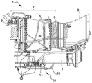
도 1은 본 발명에 따르는 배출 장치를 구비한 항공기 엔진의 개략적인 측면도이다.
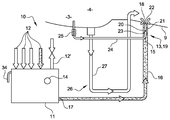
도 2는 본 발명에 따르는 배출 장치의 제 1 실시예의 개략적인 측면도이다.
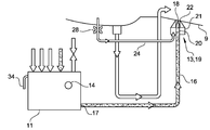
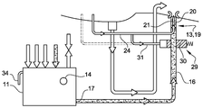
도 3 내지 도 10은 본 발명에 따르는 배출 장치의 대체 실시예의 개략적인 측면도이다. BRIEF DESCRIPTION OF THE DRAWINGS The present invention will become better understood when the following detailed description of the invention is given when it is given by way of illustration and not by way of limitation in the figures of the accompanying drawings, and the details, features and advantages of the present invention will become apparent.
1 is a schematic side view of an aircraft engine with a discharge device according to the invention;
Figure 2 is a schematic side view of a first embodiment of a discharge device according to the invention.
Figures 3 to 10 are schematic side views of an alternative embodiment of the discharge device according to the invention.
도 1을 참조하면, 항공기 엔진(1)(이 경우에는 헬리콥터의 엔진임)은 컴프레서(3), 연소실(4), 및 자유 터빈(6)에 연결되어 있는 터빈(5)에 의해 형성되어 있는 가스 발생장치(2)를 구비한다. 자유 터빈(6)은 기어박스(미도시)를 통해 파워 샤프트(7)를 이용하여 메인 로터(미도시)를 구동시킨다. 연소장치로부터의 가스는 배기 노즐(9) 속으로 토출된다. 1, an aircraft engine 1 (which in this case is the engine of a helicopter) is formed by a
엔진을 청소하기 위하여, 엔진(1)은 엔진으로부터 나오는 잔여 액체들(연료, 오일, 수분 응축물, 불순물 등)을 포집하도록 의도되어 있는 배출 장치(10)가 제공된다. In order to clean the engine, the
통상적으로, 배출 장치(10)는 포집장치(11), 및 엔진의 다양한 부품들로부터 유래하는 액체를 배출하기 위한 라인(12)들을 구비하고, 이 라인들의 유출구는 포집장치(11)에 이어져 있다. Typically, the
액체를 배출하기 위한 본 발명에 따르는 장치는 포집장치(11) 내에 보유되어 있는 액체를 펌핑하는 것과 상기 액체를 방출하는 것을 위한 수단, 및 액체가 비정상적인 방식으로 포집장치(11)에 의해 포집되었을 때를 표시하도록 설계되어 있는 모니터링 수단을 구비한다. An apparatus according to the present invention for discharging a liquid comprises means for pumping the liquid held in the collecting
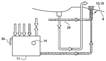
도 2에는 본 발명에 따르는 배출 장치(10)의 제 1 실시예가 나타나 있고, 펌핑 및 방출 수단과 모니터링 수단은 참조 번호 13과 14로 각각 지시되어 있다. Figure 2 shows a first embodiment of the
나타나 있는 예시에서, 펌핑 및 방출 수단(13)은 도관(16)을 이용하여 포집장치(11)의 액체 유출구(17)에 연결되는 유입구(15), 및 엔진(1)의 배기 노즐(9) 속으로 이어지는 유출구(18)를 구비한다. 포집장치(11)는 라인(12)들로부터 배출된 액체를 수용하고(화살표로 개략적으로 나타나 있음), 액체가 그 내부에 수용되는 포집장치의 내부 공동을 환기시키기 위한 환기구(12')가 제공된다. In the example shown, the pumping and discharging means 13 comprise an
이 경우, 펌핑 및 방출 수단(13)은 배출된 액체의 유동을 위한 제 1 라인(20)이 제공되어 있는 제트 펌프 이젝터(19)를 구비하고, 제 1 라인의 한쪽(상류) 단부에는 전술된 유입구(15)가 형성되어 있되 제 1 라인의 다른쪽(하류) 단부에는 전술된 유출구(18)가 형성되어 있다. 도 1에 개략적으로 나타나 있는 바와 같이, 상기 유출구(18)는 하류에 디퓨저를 형성하도록 유동 단면 내에 협착수단을 구비할 수 있다. In this case, the pumping and discharging means 13 has a jet pump ejector 19 provided with a
펌핑 및 방출 수단(13)은 또한 압축 가스를 분무하기 위한 제 2 라인(21)을 구비하고, 여기서 제 2 라인은 이 경우 제 1 라인(20) 안쪽으로 뻗어있고, 상기 제 2 라인(21)을 떠나는 분무된 가스가 라인(20)에서 유동하는 액체에 힘을 가하여 그 유출구(18)를 향하여 제트 노즐(9) 속으로 방출되도록 설계되어 있다. 이 압축 가스는 전술된 디퓨저 내에서 팽장하도록 의도되어 있고, 이는 부압을 만들어 내고, 배출된 액체에 힘을 가하여 제트 노즐(9) 속으로까지 유동하게 한다. The pumping and discharging means 13 also have a
따라서 제 2 라인(21)은 제 1 라인(20)의 유출구(18)의 영역 내에 위치되어 있는 압축 가스 유출구(22)를 구비한다. 제 2 라인의 유입구(23)는 도관(24)을 이용하여, 압축 가스를 엔진(1)으로부터 블리딩하기 위한 수단(도면에는 나타나 있지 않음)에 연결된다. 압축 가스는, 예컨대 평면 P25 또는 P3(평면 P25는 2개의 임펠러 사이에 위치되어 있고, 평면 P3는 이 임펠러들의 하류에 위치되어 있음)의 영역 내에서 엔진의 컴프레서(3)로부터 블리딩될 수 있다.The
펌핑의 활성화 및 액체가 제트 노즐(9) 속으로 방출되는 시간 모두를 제어하기 위하여, 도관(24)에는 개방되도록 의도되어 있는 플랩 밸브(25)가 제공되고, 블리딩된 압축 가스의 압력이 소정의 문턱값보다 크거나 같을 때 이 가스가 도관 속으로 이젝터(19)에 까지 지나가게 한다. 이 경우, 플랩 밸브(25)는 블리딩 수단의 가스 유출구를 둘러싸는 시트에 대하여 압축 스프링으로 바이어스되어 움직일 수 있는 볼을 이용하여 나타나 있다. 따라서, 플랩 밸브(25)는 압축 가스에 의하여 활성화된다. 특히 위 예시에서의 스프링의 스프링 상수에 좌우되는 전술된 가스 압력 문턱값은 배출된 액체가 방출되는 시간을 정확하게 제어하도록, 특히 엔진이 점화되자마자 상기 방출이 일어나지 않도록 결정되는 것이 바람직하다. In order to control both the activation of the pumping and the time the liquid is discharged into the
이 경우, 포집장치(11)를 모니터링하기 위한 수단(14)은 단일의 월류장치(34)로 나타나 있다. 본 발명에 따르면, 상기 모니터링 수단(14)은 포집장치(11)에 의해 수용되는 액체 유량이 펌핑 수단(13)(이젝터(19))의 전달량보다 많을 때 활성화되도록 설계되어 있다. 따라서, 모니터링 수단(14)은 액체가 비정상적인 방식으로 포집장치(11)에 의해 포집되었을 때를 표시하는 것, 특히 엔진의 정상적인 작동 동안의 보통의 양에 비해 너무 많은 배출된 액체의 양을 표시하는 것을 가능하게 한다. In this case, the
포집된 액체의 유량이 펌핑 수단(13)의 전달량 보다 많을 때, 모니터링 수단(14)은 시각적인 그리고/또는 전기적인 알람일 수 있는 신호를 내보내도록 설계될 수 있다. When the flow rate of the collected liquid is greater than the delivery amount of the pumping means 13, the monitoring means 14 may be designed to emit a signal which may be a visual and / or electrical alarm.
엔진의 정상적인 기능, 즉 일어날 수 있는 액체 손실 및 누출이 엔진의 기능에 영향을 미치지 않게 하는 기능에 대응하는 문턱값으로 펌핑 전달량을 세팅함으로써, 포집된 액체의 유량이 펌핑 전달량보다 많아지자마자 펌핑 수단(13)은 더 이상 포집된 액체를 방출할 필요가 없다. 포집장치에 의해 허용되는 경우, 포집장치(11) 내의 액체의 수준은 엔진 고장이 있는 경우라면 증가할 것이다. By setting the pumping transfer rate to a threshold value corresponding to the normal function of the engine, that is, the possible liquid loss and the function that does not affect the function of the engine, as soon as the flow rate of the captured liquid exceeds the pumping transfer rate, (13) no longer needs to discharge the collected liquid. If allowed by the collecting device, the level of liquid in the collecting
포집장치(11)에 오퍼레이터가 포집장치 내의 액체의 수준을 볼 수 있는 윈도우가 구비되어 있는 경우, 오퍼레이터에게 경고(시각적인 알람)하도록 의도되어 있는 이 윈도우는 모니터링 수단(14)에 구비되어 있다. This window, which is intended to warn the operator (visual alarm), is provided to the monitoring means 14 when the collecting
변형예 또는 추가적인 특징에서, 포집장치(11)는, 특히 포집된 액체의 양이 포집장치(11) 내의 액체의 저장량 보다 많은 경우 액체가 포집장치(11)로부터 빠져나가게 하도록 의도되어 있는 월류장치(34)를 구비할 수 있다. 알람 수단을 대신하거나 이에 추가하여, 오퍼레이터는 엔진 고장이 있는 경우라면 액체가 월류장치(34)의 수준을 지나갈 때 생기는 드립 마크를 볼 수 있으므로, 월류장치(34)에는 다른 타입의 시각적인 알람이 형성되어 있다. 월류장치(34)는 파이프를 이용하여 엔진 데크의 배수구 또는 보조적인 회수 용기에 연결될 수 있다. In a variant or additional feature, the collecting
전기적이고 시각적인 알람으로서, 모니터링 수단(14)은 센서를 구비할 수 있는데, 이 센서는 포집장치(11) 내의 액체의 수준을 탐지하도록 의도되어 있고, 예컨대 경고등을 이용하여 조종사가 볼 수 있되 항공기의 조종석을 위하여 의도되어 있는 신호를 내보내도록 의도되어 있다.As an electrical and visual alarm, the monitoring means 14 may comprise a sensor, which is intended to detect the level of the liquid in the collecting
따라서 모니터링 수단(14)은 오퍼레이터나 항공기 조종사에게 충분히 신속하게 경고하기 위해서 대량의 비정상적인 액체 누출을 탐지하는 것을 가능하게 한다. 알람의 활성화는 엔진 고장이 일어났다는 것, 및 유지 공정이 실행되어야만 한다는 것을 표시한다. Thus, the monitoring means 14 enables the operator or aircraft pilot to detect a large amount of abnormal liquid leakage in order to warn sufficiently quickly. Activation of the alarm indicates that an engine failure has occurred and that the maintenance process must be performed.
본 발명의 일부를 형성하지는 않지만, 도 2에 부분적으로 나타나 있는 엔진은 다른 배출 수단(26)을 구비하는데, 다른 배출 수단은 이 경우 연소실(4)에서 연소되지 않았던 연료를 포집하는데 사용되며 도관(27)을 이용하여 제트 노즐(9)을 향하여 상기 연료를 방출하는데 사용되고, 도관의 유출구는 제트 노즐 속으로 이어져 있다. 본 발명에 따르는 배출 장치(1)는 펌핑 수단이나 모니터링 수단이 제공되어 있지 않는 이러한 배출 수단(26)과 별개이다. Although not forming part of the present invention, the engine partially shown in Figure 2 has another exhaust means 26, which in this case is used to collect fuel which has not been burned in the
도 3 내지 도 10에는 본 발명의 대체 실시예가 나타나 있고, 여기에서 상술된 요소들은 동일한 참조 번호로 지시되어 있다. 3 to 10 show alternative embodiments of the present invention, wherein the elements described above are designated by the same reference numerals.
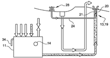
도 3의 변형예에서, 펌핑 수단(13)(이젝터(19))은 포집장치(11) 내에 통합되어 있다. 제 1 라인(20)은 포집장치(11)의 액체 유출구(17)에서 직접 들어맞고, 도관(16)의 한쪽 단부에 연결되며, 도관의 다른쪽 단부는 제트 노즐(9) 속으로 이어진다. 이젝터(19)의 제 2 라인(21)은 제 1 라인(20) 안쪽으로 뻗어있고, 그 유입구(23)는 플랩 밸브(25)가 제공될 수 있는 도관(24)을 이용하여, 엔진(1)으로부터 압축 가스를 블리딩하기 위한 수단에 연결된다. In the modification of Fig. 3, the pumping means 13 (ejector 19) are integrated in the collecting
도 3의 배출 장치는 마찬가지로 위 타입의 모니터링 수단(14)을 구비한다.The discharging device of Fig. 3 likewise comprises the monitoring means 14 of the above type.
이 장치는 도 2의 장치와 유사하게 기능한다.This apparatus functions similarly to the apparatus of Fig.
도 4의 실시예에서, 펌핑 수단(13)은 이젝터(19)를 구비하고, 이젝터의 제 1 라인(20)은 노즐을 형성하도록 제 2 라인(21) 안쪽에 들어맞는다. 제 1 라인(20)의 유입구는 도관(16)을 이용하여 포집장치(11)의 액체 유출구에 연결된다. 제 2 라인(21)의 유입구는 도관(24)을 이용하여 공기 블리딩 수단에 연결되고, 제 2 라인의 유출구는 제 1 라인(20)의 유출구 둘레에 뻗어있고 제트 노즐(9) 속으로 이어진다. In the embodiment of Figure 4 the pumping means 13 comprise an ejector 19 and the
이 경우, 이젝터(19)는 포집장치(11)로부터의 액체를 제트 노즐(9)을 향하여 분사하기 위하여 제 1 라인(20)의 유출구(18) 둘레에서 압축 가스를 빼냄으로써 작동되는 페인트 스프레이 건과 같은 방식으로 배기 노즐과 같이 기능한다. In this case, the ejector 19 is a paint spray gun (not shown), which is operated by extracting compressed gas around the
추가적으로, 이젝터의 제 2 라인(21)을 블리딩 수단에 연결하는 도관(24)에는 그 유동 단면 내에 협착수단(28)(도 2의 플랩 밸브(25)를 대신한 것임)이 제공된다. 이 협착수단(28)은 액체의 방출을 지연하는 것을 가능하게 해서, 액체의 방출은 엔진이 시동걸릴 때 일어나지 않는다. 따라서, 압력은 시동시 이젝터의 제 2 라인(21)에서 약간 증가하고, 액체는 소정의 압력 문턱치가 초과될 때 제트 노즐(9) 속으로 방출된다. In addition, the
배출 장치는 마찬가지로 위 타입의 모니터링 수단(14)을 구비한다. The discharge device is likewise equipped with monitoring means 14 of the above type.
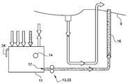
도 5의 대체 실시예는 주로, 도관(24)에는 플랩 밸브 또는 협착수단이 제공된다는 점에서 도 2의 실시예와 상이하다. 그 대신, 밸브(29), 예컨대 슬라이드 밸브는 포집장치(11)의 유출구(17)를 이젝터(19)의 제 1 라인(20)의 유입구에 연결하는 도관(16) 상에 들어맞는다.The alternative embodiment of Figure 5 differs from the embodiment of Figure 2 primarily in that the
밸브(29)는 도관(16)의 일부를 이용하여 포집장치(11)의 유출구(17)에 연결되는 유입구, 및 도관(16)의 다른 일부를 이용하여 이젝터(19)의 제 1 라인(20)의 유입구에 연결되는 유출구를 구비한다. 밸브(29)는 내부 부재(30)를 더 구비하는데, 이 내부 부재는 밸브(29)의 전술된 유출구 및/또는 유입구의 폐쇄된 포지션과 밸브(29)의 유입구와 유출구가 유체 연통하게 되어 있는 포지션 사이를 움직일 수 있다. 부재(30)는 스프링에 의해 밸브(29)의 폐쇄된 포지션으로 바이어스된다. 이 부재(30)의 움직임은, 이 경우 전술된 블리딩 수단에 의해 엔진으로부터 블리딩된 압축 가스의 일부에 해당하는 압축 가스에 의해 제어된다. 그렇게 하기 위하여, 블리딩 수단을 이젝터(19)에 연결하는 도관(24)은 부재가 그 내부에서 움직일 수 있게 들어맞는 밸브(29) 내의 공동에 연결되는 바이패스(31)를 구비한다. 밸브(29)는 블리딩된 가스의 압력이 소정의 문턱값 보다 크거나 같은 경우 개방되도록 의도되어 있는데, 이 문턱값은 위 예시에서의 스프링의 스프링 상수에 특히 좌우되고, 배출된 액체가 방출되는 시간을 정확하게 제어하도록, 특히 엔진이 점화되자마자 상기 방출이 일어나지 않도록 결정되는 것이 바람직하다. The
이를 대신하여, 도 5의 점선으로 나타나 있는 바와 같이, 도관(31)은 밸브 반대편 단부에 의해, 엔진의 컴프레서로부터 공기를 블리딩하기 위한 수단에 연결될 수 있다. Alternatively, the
도 6의 대체 실시예는 주로, 도관(24)이 엔진의 컴프레서로부터의 압축 공기가 아니라 엔진으로부터 가스를 제거하기 위한 시스템(미도시)으로부터의 압축 공기를 블리딩하기 위한 수단에 연결된다는 점에서 도 2의 실시예와 상이하다. 따라서, 액체는 엔진으로부터 가스를 제거하기 위한 시스템을 이용하여 제트 노즐(9) 속으로 방출된다. The alternative embodiment of FIG. 6 is primarily also in that the
도 7의 대체 실시예는 주로, 이젝터의 제 2 라인(21)을 블리딩 수단에 연결하는 도관(24)에는 그 유동 단면 내에 협착수단(28)(도 3의 플랩 밸브(25)를 대신한 것임)이 제공된다는 점에서 도 3의 실시예와 상이하다. 이 협착수단(28)은 도 4를 참조하여 기술된 협착수단과 같이 동일한 기능을 가진다. The alternative embodiment of FIG. 7 mainly comprises a
도 8의 대체 실시예는 주로, 이젝터의 제 2 라인(21)을 블리딩 수단에 연결하는 도관(24)에는 그 유동 단면 내에 협착수단(28)(도 2의 플랩 밸브(25)를 대신한 것임)이 제공된다는 점에서 도 2의 실시예와 상이하다. 이 협착수단(28)은 도 4를 참조하여 기술된 협착수단처럼 동일한 기능을 가진다. The alternative embodiment of FIG. 8 mainly comprises a
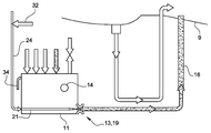
도 9의 대체 실시예는 주로, 이젝터(19)의 제 2 라인(21)을 블리딩 수단에 연결하는 도관(24)에는 전기적으로 제어되는 밸브(32)(도 3의 플랩 밸브(25)를 대신한 것임)가 제공된다는 점에서 도 3의 실시예와 상이하다. 이 밸브(32)는, 예컨대 상기 밸브가 엔진 컴퓨터에 의해 전송된 명령에 의해 활성화될 때 블리딩된 압축 가스를 통과하게 하기 위해서 개방되도록 의도되어 있다. An alternative embodiment of FIG. 9 mainly comprises an electrically controlled valve 32 (shown in FlG. 3 of FIG. 3) instead of the
도 10의 대체 실시예에서, 배출 장치의 펌핑 수단(13)은 도관(16) 상에 들어맞는 전기적인 또는 기계적인 펌프(33)를 구비하는데, 그 도관의 한쪽 단부는 포집장치(11)의 유출구(17)에 연결되고 그 반대편 단부는 제트 노즐(9) 속으로 이어진다. 펌프(33)는 활성화될 때 포집장치(11)로부터의 액체를 제트 노즐(9)로 나른다. 이 펌프의 전달량은 또한 전달 문턱치를 세팅하도록 보정되고, 전달 문턱치를 넘어서면 모니터링 장치는 엔진의 비정상적인 기능을 표시한다. 이 변형예는 밸브, 협착수단 또는 블리딩되는 공기를 필요로 하지 않는다. 배출 장치는 마찬가지로 위 타입의 모니터링 수단(14)을 구비한다. 10, the pumping means 13 of the discharge device has an electric or mechanical pump 33 which is fitted on the
Claims (10)
상기 장치는 포집장치 내에 보유되어 있는 액체를 펌핑하는 것과 상기 액체를 방출하는 것을 위한 수단(13), 및 액체가 비정상적인 방식으로 포집장치(11)에 의해 포집되었을 때를 표시하도록 설계되어 있는 모니터링 수단(14)을 구비하고,
상기 모니터링 수단(14)은 포집된 액체의 유량이 펌핑 수단(13)의 전달량 보다 많을 때 활성화되도록 설계되어 있는 것을 특징으로 하는 장치(10).An apparatus (10) for discharging liquid for an aircraft engine (1) having a collecting device (11) designed to collect liquid discharged from an aircraft engine,
The device comprises means (13) for pumping the liquid held in the collecting device and for discharging the liquid, and monitoring means designed to indicate when the liquid has been collected by the collecting device (11) in an abnormal manner (14)
Characterized in that the monitoring means (14) is designed to be activated when the flow rate of the collected liquid is greater than the delivery amount of the pumping means (13).
펌핑 수단(13)은 전기식, 기계식 또는 유압식 펌프(33)를 구비하거나 제트 펌프 이젝터(19)를 구비하고,
이 이젝터는, 그 한쪽 단부에는 포집장치(11) 내에 보유되어 있는 액체를 위한 유입구(15)가 형성되어 있되 그 다른쪽 단부에는 액체를 방출하기 위한 유출구(18)가 형성되어 있는, 배출된 액체의 유동을 위한 제 1 라인(20), 및 압축 가스를 분무하기 위한 제 2 라인(21)을 구비하고,
여기서 제 2 라인은 제 1 라인(20) 둘레나 안쪽에 뻗어있고, 상기 제 2 라인(21)을 떠나는 분무된 가스가 액체에 힘을 가하여 제 1 라인(20)의 유출구를 통해 방출되도록 설계되어 있는 것을 특징으로 하는 장치(10).The method according to claim 1,
The pumping means 13 comprises an electric, mechanical or hydraulic pump 33 or has a jet pump ejector 19,
The ejector has an inlet 15 for liquid held in the collecting device 11 at one end thereof and an outlet 18 for discharging liquid at the other end thereof. And a second line (21) for spraying the compressed gas, wherein the first line (20)
Wherein the second line extends around the first line 20 and is designed such that the atomised gas leaving the second line 21 exerts a force on the liquid through the outlet of the first line 20 (10). ≪ / RTI >
제 1 라인(20)은 밸브(29)에 연결되는 것을 특징으로 하는 장치(10).3. The method of claim 2,
Characterized in that the first line (20) is connected to a valve (29).
제 2 라인(21)은 가능한 한 밸브(25) 또는 유동 단면의 협착수단(28)을 이용하여 압축 가스를 블리딩하기 위한 수단에 연결되는 가스 유입구(23)를 구비하는 것을 특징으로 하는 장치(10).The method according to claim 2 or 3,
Characterized in that the second line (21) comprises a gas inlet (23) connected to the valve (25) or means for bleeding the compressed gas by means of the stiffening means (28) ).
펌핑 수단(13)은 포집장치(11)에 통합되어 있고, 또는 포집장치로부터 떨어져 위치되어 있으면서 도관(16)을 이용하여 그 액체 유출구(17)에 연결되는 것을 특징으로 하는 장치(10).5. The method according to any one of claims 1 to 4,
Characterized in that the pumping means (13) are integrated in the collecting device (11) or are located away from the collecting device and are connected to the liquid outlet (17) by means of a conduit (16).
모니터링 수단(14)은 포집장치(11)를 검사하는 오퍼레이터가 볼 수 있도록 설계되어 있는 또는 항공기의 조종석을 위하여 의도되어 있는 신호를 내보내도록 설계되어 있는 시각적인 그리고/또는 전기적인 알람을 구비하는 것을 특징으로 하는 장치(10).6. The method according to any one of claims 1 to 5,
The monitoring means 14 may comprise visual and / or electrical alarms designed to be visible to an operator inspecting the collecting device 11, or designed to emit signals intended for the cockpit of an aircraft (10).
포집장치(11)는 포집된 액체의 유량이 펌핑 수단(13)의 전달량 보다 많을 때 액체가 포집장치(11)로부터 빠져나가게 하도록 설계되어 있는 월류장치(34)를 구비하는 것을 특징으로 하는 장치(10).7. The method according to any one of claims 1 to 6,
Characterized in that the collecting device (11) comprises a overflow device (34) designed to allow the liquid to escape from the collecting device (11) when the flow rate of the collected liquid is greater than the transfer amount of the pumping means 10).
상기 엔진은 제 1 항 내지 제 7 항 중 어느 한 항에 따르는 적어도 하나의 장치(10)를 구비하고, 펌핑 수단(13)의 유출구는 도관(16)을 이용하여 제트 노즐(9)에 이어지거나 직접 제트 노즐(9)에 이어지는 것을 특징으로 하는 엔진(1).An aircraft engine (1) having an exhaust nozzle (9) for combustion gas,
Characterized in that the engine comprises at least one device (10) according to one of the claims 1 to 7 and the outlet of the pumping means (13) is connected to the jet nozzle (9) by means of a conduit Directly follows the jet nozzle (9).
펌핑 수단(13)은 엔진으로부터 가스를 제거하기 위한 컴프레서나 시스템으로부터 가스를 블리딩하기 위한 수단에 연결되는 것을 특징으로 하는 엔진(1).An engine (1) according to claim 8 as a subordinate item of claim 4,
Characterized in that the pumping means (13) are connected to means for bleeding gas from a compressor or system for removing gas from the engine.
상기 방법은 장치(10)를 모니터링하기 위한 수단(14)이 활성화된 후에 엔진을 유지하는 단계를 구비하는 것을 특징으로 하는 방법.A method for inspecting an engine according to claim 8 or 9,
Characterized in that the method comprises the step of maintaining the engine after the means (14) for monitoring the device (10) is activated.
Applications Claiming Priority (3)
| Application Number | Priority Date | Filing Date | Title |
|---|---|---|---|
| FR1363087 | 2013-12-19 | ||
| FR1363087A FR3015567B1 (en) | 2013-12-19 | 2013-12-19 | DEVICE FOR DRAINING FLUIDS FOR AN AIRCRAFT ENGINE |
| PCT/FR2014/053333 WO2015092243A1 (en) | 2013-12-19 | 2014-12-15 | Fluid-draining device for an aircraft engine |
Publications (1)
| Publication Number | Publication Date |
|---|---|
| KR20160094990A true KR20160094990A (en) | 2016-08-10 |
Family
ID=50289992
Family Applications (1)
| Application Number | Title | Priority Date | Filing Date |
|---|---|---|---|
| KR1020167016369A KR20160094990A (en) | 2013-12-19 | 2014-12-15 | Fluid-draining device for an aircraft engine |
Country Status (10)
| Country | Link |
|---|---|
| US (1) | US10539077B2 (en) |
| EP (1) | EP3084187B1 (en) |
| JP (1) | JP2017503951A (en) |
| KR (1) | KR20160094990A (en) |
| CN (1) | CN105829681B (en) |
| CA (1) | CA2933531C (en) |
| FR (1) | FR3015567B1 (en) |
| PL (1) | PL3084187T3 (en) |
| RU (1) | RU2666719C1 (en) |
| WO (1) | WO2015092243A1 (en) |
Families Citing this family (11)
| Publication number | Priority date | Publication date | Assignee | Title |
|---|---|---|---|---|
| US11512811B2 (en) | 2016-07-12 | 2022-11-29 | Sikorsky Aircraft Corporation | System and method for detecting a lubricant-out condition in an aircraft gearbox |
| NO343014B1 (en) * | 2017-03-24 | 2018-10-01 | Karmoey Winch As | A pumping system and method |
| FR3082560B1 (en) | 2018-06-14 | 2020-08-28 | Safran Aircraft Engines | ON-BOARD SYSTEM AND METHOD FOR DRAINING AN AIRCRAFT ENGINE |
| FR3082507B1 (en) * | 2018-06-14 | 2022-01-28 | Safran Aircraft Engines | DEVICE AND METHOD FOR DRAINING AND MONITORING DRAINED FLUID FROM AN AIRCRAFT ENGINE |
| FR3082508B1 (en) | 2018-06-14 | 2021-12-03 | Safran Aircraft Engines | ON-BOARD DRAINAGE TANK OF AN AIRCRAFT ENGINE |
| CN109319159B (en) * | 2018-11-28 | 2024-03-15 | 江西荣力航空工业有限公司 | Residual oil collecting and discharging device of helicopter engine |
| CN111980803B (en) * | 2019-05-24 | 2022-03-15 | 中国航发商用航空发动机有限责任公司 | Aircraft engine |
| EP3798113B1 (en) * | 2019-09-30 | 2023-03-29 | Rohr, Inc. | Fluid drainage system for an aircraft propulsion system |
| FR3114128B1 (en) * | 2020-09-14 | 2022-11-04 | Airbus Helicopters | Drainage system of an aircraft combustion engine and associated aircraft |
| FR3137408B1 (en) | 2022-06-29 | 2024-06-07 | Safran Helicopter Engines | Drained assembly of an aircraft turbomachine |
| FR3143008A1 (en) | 2022-12-09 | 2024-06-14 | Airbus Helicopters | Aircraft equipped with an engine and an exhaust duct around an engine ejection nozzle |
Family Cites Families (18)
| Publication number | Priority date | Publication date | Assignee | Title |
|---|---|---|---|---|
| FR1597209A (en) * | 1968-02-02 | 1970-06-22 | ||
| US3623053A (en) * | 1969-10-23 | 1971-11-23 | Gen Electric | Leak-detecting apparatus |
| GB1402996A (en) * | 1971-10-28 | 1975-08-13 | Plessey Co Ltd | Fuel-supply systems for gas-turbine engines |
| JPS61123787A (en) * | 1984-11-16 | 1986-06-11 | Mitsubishi Heavy Ind Ltd | Abnormality monitoring device for hydraulic equipment |
| US5285636A (en) * | 1992-10-28 | 1994-02-15 | General Electric Company | Diagnostic drain mast for a gas turbine engine |
| JP3307734B2 (en) * | 1993-09-29 | 2002-07-24 | 株式会社日立国際電気 | Flight data recorder with alarm function |
| FR2726603B1 (en) * | 1994-11-09 | 1996-12-13 | Snecma | DEVICE FOR ACTIVE CONTROL OF THE COMBUSTION AND DECOKEFACTION INSTABILITIES OF A FUEL INJECTOR |
| IT1318110B1 (en) * | 2000-07-03 | 2003-07-23 | Nuovo Pignone Spa | DISCHARGE AND REFRIGERATION SYSTEM FOR THE CUSHIONS OF AN AGAS TURBINE |
| US6578361B1 (en) * | 2001-08-30 | 2003-06-17 | General Electric Co. | Methods and apparatus for determining engine cavity leakage |
| US6571562B2 (en) * | 2001-10-08 | 2003-06-03 | Honeywell International Inc. | Witness drain valve |
| JP4504231B2 (en) | 2005-03-02 | 2010-07-14 | 株式会社東芝 | Power plant reheat system |
| FR2913250B1 (en) * | 2007-03-02 | 2009-05-29 | Turbomeca Sa | METHOD FOR STARTING A GAS TURBINE HELICOPTER ENGINE, FUEL SUPPLY CIRCUIT FOR SUCH AN ENGINE, AND MOTOR HAVING SUCH A CIRCUIT |
| EP2052792A3 (en) * | 2007-10-09 | 2011-06-22 | Gas Turbine Efficiency Sweden AB | Drain valve, washing system and sensing of rinse and wash completion |
| EP2536536A1 (en) * | 2010-02-17 | 2012-12-26 | GARDENA Manufacturing GmbH | Power tools |
| EP2681111B1 (en) * | 2011-03-01 | 2016-07-06 | Short Brothers Plc | A draining device |
| US8708554B2 (en) * | 2011-05-12 | 2014-04-29 | Arrowhead Products Corporation | Leak detection apparatus for aircraft bleed air systems |
| FR2986583B1 (en) * | 2012-02-08 | 2014-02-28 | Eurocopter France | CIRCUIT FOR DRAINING A LIQUID FROM A MOTORIZATION UNIT EQUIPPED WITH A GIRAVION, INCORPORATING AN APPARATUS FOR MONITORING AN EXCESSIVE FLOW OF THE FLUID |
| WO2014210413A1 (en) * | 2013-06-27 | 2014-12-31 | Mag Aerospace Industries, Llc | Water management system |
-
2013
- 2013-12-19 FR FR1363087A patent/FR3015567B1/en active Active
-
2014
- 2014-12-15 US US15/104,462 patent/US10539077B2/en active Active
- 2014-12-15 WO PCT/FR2014/053333 patent/WO2015092243A1/en active Application Filing
- 2014-12-15 RU RU2016125764A patent/RU2666719C1/en active
- 2014-12-15 EP EP14827837.7A patent/EP3084187B1/en active Active
- 2014-12-15 JP JP2016539936A patent/JP2017503951A/en active Pending
- 2014-12-15 KR KR1020167016369A patent/KR20160094990A/en not_active Application Discontinuation
- 2014-12-15 PL PL14827837T patent/PL3084187T3/en unknown
- 2014-12-15 CA CA2933531A patent/CA2933531C/en active Active
- 2014-12-15 CN CN201480068556.2A patent/CN105829681B/en active Active
Also Published As
| Publication number | Publication date |
|---|---|
| RU2016125764A (en) | 2018-01-24 |
| EP3084187B1 (en) | 2020-02-26 |
| FR3015567B1 (en) | 2015-12-25 |
| RU2666719C1 (en) | 2018-09-11 |
| CA2933531A1 (en) | 2015-06-25 |
| CN105829681A (en) | 2016-08-03 |
| JP2017503951A (en) | 2017-02-02 |
| EP3084187A1 (en) | 2016-10-26 |
| US20160312707A1 (en) | 2016-10-27 |
| CN105829681B (en) | 2018-07-10 |
| WO2015092243A1 (en) | 2015-06-25 |
| PL3084187T3 (en) | 2020-06-29 |
| US10539077B2 (en) | 2020-01-21 |
| FR3015567A1 (en) | 2015-06-26 |
| CA2933531C (en) | 2022-03-22 |
Similar Documents
| Publication | Publication Date | Title |
|---|---|---|
| KR20160094990A (en) | Fluid-draining device for an aircraft engine | |
| EP2594487B1 (en) | Fuel tank flammability reduction and inerting system and methods thereof | |
| US8171932B2 (en) | Oxygen breathing device for an aircraft | |
| CN103389191B (en) | By the device of the transmission case sealing of suction monitoring rotocraft | |
| JP2017503951A5 (en) | ||
| US8578763B2 (en) | System and method for fuel system health monitoring | |
| US20110282501A1 (en) | Method of detecting a liquid fuel leak in a gas turbine | |
| JP3439823B2 (en) | Gas turbine engine operation method | |
| CN103249930B (en) | The monitoring of airplane engine fuel oil supply system filter | |
| US12013082B2 (en) | Method for monitoring a fluid system lubricating a mechanical system | |
| US9951699B2 (en) | Method of detecting a malfunction of a valve in a turboshaft engine | |
| CN109931190B (en) | Jam detection device and jam detection method | |
| JP7340442B2 (en) | Aircraft maintenance systems and methods | |
| US20210052999A1 (en) | Method and system for monitoring a fluid system configured to operate with a filter | |
| US10513988B2 (en) | Fuel circuit comprising means for controlling a pump | |
| CN105089866A (en) | Method for diagnosing fuel tank vent valve | |
| JP6506063B2 (en) | Fuel control system for vehicles | |
| CN112903299A (en) | Aeroengine test bed and fire extinguishing method | |
| US10054002B2 (en) | Method for assisting with the detection of damage to a turbojet duct | |
| EP2143636A1 (en) | Oxygen breathing device for an aircraft | |
| van't Hoff et al. | Icing Qualification Wind Tunnel Test of Helicopter Engine with Inlet Barrier Filter Air Intake | |
| CN117890035A (en) | Fault monitoring device for exhaust valve | |
| KR20160023122A (en) | Apparatus and method for controlling a common rail system |
Legal Events
| Date | Code | Title | Description |
|---|---|---|---|
| E902 | Notification of reason for refusal | ||
| E601 | Decision to refuse application |