KR20160094792A - Switchgear having shutter and push type door - Google Patents
Switchgear having shutter and push type door Download PDFInfo
- Publication number
- KR20160094792A KR20160094792A KR1020150016270A KR20150016270A KR20160094792A KR 20160094792 A KR20160094792 A KR 20160094792A KR 1020150016270 A KR1020150016270 A KR 1020150016270A KR 20150016270 A KR20150016270 A KR 20150016270A KR 20160094792 A KR20160094792 A KR 20160094792A
- Authority
- KR
- South Korea
- Prior art keywords
- door
- shutter
- control room
- room body
- chamber
- Prior art date
- Legal status (The legal status is an assumption and is not a legal conclusion. Google has not performed a legal analysis and makes no representation as to the accuracy of the status listed.)
- Granted
Links
Images


Classifications
-
- H—ELECTRICITY
- H02—GENERATION; CONVERSION OR DISTRIBUTION OF ELECTRIC POWER
- H02B—BOARDS, SUBSTATIONS OR SWITCHING ARRANGEMENTS FOR THE SUPPLY OR DISTRIBUTION OF ELECTRIC POWER
- H02B1/00—Frameworks, boards, panels, desks, casings; Details of substations or switching arrangements
- H02B1/26—Casings; Parts thereof or accessories therefor
- H02B1/30—Cabinet-type casings; Parts thereof or accessories therefor
- H02B1/38—Hinged covers or doors
Landscapes
- Engineering & Computer Science (AREA)
- Power Engineering (AREA)
- Patch Boards (AREA)
Abstract
본 발명의 도어를 열어도 도어가 전면으로 돌출되지 배전반에 관한 것으로서, 본 발명에 의한 배전반은 전면이 개방된 박스 형태로 형성된 제어실 몸체; 상기 제어실 몸체의 전면의 중앙 부분에 설치되며, 상기 제어실 몸체의 좌측면과 우측면에 대해 회전 가능하게 설치되어 상기 제어실 몸체 전면의 중앙 부분을 개폐하는 수평 회전 도어; 상기 제어실 몸체의 전면의 상측에 상기 제어실 몸체의 상면에서 상기 수평 회전 도어의 상단까지 상하 방향으로 슬라이드 가능하게 설치되어 상기 제어실 몸체 전면의 상부를 개폐하는 상부 셔터 도어; 및 상기 제어실 몸체의 전면의 하측에 상기 제어실 몸체의 하면에서 상기 수평 회전 도어의 하단까지 상하 방향으로 슬라이드 가능하게 설치되어 상기 제어실 몸체 전면의 하부를 개폐하는 하부 셔터 도어;를 포함한다. 또한, 상기 제어실 몸체의 상면에는 상기 상부 셔터 도어가 수용되는 상부 셔터 수용부가 형성되며, 상기 제어실 몸체의 하면에는 상기 하부 셔터 도어가 수용되는 하부 셔터 수용부가 형성되고, 상기 제어실 몸체의 전면의 양측에는 상기 상부 셔터 도어와 하부 셔터 도어의 상하 이동을 안내하는 셔터 가이드부가 마련된다.The present invention relates to a switchgear having a door protruding from a front surface thereof even when the door is opened. The switchgear according to the present invention comprises: A horizontal rotation door installed at a central portion of a front surface of the control room body and rotatably installed on a left side surface and a right side surface of the control room body to open and close a central portion of the front surface of the control room body; An upper shutter door slidably installed on an upper surface of the control room body from an upper surface of the control room body to an upper end of the horizontal rotation door to open and close an upper portion of a front surface of the control room body; And a lower shutter door slidably installed in a lower portion of the front surface of the control room body in a vertical direction from a lower surface of the control room body to a lower end of the horizontal rotation door to open and close a lower portion of a front surface of the control room body. In addition, a top shutter receiving portion for receiving the upper shutter door is formed on the upper surface of the control room body, a lower shutter receiving portion for receiving the lower shutter door is formed on a lower surface of the control room body, A shutter guide portion for guiding upward and downward movement of the upper shutter door and the lower shutter door is provided.
Description
본 발명은 셔터 및 푸시 타입 도어를 구비한 배전반에 관한 것으로서, 더욱 상세하게는 배전반의 유지보수 공간을 축소할 수 있도록 전면 도어가 외부로 돌출되지 않도록 셔터 및 푸시 타입 도어로 구조를 개선한 셔터 및 푸시 타입 도어를 구비한 배전반에 관한 것이다.BACKGROUND OF THE
일반적으로, 배전반 또는 배전함은 외부에서 인입되는 전기를 분기시켜주는 개폐기를 비롯한 배전기구, 디지털 전력보호 감시제어장치 등이 설치되는 것으로서, 대략 직육면체의 박스 형상으로 형성된다.Generally, an electric distribution board or an electric distribution box is provided with a power distributing mechanism including a switch for branching electricity drawn from the outside, a digital power protection monitoring control device, and the like, and is formed into a box shape of a substantially rectangular parallelepiped.
그런데, 이와 같은 종래 기술에 의한 배전반은 전면에 여닫이문 형태로 설치된 전면 도어가 설치되어 있어 전면을 개폐할 수 있다. However, the front panel of the conventional switchboard is provided with a front door provided in the form of a hinged door, so that the front panel can be opened and closed.
이와 같은 종래 기술에 의한 배전반은 내부를 점검하기 위해서는 전면 도어를 열어야 하므로, 배전반의 전면과 측면에 전면 도어를 개방하기 위한 공간이 반드시 필요하다. In order to inspect the inside of the switchboard according to the related art, the front door must be opened. Therefore, a space is required to open the front door on the front and side surfaces of the switchboard.
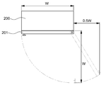
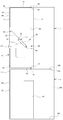
구체적으로, 도 1에 도시된 바와 같이 배전반(200)의 전면으로는 배전반(200)의 전면 도어(201)를 열 수 있도록 배전반(200)의 폭(W)에 대응하는 공간이 요구되고, 배전반(200)의 일측면으로는 배전반(200)의 폭(W)의 1/2 정도의 공간이 요구된다. 따라서, 종래 기술에 의한 배전반(200)은 공간 활용 측면에서 불리하다는 문제점이 있다.1, a space corresponding to the width W of the
또한, 종래 기술에 의한 배전반은 전면 도어가 개방된 상태에서는 전면 도어가 돌출되어 있으며, 개방된 전면 도어를 움직이지 않도록 하기 위한 도어 스토퍼가 필요하다는 문제점이 있다. In addition, in the conventional switchboard, the front door is protruded when the front door is opened, and a door stopper is required to prevent the front door from moving.
또한, 종래 기술에 의한 배전반은 전면 도어가 세로 측면에 설치된 힌지에 의해 지지되므로, 회전 길이와 각도가 크기 때문에 전면 도어의 충격에 의한 진동으로 배전반의 오작동 우려가 있다는 문제점이 있다. In addition, since the front door is supported by the hinge provided on the longitudinal side of the cabinet of the related art, there is a problem that the cabinet may malfunction due to the vibration due to the impact of the front door.
또한, 종래 기술에 의한 배전반은 전면 도어에 불평형 하중이 작용하는 구조이므로, 전면 도어의 처짐 현상이 발생될 수 있다는 문제점이 있다.In addition, since the conventional distribution board has a structure in which an unbalanced load acts on the front door, there is a problem that a deflection phenomenon of the front door may occur.
<관련 선행기술 문헌>≪ Related Prior Art Literature >
1. 대한민국 등록특허 제10-0639209호1. Korean Patent No. 10-0639209
본 발명은 상기와 같은 종래 기술의 문제점을 해결하기 위하여 창안한 것으로서, 개방시 전면으로 돌출되지 않고 배전반의 전면을 개방할 수 있는 셔터 및 푸시 타입 도어를 구비한 배전반을 제공하는 것을 과제로 한다.
Disclosure of Invention Technical Problem [8] Accordingly, the present invention has been made keeping in mind the above problems occurring in the prior art, and an object of the present invention is to provide an electrical switchboard having a shutter and a push-type door,
상기 과제를 달성하기 위하여 본 발명의 일 측면에 따르면,According to an aspect of the present invention,
전면이 개방된 박스 형태로 형성된 제어실 몸체;A control chamber body formed in a box shape having a front surface opened;
상기 제어실 몸체의 전면의 중앙 부분에 설치되며, 상기 제어실 몸체의 좌측면과 우측면에 대해 회전 가능하게 설치되어 상기 제어실 몸체 전면의 중앙 부분을 개폐하는 수평 회전 도어;A horizontal rotation door installed at a central portion of a front surface of the control room body and rotatably installed on a left side surface and a right side surface of the control room body to open and close a central portion of the front surface of the control room body;
상기 제어실 몸체의 전면의 상측에 상기 제어실 몸체의 상면에서 상기 수평 회전 도어의 상단까지 상하 방향으로 슬라이드 가능하게 설치되어 상기 제어실 몸체 전면의 상부를 개폐하는 상부 셔터 도어; 및An upper shutter door slidably installed on an upper surface of the control room body from an upper surface of the control room body to an upper end of the horizontal rotation door to open and close an upper portion of a front surface of the control room body; And
상기 제어실 몸체의 전면의 하측에 상기 제어실 몸체의 하면에서 상기 수평 회전 도어의 하단까지 상하 방향으로 슬라이드 가능하게 설치되어 상기 제어실 몸체 전면의 하부를 개폐하는 하부 셔터 도어;를 포함하며,And a lower shutter door slidably installed on a lower side of a front surface of the control room body from a lower surface of the control room body to a lower end of the horizontal rotation door to open and close a lower portion of the front surface of the control room body,
상기 제어실 몸체의 상면에는 상기 상부 셔터 도어가 수용되는 상부 셔터 수용부가 형성되며, 상기 제어실 몸체의 하면에는 상기 하부 셔터 도어가 수용되는 하부 셔터 수용부가 형성되고, 상기 제어실 몸체의 전면의 양측에는 상기 상부 셔터 도어와 하부 셔터 도어의 상하 이동을 안내하는 셔터 가이드부가 마련된 것을 특징으로 하는 셔터 및 푸시 타입 도어를 구비한 배전반이 제공된다.A lower shutter receiving portion in which the lower shutter door is received is formed on a lower surface of the control room body, and a lower shutter receiving portion is formed on the upper surface of the control room body, There is provided an electrical switchboard comprising a shutter and a push type door, characterized in that a shutter guide portion for guiding vertical movement of the shutter door and the lower shutter door is provided.
이때, 상기 수평 회전 도어의 양측단이 상기 제어실 몸체의 좌측면과 우측면에 힌지 결합되고, 상기 수평 회전 도어의 양측단과 상기 제어실 몸체의 좌측면과 우측면 각각의 사이에는 2절 링크가 설치될 수 있다. At this time, both side ends of the horizontal rotation door are hinged to the left and right sides of the control room body, and a two-link link may be installed between both side ends of the horizontal rotation door and each of the left side and the right side of the control room body. .
또한, 상기 수평 회전 도어는 상기 제어실 몸체의 내측으로 90도 회전할 수 있다. In addition, the horizontal rotation door may be rotated 90 degrees to the inside of the control room body.
또한, 상기 수평 회전 도어의 양측단에는 한 쌍의 힌지 브라켓이 설치되며, 상기 한 쌍의 힌지 브라켓은 수평 회전 도어 높이의 중간을 통과하고, 상기 배전반의 하면에 평행하며, 상기 수평 회전 도어의 무게 중심보다 상기 수평 회전 도어에서 먼 곳을 통과하는 직선상에 설치되는 힌지를 중심으로 회전할 수 있도록 설치될 수 있다. A pair of hinge brackets are provided at both ends of the horizontal rotating door, the pair of hinge brackets passing through the middle of the height of the horizontal rotating door, parallel to the lower surface of the switchboard, And a hinge provided on a straight line passing through a place farther from the horizontal rotation door than the center.
또한, 상기 배전반 후면의 내측면에는 상기 수평 회전 도어의 회전을 180도로 제한하는 스토퍼가 설치될 수 있다. A stopper may be provided on an inner surface of the rear surface of the switchboard to limit rotation of the horizontal rotating door by 180 degrees.
또한, 상기 차단기실은, 전면이 개방된 박스 형태로 형성된 차단기실 몸체; 상기 차단기실 몸체의 전면에 상하 방향으로 슬라이드 가능하게 설치되어 상기 차단기실 몸체 전면을 개폐하는 차단기실 셔터 도어;를 포함하며, 상기 차단기실 몸체의 상면에는 상기 차단기실 셔터 도어가 수용되는 차단기실 셔터 수용부가 형성되며, 상기 차단기실 몸체의 전면의 양측에는 상기 차단기실 셔터 도어의 상하 이동을 안내하는 차단기실 셔터 가이드부가 마련될 수 있다.
In addition, the breaker room may include a shielding box body formed in a box shape with a front surface opened; And a cutter chamber shutter door slidably installed on a front surface of the cutter chamber body to open and close the cutter chamber body front surface, And a blocking chamber chamber shutter guide for guiding upward and downward movement of the blocking chamber chamber shutter door may be provided on both sides of the front surface of the blocking chamber chamber body.
상기와 같은 구조를 갖는 본 발명의 일 실시예에 의한 셔터 및 푸시 타입 도어를 구비한 배전반은, 제어실 몸체의 전면이 슬라이드 이동하는 상부 셔터 도어 및 하부 셔터 도어와 수평축을 중심으로 제어실 몸체의 내측으로 회전하는 수평 회전 도어에 의해 개폐되므로, 전면으로 돌출되는 도어가 없다. 따라서, 종래 기술에 의한 배전반보다 유지보수를 위한 공간을 줄일 수 있다는 이점이 있다. The switchboard having the shutter and the push type door according to an embodiment of the present invention having the above structure includes an upper shutter door and a lower shutter door through which the front surface of the control room body slides, Since the door is opened and closed by the rotating horizontal rotary door, there is no door projecting to the front. Therefore, there is an advantage that the space for maintenance can be reduced compared to the conventional switchboard.
또한, 본 발명의 일 실시예에 의한 셔터 및 푸시 타입 도어를 구비한 배전반은 종래 기술에 의한 배전반과 달리 세로축을 중심으로 회전하는 여닫이문을 구비하지 않으므로, 진동이나 충격에 강하다는 이점이 있다.
In addition, the switchboard having the shutter and the push-type door according to the embodiment of the present invention is advantageous in that it is resistant to vibration and shock because it does not have a hinged door that rotates about the vertical axis unlike the conventional switchboard.
도 1은 종래 기술에 의한 배전반의 전면 도어를 개방할 때, 필요한 공간을 설명하기 위한 도면;
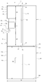
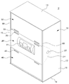
도 2는 본 발명의 일 실시예에 의한 셔터 및 푸시 타입 도어를 구비한 배전반의 전면 도어가 닫힌 상태를 나타내는 사시도;
도 3은 도 2의 셔터 및 푸시 타입 도어를 구비한 배전반을 나타내는 단면도;
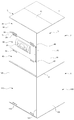
도 4는 도 2의 셔터 및 푸시 타입 도어를 구비한 배전반의 상부 셔터 도어,하부 셔터 도어, 및 차단실 셔터 도어를 개방한 상태를 나타내는 사시도;
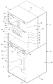
도 5는 도 2의 셔터 및 푸시 타입 도어를 구비한 배전반의 상부 셔터 도어, 하부 셔터 도어, 수평 회전 도어, 및 차단실 셔터 도어가 개방된 상태를 나타내는 사시도;
도 6은 도 5의 셔터 및 푸시 타입 도어를 구비한 배전반을 나타내는 단면도;
도 7은 본 발명의 일 실시예에 의한 셔터 및 푸시 타입 도어를 구비한 배전반의 제어실의 다른 예에서 전면 도어가 닫힌 상태를 나타내는 사시도;
도 8은 도 7의 제어실을 나타내는 단면도;
도 9는 도 7의 제어실의 상부 셔터 도어, 하부 셔터 도어, 및 수평 회전 도어가 개방된 상태를 나타내는 사시도;
도 10은 도 9의 제어실을 나타내는 단면도이다.1 is a view for explaining a space required when a front door of a switchboard according to the related art is opened;
2 is a perspective view showing a state where a front door of a switchboard having a shutter and a push type door is closed according to an embodiment of the present invention;
Fig. 3 is a cross-sectional view of the switchboard of Fig. 2 with a push-type door; Fig.
FIG. 4 is a perspective view showing a state in which the upper shutter door, the lower shutter door, and the shutoff chamber shutter door of the switchboard having the shutter and the push type door of FIG. 2 are opened;
Fig. 5 is a perspective view showing a state in which the upper shutter door, the lower shutter door, the horizontal rotation door, and the shutoff chamber shutter door of the distribution board having the shutter and the push type door of Fig. 2 are opened;
Fig. 6 is a cross-sectional view showing the switchboard of Fig. 5 with a shutter and a push-type door; Fig.
7 is a perspective view showing a state in which the front door is closed in another example of the control room of the switchboard having the shutter and the push type door according to the embodiment of the present invention;
8 is a cross-sectional view of the control chamber of Fig. 7;
FIG. 9 is a perspective view showing a state in which the upper shutter door, the lower shutter door, and the horizontal rotation door of the control room of FIG. 7 are opened;
10 is a sectional view showing the control chamber of Fig.
이하, 첨부된 도면을 참조하여 본 발명에 의한 셔터 및 푸시 타입 도어를 구비한 배전반의 실시 예들에 대하여 상세하게 설명한다. DESCRIPTION OF THE PREFERRED EMBODIMENTS Hereinafter, embodiments of a switchboard having a shutter and a push type door according to the present invention will be described in detail with reference to the accompanying drawings.
이하에서 설명되는 실시 예는 본 발명의 이해를 돕기 위하여 예시적으로 나타낸 것이며, 본 발명은 여기서 설명되는 실시 예들과 다르게 다양하게 변형되어 실시될 수 있음이 이해되어야 할 것이다. 다만, 이하에서 본 발명을 설명함에 있어서, 관련된 공지 기능 혹은 구성요소에 대한 구체적인 설명이 본 발명의 요지를 불필요하게 흐릴 수 있다고 판단되는 경우 그 상세한 설명 및 구체적인 도시를 생략한다. 또한, 첨부된 도면은 발명의 이해를 돕기 위하여 실제 축척대로 도시된 것이 아니라 일부 구성요소의 치수가 과장되게 도시될 수 있다. It is to be understood that the embodiments described below are provided for illustrative purposes only, and that the present invention may be embodied with various modifications and alterations of the embodiments described herein. In the following description, well-known functions or components are not described in detail to avoid obscuring the subject matter of the present invention. In addition, the attached drawings are not drawn to scale in order to facilitate understanding of the invention, but the dimensions of some of the components may be exaggerated.
도 2는 본 발명의 일 실시예에 의한 셔터 및 푸시 타입 도어를 구비한 배전반의 전면 도어가 닫힌 상태를 나타내는 사시도이다. 도 3은 도 2의 셔터 및 푸시 타입 도어를 구비한 배전반을 나타내는 단면도이다. 도 4는 도 2의 셔터 및 푸시 타입 도어를 구비한 배전반의 상부 셔터 도어, 하부 셔터 도어, 및 차단실 셔터 도어를 개방한 상태를 나타내는 사시도이다. 도 5는 도 2의 셔터 및 푸시 타입 도어를 구비한 배전반의 상부 셔터 도어, 하부 셔터 도어, 수평 회전 도어, 및 차단실 셔터 도어가 개방된 상태를 나타내는 사시도이다. 도 6은 도 5의 셔터 및 푸시 타입 도어를 구비한 배전반을 나타내는 단면도이다.2 is a perspective view showing a state where a front door of a switchboard having a shutter and a push type door is closed according to an embodiment of the present invention. Fig. 3 is a cross-sectional view showing the switchboard of Fig. 2 with the push-type door; Fig. FIG. 4 is a perspective view showing a state in which the upper shutter door, the lower shutter door, and the shutoff chamber shutter door of the switchboard having the shutter and the push type door of FIG. 2 are opened. Fig. 5 is a perspective view showing a state in which the upper shutter door, the lower shutter door, the horizontal rotation door, and the shutoff chamber shutter door of the switchboard having the shutter and the push type door of Fig. 2 are opened. Fig. 6 is a cross-sectional view showing a switchboard with a shutter and a push-type door of Fig. 5;
도 2 내지 도 6을 참조하면, 본 발명의 일 실시예에 의한 셔터 및 푸시 타입 도어를 구비한 배전반(1)은, 제어실(3) 및 차단실(5)을 포함한다.2 to 6, an
제어실(3)에는 디지털 전력보호 감시제어장치(91)가 설치된다. 구체적으로, 디지털 전력보호 감시제어장치(91)는 제어실(3)의 전면에 설치되고, 제어실 (3) 내측으로는 디지털 전력보호 감시제어장치(91)에 연결되는 전선들이 설치된다. 제어실(3)의 뒤쪽에는 외부에서 입력되는 전선이 통과하는 전선통과실(7)이 마련된다. In the
차단실(5)은 제어실(3)의 아래쪽에 설치되며, 차단실(5)의 내부에는 전력을 차단하는 차단기(95)가 설치된다. The
이하, 본 발명의 일 실시예에 의한 셔터 및 푸시 타입 도어를 구비한 배전반(1)의 제어실(3)의 구조에 대해 첨부된 도면을 참조하여 상세하게 설명한다. Hereinafter, the structure of the
제어실(3)은 제어실 몸체(10), 수평 회전 도어(20), 상부 셔터 도어(30), 및 하부 셔터 도어(40)를 포함한다.The
제어실 몸체(10)는 전면(11)이 개방된 박스 형태로 형성된다. 따라서, 제어실 몸체(10)는 후면(12), 상면(13), 하면(14), 좌측면(15), 및 우측면(16)이 막힌 형태이며, 전면(11)이 개방되어 있다. 제어실 몸체(10)의 내부에는 배전반(1)이 그 기능을 하기 위해 필요로 하는 차단기, 계량기 등의 전기부품이 설치될 수 있다. 예를 들면, 제어실 몸체(10)의 후면(12)의 내측면에는 기판(92)이 설치될 수 있다. 제어실 몸체(10)에 설치되는 전기부품은 배전반(1)의 용도에 따라 다양한 종류의 것이 설치될 수 있다.The
수평 회전 도어(20), 상부 셔터 도어(30), 및 하부 셔터 도어(40)는 제어실 몸체(10)의 개방된 전면(11)을 막을 수 있도록 구성된다. 즉, 수평 회전 도어(20), 상부 셔터 도어(30), 및 하부 셔터 도어(40)가 전면 도어를 형성한다.The horizontal
수평 회전 도어(20)는 제어실 몸체(10)의 전면(11)의 중앙 부분에 수평축을 중심으로 회전 가능하게 설치된다. 구체적으로, 수평 회전 도어(20)는 제어실 몸체(10)의 좌측면(15)과 우측면(16)에 대해 회전 가능하게 설치되어 제어실 몸체(10)의 전면(11)의 중앙 부분을 개폐할 수 있도록 형성된다. 수평 회전 도어(20)의 상단에는 수평 회전 도어(20)를 조작하기 위한 손잡이(25)가 마련될 수 있다. 손잡이(25)는 수평 회전 도어(20)에서 돌출되거나 내측으로 함몰된 홈 형상으로 형성될 수 있다. 본 실시예의 경우에는 손잡이(25)는 수평 회전 도어(20)에 홈 형상으로 형성된다.The horizontal
또한, 수평 회전 도어(20)에는 전면(11)으로 노출시킬 전자부품(91), 예를 들면, 디지털 전력보호 감시제어장치(91) 등이 설치될 수 있다.An
수평 회전 도어(20)의 양 측면에는 90도로 절곡된 힌지 설치부(21)가 마련된다. 힌지 설치부(21)의 하단에는 제어실 몸체(10)의 측면(15,16)에 설치되는 힌지축(23)이 삽입되는 힌지 구멍(22)이 형성된다. 제어실 몸체(10)의 좌측면(15)과 우측면(16)에서 힌지 축(23)을 힌지 설치부(21)의 힌지 구멍(22)에 삽입하면, 수평 회전 도어(20)가 제어실 몸체(10)에 결합되며, 제어실 몸체(10)의 좌측면(15)과 우측면(16)에 대해 회전할 수 있다. 즉, 수평 회전 도어(20)는 제어실 몸체(10)의 좌측면(15)과 우측면(16)에 설치된 한 쌍의 힌지 축(23)을 지나며, 제어실 몸체(10)의 하면(14)에 평행한 직선을 중심으로 회전할 수 있다. 이때, 수평 회전 도어(20)가 회전할 때, 제어실 몸체(10)의 후면(12)에 설치된 기판(92) 등에 간섭되지 않도록 수평 회전 도어(20)의 높이(H)를 정한다. On both side surfaces of the horizontal
또한, 수평 회전 도어(20)는 2절 링크(50)에 의해 제어실 몸체(10)의 좌측면(15)과 우측면(16)에 고정될 수 있다. 2절 링크(50)는 제어실 몸체(10)의 좌측면(15) 또는 우측면(16)과 수평 회전 도어(20)의 힌지 설치부(21) 사이에 설치되어 있으므로 수평 회전 도어(20)의 회전시 간섭되지 않는다. The horizontal
2절 링크(50)는 제1링크(51)와 제2링크(52)를 포함하며, 제1링크(51)와 제2링크(52)는 서로 회전할 수 있도록 제1회전핀(53)으로 연결되어 있다. 제1링크(51)의 일단은 힌지 설치부(21)의 상단 부근, 즉 힌지 구멍(22)에서 일정 거리 떨어진 곳에 제2회전핀(54)으로 회전 가능하게 고정된다. 제2링크(52)의 일단은 제어실 몸체(10)의 좌측면(15) 또는 우측면(16)에 힌지축(23)의 상측에 제3회전핀(55)으로 회전 가능하게 고정된다. 따라서, 수평 회전 도어(20)의 상단에 힘을 가하면, 수평 회전 도어(20)는 힌지축(23)을 중심으로 회전하고, 수평 회전 도어(20)가 제어실 몸체(10)의 내측으로 약 90도 회전하면, 도 5 및 도 6에 도시된 바와 같이 2절 링크(50)에 의해 회전이 정지한다. The two-
본 실시예에서는 수평 회전 도어(20)가 90도 회전하는 것으로 설정하였으나, 수평 회전 도어(20)의 회전 각도는 2절 링크(50)의 길이와 회전점의 설치 위치에 따라 다양하게 변경할 수 있다. In this embodiment, the
상부 셔터 도어(30)는 수평 회전 도어(20)의 상측에 설치된다. 즉, 상부 셔터 도어(30)는 제어실 몸체(10)의 전면(11)의 상측에서 수평 회전 도어(20)의 상단까지 상하 방향으로 슬라이드 가능하게 설치되어 제어실 몸체(10) 전면의 상부 공간을 개폐할 수 있도록 형성된다. The
상부 셔터 도어(30)는 쉽게 굽혀질 수 있는 얇은 판상으로 형성된다. 예를 들어, 상부 셔터 도어(30)는 플렉시블한 금속이나 플라스틱으로 형성할 수 있다. 상부 셔터 도어(30)의 일단에는 상부 셔터 도어(30)를 이동시키는 손잡이(33)가 마련될 수 있다. 손잡이(33)는 상부 셔터 도어(30)에서 돌출되거나 내측으로 함몰된 홈 형상으로 형성될 수 있다. 본 실시예의 경우에는 손잡이(33)는 상부 셔터 도어(30)에 홈 형상으로 형성된다.The
제어실 몸체(10)의 상면(13)의 하측에는 상부 셔터 도어(30)가 삽입될 수 있는 상부 셔터 수용부(60)가 마련되고, 제어실 몸체(10)의 전면(11)의 좌측 및 우측에는 상부 셔터 도어(30)의 슬라이드 이동을 안내할 셔터 가이드부(80)가 마련된다. The upper
상부 셔터 수용부(60)는, 도 3 및 도 6에 도시된 바와 같이, 제어실 몸체(10)의 상면(13)과 이 상면에서 일정 간격 떨어져 설치되는 상측 내벽(61) 사이의 공간으로 형성된다. 또한, 셔터 가이드부(80)는 제어실 몸체(10)의 전면의 좌측과 우측에 설치된다. 셔터 가이드부(80)에는 상부 셔터 도어(30)가 삽입되어 이동할 수 있는 안내홈(81)이 형성되어 있다. 따라서, 상부 셔터 도어(30)를 좌측 및 우측 셔터 가이드(80) 사이에 삽입하여 설치하면, 상부 셔터 도어(30)가 좌측 및 우측 셔터 가이드(80)를 따라 슬라이드 이동될 수 있다. 3 and 6, the upper
상부 셔터 도어(30)를 상측으로 밀면, 도 4 내지 도 6에 도시된 바와 같이 상부 셔터 도어(30)는 상부 셔터 수용부(60)로 삽입되어 제어실 몸체(10)의 전면(11)의 상부가 개방된다. 또한, 외부로 노출되어 있는 상부 셔터 도어(30)의 손잡이(33)를 아래쪽으로 잡아당기면, 도 2 및 도 3에 도시된 바와 같이, 상부 셔터 수용부(60)에 있던 상부 셔터 도어(30)가 제어실 몸체(10)의 전면(11) 상부를 폐쇄하게 된다. 4 to 6, the
이때, 상부 셔터 도어(30)에 의해 개폐하는 제어실 몸체(10)의 전면의 높이(H1)는, 전면(11)의 상부 공간을 전부 개방할 수 있도록 제어실 몸체(10)의 두께(T1) 이하로 하는 것이 좋다. The height H1 of the front face of the
하부 셔터 도어(40)는 수평 회전 도어(20)의 하측에 설치된다. 즉, 하부 셔터 도어(40)는 제어실 몸체(10)의 전면(11)의 하측에서 수평 회전 도어(20)의 하단까지 상하 방향으로 슬라이드 가능하게 설치되어 제어실 몸체(10) 전면(11)의 하부를 개폐할 수 있도록 형성된다. The
하부 셔터 도어(40)는 상부 셔터 도어(30)와 마찬가지로 쉽게 굽혀질 수 있는 얇은 판상으로 형성된다. 예를 들어, 하부 셔터 도어(40)는 플렉시블한 금속이나 플라스틱으로 형성할 수 있다. 하부 셔터 도어(40)의 일단에는 하부 셔터 도어(40)를 이동시키는 손잡이(43)가 마련될 수 있다. 하부 셔터 도어(40)의 손잡이(43)도 상술한 상부 셔터 도어(30)의 손잡이(33)와 동일하게 홈 형상으로 형성된다.The
제어실 몸체(10)의 하면(14)에는 하부 셔터 도어(40)가 삽입될 수 있는 하부 셔터 수용부(70)가 마련된다. 하부 셔터 수용부(70)는, 도 3 및 도 6에 도시된 바와 같이, 제어실 몸체(10)의 하면(14)과 상기 하면(14)에서 일정 간격을 두고 설치되는 하측 내벽(71) 사이의 공간으로 형성된다. The
하부 셔터 도어(40)는 제어실 몸체(10)의 전면(11)의 좌측 및 우측에 마련된 셔터 가이드부(80)에 의해 상하 슬라이드 이동이 안내된다. 따라서, 하부 셔터 도어(40)를 좌측 및 우측 셔터 가이드(80) 사이에 삽입하여 설치하면, 하부 셔터 도어(40)가 좌측 및 우측 셔터 가이드(80)를 따라 상하로 슬라이드 이동될 수 있다. The
하부 셔터 도어(40)를 아래로 밀면, 도 4 내지 도 6에 도시된 바와 같이 하부 셔터 도어(40)는 하부 셔터 수용부(70)로 삽입되어 제어실 몸체(10)의 전면(11)의 하부 공간이 개방된다. 또한, 외부로 노출되어 있는 하부 셔터 도어(40)의 손잡이(43)를 위쪽으로 잡아당기면, 도 2 및 도 3에 도시된 바와 같이, 하부 셔터 수용부(70)에 있던 하부 셔터 도어(40)가 제어실 몸체(10)의 전면(11)의 하부 공간을 폐쇄하게 된다. 4 to 6, the
이때, 하부 셔터 도어(40)에 의해 개폐되는 제어실 몸체(10)의 전면(11)의 하부 높이(H2)는, 전면(11)의 하부 공간을 전부 개방할 수 있도록 제어실 몸체(10)의 두께(T1) 이하로 하는 것이 좋다.The lower height H2 of the
차단실(5)은 제어실(3)의 하측에 설치되며, 차단실(5)은 차단실 몸체(100)와 차단실 몸체(100)의 전면에 설치되는 차단실 셔터 도어(110)를 포함할 수 있다.The blocking
차단실 몸체(5)는 전면이 개방된 박스 형태로 형성된다, 따라서, 제어실 몸체(100)는 후면(102), 상면(103), 하면(104), 좌측면(105), 및 우측면(106)이 막힌 형태이며, 전면(101)이 개방되어 있다. 차단실 몸체(10)의 내부에는 배전반(1)이 그 기능을 하기 위해 필요로 하는 차단기(95) 등의 전기부품이 설치될 수 있다. The
차단실 셔터 도어(110)는 차단실 몸체(100)의 전면(101)의 상측에서 하단까지 상하 방향으로 슬라이드 가능하게 설치되어 차단실 몸체(100) 전면(101)을 개폐할 수 있도록 형성된다. The breaker
차단실 셔터 도어(110)는 쉽게 굽혀질 수 있는 얇은 판상으로 형성된다. 예를 들어, 차단실 셔터 도어(110)는 플렉시블한 금속이나 플라스틱으로 형성할 수 있다. 차단실 셔터 도어(110)의 일단에는 차단실 셔터 도어(110)를 이동시키는 손잡이(112)가 마련될 수 있다. 손잡이(112)는 차단실 셔터 도어(110)에서 돌출되거나 내측으로 함몰된 홈 형상으로 형성될 수 있다. 본 실시예의 경우에는 손잡이(112)는 차단실 셔터 도어(110)에 홈 형상으로 형성된다.The blocking
차단실 몸체(100)의 상면(103)의 하측에는 차단실 셔터 도어(110)가 삽입될 수 있는 차단실 셔터 수용부(130)가 마련되고, 차단실 몸체(100)의 전면(101)의 좌측 및 우측에는 차단실 셔터 도어(110)의 슬라이드 이동을 안내할 차단실 셔터 가이드부(120)가 마련된다. A shutoff chamber
차단실 셔터 수용부(130)는, 도 8 및 도 10에 도시된 바와 같이, 차단실 몸체(100)의 상면(103)과 이 상면(103)에서 일정 간격 떨어져 설치되는 차단실 내벽(131) 사이의 공간으로 형성된다. 또한, 차단실 셔터 가이드부(120)는 차단실 몸체(100)의 전면(101)의 좌측과 우측에 설치된다. 차단실 셔터 가이드부(120)에는 차단실 셔터 도어(110)가 삽입되어 이동할 수 있는 안내홈(121)이 형성되어 있다. 따라서, 차단실 셔터 도어(110)를 좌측 및 우측 차단실 셔터 가이드(120) 사이에 삽입하여 설치하면, 차단실 셔터 도어(110)가 좌측 및 우측 차단실 셔터 가이드(120)를 따라 슬라이드 이동될 수 있다. 8 and 10, the blocking chamber
차단실 셔터 도어(110)를 상측으로 밀면, 도 9 및 도 10에 도시된 바와 같이 차단실 셔터 도어(110)는 차단실 셔터 수용부(130)로 삽입되어 차단실 몸체(100)의 전면(101)이 개방된다. 또한, 외부로 노출되어 있는 차단실 셔터 도어(110)의 손잡이(112)를 아래쪽으로 잡아당기면, 도 7 및 도 8에 도시된 바와 같이, 차단실 셔터 수용부(130)에 있던 차단실 셔터 도어(110)가 차단실 몸체(100)의 전면(101)을 폐쇄하게 된다. 9 and 10, when the blocking
이때, 차단실 셔터 도어(110)에 의해 개폐하는 차단실 몸체(100)의 전면(101)의 높이(H3)는, 전면(101)을 전부 개방할 수 있도록 차단실 몸체(100)의 두께(T2) 이하로 하는 것이 좋다. The height H3 of the
이하, 상기와 같은 구조를 갖는 본 발명의 일 실시예에 의한 셔터 및 푸시 타입 도어를 구비한 배전반(1)의 제어실(3) 및 차단실(5)의 전면 도어의 동작에 대해 도 2 내지 도 10을 참조하여 설명한다.The operation of the front door of the
평소에 배전반(1)의 제어실(3)은, 도 2에 도시된 바와 같이, 상부 셔터 도어(30), 수평 회전 도어(20), 하부 셔터 도어(40)에 의해 전면(11)이 닫힌 상태에 있다.2, the
이 상태에서, 제어실(3)의 전면(11)을 개방하기 위해서는 사용자는 먼저 상부 셔터 도어(30)의 손잡이(33)를 잡고 위로 민다. 그러면, 상부 셔터 도어(30)가 좌측 및 우측 셔터 가이드부(80)를 따라 슬라이드 이동하여 상부 셔터 수용부(60)로 삽입된다. 상부 셔터 도어(30)가 상부 셔터 수용부(60)로 삽입되어 제어실(3)의 전면 상부 공간이 개방된 상태가 도 4에 도시되어 있다.In this state, in order to open the
다음으로, 사용자는 하부 셔터 도어(40)의 손잡이(43)를 아래로 민다. 그러면, 하부 셔터 도어(40)가 좌측 및 우측 셔터 가이드부(80)를 따라 슬라이드 이동하여 하부 셔터 수용부(70)로 삽입되어 제어실(3)의 전면(11)의 하부 공간이 개방된다. 하부 셔터 도어(40)가 하부 셔터 수용부(70)로 삽입되어 제어실(3)의 전면 하부 공간이 개방된 상태가 도 4에 도시되어 있다.Next, the user pushes the
그 후, 사용자가 수평 회전 도어(20)의 손잡이(25)를 누르면, 수평 회전 도어(20)가 제어실 몸체(10)의 내부로 90도 회전하여 제어실(3)의 전면(11)의 공간이 모두 개방된다. 이와 같이, 제어실 몸체(10)의 전면(11)이 모두 개방된 상태가 도 5에 도시되어 있다. 이와 같은 상태에서 사용자는 수평 회전 도어(50)에 설치된 디지털 전력보호 감시제어장치(91)에 대한 점검이나 전선 연결 작업들을 쉽게 할 수 있다.Thereafter, when the user presses the
제어실(3)의 전면(11)을 닫고자하는 경우에는 사용자는 먼저, 수평 회전 도어(20)를 원위치시킨다. 즉, 수평 회전 도어(20)의 상단의 손잡이(25)를 잡고 앞으로 잡아당기면, 수평 회전 도어(20)가 제어실 몸체(10)의 전면(11) 중앙 부분을 닫게 된다.When the front 11 of the
이어서, 상부 셔터 도어(30)의 손잡이(33)를 아래로 잡아당기면, 상부 셔터 도어(30)가 좌측 및 우측 셔터 가이드부(80)를 따라 이동하여 제어실 몸체(10)의 전면(11) 상부 공간을 차단한다.When the
마지막으로, 사용자가 하부 셔터 도어(40)의 손잡이(43)를 위로 잡아당기면, 하부 셔터 도어(40)가 좌측 및 우측 셔터 가이드부(80)를 따라 이동하여 제어실 몸체(10)의 전면(11) 하부 공간을 차단한다.When the user pulls the
또한, 평소 차단실(5)의 전면은 도 7 및 도 8에 도시된 바와 같이 차단실 셔터 도어(110)에 의해 닫힌 상태이다. In addition, the front surface of the
이 상태에서, 차단실(5)의 전면(101)을 개방하기 위해서는 사용자는 먼저 차단실 셔터 도어(110)의 손잡이(112)를 잡고 위로 민다. 그러면, 차단실 셔터 도어(110)가 좌측 및 우측 차단실 셔터 가이드부(120)를 따라 슬라이드 이동하여 차단실 셔터 수용부(130)로 삽입된다. 차단실 셔터 도어(110)가 차단실 셔터 수용부(130)로 삽입되어 차단실(5)의 전면 공간이 개방된 상태가 도 9에 도시되어 있다.In this state, in order to open the
차단실(5)의 전면(101)을 닫고자하는 경우에는 사용자는 차단실 셔터 도어(110)의 손잡이(112)를 아래로 잡아당기면, 차단실 셔터 도어(110)가 좌측 및 우측 차단실 셔터 가이드부(120)를 따라 이동하여 차단실 몸체(100)의 전면(101) 공간을 차단한다.When the user desires to close the
이하, 본 발명의 일 실시예에 의한 셔터 및 푸시 타입 도어를 구비한 배전반(1)의 제어실(3')의 다른 예에 대하여 도 7 내지 도 10을 참조하여 상세하게 설명한다.Hereinafter, another example of the control room 3 'of the
도 7은 본 발명의 일 실시예에 의한 셔터 및 푸시 타입 도어를 구비한 배전반의 제어실의 다른 예에서 전면 도어가 닫힌 상태를 나타내는 사시도이고, 도 8은 도 7의 제어실을 나타내는 단면도이다. 도 9는 도 7의 제어실의 상부 셔터 도어, 하부 셔터 도어, 및 수평 회전 도어가 개방된 상태를 나타내는 사시도이고, 도 10은 도 9의 제어실을 나타내는 단면도이다. 참고로, 도 7 내지 도 10에서는 제어실 외의 차단실과 전선통과실은 상술한 셔터 및 푸시 타입 도어를 구비한 배전반과 동일하므로 도시하지 않았다.FIG. 7 is a perspective view showing a state where a front door is closed in another example of a control room of a switchboard having a shutter and a push type door according to an embodiment of the present invention, and FIG. 8 is a sectional view showing the control room of FIG. FIG. 9 is a perspective view showing a state in which the upper shutter door, the lower shutter door, and the horizontal rotation door of the control room of FIG. 7 are opened; and FIG. 10 is a sectional view showing the control room of FIG. 7 to 10, the blocking chambers and the wire passing rooms other than the control room are not shown because they are the same as those of the above-described switchboard having the shutters and the push type doors.
도 7 내지 도 10을 참조하면, 본 발명의 일 실시예에 의한 셔터 및 푸시 타입 도어를 구비한 배전반(1)의 제어실(3')은 제어실 몸체(10), 수평 회전 도어(20'), 상부 셔터 도어(30), 및 하부 셔터 도어(40)를 포함한다.7 to 10, the control room 3 'of the
본 실시예에 의한 제어실(3')은, 수평 회전 도어(20')의 회전 구조 외에는 상술한 실시예에 의한 제어실(3)의 제어실 몸체(10), 상부 셔터 도어(20), 및 하부 셔터 도어(40)와 동일하다. 따라서, 제어실 몸체(10), 상부 셔터 도어(30), 및 하부 셔터 도어(40)에 대한 설명은 생략한다.The control chamber 3 'according to the present embodiment has the
수평 회전 도어(20')에는 디지털 전력보호 감시제어장치(91)이 설치되며, 양 측면에 한 쌍의 힌지 브라켓(21')이 마련된다. 한 쌍의 힌지 브라켓(21')은 수평 회전 도어(20')에 대해 수직하게 형성된다. 한 쌍의 힌지 브라켓(21')은 제어실 몸체(10)의 좌측면(15) 및 우측면(16)에 힌지로 연결되어 있다. 구체적으로, 각 힌지 브라켓(21')에는 힌지 구멍(22')이 형성되고, 제어실 몸체(10)의 좌측면(15)과 우측면(16)에는 힌지 브라켓(21')의 힌지 구멍(22')에 삽입되는 힌지 축(23')이 설치된다. 따라서, 수평 회전 도어(20')는 힌지 축(22')을 중심으로 제어실 몸체(10)의 양 측면(15,16)에 대해 회전할 수 있다. The
수평 회전 도어(20')는 자체의 무게 중심(G)에 가까우며, 회전시 제어실 몸체(10)의 전면(11)에서 돌출되는 정도가 실용상 문제가 없을 정도(예를 들면, 10cm 이하의 돌출)가 되는 위치를 중심으로 하여 회전할 수 있도록 설치될 수 있다. 이러한 회전 중심의 위치는 전면으로부터 수평 회전 도어의 높이(H)의 1/3 내지 1/2의 위치가 된다. 따라서, 한 쌍의 힌지 브라켓(21') 각각의 힌지 구멍(22')은 수평 회전 도어(20) 높이(H)의 중간을 통과하고, 제어실 하면(14)에 평행하며, 수평 회전 도어(20')의 무게 중심(G)보다 수평 회전 도어(20')에서 먼 곳을 지나는 직선상에 형성될 수 있다. 또한, 힌지 축(23')은 이와 같은 힌지 구멍(22')에 삽입될 수 있도록 제어실 몸체(10)의 좌측면(15) 및 우측면(16)에 설치된다. The
또한, 제어실 몸체(10)의 후면(12)의 내측면에는, 도 9 및 도 10에 도시된 바와 같이, 상술한 수평 회전 도어(20')의 회전을 180도로 제한하는 스토퍼(90)가 설치된다. 9 and 10, a
이와 같이, 수평 회전 도어(20')가 180도 회전하면, 수평 회전 도어(20')에 설치된 디지털 전력보호 감시제어장치(91)에 연결된 전선의 작업을 쉽게 할 수 있다. 구체적으로, 본 실시예와 같이 수평 회전 도어(20')를 180도 회전시키면, 수평 회전 도어(20')에 부착된 디지털 전력보호 감시제어장치(91)의 단자부가 전면으로 노출되므로 상술한 예에 의한 90도를 회전하는 수평 회전 도어(20)의 경우보다 전선작업이 편리하다는 이점이 있다.Thus, when the horizontal
이상에서 설명한 바와 같은 본 발명의 일 실시예에 의한 셔터 및 푸시 타입 도어를 구비한 배전반(1)은 제어실 몸체(10)의 전면(11)이 슬라이드 이동하는 상부 셔터 도어(30) 및 하부 셔터 도어(40)와 수평축을 중심으로 제어실 몸체(10)의 내측으로 회전하는 수평 회전 도어(20,20')에 의해 개폐되므로, 전면(11)으로 돌출되는 도어가 없다. 따라서, 종래 기술에 의한 배전반(200)보다 유지보수를 위한 공간을 줄일 수 있다는 이점이 있다. 예를 들면, 배전반(1)의 앞쪽으로는 배전반 폭(W)만큼의 공간을 줄일 수 있고, 배점함(1)의 일측으로는 배전반 폭(W)의 1/2만큼의 공간을 줄일 수 있다.The
또한, 본 발명의 일 실시예에 의한 배전반(1)은 종래 기술에 의한 배전반(200)과 달리 세로축을 중심으로 회전하는 여닫이문을 구비하지 않으므로, 진동이나 충격에 강하다는 이점이 있다. In addition, the
이상에서는 본 발명이 배전반에 적용된 경우를 예로 들어 설명하였으나, 일정한 공간에 설치되며 유지 보수를 위해 전면에 설치된 도어를 개방하는 구조를 갖는 다른 이름으로 불리는 구조물, 예를 들어, 분전함, 분전반, 제어함, 컨트롤 박스 등에도 본 발명을 적용할 수 있음은 당연하다. Although the present invention has been described with reference to the case where the present invention is applied to an electric distribution board, it is also possible to use a structure called a different name, for example, a distribution box, a distribution board, and a control unit installed in a certain space, , A control box, and the like.
상기에서 본 발명은 예시적인 방법으로 설명되었다. 여기서 사용된 용어들은 설명을 위한 것이며, 한정의 의미로 이해되어서는 안 될 것이다. 상기 내용에 따라 본 발명의 다양한 수정 및 변형이 가능하다. 따라서 따로 부가 언급하지 않는 한 본 발명은 청구범위의 범주 내에서 자유로이 실시될 수 있을 것이다.
The invention has been described above in an illustrative manner. The terms used herein are for the purpose of description and should not be construed as limiting. Various modifications and variations of the present invention are possible in light of the above teachings. Therefore, unless otherwise indicated, the present invention may be practiced freely within the scope of the claims.
1; 배전반
3,3'; 제어실
5; 차단실
10; 제어실 몸체
20,20'; 수평 회전 도어
21; 힌지 설치부
21'; 힌지 브라켓
22,22'; 힌지 구멍
23,23'; 힌지 축
25; 손잡이
30; 상부 셔터 도어
33; 손잡이
40; 하부 셔터 도어
43; 손잡이
50; 2절 링크
51; 제1링크
52; 제2링크
60; 상부 셔터 수용부
61; 상측 내벽
70; 하부 셔터 수용부
71; 하측 내벽
80; 셔터 가이드부
81; 안내홈
90; 스토퍼
100; 차단실 몸체
110; 차단실 셔터 도어
120; 차단실 셔터 가이드
130; 차단실 셔터 수용부One;
5; Blocking
20,20 '; A horizontal
21 ';
23,23 '; A
30; An
40; A
50; 2
52; A
61; An upper
71; A lower
81;
100; Blocking
120; A blocking
Claims (6)
상기 제어실의 하측에 마련되며, 차단기가 설치되는 차단실;을 포함하며,
상기 제어실은,
전면이 개방된 박스 형태로 형성된 제어실 몸체;
상기 제어실 몸체의 전면의 중앙 부분에 설치되며, 상기 제어실 몸체의 좌측면과 우측면에 대해 회전 가능하게 설치되어 상기 제어실 몸체 전면의 중앙 부분을 개폐하는 수평 회전 도어;
상기 제어실 몸체의 전면의 상측에 상기 제어실 몸체의 상면에서 상기 수평 회전 도어의 상단까지 상하 방향으로 슬라이드 가능하게 설치되어 상기 제어실 몸체 전면의 상부를 개폐하는 상부 셔터 도어; 및
상기 제어실 몸체의 전면의 하측에 상기 제어실 몸체의 하면에서 상기 수평 회전 도어의 하단까지 상하 방향으로 슬라이드 가능하게 설치되어 상기 제어실 몸체 전면의 하부를 개폐하는 하부 셔터 도어;를 포함하며,
상기 제어실 몸체의 상면에는 상기 상부 셔터 도어가 수용되는 상부 셔터 수용부가 형성되며, 상기 제어실 몸체의 하면에는 상기 하부 셔터 도어가 수용되는 하부 셔터 수용부가 형성되고, 상기 제어실 몸체의 전면의 양측에는 상기 상부 셔터 도어와 하부 셔터 도어의 상하 이동을 안내하는 셔터 가이드부가 마련된 것을 특징으로 하는 셔터 및 푸시 타입 도어를 구비한 배전반.A control room in which a digital power protection monitoring and control device is installed; And
And a blocking chamber provided at a lower side of the control chamber and provided with a breaker,
The control chamber includes:
A control chamber body formed in a box shape having a front surface opened;
A horizontal rotation door installed at a central portion of a front surface of the control room body and rotatably installed on a left side surface and a right side surface of the control room body to open and close a central portion of the front surface of the control room body;
An upper shutter door slidably installed on an upper surface of the control room body from an upper surface of the control room body to an upper end of the horizontal rotation door to open and close an upper portion of a front surface of the control room body; And
And a lower shutter door slidably installed on a lower side of a front surface of the control room body from a lower surface of the control room body to a lower end of the horizontal rotation door to open and close a lower portion of the front surface of the control room body,
A lower shutter receiving portion in which the lower shutter door is received is formed on a lower surface of the control room body, and a lower shutter receiving portion is formed on the upper surface of the control room body, And a shutter guide portion for guiding upward and downward movement of the shutter door and the lower shutter door.
상기 수평 회전 도어의 양측단이 상기 제어실 몸체의 좌측면과 우측면에 힌지 결합되고,
상기 수평 회전 도어의 양측단과 상기 제어실 몸체의 좌측면과 우측면 각각의 사이에는 2절 링크가 설치된 것을 특징으로 하는 셔터 및 푸시 타입 도어를 구비한 배전반.The method according to claim 1,
Both side ends of the horizontal rotation door are hinged to the left and right sides of the control room body,
And a two-link link is provided between both side ends of the horizontal rotation door and the left side and the right side of the control room body, respectively.
상기 수평 회전 도어는 상기 제어실 몸체의 내측으로 90도 회전하는 것을 특징으로 하는 셔터 및 푸시 타입 도어를 구비한 배전반.3. The method of claim 2,
And the horizontal rotation door rotates 90 degrees inside the control room body.
상기 수평 회전 도어의 양측단에는 한 쌍의 힌지 브라켓이 설치되며,
상기 한 쌍의 힌지 브라켓은 수평 회전 도어 높이의 중간을 통과하고, 상기 배전반의 하면에 평행하며, 상기 수평 회전 도어의 무게 중심보다 상기 수평 회전 도어에서 먼 곳을 통과하는 직선상에 설치되는 힌지를 중심으로 회전할 수 있도록 설치된 것을 특징으로 하는 셔터 및 푸시 타입 도어를 구비한 배전반.The method according to claim 1,
A pair of hinge brackets are installed at both ends of the horizontal rotation door,
Wherein the pair of hinge brackets are disposed on a straight line passing through the middle of the height of the horizontal rotation door and parallel to the lower surface of the switchboard and passing through a position farther from the horizontal rotation door than the center of gravity of the horizontal rotation door And a door provided with a shutter and a push-type door.
상기 배전반 후면의 내측면에는 상기 수평 회전 도어의 회전을 180도로 제한하는 스토퍼가 설치된 것을 특징으로 하는 셔터 및 푸시 타입 도어를 구비한 배전반.5. The method of claim 4,
Wherein a stopper for restricting the rotation of the horizontal rotary door to 180 degrees is provided on an inner side surface of the rear surface of the switchboard.
상기 차단실은,
전면이 개방된 박스 형태로 형성된 차단실 몸체;
상기 차단실 몸체의 전면에 상하 방향으로 슬라이드 가능하게 설치되어 상기 차단실 몸체 전면을 개폐하는 차단실 셔터 도어;를 포함하며,
상기 차단실 몸체의 상면에는 상기 차단실 셔터 도어가 수용되는 차단실 셔터 수용부가 형성되며, 상기 차단실 몸체의 전면의 양측에는 상기 차단실 셔터 도어의 상하 이동을 안내하는 차단실 셔터 가이드부가 마련된 것을 특징으로 하는 셔터 및 푸시 타입 도어를 구비한 배전반.The method according to claim 1,
The blocking chamber
A blocking chamber body formed in a box shape whose front surface is open;
And a blocking chamber shutter door slidably installed on a front surface of the blocking chamber body so as to open and close the front surface of the blocking chamber body,
A shutoff chamber shutter receiving portion for receiving the shutoff chamber shutter door is formed on an upper surface of the shutoff chamber body and a shutoff chamber shutter guide portion for guiding upward and downward movement of the shutoff chamber shutter door is provided on both sides of the shutoff chamber body Characterized by a shutter and a push-type door.
Priority Applications (1)
| Application Number | Priority Date | Filing Date | Title |
|---|---|---|---|
| KR1020150016270A KR101689951B1 (en) | 2015-02-02 | 2015-02-02 | Switchgear having shutter and push type door |
Applications Claiming Priority (1)
| Application Number | Priority Date | Filing Date | Title |
|---|---|---|---|
| KR1020150016270A KR101689951B1 (en) | 2015-02-02 | 2015-02-02 | Switchgear having shutter and push type door |
Publications (2)
| Publication Number | Publication Date |
|---|---|
| KR20160094792A true KR20160094792A (en) | 2016-08-10 |
| KR101689951B1 KR101689951B1 (en) | 2017-01-09 |
Family
ID=56713378
Family Applications (1)
| Application Number | Title | Priority Date | Filing Date |
|---|---|---|---|
| KR1020150016270A Expired - Fee Related KR101689951B1 (en) | 2015-02-02 | 2015-02-02 | Switchgear having shutter and push type door |
Country Status (1)
| Country | Link |
|---|---|
| KR (1) | KR101689951B1 (en) |
Cited By (2)
| Publication number | Priority date | Publication date | Assignee | Title |
|---|---|---|---|---|
| CN108321687A (en) * | 2017-12-29 | 2018-07-24 | 安徽乾轩信息科技有限公司 | A kind of new energy power distribution cabinet being fixedly connected with mechanism with flip-top |
| KR20240166708A (en) * | 2023-05-18 | 2024-11-26 | 한국전력공사 | Dual Latch Door type Ground Switching Apparatus |
Citations (4)
| Publication number | Priority date | Publication date | Assignee | Title |
|---|---|---|---|---|
| JPH0655206U (en) * | 1992-12-15 | 1994-07-26 | 鄭 亨 | Magnetic attractor |
| KR200369300Y1 (en) * | 2004-08-30 | 2004-12-04 | 금성방재공업 주식회사 | manual control box for fire-fighting |
| JP2012085438A (en) * | 2010-10-12 | 2012-04-26 | Toshiba Corp | Metal-clad switchgear |
| JP2014217139A (en) * | 2013-04-24 | 2014-11-17 | 株式会社日立産機システム | Control panel |
-
2015
- 2015-02-02 KR KR1020150016270A patent/KR101689951B1/en not_active Expired - Fee Related
Patent Citations (4)
| Publication number | Priority date | Publication date | Assignee | Title |
|---|---|---|---|---|
| JPH0655206U (en) * | 1992-12-15 | 1994-07-26 | 鄭 亨 | Magnetic attractor |
| KR200369300Y1 (en) * | 2004-08-30 | 2004-12-04 | 금성방재공업 주식회사 | manual control box for fire-fighting |
| JP2012085438A (en) * | 2010-10-12 | 2012-04-26 | Toshiba Corp | Metal-clad switchgear |
| JP2014217139A (en) * | 2013-04-24 | 2014-11-17 | 株式会社日立産機システム | Control panel |
Cited By (2)
| Publication number | Priority date | Publication date | Assignee | Title |
|---|---|---|---|---|
| CN108321687A (en) * | 2017-12-29 | 2018-07-24 | 安徽乾轩信息科技有限公司 | A kind of new energy power distribution cabinet being fixedly connected with mechanism with flip-top |
| KR20240166708A (en) * | 2023-05-18 | 2024-11-26 | 한국전력공사 | Dual Latch Door type Ground Switching Apparatus |
Also Published As
| Publication number | Publication date |
|---|---|
| KR101689951B1 (en) | 2017-01-09 |
Similar Documents
| Publication | Publication Date | Title |
|---|---|---|
| US10587098B2 (en) | Medium voltage switchgear enclosure | |
| US9515462B2 (en) | Shutter device for an electrical switchgear panel, and related switchgear panel | |
| EP2667467B1 (en) | Shutter door assembly for an electrical panel | |
| EP2405545B1 (en) | Shutter device and switchgear apparatus using such shutter device | |
| CN109844883B (en) | Actuator assembly for electrical switch housed in housing | |
| CN103548221B (en) | For insertion or the flexible cover of the contact of drawout unit | |
| US7064641B2 (en) | Cathedral door shutter assembly | |
| KR101689951B1 (en) | Switchgear having shutter and push type door | |
| KR101604280B1 (en) | Switchboard | |
| KR20180069580A (en) | Door Interlock Device of Distribution Board | |
| WO2015028413A1 (en) | Door locking means for an electrical switchboard cabinet | |
| KR101602920B1 (en) | Shutter barrier for distribution panel | |
| KR101597195B1 (en) | Wall embedded type compact cabinet panel | |
| US11804699B2 (en) | Interlocking between ROM and racking feeder mechanism for drawout module | |
| US8780534B2 (en) | Swing out mount | |
| KR200465224Y1 (en) | Consolidation cabinet panel | |
| EP3453041B1 (en) | Combination of a panel for accommodating a draw-out device and the draw-out device | |
| KR101922157B1 (en) | Switch board having withdrawable potential transformer | |
| KR200495253Y1 (en) | Door For Distribution Board | |
| CN109555387B (en) | Guide track for guiding a door leaf between an open and a closed position in relation to a door opening in a wall | |
| JPH0127367Y2 (en) | ||
| JP6869805B2 (en) | cabinet | |
| KR20170000869U (en) | Rainwater guide apparatus for switchboard case |
Legal Events
| Date | Code | Title | Description |
|---|---|---|---|
| PA0109 | Patent application |
St.27 status event code: A-0-1-A10-A12-nap-PA0109 |
|
| PA0201 | Request for examination |
St.27 status event code: A-1-2-D10-D11-exm-PA0201 |
|
| PA0302 | Request for accelerated examination |
St.27 status event code: A-1-2-D10-D17-exm-PA0302 St.27 status event code: A-1-2-D10-D16-exm-PA0302 |
|
| PA0302 | Request for accelerated examination |
St.27 status event code: A-1-2-D10-D17-exm-PA0302 St.27 status event code: A-1-2-D10-D16-exm-PA0302 |
|
| PG1501 | Laying open of application |
St.27 status event code: A-1-1-Q10-Q12-nap-PG1501 |
|
| E13-X000 | Pre-grant limitation requested |
St.27 status event code: A-2-3-E10-E13-lim-X000 |
|
| E902 | Notification of reason for refusal | ||
| P11-X000 | Amendment of application requested |
St.27 status event code: A-2-2-P10-P11-nap-X000 |
|
| P13-X000 | Application amended |
St.27 status event code: A-2-2-P10-P13-nap-X000 |
|
| PE0902 | Notice of grounds for rejection |
St.27 status event code: A-1-2-D10-D21-exm-PE0902 |
|
| E701 | Decision to grant or registration of patent right | ||
| PE0701 | Decision of registration |
St.27 status event code: A-1-2-D10-D22-exm-PE0701 |
|
| GRNT | Written decision to grant | ||
| PR0701 | Registration of establishment |
St.27 status event code: A-2-4-F10-F11-exm-PR0701 |
|
| PR1002 | Payment of registration fee |
St.27 status event code: A-2-2-U10-U11-oth-PR1002 Fee payment year number: 1 |
|
| PG1601 | Publication of registration |
St.27 status event code: A-4-4-Q10-Q13-nap-PG1601 |
|
| P22-X000 | Classification modified |
St.27 status event code: A-4-4-P10-P22-nap-X000 |
|
| PC1903 | Unpaid annual fee |
St.27 status event code: A-4-4-U10-U13-oth-PC1903 Not in force date: 20191221 Payment event data comment text: Termination Category : DEFAULT_OF_REGISTRATION_FEE |
|
| PC1903 | Unpaid annual fee |
St.27 status event code: N-4-6-H10-H13-oth-PC1903 Ip right cessation event data comment text: Termination Category : DEFAULT_OF_REGISTRATION_FEE Not in force date: 20191221 |