KR20160093465A - Radar apparatus for vehicle, Driver assistance apparatus, Vehicle and Operating Method of radar apparatus for vehicle - Google Patents
Radar apparatus for vehicle, Driver assistance apparatus, Vehicle and Operating Method of radar apparatus for vehicle Download PDFInfo
- Publication number
- KR20160093465A KR20160093465A KR1020150014523A KR20150014523A KR20160093465A KR 20160093465 A KR20160093465 A KR 20160093465A KR 1020150014523 A KR1020150014523 A KR 1020150014523A KR 20150014523 A KR20150014523 A KR 20150014523A KR 20160093465 A KR20160093465 A KR 20160093465A
- Authority
- KR
- South Korea
- Prior art keywords
- angle
- frequency
- vehicle
- unit
- antenna
- Prior art date
Links
- 238000011017 operating method Methods 0.000 title 1
- 230000005540 biological transmission Effects 0.000 claims abstract description 50
- 230000035559 beat frequency Effects 0.000 claims abstract description 40
- 238000000034 method Methods 0.000 claims abstract description 26
- 230000001133 acceleration Effects 0.000 claims description 12
- 238000010586 diagram Methods 0.000 description 22
- 238000004891 communication Methods 0.000 description 17
- 230000014509 gene expression Effects 0.000 description 10
- 239000000284 extract Substances 0.000 description 9
- 230000003287 optical effect Effects 0.000 description 7
- 238000012545 processing Methods 0.000 description 6
- 230000000694 effects Effects 0.000 description 5
- 238000005516 engineering process Methods 0.000 description 5
- 230000006870 function Effects 0.000 description 5
- 238000012790 confirmation Methods 0.000 description 4
- 239000000725 suspension Substances 0.000 description 4
- 238000003491 array Methods 0.000 description 3
- 238000001514 detection method Methods 0.000 description 3
- 238000000605 extraction Methods 0.000 description 3
- 230000005236 sound signal Effects 0.000 description 3
- 238000004378 air conditioning Methods 0.000 description 2
- 239000000446 fuel Substances 0.000 description 2
- 239000004973 liquid crystal related substance Substances 0.000 description 2
- 230000033001 locomotion Effects 0.000 description 2
- 230000007774 longterm Effects 0.000 description 2
- 230000003068 static effect Effects 0.000 description 2
- 235000014676 Phragmites communis Nutrition 0.000 description 1
- XUIMIQQOPSSXEZ-UHFFFAOYSA-N Silicon Chemical compound [Si] XUIMIQQOPSSXEZ-UHFFFAOYSA-N 0.000 description 1
- 230000003321 amplification Effects 0.000 description 1
- 238000013459 approach Methods 0.000 description 1
- 230000004397 blinking Effects 0.000 description 1
- 238000002485 combustion reaction Methods 0.000 description 1
- 238000001816 cooling Methods 0.000 description 1
- 210000003195 fascia Anatomy 0.000 description 1
- 239000002803 fossil fuel Substances 0.000 description 1
- 230000005358 geomagnetic field Effects 0.000 description 1
- 230000007935 neutral effect Effects 0.000 description 1
- 238000003199 nucleic acid amplification method Methods 0.000 description 1
- 230000010355 oscillation Effects 0.000 description 1
- 230000001151 other effect Effects 0.000 description 1
- 230000037361 pathway Effects 0.000 description 1
- 238000011160 research Methods 0.000 description 1
- 230000002441 reversible effect Effects 0.000 description 1
- 229910052710 silicon Inorganic materials 0.000 description 1
- 239000010703 silicon Substances 0.000 description 1
- 239000007787 solid Substances 0.000 description 1
- 238000001228 spectrum Methods 0.000 description 1
- 239000010409 thin film Substances 0.000 description 1
- XLYOFNOQVPJJNP-UHFFFAOYSA-N water Substances O XLYOFNOQVPJJNP-UHFFFAOYSA-N 0.000 description 1
Images


Classifications
-
- G—PHYSICS
- G01—MEASURING; TESTING
- G01S—RADIO DIRECTION-FINDING; RADIO NAVIGATION; DETERMINING DISTANCE OR VELOCITY BY USE OF RADIO WAVES; LOCATING OR PRESENCE-DETECTING BY USE OF THE REFLECTION OR RERADIATION OF RADIO WAVES; ANALOGOUS ARRANGEMENTS USING OTHER WAVES
- G01S13/00—Systems using the reflection or reradiation of radio waves, e.g. radar systems; Analogous systems using reflection or reradiation of waves whose nature or wavelength is irrelevant or unspecified
- G01S13/88—Radar or analogous systems specially adapted for specific applications
- G01S13/93—Radar or analogous systems specially adapted for specific applications for anti-collision purposes
- G01S13/931—Radar or analogous systems specially adapted for specific applications for anti-collision purposes of land vehicles
-
- G—PHYSICS
- G01—MEASURING; TESTING
- G01S—RADIO DIRECTION-FINDING; RADIO NAVIGATION; DETERMINING DISTANCE OR VELOCITY BY USE OF RADIO WAVES; LOCATING OR PRESENCE-DETECTING BY USE OF THE REFLECTION OR RERADIATION OF RADIO WAVES; ANALOGOUS ARRANGEMENTS USING OTHER WAVES
- G01S13/00—Systems using the reflection or reradiation of radio waves, e.g. radar systems; Analogous systems using reflection or reradiation of waves whose nature or wavelength is irrelevant or unspecified
- G01S13/66—Radar-tracking systems; Analogous systems
- G01S13/68—Radar-tracking systems; Analogous systems for angle tracking only
-
- G—PHYSICS
- G05—CONTROLLING; REGULATING
- G05D—SYSTEMS FOR CONTROLLING OR REGULATING NON-ELECTRIC VARIABLES
- G05D1/00—Control of position, course or altitude of land, water, air, or space vehicles, e.g. automatic pilot
- G05D1/02—Control of position or course in two dimensions
- G05D1/021—Control of position or course in two dimensions specially adapted to land vehicles
- G05D1/0257—Control of position or course in two dimensions specially adapted to land vehicles using a radar
Abstract
Description
본 발명은 차량에 구비되는 레이더 장치 및 레이더 장치의 제어 방법에 관한 것이다. The present invention relates to a radar apparatus and a method of controlling the radar apparatus provided in a vehicle.
차량은 탑승하는 사용자가 원하는 방향으로 이동시키는 장치이다. 대표적으로 자동차를 예를 들 수 있다.A vehicle is a device that moves a user in a desired direction by a boarding user. Typically, automobiles are examples.
한편, 차량을 이용하는 사용자의 편의를 위해, 각 종 센서와 전자 장치 등이 구비되고 있는 추세이다. 특히, 사용자의 운전 편의를 위한 다양한 장치 등이 개발되고 있다.On the other hand, for the convenience of users who use the vehicle, various sensors and electronic devices are provided. In particular, various devices for the user's driving convenience have been developed.
최근 자율 주행차에 대한 관심이 증가되면서, 자율 주행차에 탑재되는 센서에 대한 연구가 활발히 진행되고 있다. 자율 주행차에 탑재되는 센서로 카메라, 적외선센서, 레이더, GPS, 라이더(Lidar), 자이로스코프 등이 있는데, 그 중 레이더는 오브젝트 검출을 위한 센서로 중요한 위치를 차지하고 있다.Recently, as interest in autonomous vehicles increases, researches on sensors mounted on autonomous vehicles are actively under way. There are cameras, infrared sensors, radar, GPS, lidar, and gyroscope that are mounted on autonomous vehicles, and radar is an important sensor for object detection.
한편, 종래의 기술에 따라 차량에 구비되는 레이더는 오브젝트와의 거리 및 상대 속도는 비교적 정확하게 검출되고, 그에 따른 각종 편의 기술이 개발되어 있지만, 차량과 오브젝트와 이루는 각도 정보는 정확하게 검출되지 못하는 문제점이 있었다.Meanwhile, according to the related art, the distance and the relative speed with respect to the object are relatively accurately detected, and various convenience technologies are developed. However, the angle information between the vehicle and the object is not accurately detected there was.
본 발명은 상기한 문제점을 해결하기 위하여, 차량과 오브젝트와 이루는 각도를 정확하게 검출하는 레이더 장치 및 그의 제어 방법을 제공하는데 목적이 있다.SUMMARY OF THE INVENTION It is an object of the present invention to provide a radar apparatus and method for accurately detecting an angle between a vehicle and an object.
본 발명의 과제들은 이상에서 언급한 과제들로 제한되지 않으며, 언급되지 않은 또 다른 과제들은 아래의 기재로부터 당업자에게 명확하게 이해될 수 있을 것이다.The problems of the present invention are not limited to the above-mentioned problems, and other problems not mentioned can be clearly understood by those skilled in the art from the following description.
상기 과제를 달성하기 위하여, 본 발명의 실시예에 따른 레이더의 제어 방법은, 송신 안테나를 통해, 송신 신호를 송출하는 단계, 제1 수신 안테나를 통해, 오브젝트에 반사되는 제1 수신 신호를 획득하고, 제2 수신 안테나를 통해, 상기 오브젝트에 반사되는 제2 수신 신호를 획득하는 단계, 상기 제1 수신 신호를 바탕으로, 제1 업 비트 주파수, 제1 다운 비트 주파수를 검출하고, 상기 제1 업 비트 주파수 및 제1 다운 비트 주파수를 바탕으로, 제1 거리 비트 주파수 및 제1 도플러 주파수를 연산하고, 상기 제2 수신 신호를 바탕으로, 제2 업 비트 주파수, 제2 다운 비트 주파수를 검출하고, 상기 제2 업 비트 주파수 및 제2 다운 비트 주파수를 바탕으로, 제2 거리 비트 주파수 및 제2 도플러 주파수를 연산하는 단계, 상기 제1 거리 비트 주파수 및 상기 제1 도플러 주파수를 기초로, 상기 오브젝트와의 제1 거리 정보 및 제1 속도 정보를 획득하고, 상기 제2 거리 비트 주파수 및 상기 제2 도플러 주파수를 기초로, 상기 오브젝트와의 제2 거리 정보 및 제2 속도 정보를 획득하는 단계, 상기 제1 도플러 주파수 및 상기 제1 속도 정보를 기초로, 상기 송신 안테나와 상기 제1 수신 안테나가 상기 오브젝트를 중심으로 이루는 제1 각도를 연산하고, 상기 제2 도플러 주파수 및 상기 제2 속도 정보를 기초로, 상기 송신 안테나와 상기 제2 수신 안테나가 상기 오브젝트를 중심으로 이루는 제2 각도를 연산하는 단계 및상기 제1 각도 및 제2 각도를 비교하여, 상기 오브젝트의 위치를 확정하는 단계를를 포함한다.According to another aspect of the present invention, there is provided a method of controlling a radar device, comprising: transmitting a transmission signal through a transmission antenna; acquiring a first reception signal reflected by an object through a first reception antenna; The method comprising the steps of: obtaining a second received signal reflected by the object through a second receive antenna; detecting a first up-bit frequency and a first down-bit frequency based on the first received signal; Calculating a first distance bit frequency and a first Doppler frequency based on a bit frequency and a first down-bit frequency, detecting a second up-bit frequency and a second down-bit frequency based on the second received signal, Calculating a second distance bit frequency and a second Doppler frequency based on the second up bit frequency and the second down bit frequency, Acquiring first distance information and first velocity information with respect to the object based on the wavenesis, calculating second distance information and second distance information with the object based on the second distance bit frequency and the second Doppler frequency, Calculating a first angle at which the transmitting antenna and the first receiving antenna are centered on the object based on the first Doppler frequency and the first velocity information, Calculating a second angle at which the transmission antenna and the second reception antenna are centered on the object based on the second velocity information and comparing the first angle and the second angle to determine the position of the object And a step of confirming.
또 다른 실시예에 따른 레이더 장치는, 송신 신호를 전송하는 송신 안테나, 오브젝트에 반사되는 제1 수신 신호를 획득하는 제1 수신 안테나, 상기 오브젝트에 반사되는 제2 수신 신호를 획득하는 제2 수신 안테나, 상기 제1 수신 신호를 바탕으로, 제1 업 비트 주파수, 제1 다운 비트 주파수를 검출하고, 상기 제1 업 비트 주파수 및 제1 다운 비트 주파수를 바탕으로, 제1 거리 비트 주파수 및 제1 도플러 주파수를 연산하고, 상기 제1 거리 비트 주파수 및 상기 제1 도플러 주파수를 기초로, 상기 오브젝트와의 제1 거리 정보 및 제1 속도 정보를 획득하는 제1 연산부, 상기 제2 수신 신호를 바탕으로, 제2 업 비트 주파수, 제2 다운 비트 주파수를 검출하고, 상기 제2 업 비트 주파수 및 제2 다운 비트 주파수를 바탕으로, 제2 거리 비트 주파수 및 제2 도플러 주파수를 연산하고, 상기 제2 거리 비트 주파수 및 상기 제2 도플러 주파수를 기초로, 상기 오브젝트와의 제2 거리 정보 및 제2 속도 정보를 획득하는 제2 연산부, 상기 제1 도플러 주파수 및 상기 제1 속도 정보를 기초로, 상기 송신 안테나와 상기 제1 수신 안테나가 상기 오브젝트를 중심으로 이루는 제1 각도를 연산하는 제1 각도 연산부, 상기 제2 도플러 주파수 및 상기 제2 속도 정보를 기초로, 상기 송신 안테나와 상기 제2 수신 안테나가 상기 오브젝트를 중심으로 이루는 제2 각도를 연산하는 제2 각도 연산부 및 상기 제1 각도 및 제2 각도를 비교하여, 상기 오브젝트의 위치를 결정하는 오브젝트 위치 결정부를 포함한다.According to another embodiment of the present invention, there is provided a radar apparatus including a transmission antenna for transmitting a transmission signal, a first reception antenna for acquiring a first reception signal reflected on an object, a second reception antenna for acquiring a second reception signal reflected on the object, A first down beat frequency and a first down beat frequency on the basis of the first received signal, and based on the first up beat frequency and the first down beat frequency, A first arithmetic unit operable to calculate a frequency and to obtain first distance information and first velocity information with respect to the object based on the first distance bit frequency and the first Doppler frequency, A second down beat frequency and a second down beat frequency based on the second up beat frequency and the second down beat frequency, A second arithmetic section for obtaining second distance information and second velocity information with respect to the object based on the second distance bit frequency and the second Doppler frequency, a second arithmetic section for obtaining the first Doppler frequency and the first velocity information A first angle calculation unit for calculating a first angle at which the transmission antenna and the first reception antenna are centered on the object based on the first Doppler frequency and the second velocity information, A second angle calculator for calculating a second angle around the object by the second reception antenna, and an object position determiner for determining the position of the object by comparing the first angle and the second angle.
기타 실시예들의 구체적인 사항들은 상세한 설명 및 도면들에 포함되어 있다.The details of other embodiments are included in the detailed description and drawings.
본 발명의 실시예에 따르면 다음과 같은 효과가 하나 혹은 그 이상 있다.According to an embodiment of the present invention, there is one or more of the following effects.
첫째, 차량과 오브젝트와의 각도까지 검출함으로써, 오브젝트에 대한 보다 정확한 정보를 획득할 수 있는 효과가 있다.First, by detecting the angle between the vehicle and the object, more accurate information about the object can be obtained.
둘째, 모노 펄스의 위상차 및 TOA 기반으로 검출하므로, 오브젝트의 위치에 관계없이 차량과 오브젝트와의 각도를 정확하게 검출할 수 있는 효과가 있다.Second, since the phase difference of the monopulse and the TOA are detected, the angle between the vehicle and the object can be accurately detected irrespective of the position of the object.
셋째, 차량과 오브젝트와의 각도 검출 가능한 레이더를 이용하므로 차량 운전 보조 장치 개선을 도모하는 효과가 있다.Third, since the radar capable of detecting the angle between the vehicle and the object is used, there is an effect of improving the vehicle driving assist system.
본 발명의 효과들은 이상에서 언급한 효과들로 제한되지 않으며, 언급되지 않은 또 다른 효과들은 청구범위의 기재로부터 당업자에게 명확하게 이해될 수 있을 것이다.The effects of the present invention are not limited to the effects mentioned above, and other effects not mentioned can be clearly understood by those skilled in the art from the description of the claims.
도 1은 본 발명의 일 실시예에 따른 차량의 외관을 도시한 도면이다.
도 2a 내지 도 2b는 본 발명의 실시예에 따른 레이더 장치의 블럭도이다.
도 3은 본 발명의 실시예에 따른 프로세서의 상세 블럭도이다.
도 4는 본 발명의 실시예에 따른 송신 신호의 일예를 설명하는데 참조되는 도면이다.
도 5는 본 발명의 실시예에 따라 송신 주파수 및 수신 주파수를 도시한 도면이다.
도 6은 본 발명의 실시예에 따른 비트 주파수를 설명하는데 참조되는 도면이다.
도 7은 본발명의 실시예에 따라, 비트 주파수를 이용한 거리 및 속도 검출 원리를 설명하기 위한 도면이다.
도 8은 본 발명의 실시예에 따라, 제1 및 제2 각도를 통해 공통 포인트를 추출하는 동작을 설명하는데 참조되는 도면이다.
도 9는 본 발명의 실시예에 따라 제3 각도를 연산하는 동작을 설명하는데 참조되는 도면이다.
도 10은 본 발명의 실시예에 따른 레이더 장치의 동작을 설명하는 플로우 차트이다.
도 11은 본 발명의 실시예에 따른 차량의 블럭도이다.1 is a view showing the appearance of a vehicle according to an embodiment of the present invention.
2A and 2B are block diagrams of a radar apparatus according to an embodiment of the present invention.
3 is a detailed block diagram of a processor according to an embodiment of the present invention.
4 is a diagram for explaining an example of a transmission signal according to an embodiment of the present invention.
5 is a diagram illustrating a transmission frequency and a reception frequency according to an embodiment of the present invention.
6 is a diagram referred to explain bit frequencies according to an embodiment of the present invention.
7 is a diagram for explaining the principle of distance and velocity detection using a bit frequency according to an embodiment of the present invention.
Figure 8 is a diagram that is referenced to illustrate the operation of extracting common points through first and second angles, in accordance with an embodiment of the present invention.
9 is a diagram referred to explain an operation of computing a third angle according to an embodiment of the present invention.
10 is a flowchart illustrating the operation of the radar apparatus according to the embodiment of the present invention.
11 is a block diagram of a vehicle according to an embodiment of the present invention.
이하, 첨부된 도면을 참조하여 본 명세서에 개시된 실시 예를 상세히 설명하되, 도면 부호에 관계없이 동일하거나 유사한 구성요소는 동일한 참조 번호를 부여하고 이에 대한 중복되는 설명은 생략하기로 한다. 이하의 설명에서 사용되는 구성요소에 대한 접미사 "모듈" 및 "부"는 명세서 작성의 용이함만이 고려되어 부여되거나 혼용되는 것으로서, 그 자체로 서로 구별되는 의미 또는 역할을 갖는 것은 아니다. 또한, 본 명세서에 개시된 실시 예를 설명함에 있어서 관련된 공지 기술에 대한 구체적인 설명이 본 명세서에 개시된 실시 예의 요지를 흐릴 수 있다고 판단되는 경우 그 상세한 설명을 생략한다. 또한, 첨부된 도면은 본 명세서에 개시된 실시 예를 쉽게 이해할 수 있도록 하기 위한 것일 뿐, 첨부된 도면에 의해 본 명세서에 개시된 기술적 사상이 제한되지 않으며, 본 발명의 사상 및 기술 범위에 포함되는 모든 변경, 균등물 내지 대체물을 포함하는 것으로 이해되어야 한다.Hereinafter, embodiments of the present invention will be described in detail with reference to the accompanying drawings, wherein like reference numerals are used to designate identical or similar elements, and redundant description thereof will be omitted. The suffix "module" and " part "for the components used in the following description are given or mixed in consideration of ease of specification, and do not have their own meaning or role. In the following description of the embodiments of the present invention, a detailed description of related arts will be omitted when it is determined that the gist of the embodiments disclosed herein may be blurred. It is to be understood that both the foregoing general description and the following detailed description are exemplary and explanatory and are intended to provide further explanation of the invention as claimed. , ≪ / RTI > equivalents, and alternatives.
제1, 제2 등과 같이 서수를 포함하는 용어는 다양한 구성요소들을 설명하는데 사용될 수 있지만, 상기 구성요소들은 상기 용어들에 의해 한정되지는 않는다. 상기 용어들은 하나의 구성요소를 다른 구성요소로부터 구별하는 목적으로만 사용된다.Terms including ordinals, such as first, second, etc., may be used to describe various elements, but the elements are not limited to these terms. The terms are used only for the purpose of distinguishing one component from another.
어떤 구성요소가 다른 구성요소에 "연결되어" 있다거나 "접속되어" 있다고 언급된 때에는, 그 다른 구성요소에 직접적으로 연결되어 있거나 또는 접속되어 있을 수도 있지만, 중간에 다른 구성요소가 존재할 수도 있다고 이해되어야 할 것이다. 반면에, 어떤 구성요소가 다른 구성요소에 "직접 연결되어" 있다거나 "직접 접속되어" 있다고 언급된 때에는, 중간에 다른 구성요소가 존재하지 않는 것으로 이해되어야 할 것이다.It is to be understood that when an element is referred to as being "connected" or "connected" to another element, it may be directly connected or connected to the other element, . On the other hand, when an element is referred to as being "directly connected" or "directly connected" to another element, it should be understood that there are no other elements in between.
단수의 표현은 문맥상 명백하게 다르게 뜻하지 않는 한, 복수의 표현을 포함한다. The singular expressions include plural expressions unless the context clearly dictates otherwise.
본 출원에서, "포함한다" 또는 "가지다" 등의 용어는 명세서상에 기재된 특징, 숫자, 단계, 동작, 구성요소, 부품 또는 이들을 조합한 것이 존재함을 지정하려는 것이지, 하나 또는 그 이상의 다른 특징들이나 숫자, 단계, 동작, 구성요소, 부품 또는 이들을 조합한 것들의 존재 또는 부가 가능성을 미리 배제하지 않는 것으로 이해되어야 한다.In the present application, the terms "comprises", "having", and the like are used to specify that a feature, a number, a step, an operation, an element, a component, But do not preclude the presence or addition of one or more other features, integers, steps, operations, elements, components, or combinations thereof.
본 명세서에서 기술되는 차량은, 자동차, 오토바이를 포함하는 개념일 수 있다. 이하에서는, 차량에 대해 자동차를 위주로 기술한다.The vehicle described herein may be a concept including a car, a motorcycle. Hereinafter, the vehicle will be described mainly with respect to the vehicle.
본 명세서에서 기술되는 차량은, 동력원으로서 엔진을 구비하는 내연기관 차량, 동력원으로서 엔진과 전기 모터를 구비하는 하이브리드 차량, 동력원으로서 전기 모터를 구비하는 전기 차량 등을 모두 포함하는 개념일 수 있다.The vehicle described in the present specification may be a concept including both an internal combustion engine vehicle having an engine as a power source, a hybrid vehicle having an engine and an electric motor as a power source, and an electric vehicle having an electric motor as a power source.
이하의 설명에서 차량의 좌측은 차량의 주행 방향의 좌측을 의미하고, 차량의 우측은 차량의 주행 방향의 우측을 의미한다.In the following description, the left side of the vehicle means the left side in the running direction of the vehicle, and the right side of the vehicle means the right side in the running direction of the vehicle.
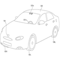
도 1은 본 발명의 실시예에 따른 차량의 외관을 도시한 도면이다.1 is a view showing an appearance of a vehicle according to an embodiment of the present invention.
도 1을 참조하면, 차량(500)은, 동력원에 의해 회전하는 바퀴(10FR,10FL,10RL,..), 차량(500)의 진행 방향을 조절하기 위한 조향 입력 수단(521a), 및 차량(500)에 부착되는 적어도 하나의 레이더 장치(100)를 구비할 수 있다.1, a
도 1에서, 레이더 장치(100)는 차량 전방에 단수로 부착되는 것으로 예시하나, 복수로 부착될 수 있으며, 차량의 후방 또는 측방에 부착될 수도 있다.In Fig. 1, the
도 2a 내지 도 2b는 본 발명의 실시예에 따른 레이더 장치의 블럭도이다.2A and 2B are block diagrams of a radar apparatus according to an embodiment of the present invention.
도 2a를 참조하면, 레이더 장치는 송신부(110), 제1 수신부(120), 제2 수신부(130), 메모리(140), 인터페이스부(150), 프로세서(180) 및 전원 공급부(190)를 포함할 수 있다.2A, a radar apparatus includes a transmitting
송신부(110)는, 송신 신호를 송출한다. 송신부(110)는 오실레이터(Oscillator), 송신 증폭기 및 송신 안테나(115)를 포함할 수 있다.The
오실레이터는 VCO(Voltage Control Oscillator) 등의 발진 소자로서, 신호를 생성할 수 있다. 한편, 실시예에 따라, 오실레이터는 복수로 구비될 수 있다. The oscillator is a oscillation element such as a VCO (Voltage Control Oscillator) and can generate a signal. Meanwhile, according to the embodiment, a plurality of oscillators may be provided.
예를 들면, 오실레이터는 FMCW(Frequency Modulated Continous Wave)의 파형을 생성하거나, 모노 펄스(Mono Pulse)의 파형을 생성할 수 있다. 예를 들면, 복수의 오실레이터가 구비되는 경우, 제1 오실레이터는 FMCW(Frequency Modulated Continous Wave)의 파형을 생성하고, 제2 오실레이터는 모노 펄스(Mono Pulse)의 파형을 생성할 수 있다.For example, an oscillator can generate a waveform of a frequency modulated continuous wave (FMCW) or a waveform of a mono pulse. For example, when a plurality of oscillators are provided, the first oscillator may generate a waveform of a Frequency Modulated Continuous Wave (FMCW), and the second oscillator may generate a waveform of a mono pulse.
송신 증폭기는, 증폭 회로를 포함하며, 오실레이터에서 생성된 신호를 증폭할 수 있다.The transmission amplifier includes an amplification circuit, and can amplify the signal generated in the oscillator.
송신 안테나(115)는, 오실레이터에서 생성된 신호 또는 송신 증폭기에서 증폭된 신호를 송신한다.The
송신부(110)는, 실시예에 따라, 삼각파 발생부를 더 포함할 수 있다.The transmitting
제1 수신부(120)는, 제1 수신 신호를 획득한다. 여기서, 제1 수신 신호는 송신 신호가 오브젝트에 반사되어 되돌아오는 신호이다.The first
제1 수신부(120)는, 제1 수신 안테나(125), 제1 믹서, 제1 증폭기, 제1 필터를 포함할 수 있다.The
제1 수신 안테나(125)는 송신 신호가 오브젝트에 반사되는 제1 수신 신호를 수신할 수 있다.The first receiving
제1 믹서는 오실레이터에서 생성된 신호와 제1 수신 안테나(125)에서 수신된 신호를 상관 연산하여 두 신호의 차이를 출력할 수 있다.The first mixer can output the difference between the two signals by performing a correlation operation between the signal generated by the oscillator and the signal received by the
제1 필터는 제1 믹서에서 수신된 신호를 필터링 할 수 있다.The first filter may filter the received signal at the first mixer.
제1 수신 증폭기는 제1 수신 안테나(125)에서 수신되는 신호, 제1 믹서 또는 제1 필터에서 수신되는 신호를 증폭할 수 있다.The first receiving amplifier may amplify the signal received at the
제2 수신부(130)는 제2 수신 신호를 획득한다. 여기서, 제2 수신 신호는 송신 신호가 오브젝트에 반사되어 되돌아오는 신호이다.The
제2 수신부(130)는, 제2 수신 안테나(135), 제2 믹서, 제2 증폭기, 제2 필터를 포함할 수 있다.The
제2 수신 안테나(135)는 송신 신호가 오브젝트에 반사되는 제2 수신 신호를 수신할 수 있다.And the
제2 믹서는 오실레이터에서 생성된 신호와 제2 수신 안테나(135)에서 수신된 신호를 상관 연산하여 두 신호의 차이를 출력할 수 있다.The second mixer may output the difference between the two signals by correlating the signal generated by the oscillator and the signal received by the
제2 필터는 제2 믹서에서 수신된 신호를 필터링 할 수 있다.The second filter may filter the received signal at the second mixer.
제2 수신 증폭기는 제2 수신 안테나(135)에서 수신되는 신호, 제2 믹서 또는 제2 필터에서 수신되는 신호를 증폭할 수 있다.The second receiving amplifier may amplify the signal received at the
메모리(140)는, 프로세서(180)의 처리 또는 제어를 위한 프로그램 등, 레이더 장치(100) 전반의 동작을 위한 다양한 데이터를 저장할 수 있다. 메모리(140)는, 하드웨어적으로, ROM, RAM, EPROM, 플래시 드라이브, 하드 드라이브 등과 같은 다양한 저장기기 일 수 있다.The
인터페이스부(150)는, 레이더 장치(100)에 연결되는 장치와 데이터를 교환하는 통로 역활을 수행할 수 있다. 인터페이스부(150)는 전기적으로 연결된 유닛으로부터 데이터를 수신하고, 프로세서(180)에서 처리 또는 생성되는 신호를 전기적으로 연결된 유닛으로 전송할 수 있다. 인터페이스부(150)는 ECU(580)와 데이터를 교환하는 통로 역할을 수행할 수 있다.The
프로세서(180)는, 레이더 장치(100) 내의 각 유닛의 전반적인 동작을 제어할 수 있다.The
프로세서(180)는, 하드웨어적으로, ASICs (application specific integrated circuits), DSPs(digital signal processors), DSPDs(digital signal processing devices), PLDs(programmable logic devices), FPGAs(field programmable gate arrays), 프로세서(processors), 제어기(controllers), 마이크로 컨트롤러(micro-controllers), 마이크로 프로세서(microprocessors), 기타 기능 수행을 위한 전기적 유닛 중 적어도 하나를 이용하여 구현될 수 있다.The
프로세서(180)의 상세 구성 및 각 구성의 동작에 대한 설명은 도 3을 참조하여 설명한다.The detailed configuration of the
전원 공급부(190)는, 프로세서(180)의 제어에 의해, 각 유닛들의 동작에 필요한 전원을 공급할 수 있다. 특히, 전원 공급부(190)는, 차량(500) 내부의 배터리 등으로부터 전원을 공급받을 수 있다.The power supply unit 190 can supply power necessary for operation of each unit under the control of the
도 2b는 도 2a의 레이더 장치(100)에 비해 자세 감지부(170) 및 자세 조정부(175)를 더 포함한다. 이하, 자세 감지부(150)를 중심으로 설명한다. 2B further includes a
자세 감지부(170)는 레이더 장치(100)의 자세를 감지할 수 있다. 레이더 장치(100)는, 차량 전방, 후방 또는 측방에 위치하는 오브젝트를 향해 송신 신호를 송출하고, 오브젝트에 반사되는 수신 신호를 획득하기 위해, 적합한 자세를 취해야 한다. 외부의 충격 등으로 인해, 레이더 장치(100)의 자세가 변한 경우, 자세 감지부(170)는 레이더 장치(100)의 자세의 변화를 감지한다.The
자세 감지부(170)는 레이더 장치(100)의 자세를 감지하기 위해, 적외선 센서, 볼트 체결 센서(예를 들면, Bolt Magnet 센서) 및 자이로 센서 중 적어도 하나를 포함할 수 있다.The
자세 조정부(175)는 자세 감지부(170)에서 감지한 자세에 기초하여, 레이더 장치(100)의 자세를 조정한다. 자세 조정부(175)는 모터 등의 구동 수단을 포함하고, 프로세서(180)의 제어에 따라, 송신 신호 송출 및 수신 신호 획득에 적합하도록, 레이더 장치(100)의 자세를 조정한다.The
프로세서(180)는 자세 감지부(170)로부터 감지된 자세 정보를 수신한다. 프로세서(180)는 수신된 자세 정보를 기초로, 자세 조정부(175)를 제어한다. The
실시예에 따라, 프로세서(180)는 레이더 장치(100)의 자세를 유지한 상태에서, 송신 신호에서 빔의 방향 및 크기를 제어할 수 있다. 송신 안테나(115)는 복수의 패치 안테나로 구성될 수 있고, 프로세서(180)는 각각의 패치 안테나의 출력을 제어하여, 전체적인 송출 빔의 방향 및 크기를 제어할 수 있다. 이경우, 레이더 장치(100)의 자세를 조정하는 것과 동일한 효과가 발생될 수 있다. 마찬가지 방법으로, 프로세서(180)는 수신 안테나(125, 135)를 제어할 수 있다.According to the embodiment, the
한편, 프로세서(180)는 자세 감지부(170)를 통해 감지된 안테나 장치(100)의 자세에 변화가 발생하는 경우, 인터페이스부(150)를 통해, ECU(도 11의 580)에 관련 정보를 전송할 수 있다. 이경우, ECU(580)는 출력부(도 11의 540)를 통해, 사용자가 인지할 수 있도록 안테나 장치(100)의 자세 변화 정보를 출력할 수 있다.When a change in the posture of the
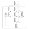
도 3은 본 발명의 실시예에 따른 프로세서의 상세 블럭도이다.3 is a detailed block diagram of a processor according to an embodiment of the present invention.
도 3을 참조하면, 프로세서(180)는 제1 연산부(305), 제2 연산부(310), Bi-static TOA 드로잉부(315), 제1 각도 연산부(320), 제2 각도 연산부(325), 제1 포인트 추출부(332), 제2 포인트 추출부(334), 포인트 확인부(336), 제3 각도 연산부(340), 판단부(350) 및 오브젝트 위치 결정부(360)를 포함할 수 있다.3, the
제1 연산부(305)는, 제1 수신부(120)에서 획득되는 제1 수신 신호를 바탕으로, 제1 업 비트 주파수, 제1 다운 비트 주파수를 검출한다. 여기서, 비트 주파수(Beat Frequency)는 송신 신호와 수신 신호의 주파수 차이로 표현되는 주파수이다. 업 비트 주파수(Up-Beat Frequency)는 업 첩(Up chirp)에 해당하는 비트 주파수이다. 다운 비트 주파수(Down-Beat Frequency)는 다운 첩(Down chirp)에 해당하는 비트 주파수이다.The first calculation unit 305 detects the first up-bit frequency and the first down-bit frequency based on the first reception signal obtained by the
제1 연산부(305)는 제1 업 비트 주파수 및 제1 다운 비트 주파수를 바탕으로, 제1 거리 비트 주파수 및 제1 도플러 주파수를 연산한다. 여기서, 거리 비트 주파수(Range Beat Frequency)와 도플러 주파수(Doppler Frequency)는 업 비트 주파수와 다운 비트 주파수에 포함된 이동하는 오브젝트의 거리와 상대적인 속도에 의한 주파수 이동(Freqeuncy Shifts) 성분이다.The first calculation unit 305 calculates the first distance bit frequency and the first Doppler frequency based on the first up-bit frequency and the first down-bit frequency. Here, the Range Beat Frequency and the Doppler Frequency are freqeuncy shifts due to the relative distance and the distance of the moving object included in the up bit frequency and the down bit frequency.
제1 연산부(305)는 제1 거리 비트 주파수 및 제1 도플러 주파수를 기초로, 오브젝트와의 제1 거리 정보 및 제1 속도 정보를 획득한다. 이경우, 제1 연산부(305)는 주파수 변조 연속파(FMCW, Frequency-Modulated Continuous Wave) 레이더에서 오브젝트와의 거리 및 속도를 구하는 수학식을 통해, 제1 거리 정보 및 제1 속도 정보를 획득할 수 있다.The first calculation unit 305 acquires the first distance information and the first speed information based on the first distance bit frequency and the first Doppler frequency. In this case, the first calculation unit 305 can acquire the first distance information and the first speed information through a mathematical expression for obtaining the distance and speed from the object in the frequency-modulated continuous wave (FMCW) radar .
제2 연산부(310)는, 제2 수신부(130)에서 획득되는 제2 수신 신호를 바탕으로, 제2 업 비트 주파수, 제2 다운 비트 주파수를 검출한다. 여기서, 비트 주파수(Beat Frequency)는 송신 신호와 수신 신호의 주파수 차이로 표현되는 주파수이다. 업 비트 주파수(Up-Beat Frequency)는 업 첩(Up chirp)에 해당하는 비트 주파수이다. 다운 비트 주파수(Down-Beat Frequency)는 다운 첩(Down chirp)에 해당하는 비트 주파수이다.The
제2 연산부(310)는 제2 업 비트 주파수 및 제2 다운 비트 주파수를 바탕으로, 제2 거리 비트 주파수 및 제2 도플러 주파수를 연산한다. 여기서, 거리 비트 주파수(Range Beat Frequency)와 도플러 주파수(Doppler Frequency)는 업 비트 주파수와 다운 비트 주파수에 포함된 이동하는 오브젝트의 거리와 상대적인 속도에 의한 주파수 이동(Freqeuncy Shifts) 성분이다.The
제2 연산부(310)는 제2 거리 비트 주파수 및 제2 도플러 주파수를 기초로, 오브젝트와의 제2 거리 정보 및 제2 속도 정보를 획득한다. 이경우, 제2 연산부(310)는 주파수 변조 연속파(FMCW, Frequency-Modulated Continuous Wave) 레이더에서 오브젝트와의 거리 및 속도를 구하는 수학식을 통해, 제2 거리 정보 및 제2 속도 정보를 획득할 수 있다.The
한편, 업 비트 주파수, 다운 비트 주파수, 거리 비트 주파수, 도플러 주파수거리 정보 및 속도 정보 획득 관련하여, 도 4 내지 도 7을 참조하여 상세하게 설명한다.On the other hand, regarding up-bit frequency, down-bit frequency, distance bit frequency, Doppler frequency distance information, and speed information acquisition, will be described in detail with reference to FIGS.
Bi-static TOA 드로잉부(315)는, North-referenced 좌표 시스템에서, 제1 및 제2 거리 정보를 기초로 오브젝트가 위치할 수 있는 예상 지점에 윤곽선(contour)를 드로잉(drawing)한다. 구체적으로, Bi-static TOA 드로잉부(315)는 제1 거리 정보에 기초한 제1 윤곽선 및 제2 거리 정보에 기초한 제2 윤곽선을 드로잉한다. The Bi-static
제1 각도 연산부(320)는, 제1 도플러 주파수 및 제1 속도 정보를 기초로, 제1 각도를 연산할 수 있다. 여기서, 제1 각도는 송신 안테나(115)와 제1 수신 안테나(125)가 오브젝트를 중심으로 이루는 각도일 수 있다. 제1 각도 연산부(320)는 Bi-static 레이더에서 도플러 주파수를 구하는 수학식을 통해, 제1 각도를 연산할 수 있다.The first angle calculator 320 can calculate the first angle based on the first Doppler frequency and the first velocity information. Here, the first angle may be an angle formed by the transmitting
제2 각도 연산부(325)는 제2 도플러 주파수 및 제2 속도 정보를 기초로, 제2 각도를 연산할 수 있다. 여기서, 제2 각도는 송신 안테나(115)와 제2 수신 안테나(135)가 오브젝트를 중심으로 이루는 각도일 수 있다. 제2 각도 연산부(320)는 Bi-static 레이더에서 도플러 주파수를 구하는 수학식을 통해, 제2 각도를 연산할 수 있다.The second angle calculator 325 can calculate the second angle based on the second Doppler frequency and the second velocity information. Here, the second angle may be an angle formed by the transmitting
제1 포인트 추출부(332)는 제1 각도를 통해, 2개의 오브젝트 위치 예상 포인트를 추출할 수 있다. 구체적으로, North-referenced 좌표 시스템에서, 제1 윤곽선 상에서 제1 각도를 통해 도출되는 오브젝트가 위치하는 예상 포인트는 2개일 수 있다. 이는, 오브젝트와의 제1 거리 정보 및 제1 각도에 기초하여 예상 포인트를 추출하기 때문이다. 이때, 실제 오브젝트를 리얼 타겟으로, 가상의 오브젝트를 고스트 타겟으로 명명할 수 있다.The first point extracting unit 332 can extract two object position estimation points through the first angle. Specifically, in the North-referenced coordinate system, the expected point at which the object derived through the first angle on the first contour is located may be two. This is because the predicted point is extracted based on the first distance information and the first angle with the object. At this time, it is possible to designate a real object as a real target and a virtual object as a ghost target.
제2 포인트 추출부(334)는 제2 각도를 통해, 2개의 오브젝트 위치 예상 포인트를 추출할 수 있다. 구체적으로, North-referenced 좌표 시스템에서, 제2 윤곽선 상에서 제2 각도를 통해 도출되는 오브젝트가 위치하는 예상 포인트는 2개일 수 있다. 이는, 오브젝트와의 제2 거리 정보 및 제2 각도에 기초하여 예상 포인트를 추출하기 때문이다. 이때, 실제 오브젝트를 리얼 타겟으로, 가상의 오브젝트를 고스트 타겟으로 명명할 수 있다.The second
포인트 확인부(336)는 제1 각도를 통해 추출된 예상 포인트 및 제2 각도를 통해 추출된 예상 포인트를 비교하여, 공통 포인트를 추출한다. 구체적으로, 제1 포인트 추출부(332)가 추출한 2개의 오브젝트 위치 예상 포인트와 제2 포인트 추출부(332)가 추출한 2개의 오브젝트 위치 예상 포인트에서, 포인트 확인부(336)는 1개의 공통 포인트를 추출한다. 실제로 오브젝트는 1개이므로, 제1 포인트 추출부(332) 및 제2 포인트 추출부(334)에서 추출된 예상 포인트에서 공통 포인트가 존재하고, 포인트 확인부(336)는 공통 포인트를 추출한다.The
포인트 확인부(336)는 추출된 공통 포인트를 오브젝트의 위치로 확인할 수 있다.The
제3 각도 연산부(340)는, 제1 및 제2 수신 신호간의 위상차(Phase Difference)를 기초로, 제3 각도를 연산할 수 있다. 여기서, 제3 각도는 제1 또는 제2 수신 안테나(135)의 지향 방향을 향해 수직으로 이어지는 가상의 중심선과 제1 또는 제2 수신 안테나(135)에서 오브젝트를 잇는 가상의 선이 이루는 각도일 수 있다. 제3 각도 연산부(340)는 송신부(110)에서 송출된 송신 신호가 오브젝트에 반사되어 제1 수신부(120) 및 제2 수신부(130)에서 제1 및 제2 수신 신호가 획득될 때, 오브젝트에서 제1 수신 안테나 및 제2 수신 안테나(125, 135)까지의 거리에 따른 경로차에 의해 발생되는 위상차를 이용하여, 제3 각도를 연산할 수 있다.The
판단부(350)는, 제3 각도 연산부(340)에서 제3 각도가 획득되는지 판단할 수 있다. 또한, 판단부(350)는 제3 각도가 임계값 이상인지 판단할 수 있다. 여기서, 임계값은, 시간의 흐름에 따라 획득되는 복수의 제3 각도를 트래킹하여 결정될 수 있다. 예를 들어, 트래킹되는 제3 각도가 플러스 마이너스 5° 범위에 있다가, 일시에 90°이상 차이는 경우, 판단부(350)는 제3 각도가 임계값 이상인 것으로 판단할 수 있다.The determination unit 350 may determine whether the third angle is obtained in the third
오브젝트 위치 결정부(360)는, 제1 내지 제3 각도를 비교하여, 오브젝트의 위치를 결정할 수 있다. 오브젝트 위치 결정부(360)는 제1 내지 제3 각도를 비교하여, 송신 안테나(115)로부터 송출 방향을 향해 수직으로 이어지는 가상의 중심선을 기준으로 오브젝트가 좌측 또는 우측 방향으로 벗어난 각도를 결정할 수 있다.The object position determination unit 360 can determine the position of the object by comparing the first to third angles. The object position determination unit 360 may compare the first to third angles and determine an angle at which the object deviates leftward or rightward with respect to a virtual center line extending vertically from the
판단부(350)에서 판단한 결과, 제3 각도가 획득되지 않는 경우, 오브젝트 위치 결정부(360)는 제1 및 제2 각도만을 비교하여 오브젝트의 위치를 확정할 수 있다.As a result of the determination by the determination unit 350, when the third angle is not obtained, the object position determination unit 360 can determine the position of the object by comparing only the first and second angles.
판단부(350)에서 판단한 결과, 제3 각도가 임계값 이상인 경우, 오브젝트 위치 결정부(360)는 제1 및 제2 각도만을 비교하여 오브젝트의 위치를 확정할 수 있다.As a result of the determination by the determination unit 350, when the third angle is equal to or greater than the threshold value, the object position determination unit 360 can determine the position of the object by comparing only the first and second angles.
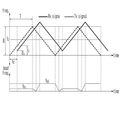
도 4는 본 발명의 실시예에 따른 송신 신호의 일예를 설명하는데 참조되는 도면이다.4 is a diagram for explaining an example of a transmission signal according to an embodiment of the present invention.
도 4를 참조하면, 본 발명의 실시예에 따른 레이더 장치(100)는 도시된 바와 같은 삼각파 형상의 주파수 변조된 연속파를 송출할 수 있다.Referring to FIG. 4, the
도 4의 형태로 송출된 신호는 오브젝트에 반사되고, 레이더 장치(100)는 오브젝트에 반사되는 수신 신호를 획득한다. The signal transmitted in the form of FIG. 4 is reflected on the object, and the
레이더 장치(100)는 수신 신호와 송신 신호로 얻어지는 비트(beat) 신호(예를 들면, 수신 신호의 주파수와 송신 신호의 주파수 간의 차이를 나타내는 시간 영역 신호)의 주파수(이하, 비트 주파수) 스펙트럼을 분석하여, 오브젝트와의 거리 정보 및 속도 정보를 획득할 수 있다. 여기서, fc는 중심 주파수, f0는 시작 주파수, B는 변조 대역폭(Modulation Bandwidth), Tm은 변조 주기(Modulation Period)이다.The
도 5는 본 발명의 실시예에 따라 송신 주파수 및 수신 주파수를 도시한 도면이다.5 is a diagram illustrating a transmission frequency and a reception frequency according to an embodiment of the present invention.
도 5a 내지 5c는 송신 신호의 주파수(이하, 송신 주파수)와 수신 신호의 주파수(이하, 수신 주파수) 간의 관계를 시간 축 상에 나타내는 도면으로서, 도 5a는 물체가 정지해 있을 때, 도 5b는 물체가 레이더 장치에 가까워 질 때, 도 5c는 물체가 레이더 장치로부터 멀어질 때를 나타낸다.5A is a diagram showing a relationship between a frequency of a transmission signal (hereinafter referred to as a transmission frequency) and a frequency of a reception signal (hereinafter referred to as a reception frequency) on a time axis. When the object approaches the radar device, Figure 5c shows when the object is away from the radar device.
여기서, td는 송신 신호와 수신 신호 사이의 지연 시간으로, 물체와 레이더 장치 간의 거리에 의해 결정된다.Here, td is a delay time between the transmission signal and the reception signal, and is determined by the distance between the object and the radar device.
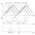
도 6은 본 발명의 실시예에 따른 비트 주파수를 설명하는데 참조되는 도면이다.6 is a diagram referred to explain bit frequencies according to an embodiment of the present invention.
도 6a 내지 도 6b는 송신 신호의 주파수와 수신 신호의 주파수 간의 관계 및 그에 따른 비트 주파수를 시간 축 상에 나타내는 도면으로서, 도 6a는 도 5a와 같은 정적인 상황에, 도 6b는 도 5b와 같은 동적인 상황에 대응된다. 여기서, 비트 주파수 fb는 송신 주파수와 수신 주파수 간의 차로서 구해진다.6A and 6B are diagrams showing the relationship between the frequency of the transmission signal and the frequency of the reception signal and the bit frequency according to the frequency, on the time axis. FIG. 6A is a diagram illustrating a static situation shown in FIG. 5A, FIG. It corresponds to a dynamic situation. Here, the bit frequency fb is obtained as a difference between the transmission frequency and the reception frequency.
도 6a와 같은 정적인 상황에서 비트 주파수는 물체와 레이더 장치 간의 거리에 따른 지연 시간에 의해 결정되는 반면, 도 6b와 같은 동적인 상황에서는 물체와 레이더 장치 간의 상대 속도의 변화가 있으므로, 도플러 주파수 편이 현상이 발생되기 때문에 비트 주파수는 거리 비트 주파수 fr과 도플러 주파수 fd의 조합으로 이루어진다. 따라서, 도 3b에 도시된 fbu와 fbd는 이러한 fr과 fd의 조합으로 구성된다.In the static situation as shown in FIG. 6A, the bit frequency is determined by the delay time depending on the distance between the object and the radar device, whereas in the dynamic situation as shown in FIG. 6B, since the relative speed between the object and the radar device changes, Since the phenomenon occurs, the bit frequency is a combination of the distance bit frequency fr and the Doppler frequency fd. Therefore, fbu and fbd shown in Fig. 3B are composed of a combination of fr and fd.
도 7은 본발명의 실시예에 따라, 비트 주파수를 이용한 거리 및 속도 검출 원리를 설명하기 위한 도면이다.7 is a diagram for explaining the principle of distance and velocity detection using a bit frequency according to an embodiment of the present invention.
비트(beat) 주파수는 업 첩(Up chirp)에 해당하는 업 비트 주파수(Up-Beat Frequency), 다운 첩(Down chirp)에 해당하는 다운 비트 주파수(Down-Beat Frequency)를 포함한다. 업 비트 주파수와 다운 비트 주파수에는 이동하는 타겟의 거리와 상대적인 속도에 의한 주파수 이동(Frequency Shifts) 성분이 포함된다. 이러한 성분들은 각각 거리 비트 주파수(Range Beat Frequency)와 도플러 주파수(Doppler Frequency)라고 하는데, 업 비트 주파수 및 다운 비트 주파수는 수학식 1 및 수학식 2와 같이 거리 비트 주파수와 도플러 주파수의 조합으로 나타낼 수 있다. The beat frequency includes an up-beat frequency corresponding to an up chirp and a down-beat frequency corresponding to a down chirp. The up beat frequency and the down beat frequency include frequency shifts by the distance of the moving target and the relative speed. These components are referred to as a range beat frequency and a Doppler frequency, respectively. The up bit frequency and the down bit frequency can be represented by a combination of a distance bit frequency and a Doppler frequency as shown in Equations (1) and (2) have.
수학식 1Equation 1
fbu = fr + fd
fbu = fr + fd
수학식 2
fbd = fr - fdfbd = fr - fd
fbu는 업 비트 주파수, fbd는 다운 비트 주파수, fr은 거리 비트 주파수, fd는 도플러 주파수 임
fbu is the up-bit frequency, fbd is the down-bit frequency, fr is the distance bit frequency, and fd is the Doppler frequency
음의 값을 가지는 도플러 주파수는 오브젝트가 레이더 장치(100)를 향해 다가오고 있음을 나타내고, 양의 값을 가지는 도플러 주파수는 오브젝트가 레이더 장치(100)로부터 멀어지고 있음을 나타낸다. 결국, 오브젝트와의 거리 및 속도는 거리 비트 주파수와 도플러 주파수를 이용하여 각각 계산될 수 있다.A negative Doppler frequency indicates that the object is approaching the
한편, 도 4 내지 도 7을 참조하여 설명한 수신 신호는 제1 수신부(120)에서 수신하는 제1 수신 신호 및 제2 수신부(130)에서 수신하는 제2 수신 신호에 해당된다.4 to 7 correspond to a first reception signal received by the
프로세서(180)의 제1 연산부(305)는, 제1 수신부(120)에서 획득되는 제1 수신 신호를 바탕으로, 제1 업 비트 주파수, 제1 다운 비트 주파수를 검출한다. The first calculation unit 305 of the
제1 연산부(305)는 제1 업 비트 주파수 및 제1 다운 비트 주파수를 바탕으로, 제1 거리 비트 주파수 및 제1 도플러 주파수를 연산한다. The first calculation unit 305 calculates the first distance bit frequency and the first Doppler frequency based on the first up-bit frequency and the first down-bit frequency.
제1 연산부(305)는 제1 거리 비트 주파수 및 제1 도플러 주파수를 기초로, 오브젝트와의 제1 거리 정보 및 제1 속도 정보를 획득한다. 이경우, 제1 연산부(305)는 주파수 변조 연속파(FMCW, Frequency-Modulated Continuous Wave) 레이더에서 오브젝트와의 거리 및 속도를 구하는 수학식을 통해, 제1 거리 정보 및 제1 속도 정보를 획득할 수 있다.The first calculation unit 305 acquires the first distance information and the first speed information based on the first distance bit frequency and the first Doppler frequency. In this case, the first calculation unit 305 can acquire the first distance information and the first speed information through a mathematical expression for obtaining the distance and speed from the object in the frequency-modulated continuous wave (FMCW) radar .
프로세서(180)의 제2 연산부(310)는, 제2 수신부(130)에서 획득되는 제2 수신 신호를 바탕으로, 제2 업 비트 주파수, 제2 다운 비트 주파수를 검출한다. The second
제2 연산부(310)는 제2 업 비트 주파수 및 제2 다운 비트 주파수를 바탕으로, 제2 거리 비트 주파수 및 제2 도플러 주파수를 연산한다. The
제2 연산부(310)는 제2 거리 비트 주파수 및 제2 도플러 주파수를 기초로, 오브젝트와의 제2 거리 정보 및 제2 속도 정보를 획득한다. 이경우, 제2 연산부(310)는 주파수 변조 연속파(FMCW, Frequency-Modulated Continuous Wave) 레이더에서 오브젝트와의 거리 및 속도를 구하는 수학식을 통해, 제2 거리 정보 및 제2 속도 정보를 획득할 수 있다.The
도 8은 본 발명의 실시예에 따라, 제1 및 제2 각도를 통해 공통 포인트를 추출하는 동작을 설명하는데 참조되는 도면이다.Figure 8 is a diagram that is referenced to illustrate the operation of extracting common points through first and second angles, in accordance with an embodiment of the present invention.
도 8을 참조하면, 프로세서(180)의 Bi-static TOA 드로잉부(315)는, 제1 거리 정보(Rt, Rr1)에 기초하여 제1 윤곽선(810)을 드로잉한다. 또한, Bi-static TOA 드로잉부(315)는, 제2 거리 정보(Rt, Rr2)에 기초하여 제2 윤곽선(840)을 드로잉한다.8, the Bi-static
한편, 프로세서(180)의 제1 각도 연산부(320)는, 제1 도플러 주파수 및 제1 속도 정보를 기초로, 제1 각도(θ1)를 연산할 수 있다. 여기서, 제1 각도(θ1)는 송신 안테나(115)와 제1 수신 안테나(125)가 오브젝트를 중심으로 이루는 각도일 수 있다. 제1 각도 연산부(320)는 Bi-static 레이더에서 도플러 주파수를 구하는 수학식을 통해, 제1 각도(θ1)를 연산할 수 있다.On the other hand, the first angle calculator 320 of the
프로세서(180)의 제2 각도 연산부(325)는 제2 도플러 주파수 및 제2 속도 정보를 기초로, 제2 각도(θ2)를 연산할 수 있다. 여기서, 제2 각도(θ2)는 송신 안테나(115)와 제2 수신 안테나(135)가 오브젝트를 중심으로 이루는 각도일 수 있다. 제2 각도 연산부(320)는 Bi-static 레이더에서 도플러 주파수를 구하는 수학식을 통해, 제2 각도(θ2)를 연산할 수 있다.The second angle calculator 325 of the
프로세서(180)의 제1 포인트 추출부(332)는 제1 각도(θ1)를 통해, 2개의 오브젝트 위치 예상 포인트(820, 830)를 추출할 수 있다. 구체적으로, North-referenced 좌표 시스템에서, 제1 윤곽선(810) 상에서 제1 각도를 통해 도출되는 오브젝트가 위치하는 예상 포인트는 2개(820, 830)일 수 있다. 이는, 오브젝트와의 제1 거리 정보(Rt, Rr1) 및 제1 각도(θ1)에 기초하여 예상 포인트(820, 830)를 추출하기 때문이다. 이때, 실제 오브젝트(820)를 리얼 타겟으로, 가상의 오브젝트(830)를 고스트 타겟으로 명명할 수 있다.The first point extractor 332 of the
프로세서(180)의 제2 포인트 추출부(334)는 제2 각도(θ2)를 통해, 2개의 오브젝트 위치 예상 포인트(820, 850)를 추출할 수 있다. 구체적으로, North-referenced 좌표 시스템에서, 제2 윤곽선(840) 상에서 제2 각도(θ2)를 통해 도출되는 오브젝트가 위치하는 예상 포인트는 2개(820, 850)일 수 있다. 이는, 오브젝트와의 제2 거리 정보(Rt, Rr2) 및 제2 각도(θ2)에 기초하여 예상 포인트를 추출하기 때문이다. 이때, 실제 오브젝트(820)를 리얼 타겟으로, 가상의 오브젝트를 고스트 타겟(850)으로 명명할 수 있다.The second
프로세서(180)의 포인트 확인부(336)는 제1 각도(θ1)를 통해 추출된 예상 포인트(820, 830) 및 제2 각도(θ2)를 통해 추출된 예상 포인트(820, 850)를 비교하여, 공통 포인트(820)를 추출한다. 구체적으로, 제1 포인트 추출부(332)가 추출한 2개의 오브젝트 위치 예상 포인트(820, 830)와 제2 포인트 추출부(332)가 추출한 2개의 오브젝트 위치 예상 포인트(820, 850)에서, 포인트 확인부(336)는 1개의 공통 포인트(820)를 추출한다. 실제로 오브젝트는 1개이므로, 제1 포인트 추출부(332) 및 제2 포인트 추출부(334)에서 추출된 예상 포인트에서 공통 포인트(820)가 존재하고, 포인트 확인부(336)는 공통 포인트(820)를 추출한다.The
포인트 확인부(336)는 추출된 공통 포인트(820)를 오브젝트의 위치로 확인할 수 있다.The
도 9는 본 발명의 실시예에 따라 제3 각도를 연산하는 동작을 설명하는데 참조되는 도면이다.9 is a diagram referred to explain an operation of computing a third angle according to an embodiment of the present invention.
도 9를 참조하면, 프로세서(180)의 제3 각도 연산부(340)는, 제1 및 제2 수신 신호간의 위상차(Phase Difference)를 기초로, 제3 각도(θ3)를 연산할 수 있다. 여기서, 제3 각도(θ3)는 레이더 장치(100)의 지향 방향을 향해 수직으로 이어지는 가상의 중심선과 송신 안테나(115), 제1 안테나(125) 또는 제2 수신 안테나(135)에서 오브젝트(910)를 잇는 가상의 선이 이루는 각도일 수 있다. Referring to FIG. 9, the
한편, 레이더 장치(100)에서 오브젝트(910)까지의 거리에 비하면, 레이더 장치(100)에 포함되는 송신 안테나(115), 제1 안테나(125), 제2 안테나(135) 사이의 거리는 무시할 수 있다. The distance between the transmitting
제3 각도 연산부(340)는 송신 안테나부(115)에서 송출된 송신 신호가 오브젝트(910)에 반사되어 제1 수신 안테나(125) 및 제2 수신 안테나(135)에서 제1 및 제2 수신 신호가 획득될 때, 오브젝트(910)에서 제1 수신 안테나 및 제2 수신 안테나(125, 135)까지의 거리에 따른 경로차에 의해 발생되는 위상차(920)를 이용하여, 제3 각도(θ3)를 연산할 수 있다.The
도 10은 본 발명의 실시예에 따른 레이더 장치의 동작을 설명하는 플로우 차트이다.10 is a flowchart illustrating the operation of the radar apparatus according to the embodiment of the present invention.
도 10을 참조하면, 송신부(110)는, 송신 신호를 송출한다(S1110). Referring to Fig. 10, the
송신 신호가 송출된 후, 제1 수신부(120)는 제1 수신 신호를 획득하고, 제2 수신부(130)는 제2 수신 신호를 획득한다(S1120). 여기서, 제1 및 제2 수신 신호는 송신 신호가 오브젝트에 반사되어 되돌아오는 신호이다.After the transmission signal is transmitted, the
제1 수신 신호가 획득된 상태에서, 프로세서(180)의 제1 연산부(305)는 제1 수신 신호를 바탕으로, 제1 업 비트 주파수, 제1 다운 비트 주파수를 검출한다. 제1 연산부(305)는 제1 업 비트 주파수 및 제1 다운 비트 주파수를 바탕으로, 제1 거리 비트 주파수 및 제1 도플러 주파수를 연산한다(S1130).With the first received signal obtained, the first calculating unit 305 of the
또한, 제2 수신 신호가 획득된 상태에서, 프로세서(180)의 제2 연산부(310)는 제2 수신 신호를 바탕으로, 제2 업 비트 주파수, 제2 다운 비트 주파수를 검출한다. 제2 연산부(310)는 제2 업 비트 주파수 및 제2 다운 비트 주파수를 바탕으로, 제2 거리 비트 주파수 및 제2 도플러 주파수를 연산한다(S1130).Further, in a state where the second reception signal is acquired, the
제1 거리 비트 주파수 및 제1 도플러 주파수가 연산된 상태에서, 프로세서(180)의 제1 연산부(305)는 제1 거리 비트 주파수 및 제1 도플러 주파수를 기초로, 오브젝트와의 제1 거리 정보 및 제1 속도 정보를 획득한다(S1140).With the first distance bit frequency and the first Doppler frequency calculated, the first arithmetic section 305 of the
또한, 제2 거리 비트 주파수 및 제2 도플러 주파수가 연산된 상태에서, 프로세서(180)의 제2 연산부(310)는 제2 거리 비트 주파수 및 제2 도플러 주파수를 기초로, 오브젝트와의 제2 거리 정보 및 제2 속도 정보를 획득한다(S1140).Further, in a state where the second distance bit frequency and the second Doppler frequency are calculated, the second calculating
이후에, 프로세서(180)의 제1 각도 연산부(320)는 제1 도플러 주파수 및 제1 속도 정보를 기초로, 제1 각도를 연산한다(S1150). 여기서, 제1 각도는 송신 안테나(115)와 제1 수신 안테나(125)가 오브젝트를 중심으로 이루는 각도일 수 있다.Thereafter, the first angle calculator 320 of the
또한, 프로세서(180)의 제2 각도 연산부(325)는 제2 도플러 주파수 및 제2 속도 정보를 기초로, 제2 각도를 연산한다(S1150). 여기서, 제2 각도는 송신 안테나(115)와 제2 수신 안테나(135)가 오브젝트를 중심으로 이루는 각도일 수 있다.In addition, the second angle calculator 325 of the
한편, 제3 각도 연산부(340)는 제1 및 제2 수신 신호간의 위상차(Phase Difference)를 기초로, 제3 각도를 연산한다(S1160). 여기서, 제3 각도는 제1 또는 제2 수신 안테나(135)의 지향 방향을 향해 수직으로 이어지는 가상의 중심선과 제1 또는 제2 수신 안테나(135)에서 오브젝트를 잇는 가상의 선이 이루는 각도일 수 있다.On the other hand, the
제3 각도 연산 동작(S1160)은 제1 및 제2 각도 연산 동작(1150) 이후에 수행되는 것으로 설명되나, 이에 한정되지 않고, 제3 각도 연산 동작(S1160)은 제1 및 제2 수신 신호 획득 동작(S1120)이후에 수행될 수 있다.Although the third angle calculation operation S1160 is described as being performed after the first and second angle calculation operations 1150, the third angle calculation operation S1160 is not limited to this, May be performed after operation S1120.
이후에, 프로세서(180)의 판단부(350)는 제3 각도 연산부(340)에서 제3 각도가 획득되지 않거나, 제3 각도가 획득되는 경우, 제3 각도가 임계값 이상인지 판단한다(S1170). 여기서, 임계값은, 시간의 흐름에 따라 획득되는 복수의 제3 각도를 트래킹하여 결정될 수 있다.If the third angle is not obtained or the third angle is acquired in the
만약, 제3 각도가 획득되지 않거나, 제3 각도가 획득된 경우, 획득된 제3 각도가 임계값 이상인 경우, 오브젝트 위치 결정부(360)는 제1 내지 제2 각도를 비교하여 오브젝트의 위치를 확정한다(S1180).If the third angle is not obtained or the third angle is obtained and the obtained third angle is greater than or equal to the threshold value, the object position determination unit 360 compares the first and second angles to determine the position of the object (S1180).
만약, 제3 각도가 획득되고, 획득된 제3 각도가 임계값보다 작은 경우, 오브젝트 위치 결정부(360)는 제1 내지 제3 각도를 비교하여, 오브젝트의 위치를 결정한다(S1190).If the third angle is obtained and the obtained third angle is smaller than the threshold value, the object position determination unit 360 compares the first to third angles to determine the position of the object (S1190).
도 11은 본 발명의 실시예에 따른 차량의 블럭도이다.11 is a block diagram of a vehicle according to an embodiment of the present invention.
도 11을 참조하면, 차량(500)은 통신부(510), 입력부(520), 센싱부(530), 출력부(540), 차량 구동부(550), 메모리(560), 인터페이스부(570), ECU(580), 전원부(590) 및 레이더 장치(100)를 포함할 수 있다.11, the
통신부(510)는, 차량(500)과 이동 단말기(200a, 200b, 200c) 사이, 차량(500)과 외부 서버(410) 사이 또는 차량(500)과 타차량(420)과의 무선 통신을 가능하게 하는 하나 이상의 모듈을 포함할 수 있다. 또한, 통신부(510)는 차량(500)을 하나 이상의 망(network)에 연결하는 하나 이상의 모듈을 포함할 수 있다.The
통신부(510)는, 무선 인터넷 모듈(512), 근거리 통신 모듈(513), 위치 정보 모듈(514) 및 광통신 모듈(515)을 포함할 수 있다.The
무선 인터넷 모듈(512)은, 무선 인터넷 접속을 위한 모듈을 말하는 것으로, 차량(500)에 내장되거나 외장될 수 있다. 무선 인터넷 모듈(512)은 무선 인터넷 기술들에 따른 통신망에서 무선 신호를 송수신하도록 이루어진다.The
무선 인터넷 기술로는, 예를 들어 WLAN(Wireless LAN), Wi-Fi(Wireless-Fidelity), Wi-Fi(Wireless Fidelity) Direct, DLNA(Digital Living Network Alliance), WiBro(Wireless Broadband), WiMAX(World Interoperability for Microwave Access), HSDPA(High Speed Downlink Packet Access), HSUPA(High Speed Uplink Packet Access), LTE(Long Term Evolution), LTE-A(Long Term Evolution-Advanced) 등이 있으며, 상기 무선 인터넷 모듈(512)은 상기에서 나열되지 않은 인터넷 기술까지 포함한 범위에서 적어도 하나의 무선 인터넷 기술에 따라 데이터를 송수신하게 된다.Wireless Internet technologies include, for example, wireless LAN (WLAN), wireless fidelity (Wi-Fi), wireless fidelity (Wi-Fi) Direct, DLNA (Digital Living Network Alliance), WiBro Interoperability for Microwave Access, High Speed Downlink Packet Access (HSDPA), High Speed Uplink Packet Access (HSUPA), Long Term Evolution (LTE) and Long Term Evolution-Advanced (LTE-A) 512 transmit and receive data according to at least one wireless Internet technology, including Internet technologies not listed above.
근거리 통신 모듈(513)은, 근거리 통신(Short range communication)을 위한 것으로서, 블루투스(Bluetooth™), RFID(Radio Frequency Identification), 적외선 통신(Infrared Data Association; IrDA), UWB(Ultra Wideband), ZigBee, NFC(Near Field Communication), Wi-Fi(Wireless-Fidelity), Wi-Fi Direct, Wireless USB(Wireless Universal Serial Bus) 기술 중 적어도 하나를 이용하여, 근거리 통신을 지원할 수 있다. The short-
이러한, 근거리 통신 모듈(513)은, 근거리 무선 통신망(Wireless Area Networks)을 형성하여, 차량(500)과 적어도 하나의 외부 디바이스 사이의 근거리 통신을 수행할 수 있다.The short-
위치 정보 모듈(514)은, 차량(500)의 위치를 획득하기 위한 모듈로서, 그의 대표적인 예로는 GPS(Global Positioning System) 모듈 또는 WiFi(Wireless Fidelity) 모듈이 있다. 예를 들어, 차량은 GPS모듈을 활용하면, GPS 위성에서 보내는 신호를 이용하여 차량의 위치를 획득할 수 있다. 다른 예로서, 차량은 Wi-Fi모듈을 활용하면, Wi-Fi모듈과 무선신호를 송신 또는 수신하는 무선 AP(Wireless Access Point)의 정보에 기반하여, 차량의 위치를 획득할 수 있다. 필요에 따라서, 위치정보모듈(514)은 치환 또는 부가적으로 차량의 위치에 관한 데이터를 얻기 위해 통신부(510)의 다른 모듈 중 어느 기능을 수행할 수 있다. 위치 정보 모듈(514)은 차량의 위치(또는 현재 위치)를 획득하기 위해 이용되는 모듈로, 차량의 위치를 직접적으로 계산하거나 획득하는 모듈로 한정되지는 않는다.The
광통신 모듈(515)은, 광발신부 및 광수신부를 포함할 수 있다. The
광수신부는, 광(light)신호를 전기 신호로 전환하여, 정보를 수신할 수 있다. 광수신부는 광을 수신하기 위한 포토 다이오드(PD, Photo Diode)를 포함할 수 있다. 포토 다이오드는 빛을 전기 신호로 전환할 수 있다. 예를 들면, 광수신부는 전방 차량에 포함된 광원에서 방출되는 광을 통해, 전방 차량의 정보를 수신할 수 있다. The light receiving section can convert the light signal into an electric signal and receive the information. The light receiving unit may include a photodiode (PD) for receiving light. Photodiodes can convert light into electrical signals. For example, the light receiving section can receive information of the front vehicle through light emitted from the light source included in the front vehicle.
광발신부는 전기 신호를 광 신호로 전환하기 위한 발광 소자를 적어도 하나 포함할 수 있다. 여기서, 발광 소자는 LED(Light Emitting Diode)인 것이 바람직하다. 광발신부는, 전기 신호를 광 신호로 전환하여, 외부에 발신한다. 예를 들어, 광 발신부는 소정 주파수에 대응하는 발광소자의 점멸을 통해, 광신호를 외부에 방출할 수 있다. 실시예에 따라, 광발신부는 복수의 발광 소자 어레이를 포함할 수 있다. 실시예에 따라, 광발신부는 차량(500)에 구비된 램프와 일체화될 수 있다. 예를 들면, 광발신부는 전조등, 후미등, 제동등, 방향 지시등 및 차폭등 중 적어도 어느 하나일 수 있다.The light emitting unit may include at least one light emitting element for converting an electric signal into an optical signal. Here, the light emitting element is preferably an LED (Light Emitting Diode). The optical transmitter converts the electrical signal into an optical signal and transmits it to the outside. For example, the optical transmitter can emit the optical signal to the outside through the blinking of the light emitting element corresponding to the predetermined frequency. According to an embodiment, the light emitting portion may include a plurality of light emitting element arrays. According to the embodiment, the light emitting portion may be integrated with the lamp provided in the
입력부(520)는, 운전 조작 수단(521), 카메라(522), 마이크로 폰(523) 및 사용자 입력부(524)를 포함할 수 있다.The
운전 조작 수단(521)은, 차량(500) 운전을 위한 사용자 입력을 수신한다. 운전 조작 수단(521)은 조향 입력 수단(521a), 쉬프트 입력 수단(521b), 가속 입력 수단(521c), 브레이크 입력 수단(521d)을 포함할 수 있다. The driving operation means 521 receives a user input for driving the
조향 입력 수단(521a)은, 사용자로부터 차량(500)의 진행 방향 입력을 수신한다. 조향 입력 수단(521a)은 회전에 의해 조향 입력이 가능하도록 휠 형태로 형성되는 것이 바람직하다. 실시예에 따라, 조향 입력 수단(521a)은 터치 스크린, 터치 패드 또는 버튼으로 형성될 수도 있다.The steering input means 521a receives a forward direction input of the
쉬프트 입력 수단(521b)은, 사용자로부터 차량(500)의 주차(P), 전진(D), 중립(N), 후진(R)의 입력을 수신한다. 쉬프트 입력 수단(521b)은 레버 형태로 형성되는 것이 바람직하다. 실시예에 따라, 쉬프트 입력 수단(521b)은 터치 스크린, 터치 패드 또는 버튼으로 형성될 수도 있다.The shift input means 521b receives the input of parking (P), forward (D), neutral (N), and reverse (R) of the
가속 입력 수단(521c)은, 사용자로부터 차량(500)의 가속을 위한 입력을 수신한다. 브레이크 입력 수단(521d)은, 사용자로부터 차량(500)의 감속을 위한 입력을 수신한다. 가속 입력 수단(521c) 및 브레이크 입력 수단(521d)은 페달 형태로 형성되는 것이 바람직하다. 실시예에 따라, 가속 입력 수단(521c) 또는 브레이크 입력 수단(521d)은 터치 스크린, 터치 패드 또는 버튼으로 형성될 수도 있다.The acceleration input means 521c receives an input for acceleration of the
카메라(522)는, 이미지 센서와 영상 처리 모듈을 포함할 수 있다. 카메라(522)는 이미지 센서(예를 들면, CMOS 또는 CCD)에 의해 얻어지는 정지영상 또는 동영상을 처리할 수 있다. 영상 처리 모듈은 이미지 센서를 통해 획득된 정지영상 또는 동영상을 가공하여, 필요한 정보를 추출하고, 추출된 정보를 ECU(580)에 전달할 수 있다. 한편, 차량(500)은 차량 전방의 영상을 촬영하는 제1 카메라(521a) 및 차량 내부 영상을 촬영하는 제2 카메라(522b)를 포함할 수 있다.The
제1 카메라(522a)는 스테레오 카메라로 구성되어, 차량 전방의 스테레오 이미지를 획득할 수 있다. 이때, 영상 처리 모듈은, 시차정보(binocular parallax information)를 통해, 스테레오 이미지 상에서 검출되는 오브젝트와의 거리 정보를 제공할 수 있다.The
제2 카메라(522b)는 탑승자에 대한 이미지를 획득할 수 있다. 제2 카메라(522b)는 탑승자의 생체 인식을 위한 이미지를 획득할 수 있다.And the second camera 522b may acquire an image of the occupant. And the second camera 522b can acquire an image for biometrics of the passenger.
마이크로 폰(523)은, 외부의 음향 신호를 전기적인 데이터로 처리할 수 있다. 처리된 데이터는 차량(500)에서 수행 중인 기능에 따라 다양하게 활용될 수 있다. 마이크로폰(523)은 사용자의 음성 명령을 전기적인 데이터로 전환할 수 있다. 전환된 전기적인 데이터는 ECU(580)에 전달될 수 있다. The
한편, 실시예에 따라, 마이크로 폰(523)은 차량 사고 발생 시, 차량 사고 음향을 입력받을 수 있다. 여기서, 차량 사고 음향은 충돌음, 기 설정 시간 이상 지속되는 경적음, 노면과 타이어의 마찰음, 에어백 전개음 등일 수 있다. 마이크로 폰(523)은 차량 사고 음향을 전기적인 데이터로 전환하여 ECU(580)에 전달한다.Meanwhile, according to the embodiment, when the vehicle accident occurs, the
한편, 실시예에 따라, 카메라(522) 또는 마이크로폰(523)는 입력부(520)에 포함되는 구성요소가 아닌, 센싱부(530)에 포함되는 구성요소일 수도 있다.According to the embodiment, the
사용자 입력부(524)는 사용자로부터 정보를 입력받기 위한 것이다. 사용자 입력부(524)를 통해, 정보가 입력되면, ECU(580)는 입력된 정보에 대응되도록 차량(500)의 동작을 제어할 수 있다. 사용자 입력부(524)는 터치식 입력수단 또는 기계식 입력 수단을 포함할 수 있다. The
센싱부(530)는, 차량(500)의 주행 등과 관련한 요소를 센싱한다. 이를 위해, 센싱부(530)는, 충돌 센서(531), 자이로 센서(gyro sensor)(532), 지자기 센서(533), 속도 센서(534), 가속도 센서(535), 경사 센서(536), 온도 센서(537), 휠 센서(wheel sensor), 중량 감지 센서, 헤딩 센서(heading sensor), 요 센서(yaw sensor), 포지션 모듈(position module), 차량 전진/후진 센서, 배터리 센서, 연료 센서, 타이어 센서, 핸들 회전에 의한 스티어링 센서, 차량 내부 습도 센서, 초음파 센서, 레이더, 라이더 등을 포함할 수 있다.The
이에 의해, 센싱부(530)는, 차량 충돌 정보, 차량 방향 정보, 차량 위치 정보(GPS 정보), 차량 각도 정보, 차량 속도 정보, 차량 가속도 정보, 차량 기울기 정보, 차량 전진/후진 정보, 배터리 정보, 연료 정보, 타이어 정보, 차량 램프 정보, 차량 내부 온도 정보, 차량 내부 습도 정보 등에 대한 센싱 신호를 획득할 수 있다.Thereby, the
한편, 센싱부(530)는, 그 외, 가속페달센서, 압력센서, 엔진 회전 속도 센서(engine speed sensor), 공기 유량 센서(AFS), 흡기 온도 센서(ATS), 수온 센서(WTS), 스로틀 위치 센서(TPS), TDC 센서, 크랭크각 센서(CAS), 등을 더 포함할 수 있다.The
구체적으로, 충돌 센서(531)는, 차량의 충돌을 감지한다. 충돌 센서(531)는 차량의 가속도 또는 차체에 가해지는 압력을 기초로 차량의 충돌을 감지할 수 있다. 배치되는 위치에 따라 정면 충돌 센서(Front Impact Sensor) 또는 측면 충돌 센서(Side Impact Sensor)로 구분될 수 있다. 한편, 충돌 센서(531)에서 감지되는 충돌 정보는 에어백 제어 유닛(ACU:Air-bag Control Unit)으로 전달되어, 에어백 전개의 기초 신호로 이용될 수 있다.Specifically, the
자이로 센서(gyro sensor)(532)는, 차량의 각속도를 감지한다. 자이로 센서(532)는 차량의 요(Yaw), 피치(Pitch), 롤(Roll)을 감지한다. 예를 들면, 자이로 센서(532)는 차량 사고시, 차량의 급격한 움직임의 변화를 감지할 수 있다.A
지자기 센서(533)는, 지구 자기장을 감지한다. 예를 들면, 지자기 센서(533)는 차량 사고시, 차량의 급격한 움직임의 변화를 감지할 수 있다.The
속도 센서(534)는, 차량의 속도를 감지한다. 예를 들어, 속도 센서(174)는 리드 스위치형 차속 센서, 자기 저항 소자형 회로 센서 및 광전식 차속 센서 중 적어도 어느 하나를 포함할 수 있다. 예를 들면, 속도 센서(534)는 차량 사고시, 차량의 급격한 속도의 변화를 감지할 수 있다.The
가속도 센서(acceleration sensor)(535)는, 차량의 단위 시간당 속도의 변화를 감지한다. 가속도 센서(535)는 압전형, 변형 게이지형, 동전형, 정전 용량형, 압 저항형, 서보형 중 적어도 하나가 이용될 수 있다. 예를 들면, 가속도 센서(535)는 차량 사고시, 차량의 급격한 움직임의 변화 또는 급격한 속도의 변화를 감지할 수 있다.An
경사 센서(536)는, 차체의 경사각을 감지한다. 경사 센서(536)는 차량 사고에 따른 차량 전복시, 차체의 급격한 경사각의 변화를 감지할 수 있다.The
온도 센서(537)는, 차량 내부의 온도를 감지한다. 온도 센서(537)는 차량에 화재 발생시, 차량 급격한 온도의 변화를 감지할 수 있다.The
출력부(540)는, ECU(580)에서 처리된 정보를 출력하기 위한 것으로, 디스플레이부(541), 음향 출력부(542) 및 햅틱 출력부(543)를 포함할 수 있다.The
디스플레이부(541)는 ECU(580)에서 처리되는 정보를 표시할 수 있다. 예를 들어, 디스플레이부(541)는 차량 관련 정보를 표시할 수 있다. 여기서, 차량 관련 정보는, 차량에 대한 직접적인 제어를 위한 차량 제어 정보, 또는 차량 운전자에게 운전 가이드를 위한 차량 운전 보조 정보를 포함할 수 있다.The
디스플레이부(541)는 액정 디스플레이(liquid crystal display, LCD), 박막 트랜지스터 액정 디스플레이(thin film transistor-liquid crystal display, TFT LCD), 유기 발광 다이오드(organic light-emitting diode, OLED), 플렉서블 디스플레이(flexible display), 3차원 디스플레이(3D display), 전자잉크 디스플레이(e-ink display) 중에서 적어도 하나를 포함할 수 있다.The
디스플레이부(541)는 터치 센서와 상호 레이어 구조를 이루거나 일체형으로 형성됨으로써, 터치 스크린을 구현할 수 있다. 이러한 터치 스크린은, 차량(500)와 사용자 사이의 입력 인터페이스를 제공하는 사용자 입력부(548)로써 기능함과 동시에, 차량(500)와 사용자 사이의 출력 인터페이스를 제공할 수 있다. 이경우, 디스플레이부(541)는 터치 방식에 의하여 제어 명령을 입력 받을 수 있도록, 디스플레이부(541)에 대한 터치를 감지하는 터치센서를 포함할 수 있다. 이를 이용하여, 디스플레이부(541)에 대하여 터치가 이루어지면, 터치센서는 상기 터치를 감지하고, ECU(580)는 이에 근거하여 상기 터치에 대응하는 제어명령을 발생시키도록 이루어질 수 있다. 터치 방식에 의하여 입력되는 내용은 문자 또는 숫자이거나, 각종 모드에서의 지시 또는 지정 가능한 메뉴항목 등일 수 있다.The
한편, 디스플레이부(541)는 2개 이상 존재할 수 있다. 예를 들어, 제1 디스플레이부(541a)는 운전자가 운전을 함과 동시에 정보를 확인할 수 있도록 클러스터(cluster)형태로 형성될 수 있다. 제2 디스플레이(541b)는 센터페시아의 일 영역에 구비되어 AVN(Audio Video Navigation) 장치로 동작할 수 있다.On the other hand, two or
한편, 실시예에 따라, 디스플레이부(541)는 HUD(Head Up Display)로 구현될 수 있다. 디스플레이부(541)가 HUD로 구현되는 경우, 윈드 쉴드에 구비되는 투명 디스플레이를 통해 정보를 출력할 수 있다. 또는, 디스플레이부(541)는 투사 모듈을 구비하여 윈드 쉴드에 투사되는 이미지를 통해 정보를 출력할 수 있다.Meanwhile, according to the embodiment, the
음향 출력부(542)는 ECU(580)로부터의 전기 신호를 오디오 신호로 변환하여 출력한다. 이를 위해, 음향 출력부(542)는 스피커 등을 구비할 수 있다. 음향 출력부(542)는, 사용자 입력부(524) 동작에 대응하는, 사운드를 출력하는 것도 가능하다.The
햅틱 출력부(543)는 촉각적인 출력을 발생시킨다. 예를 들어, 햅틱 출력부(543)는, 스티어링 휠, 안전 벨트, 시트를 진동시켜, 사용자가 출력을 인지할 수 있게 동작할 수 있다.The
차량 구동부(550)는, 차량 각종 장치의 동작을 제어할 수 있다. 차량 구동부(550)는 동력원 구동부(551), 조향 구동부(552), 브레이크 구동부(553), 램프 구동부(554), 공조 구동부(555), 윈도우 구동부(556), 에어백 구동부(557), 썬루프 구동부(558) 및 서스펜션 구동부(559)를 포함할 수 있다.The
동력원 구동부(551)는, 차량(500) 내의 동력원에 대한 전자식 제어를 수행할 수 있다. The power
예를 들어, 화석 연료 기반의 엔진(미도시)이 동력원인 경우, 동력원 구동부(551)는, 엔진에 대한 전자식 제어를 수행할 수 있다. 이에 의해, 엔진의 출력 토크 등을 제어할 수 있다. 동력원 구동부(551)가 엔진인 경우, ECU(580)의 제어에 따라, 엔진 출력 토크를 제한하여 차량의 속도를 제한할 수 있다.For example, when the fossil fuel-based engine (not shown) is a power source, the power
다른 예로, 전기 기반의 모터(미도시)가 동력원인 경우, 동력원 구동부(551)는, 모터에 대한 제어를 수행할 수 있다. 이에 의해, 모터의 회전 속도, 토크 등을 제어할 수 있다.As another example, when the electric-based motor (not shown) is a power source, the power
조향 구동부(552)는, 차량(500) 내의 조향 장치(steering apparatus)에 대한 전자식 제어를 수행할 수 있다. 이에 의해, 차량의 진행 방향을 변경할 수 있다.The steering driver 552 may perform electronic control of the steering apparatus in the
브레이크 구동부(553)는, 차량(500) 내의 브레이크 장치(brake apparatus)(미도시)에 대한 전자식 제어를 수행할 수 있다. 예를 들어, 바퀴에 배치되는 브레이크의 동작을 제어하여, 차량(500)의 속도를 줄일 수 있다. 다른 예로, 좌측 바퀴와 우측 바퀴에 각각 배치되는 브레이크의 동작을 달리하여, 차량(500)의 진행 방향을 좌측, 또는 우측으로 조정할 수 있다.The
램프 구동부(554)는, 차량 내, 외부에 배치되는 램프의 턴 온/턴 오프를 제어할 수 있다. 또한, 램프의 빛의 세기, 방향 등을 제어할 수 있다. 예를 들어, 방향 지시 램프, 브레이크 램프 등의 대한 제어를 수행할 수 있다.The
공조 구동부(555)는, 차량(500) 내의 공조 장치(air cinditioner)(미도시)에 대한 전자식 제어를 수행할 수 있다. 예를 들어, 차량 내부의 온도가 높은 경우, 공조 장치가 동작하여, 냉기가 차량 내부로 공급되도록 제어할 수 있다. The air
윈도우 구동부(556)는, 차량(500) 내의 윈도우 장치(window apparatus)에 대한 전자식 제어를 수행할 수 있다. 예를 들어, 차량의 측면의 좌,우 윈도우들에 대한 개방 또는 폐쇄를 제어할 수 있다. The
에어백 구동부(557)는, 차량(500) 내의 에어백 장치(airbag apparatus)에 대한 전자식 제어를 수행할 수 있다. 예를 들어, 위험시, 에어백이 터지도록 제어할 수 있다.The
썬루프 구동부(558)는, 차량(500) 내의 썬루프 장치(sunroof apparatus)(미도시)에 대한 전자식 제어를 수행할 수 있다. 예를 들어, 썬루프의 개방 또는 폐쇄를 제어할 수 있다.The
서스펜션 구동부(559)는, 차량(500) 내의 서스펜션 장치(suspension apparatus)(미도시)에 대한 전자식 제어를 수행할 수 있다. 예를 들어, 도로면에 굴곡이 있는 경우, 서스펜션 장치를 제어하여, 차량(500)의 진동이 저감되도록 제어할 수 있다.The
메모리(560)는, ECU(580)와 전기적으로 연결된다. 메모리(580)는 유닛에 대한 기본데이터, 유닛의 동작제어를 위한 제어데이터, 입출력되는 데이터를 저장할 수 있다. 메모리(590)는, 하드웨어적으로, ROM, RAM, EPROM, 플래시 드라이브, 하드 드라이브 등과 같은 다양한 저장기기 일 수 있다.The
인터페이스부(570)는, 차량(500)에 연결되는 다양한 종류의 외부 기기와의 통로 역할을 수행할 수 있다. 예를 들면, 인터페이스부(570)는 이동 단말기(200a, 200b, 200c)와 연결 가능한 포트를 구비할 수 있고, 상기 포트를 통해, 이동 단말기(200a, 200b, 200c)와 연결할 수 있다. 이경우, 인터페이스부(570)는 이동 단말기(200a, 200b, 200c)와 데이터를 교환할 수 있다.The
한편, 인터페이스부(570)는 연결된 이동 단말기(200a, 200b, 200c)에 전기 에너지를 공급하는 통로 역할을 수행할 수 있다. 이동 단말기(200a, 200b, 200c)가 인터페이스부(570)에 전기적으로 연결되는 경우, ECU(580)의 제어에 따라, 인터페이스부(570)는 전원부(590)에서 공급되는 전기 에너지를 이동 단말기(200a, 200b, 200c)에 제공한다.Meanwhile, the
ECU(580)는, 차량(500) 내의 각 유닛의 전반적인 동작을 제어할 수 있다. The
ECU(580)는, 하드웨어적으로, ASICs (application specific integrated circuits), DSPs(digital signal processors), DSPDs(digital signal processing devices), PLDs(programmable logic devices), FPGAs(field programmable gate arrays), 프로세서(processors), 제어기(controllers), 마이크로 컨트롤러(micro-controllers), 마이크로 프로세서(microprocessors), 기타 기능 수행을 위한 전기적 유닛 중 적어도 하나를 이용하여 구현될 수 있다.The
전원부(590)는, ECU(580)의 제어에 따라, 각 구성요소들의 동작에 필요한 전원을 공급할 수 있다. 특히, 전원부(580)는, 차량 내부의 배터리(미도시) 등으로부터 전원을 공급받을 수 있다.According to the control of the
레이더 장치(100)는 도 2 내지 도 10을 참조하여 설명한 바와 같다.The
도 12는 본 발명의 실시예에 따른 차량 운전 보조 장치의 블록도이다.12 is a block diagram of a vehicle driving assist system according to an embodiment of the present invention.
도 12를 참조하면, 차량 운전 보조 장치(600)는 레이더 장치(100) 및 제어부(680)를 포함할 수 있다.12, the vehicle driving assistant apparatus 600 may include a
레이더 장치(100)는, 도 1 내지 도 10을 참조하여 설명한 차량용 레이더 장치이다.The
제어부(680)는, 차량용 레이더 장치(100)에서 감지되는 오브젝트 정보를 기초로, 오브젝트에 적응적으로 가속, 감속 또는 주행 방향 전환을 하도록, 브레이크 구동부(533), 동력원 구동부(551), 조향 구동부(552) 중 적어도 하나를 제어하는 제어 신호를 출력한다. 이때, 상기 제어 신호는 ECU(580)에 출력될 수 있고, ECU(580)는 상기 제어 신호를 기초로 브레이크 구동부(533), 동력원 구동부(551), 조향 구동부(552) 중 적어도 하나를 제어할 수 있다.The control unit 680 controls the
제어부(680)는, 차량용 레이더 장치(100)에서 감지되는 오브젝트 정보를 기초로, 상기 오브젝트와의 충돌을 회피하기 위해 브레이크 구동부(533) 또는 조향 구동부(552)를 제어 하는 제어 신호를 출력한다. 이때, 상기 제어 신호는 ECU(580)에 출력될 수 있고, ECU(580)는 상기 제어 신호를 기초로 브레이크 구동부(533) 또는 조향 구동부(552)를 제어할 수 있다.The control unit 680 outputs a control signal for controlling the
전술한 본 발명은, 프로그램이 기록된 매체에 컴퓨터가 읽을 수 있는 코드로서 구현하는 것이 가능하다. 컴퓨터가 읽을 수 있는 매체는, 컴퓨터 시스템에 의하여 읽혀질 수 있는 데이터가 저장되는 모든 종류의 기록장치를 포함한다. 컴퓨터가 읽을 수 있는 매체의 예로는, HDD(Hard Disk Drive), SSD(Solid State Disk), SDD(Silicon Disk Drive), ROM, RAM, CD-ROM, 자기 테이프, 플로피 디스크, 광 데이터 저장 장치 등이 있으며, 또한 캐리어 웨이브(예를 들어, 인터넷을 통한 전송)의 형태로 구현되는 것도 포함한다. 또한, 상기 컴퓨터는 프로세서(170) 또는 제어부(770)를 포함할 수도 있다. 따라서, 상기의 상세한 설명은 모든 면에서 제한적으로 해석되어서는 아니되고 예시적인 것으로 고려되어야 한다. 본 발명의 범위는 첨부된 청구항의 합리적 해석에 의해 결정되어야 하고, 본 발명의 등가적 범위 내에서의 모든 변경은 본 발명의 범위에 포함된다.The present invention described above can be embodied as computer-readable codes on a medium on which a program is recorded. The computer readable medium includes all kinds of recording devices in which data that can be read by a computer system is stored. Examples of the computer readable medium include a hard disk drive (HDD), a solid state disk (SSD), a silicon disk drive (SDD), a ROM, a RAM, a CD-ROM, a magnetic tape, a floppy disk, , And may also be implemented in the form of a carrier wave (e.g., transmission over the Internet). In addition, the computer may include a
100 : 레이더 장치
500 : 차량100: Radar device
500: vehicle
Claims (19)
제1 수신 안테나를 통해, 오브젝트에 반사되는 제1 수신 신호를 획득하고, 제2 수신 안테나를 통해, 상기 오브젝트에 반사되는 제2 수신 신호를 획득하는 단계;
상기 제1 수신 신호를 바탕으로, 제1 업 비트 주파수, 제1 다운 비트 주파수를 검출하고, 상기 제1 업 비트 주파수 및 제1 다운 비트 주파수를 바탕으로, 제1 거리 비트 주파수 및 제1 도플러 주파수를 연산하고,
상기 제2 수신 신호를 바탕으로, 제2 업 비트 주파수, 제2 다운 비트 주파수를 검출하고, 상기 제2 업 비트 주파수 및 제2 다운 비트 주파수를 바탕으로, 제2 거리 비트 주파수 및 제2 도플러 주파수를 연산하는 단계;
상기 제1 거리 비트 주파수 및 상기 제1 도플러 주파수를 기초로, 상기 오브젝트와의 제1 거리 정보 및 제1 속도 정보를 획득하고, 상기 제2 거리 비트 주파수 및 상기 제2 도플러 주파수를 기초로, 상기 오브젝트와의 제2 거리 정보 및 제2 속도 정보를 획득하는 단계;
상기 제1 도플러 주파수 및 상기 제1 속도 정보를 기초로, 상기 송신 안테나와 상기 제1 수신 안테나가 상기 오브젝트를 중심으로 이루는 제1 각도를 연산하고, 상기 제2 도플러 주파수 및 상기 제2 속도 정보를 기초로, 상기 송신 안테나와 상기 제2 수신 안테나가 상기 오브젝트를 중심으로 이루는 제2 각도를 연산하는 단계; 및
상기 제1 각도 및 제2 각도를 비교하여, 상기 오브젝트의 위치를 확정하는 단계;를 포함하는 차량용 레이더 장치의 동작 방법.Transmitting a transmission signal through a transmission antenna;
Obtaining a first received signal reflected by the object through a first receive antenna and obtaining a second received signal reflected by the object through a second receive antenna;
A first down beat frequency and a first down beat frequency on the basis of the first received signal and based on the first up bit frequency and the first down bit frequency, Lt; / RTI >
Based on the second received signal, a second up beat frequency and a second down beat frequency, and based on the second up beat frequency and the second down beat frequency, detecting a second distance bit frequency and a second Doppler frequency ;
Acquiring first distance information and first speed information with the object based on the first distance bit frequency and the first Doppler frequency, and based on the second distance bit frequency and the second Doppler frequency, Obtaining second distance information and second velocity information with the object;
Calculates a first angle at which the transmission antenna and the first reception antenna are centered on the object based on the first Doppler frequency and the first velocity information, Calculating a second angle at which the transmitting antenna and the second receiving antenna are centered on the object; And
And comparing the first angle and the second angle to determine the position of the object.
상기 제1 각도 및 상기 제2 각도를 비교하여, 상기 송신 안테나로부터 송출방향을 향해 수직으로 이어지는 가상의 중심선을 기준으로 상기 오브젝트의 좌측 또는 우측 방향으로 벗어난 각도를 결정하는 단계;를 포함하는 차량용 레이더 장치의 동작 방법.The method according to claim 1,
And comparing the first angle and the second angle to determine an angle deviating to the left or right direction of the object based on a virtual center line extending vertically from the transmitting antenna toward the dispatching direction, Method of operation of the device.
상기 제1 및 제2 수신 신호간의 위상차를 기초로, 상기 송신 안테나와 상기 제1 또는 제2 수신 안테나가 상기 오브젝트를 중심으로 이루는 제3 각도를 획득하는 단계;를 더 포함하는 차량용 레이더 장치의 동작 방법.The method according to claim 1,
And obtaining a third angle at which the transmission antenna and the first or second reception antenna are centered on the object based on the phase difference between the first and second reception signals Way.
상기 확정하는 단계는,
상기 제1 내지 제3 각도를 비교하여, 오브젝트의 위치를 확정하는 차량용 레이더 장치의 동작 방법.The method of claim 3,
Wherein the determining step comprises:
And comparing the first to third angles to determine the position of the object.
상기 확정하는 단계는,
상기 제3 각도가 획득되지 않는 경우, 상기 제1 및 제2 각도를 비교하여 오브젝트의 위치를 확정하는 차량용 레이더 장치의 동작 방법.The method of claim 3,
Wherein the determining step comprises:
And when the third angle is not obtained, comparing the first and second angles to determine the position of the object.
상기 확정하는 단계는,
상기 제3 각도가 임계값 이상인 경우, 상기 제1 및 제2 각도를 비교하여 오브젝트의 위치를 확정하는 차량용 레이더 장치의 동작 방법.The method of claim 3,
Wherein the determining step comprises:
And determining the position of the object by comparing the first and second angles when the third angle is greater than or equal to a threshold value.
상기 임계값은, 시간에 따라 획득되는 복수의 제3 각도의 트레킹을 통해 결정되는 차량용 레이더 장치의 동작 방법.The method according to claim 6,
Wherein the threshold is determined through trekking at a plurality of third angles obtained over time.
상기 확정하는 단계는,
상기 제1 각도를 통해, 적어도 하나의 오브젝트 포인트를 추출하는 단계;
상기 제2 각도를 통해, 적어도 하나의 오브젝트 포인트를 추출하는 단계; 및
상기 제1 각도를 통해 추출된 오브젝트 포인트 및 상기 제2 각도를 통해 추출된 오브젝트 포인트를 비교하여, 공통 포인트를 추출하는 단계;
상기 공통 포인트를 기초로 상기 오브젝트의 위치를 확정하는 단계;를 포함하는 차량용 레이더 장치의 동작 방법.The method according to claim 1,
Wherein the determining step comprises:
Extracting at least one object point through the first angle;
Extracting at least one object point through the second angle; And
Comparing the object point extracted through the first angle and the object point extracted through the second angle to extract a common point;
And determining the position of the object based on the common point.
오브젝트에 반사되는 제1 수신 신호를 획득하는 제1 수신 안테나;
상기 오브젝트에 반사되는 제2 수신 신호를 획득하는 제2 수신 안테나;
상기 제1 수신 신호를 바탕으로, 제1 업 비트 주파수, 제1 다운 비트 주파수를 검출하고, 상기 제1 업 비트 주파수 및 제1 다운 비트 주파수를 바탕으로, 제1 거리 비트 주파수 및 제1 도플러 주파수를 연산하고, 상기 제1 거리 비트 주파수 및 상기 제1 도플러 주파수를 기초로, 상기 오브젝트와의 제1 거리 정보 및 제1 속도 정보를 획득하는 제1 연산부;
상기 제2 수신 신호를 바탕으로, 제2 업 비트 주파수, 제2 다운 비트 주파수를 검출하고, 상기 제2 업 비트 주파수 및 제2 다운 비트 주파수를 바탕으로, 제2 거리 비트 주파수 및 제2 도플러 주파수를 연산하고, 상기 제2 거리 비트 주파수 및 상기 제2 도플러 주파수를 기초로, 상기 오브젝트와의 제2 거리 정보 및 제2 속도 정보를 획득하는 제2 연산부;
상기 제1 도플러 주파수 및 상기 제1 속도 정보를 기초로, 상기 송신 안테나와 상기 제1 수신 안테나가 상기 오브젝트를 중심으로 이루는 제1 각도를 연산하는 제1 각도 연산부;
상기 제2 도플러 주파수 및 상기 제2 속도 정보를 기초로, 상기 송신 안테나와 상기 제2 수신 안테나가 상기 오브젝트를 중심으로 이루는 제2 각도를 연산하는 제2 각도 연산부; 및
상기 제1 각도 및 제2 각도를 비교하여, 상기 오브젝트의 위치를 결정하는 오브젝트 위치 결정부;를 포함하는 차량용 레이더 장치.A transmission antenna for transmitting a transmission signal;
A first receiving antenna for acquiring a first received signal reflected by the object;
A second receiving antenna for obtaining a second received signal reflected by the object;
A first down beat frequency and a first down beat frequency on the basis of the first received signal and based on the first up bit frequency and the first down bit frequency, A first arithmetic unit for obtaining first distance information and first speed information with respect to the object based on the first distance bit frequency and the first Doppler frequency;
Based on the second received signal, a second up beat frequency and a second down beat frequency, and based on the second up beat frequency and the second down beat frequency, detecting a second distance bit frequency and a second Doppler frequency A second arithmetic unit for obtaining second distance information and second velocity information with respect to the object based on the second distance bit frequency and the second Doppler frequency;
A first angle calculator for calculating a first angle around the object based on the first Doppler frequency and the first velocity information, the transmission antenna and the first reception antenna being centered on the object;
A second angle calculator for calculating a second angle based on the second Doppler frequency and the second velocity information and centering the object on the transmission antenna and the second reception antenna; And
And an object position determiner for comparing the first angle and the second angle to determine the position of the object.
상기 오브젝트 위치 결정부는, 상기 제1 각도 및 상기 제2 각도를 비교하여, 상기 송신 안테나로부터 송출방향을 향해 수직으로 이어지는 가상의 중심선을 기준으로 상기 오브젝트의 좌측 또는 우측 방향으로 벗어난 각도를 결정하는 차량용 레이더 장치.10. The method of claim 9,
Wherein the object position determination unit compares the first angle and the second angle to determine an angle deviated leftward or rightward of the object with reference to a virtual center line extending vertically from the transmission antenna toward the dispatching direction, Radar device.
상기 제1 및 제2 수신 신호간의 위상차를 기초로, 상기 제1 또는 제2 수신 안테나의 지향 방향을 향해 수직으로 이어지는 가상의 중심선과 제1 또는 제2 수신 안테나에서 오브젝트를 잇는 가상의 선이 이루는 제3 각도를 획득하는 제3 각도 연산부;를 더 포함하는 차량용 레이더 장치.11. The method of claim 10,
And an imaginary line connecting an imaginary center line extending vertically toward a direction of the first or second reception antenna and an object at the first or second reception antenna, based on the phase difference between the first and second reception signals, And a third angle arithmetic unit for obtaining a third angle.
상기 오브젝트 위치 결정부는,
상기 제1 내지 제3 각도를 비교하여, 오브젝트의 위치를 결정하는 차량용 레이더 장치.12. The method of claim 11,
Wherein the object position determination unit
And compares the first to third angles to determine the position of the object.
상기 제3 각도가 획득되는지 판단하는 판단부;를 더 포함하고,
상기 제3 각도가 획득되지 않는 경우, 상기 오브젝트 위치 결정부는, 상기 제1 및 제2 각도를 비교하여 오브젝트의 위치를 확정하는 차량용 레이더 장치.12. The method of claim 11,
Further comprising: a determination unit determining whether the third angle is obtained,
And when the third angle is not obtained, the object position determination unit determines the position of the object by comparing the first and second angles.
상기 제3 각도가 임계값 이상인지 판단하는 판단부;를 더 포함하고,
상기 제3 각도가 임계값 이상인 경우, 상기 오브젝트 위치 결정부는 상기 제1 및 제2 각도를 비교하여 오브젝트의 위치를 확정하는 차량용 레이더 장치.12. The method of claim 11,
Further comprising: a determination unit determining whether the third angle is greater than or equal to a threshold value,
And when the third angle is equal to or greater than the threshold value, the object position determination unit determines the position of the object by comparing the first and second angles.
상기 임계값은, 시간의 흐름에 따라 획득되는 복수의 제3 각도의 트레킹을 통해 결정되는 차량용 레이더 장치.15. The method of claim 14,
Wherein said threshold value is determined through trekking at a plurality of third angles acquired in accordance with the passage of time.
상기 제1 각도를 통해, 2개의 오브젝트가 위치하는 예상 포인트를 추출하는 제1 포인트 추출부;
상기 제2 각도를 통해, 2개의 오브젝트가 위치하는 예상 포인트를 추출하는 제2 포인트 추출부; 및
상기 제1 각도를 통해 추출된 예상 포인트 및 상기 제2 각도를 통해 추출된 예상 포인트를 비교하여, 공통 포인트를 추출하고, 상기 공통 포인트를 상기 오브젝트 위치로 확인하는 포인트 확인부;를 포함하는 차량용 레이더 장치.10. The method of claim 9,
A first point extracting unit for extracting, through the first angle, an expected point at which two objects are located;
A second point extracting unit for extracting, through the second angle, an expected point at which two objects are located; And
And a point verifying unit for comparing the predicted point extracted through the first angle and the predicted point extracted through the second angle to extract a common point and identifying the common point as the object position, Device.
상기 차량용 레이더 장치에서 감지되는 오브젝트 정보를 기초로, 상기 오브젝트에 적응적으로 가속, 감속 또는 주행 방향을 전환하도록, 브레이크를 제어하는 브레이크 구동부, 동력을 제어하는 동력원 구동부 및 조향을 제어하는 조향 구동부 중 적어도 하나를 제어하는 제어신호를 출력하는 제어부;를 포함하는 차량 운전 보조 장치.A vehicular radar device according to any one of claims 9 to 16; And
A brake driver for controlling the brake, a power source driving unit for controlling the power, and a steering driver for controlling the steering based on the object information detected by the vehicle radar device, so as to adaptively change the acceleration, deceleration, And a control unit for outputting a control signal for controlling at least one vehicle.
상기 차량용 레이더 장치에서 감지되는 오브젝트 정보를 기초로, 상기 오브젝트와의 충돌을 회피하기 위해 브레이크를 제어하는 브레이크 구동부 또는 조향을 제어하는 조향 구동부를 제어하는 제어신호를 출력하는 제어부;를 포함하는 차량 운전 보조 장치.A vehicular radar device according to any one of claims 9 to 16; And
And a control unit for outputting a control signal for controlling a brake driving unit for controlling a brake or a steering driving unit for controlling steering to avoid a collision with the object based on object information detected by the vehicle radar device Auxiliary device.
Priority Applications (1)
| Application Number | Priority Date | Filing Date | Title |
|---|---|---|---|
| KR1020150014523A KR20160093465A (en) | 2015-01-29 | 2015-01-29 | Radar apparatus for vehicle, Driver assistance apparatus, Vehicle and Operating Method of radar apparatus for vehicle |
Applications Claiming Priority (1)
| Application Number | Priority Date | Filing Date | Title |
|---|---|---|---|
| KR1020150014523A KR20160093465A (en) | 2015-01-29 | 2015-01-29 | Radar apparatus for vehicle, Driver assistance apparatus, Vehicle and Operating Method of radar apparatus for vehicle |
Publications (1)
| Publication Number | Publication Date |
|---|---|
| KR20160093465A true KR20160093465A (en) | 2016-08-08 |
Family
ID=56711922
Family Applications (1)
| Application Number | Title | Priority Date | Filing Date |
|---|---|---|---|
| KR1020150014523A KR20160093465A (en) | 2015-01-29 | 2015-01-29 | Radar apparatus for vehicle, Driver assistance apparatus, Vehicle and Operating Method of radar apparatus for vehicle |
Country Status (1)
| Country | Link |
|---|---|
| KR (1) | KR20160093465A (en) |
Cited By (6)
| Publication number | Priority date | Publication date | Assignee | Title |
|---|---|---|---|---|
| KR20200002463A (en) * | 2018-06-29 | 2020-01-08 | 삼성전자주식회사 | Method and device to operate radar |
| CN112041702A (en) * | 2018-04-11 | 2020-12-04 | 欧若拉创新公司 | Control of autonomous vehicles based on environmental object classification determined using phase-coherent LIDAR data |
| WO2022014269A1 (en) * | 2020-07-15 | 2022-01-20 | 株式会社小糸製作所 | Vehicular radar system and vehicle |
| WO2023043305A1 (en) * | 2021-09-15 | 2023-03-23 | Nanomalaysia Berhad | An autonomous vehicle and a method of operation thereof |
| US11654917B2 (en) | 2018-04-11 | 2023-05-23 | Aurora Operations, Inc. | Control of autonomous vehicle based on determined yaw parameter(s) of additional vehicle |
| US11964663B2 (en) | 2023-04-11 | 2024-04-23 | Aurora Operations, Inc. | Control of autonomous vehicle based on determined yaw parameter(s) of additional vehicle |
-
2015
- 2015-01-29 KR KR1020150014523A patent/KR20160093465A/en not_active Application Discontinuation
Cited By (8)
| Publication number | Priority date | Publication date | Assignee | Title |
|---|---|---|---|---|
| CN112041702A (en) * | 2018-04-11 | 2020-12-04 | 欧若拉创新公司 | Control of autonomous vehicles based on environmental object classification determined using phase-coherent LIDAR data |
| KR20200139779A (en) * | 2018-04-11 | 2020-12-14 | 오로라 이노베이션, 인크. | Autonomous vehicle control based on environmental object classification determined using phase coherent lidar data |
| US11654917B2 (en) | 2018-04-11 | 2023-05-23 | Aurora Operations, Inc. | Control of autonomous vehicle based on determined yaw parameter(s) of additional vehicle |
| US11933902B2 (en) | 2018-04-11 | 2024-03-19 | Aurora Operations, Inc. | Control of autonomous vehicle based on environmental object classification determined using phase coherent LIDAR data |
| KR20200002463A (en) * | 2018-06-29 | 2020-01-08 | 삼성전자주식회사 | Method and device to operate radar |
| WO2022014269A1 (en) * | 2020-07-15 | 2022-01-20 | 株式会社小糸製作所 | Vehicular radar system and vehicle |
| WO2023043305A1 (en) * | 2021-09-15 | 2023-03-23 | Nanomalaysia Berhad | An autonomous vehicle and a method of operation thereof |
| US11964663B2 (en) | 2023-04-11 | 2024-04-23 | Aurora Operations, Inc. | Control of autonomous vehicle based on determined yaw parameter(s) of additional vehicle |
Similar Documents
| Publication | Publication Date | Title |
|---|---|---|
| CN107878460B (en) | Control method and server for automatic driving vehicle | |
| KR101979269B1 (en) | Autonomous Vehicle and operating method for the same | |
| KR101945809B1 (en) | Vehicle assistance apparatus and Vehicle | |
| WO2017057044A1 (en) | Information processing device and information processing method | |
| WO2017057043A1 (en) | Image processing device, image processing method, and program | |
| KR101949352B1 (en) | Autonomous vehicle and method for operating the same | |
| KR20190033368A (en) | Driving system and vehicle | |
| WO2017212928A1 (en) | Image processing device, image processing method, and vehicle | |
| KR101755311B1 (en) | Location awareness apparatus, vehicle having the same and method for controlling the same | |
| KR101979276B1 (en) | User interface apparatus for vehicle and Vehicle | |
| KR101887077B1 (en) | Hacking test apparatus for vehicle electric device | |
| KR20180130313A (en) | Parking system for vehicle and Vehicle | |
| WO2017057057A1 (en) | Image processing device, image processing method, and program | |
| KR20160093465A (en) | Radar apparatus for vehicle, Driver assistance apparatus, Vehicle and Operating Method of radar apparatus for vehicle | |
| KR20190041173A (en) | Autonomous vehicle and method of controlling the same | |
| WO2019155719A1 (en) | Calibration device, calibration method, and program | |
| CN110226102B (en) | Radar device for vehicle and vehicle | |
| KR20160147557A (en) | Automatic parking apparatus for vehicle and Vehicle | |
| KR101916427B1 (en) | Radar apparatus for vehicle | |
| KR101979277B1 (en) | User interface apparatus for vehicle and Vehicle | |
| KR101781041B1 (en) | Radar apparatus for vehicle, Driver assistance apparatus and Vehicle | |
| KR102005443B1 (en) | Apparatus for user-interface | |
| KR102533246B1 (en) | Navigation Apparutaus and Driver Assistance Apparatus Having The Same | |
| KR20160146280A (en) | Driver Assistance Apparatus and Vehicle Having The Same | |
| KR20180043009A (en) | Driver Assistance Apparatus |
Legal Events
| Date | Code | Title | Description |
|---|---|---|---|
| WITN | Application deemed withdrawn, e.g. because no request for examination was filed or no examination fee was paid |