KR20160086355A - Down-the-hole hammer drill bit assembly - Google Patents
Down-the-hole hammer drill bit assemblyInfo
- Publication number
- KR20160086355A KR20160086355A KR1020167014922A KR20167014922A KR20160086355A KR 20160086355 A KR20160086355 A KR 20160086355A KR 1020167014922 A KR1020167014922 A KR 1020167014922A KR 20167014922 A KR20167014922 A KR 20167014922A KR 20160086355 A KR20160086355 A KR 20160086355A
- Authority
- KR
- South Korea
- Prior art keywords
- drill bit
- radially
- foot valve
- shoulders
- lugs
- Prior art date
- Legal status (The legal status is an assumption and is not a legal conclusion. Google has not performed a legal analysis and makes no representation as to the accuracy of the status listed.)
- Withdrawn
Links
- 238000000034 method Methods 0.000 claims description 13
- 230000000295 complement effect Effects 0.000 claims description 8
- 238000005553 drilling Methods 0.000 claims description 8
- 239000000463 material Substances 0.000 claims description 5
- 239000000956 alloy Substances 0.000 claims description 2
- 239000002184 metal Substances 0.000 claims description 2
- 229910001092 metal group alloy Inorganic materials 0.000 claims description 2
- 239000004033 plastic Substances 0.000 claims description 2
- 239000011435 rock Substances 0.000 claims 1
- 230000008878 coupling Effects 0.000 abstract description 11
- 238000010168 coupling process Methods 0.000 abstract description 11
- 238000005859 coupling reaction Methods 0.000 abstract description 11
- 230000009194 climbing Effects 0.000 abstract 1
- 239000012530 fluid Substances 0.000 description 13
- 230000004323 axial length Effects 0.000 description 3
- 230000000712 assembly Effects 0.000 description 2
- 238000000429 assembly Methods 0.000 description 2
- 238000004891 communication Methods 0.000 description 2
- 238000009434 installation Methods 0.000 description 2
- 238000004519 manufacturing process Methods 0.000 description 2
- 238000000926 separation method Methods 0.000 description 2
- 230000008646 thermal stress Effects 0.000 description 2
- 239000004952 Polyamide Substances 0.000 description 1
- 238000005299 abrasion Methods 0.000 description 1
- 230000008602 contraction Effects 0.000 description 1
- 238000006073 displacement reaction Methods 0.000 description 1
- 239000000428 dust Substances 0.000 description 1
- 230000000694 effects Effects 0.000 description 1
- 238000000605 extraction Methods 0.000 description 1
- 238000011010 flushing procedure Methods 0.000 description 1
- 238000011065 in-situ storage Methods 0.000 description 1
- 238000003780 insertion Methods 0.000 description 1
- 230000037431 insertion Effects 0.000 description 1
- 230000013011 mating Effects 0.000 description 1
- 229920002647 polyamide Polymers 0.000 description 1
- 239000007787 solid Substances 0.000 description 1
- 230000035882 stress Effects 0.000 description 1
- 230000007704 transition Effects 0.000 description 1
Images


Classifications
-
- E—FIXED CONSTRUCTIONS
- E21—EARTH OR ROCK DRILLING; MINING
- E21B—EARTH OR ROCK DRILLING; OBTAINING OIL, GAS, WATER, SOLUBLE OR MELTABLE MATERIALS OR A SLURRY OF MINERALS FROM WELLS
- E21B10/00—Drill bits
- E21B10/36—Percussion drill bits
-
- E—FIXED CONSTRUCTIONS
- E21—EARTH OR ROCK DRILLING; MINING
- E21B—EARTH OR ROCK DRILLING; OBTAINING OIL, GAS, WATER, SOLUBLE OR MELTABLE MATERIALS OR A SLURRY OF MINERALS FROM WELLS
- E21B10/00—Drill bits
- E21B10/62—Drill bits characterised by parts, e.g. cutting elements, which are detachable or adjustable
-
- E—FIXED CONSTRUCTIONS
- E21—EARTH OR ROCK DRILLING; MINING
- E21B—EARTH OR ROCK DRILLING; OBTAINING OIL, GAS, WATER, SOLUBLE OR MELTABLE MATERIALS OR A SLURRY OF MINERALS FROM WELLS
- E21B12/00—Accessories for drilling tools
-
- E—FIXED CONSTRUCTIONS
- E21—EARTH OR ROCK DRILLING; MINING
- E21B—EARTH OR ROCK DRILLING; OBTAINING OIL, GAS, WATER, SOLUBLE OR MELTABLE MATERIALS OR A SLURRY OF MINERALS FROM WELLS
- E21B34/00—Valve arrangements for boreholes or wells
- E21B34/06—Valve arrangements for boreholes or wells in wells
-
- E—FIXED CONSTRUCTIONS
- E21—EARTH OR ROCK DRILLING; MINING
- E21B—EARTH OR ROCK DRILLING; OBTAINING OIL, GAS, WATER, SOLUBLE OR MELTABLE MATERIALS OR A SLURRY OF MINERALS FROM WELLS
- E21B4/00—Drives for drilling, used in the borehole
- E21B4/06—Down-hole impacting means, e.g. hammers
- E21B4/14—Fluid operated hammers
Landscapes
- Engineering & Computer Science (AREA)
- Life Sciences & Earth Sciences (AREA)
- Geology (AREA)
- Mining & Mineral Resources (AREA)
- Physics & Mathematics (AREA)
- Environmental & Geological Engineering (AREA)
- Fluid Mechanics (AREA)
- General Life Sciences & Earth Sciences (AREA)
- Geochemistry & Mineralogy (AREA)
- Mechanical Engineering (AREA)
- Earth Drilling (AREA)
- Percussive Tools And Related Accessories (AREA)
Abstract
하향 천공식 해머 드릴 비트 조립체는 드릴 비트 구성요소에 대한 풋 밸브의 회전에 의해서 맞물려 러그들 및 숄더들이 풋 밸브를 드릴 구성요소에서 잠금하도록 반경방향으로 겹쳐지게 할 수 있는 협력하는 러그들 및 숄더들의 형태로 각각의 인접 영역들을 갖는 풋 밸브 및 드릴 구성요소를 포함한다. 이 조립체는 특정 스웨깅 또는 유압식/공압식 조립체 공구들에 대한 필요성 없이 현장에서 커플링 및 디커플링을 허용하는 이점이 있다.The downward climbing hammer drill bit assembly is engaged by the rotation of the foot valve with respect to the drill bit component so that the lugs and shoulders can be radially overlapped to lock the foot valve in the drill component, Lt; RTI ID = 0.0 > and / or < / RTI > drill components. This assembly has the advantage of allowing coupling and decoupling in the field without the need for specific swaying or hydraulic / pneumatic assembly tools.
Description
본 발명은 하향 천공식 (down-the-hole) 해머 드릴 비트 조립체에 관한 것이고, 그리고, 특히, 배타적이진 않지만, 조립시 풋 밸브 (foot valve) 의 삽입 및 제거를 대단히 용이하게 하도록 풋 밸브가 드릴 비트의 섕크 부분에 해제가능하게 고정된 드릴 비트 조립체에 관한 것이다.The present invention relates to down-the-hole hammer drill bit assemblies and, more particularly, to a drill bit assembly for down-the- To a drill bit assembly releasably secured to the shank portion of the bit.
하향 천공 (DTH) 타격식 해머 드릴링 기술은 보어 홀의 바닥에 위치된 드릴 비트에 대한 드릴 스트링을 통한 가압 유체의 공급을 수반한다. 상기 가압 유체는 해머 드릴 작용을 구동하고, 또한 전방 절삭을 최적화하도록 보어 홀을 통하여 후방으로 절삭 작용의 결과로서 발생한 더스트 및 미립자들을 후방으로 플러싱하는 역할을 한다. Downstream Perforated (DTH) striking hammer drilling techniques involve the supply of pressurized fluid through a drill string to a drill bit located at the bottom of the borehole. The pressurized fluid serves to drive the hammer drill action and to flush back the dust and particulates generated as a result of the cutting action back through the boreholes to optimize the forward cut.
일반적으로, 드릴 조립체는 상단 서브 (sub) 와 드릴 비트 사이에서 연장하는 케이싱을 포함한다. 피스톤은 상단 서브와 드릴 비트 사이에서 축방향으로 셔틀링할 수 있고, 그리고 비트의 후방 엔빌 단부를 가격하여 타격 작용을 제공하게 구성되도록 가압 유체에 의해서 구동된다. 풋 밸브는 최전방 스트로크 동안 피스톤과 정합하도록 드릴 비트로부터 축방향 후방으로 연장되어 복귀 스트로크를 제어하고 또한 보어면으로부터 절삭된 재료를 후방으로 플러싱하는 역할을 하는 드릴 헤드로부터의 가압 유체의 배출을 제공한다. DTH 해머 드릴들의 예는 US 4,278,135; US 6,125,952, WO 97/00371; WO 2006/116646; WO 2008/051132 및 WO 2013/104470 에 기재된다. Generally, the drill assembly includes a casing extending between an upper sub and a drill bit. The piston is axially movable between the upper sub-drill bit and driven by the pressurized fluid so as to be configured to provide a striking action at the back of the bit's aft end. The foot valve extends axially rearwardly from the drill bit to match the piston during the foremost stroke to provide a discharge of pressurized fluid from the drill head which serves to control the return stroke and also flush back the material cut from the bore face . Examples of DTH hammer drills are described in US 4,278,135; US 6,125,952, WO 97/00371; WO 2006/116646; WO 2008/051132 and WO 2013/104470.
풋 밸브는 왕복 피스톤에 의해서 반복적으로 접촉되고, 그리고 피스톤과 드릴 섕크의 앤빌 표면 사이의 접촉 영역에 위치된다. 따라서, 풋 밸브는 드릴 조립체 내에서 작동 수명을 한정하는 기계적 및 열적 응력과 마멸 마모를 겪게 된다. 풋 밸브를 교체하기 위하여, 아래쪽으로 보어 홀 (down the bore hole) 이 로딩된 전체 길이의 드릴 스트링을 추출해야 하고 이는 시간 소모적인 활동이고 드릴링 상실로 인해 많은 비용이 들게 된다. US 2011/0232922 는 사용중 풋 밸브의 전부 또는 일부의 조기 탈착을 완화시키기 위하여 풋 밸브의 사용 기간을 최대화하는 시도로 다양한 다른 풋 밸브 실시형태들을 기재하고 있다. 하지만, 종래의 풋 밸브들 및 DTH 드릴 조립체들은 다수의 이유들로 단점들을 가지고 있다. 일반적으로, 풋 밸브는 일반적으로 현장에서 이용가능하지 않은 기계식 또는 공압식/유압식 프레스를 필요로 하는 드릴 비트 섕크내로 스웨그되거나 압축 끼워 맞춤된다. 게다가, 사용 또는 손상에 따라, 종래의 풋 밸브들의 제거는 어렵고, 그리고 드릴링 정지 시간 이외에 시간 소모적이다. 예를 들면, 오퍼레이터들에게 현장에서 운반 또는 초기 조립동안 손상된 풋 밸브의 설치 및 사용을 계속하는 것은 흔한 일인데 그 이유는 첫번째로 밸브를 제거하는 것이 어렵고, 그리고 두번째로 풋 밸브 및 조립체를 (보통 다른 위치에서) 초기 스웨깅 프레스로 복귀시키는 시간 지연을 원하지 않기 때문이다. 따라서, 전술한 문제점들을 다루는 풋 밸브 및/또는 드릴 조립체가 요구된다.The foot valve is repeatedly contacted by the reciprocating piston and is located in the contact area between the piston and the anvil surface of the drill shank. Thus, the foot valve experiences mechanical and thermal stresses and abrasive wear that limit its operating life within the drill assembly. In order to replace the foot valve, it is necessary to extract a full length drill string with the down bore hole loaded, which is a time consuming activity and is expensive due to drilling loss. US 2011/0232922 describes a variety of different foot valve embodiments in an attempt to maximize the duration of use of the foot valve to mitigate early detachment of all or part of the foot valve in service. However, conventional foot valves and DTH drill assemblies have disadvantages for a number of reasons. Generally, the foot valve is swapped or press fit into a drill bit shank requiring a mechanical or pneumatic / hydraulic press that is generally not available in the field. Moreover, depending on use or damage, removal of conventional foot valves is difficult and time-consuming in addition to the drilling stop time. For example, it is common for operators to continue to install and use a damaged foot valve during field delivery or during initial assembly because it is difficult to remove the valve first, and secondly the foot valve and assembly (In other positions) do not want a time delay to return to the initial swaging press. Accordingly, there is a need for a foot valve and / or drill assembly that addresses the above-mentioned problems.
본 발명의 목적은 하향 천공식 (DTH) 해머 드릴 비트 조립체를 제공하는데 있고, 상기 조립체에서 풋 밸브는 보조 프레스와 추출 장치 및 공구들에 대한 필요성 없이 신속하게 그리고 편리하게 드릴 비트 섕크로부터 정합 및 디커플링될 수 있다. 따라서, 특정 목적은 표준의 비전문가 공구들을 사용하여 현장에서 연결 및 연결 해제될 수도 있는 풋 밸브 및 드릴 조립체를 제공하는데 있다. 다른 목적은 i) 사용시 기계적 및 열적 응력들을 모두 견딜 수 있도록 함께 해제가능하게 연결되고, ii) 풋 밸브의 수명을 최대화하도록 구성되고, 그리고 iii) 사용중 드릴 비트 섕크에서 풋 밸브의 전단 응력, 파열 또는 탈착의 가능성을 최소화하는 풋 밸브 및 드릴 비트 조립체를 제공하는데 있다.It is an object of the present invention to provide a down drill bit (DTH) hammer drill bit assembly in which the foot valve can be quickly and conveniently mated and drilled from the drill bit shank without the need for auxiliary presses and extraction devices and tools. Can be decoupled. Accordingly, a particular object is to provide a foot valve and drill assembly that may be connected and disconnected in the field using standard non-specialist tools. Another object is to provide a method of making a drill bit shank, comprising: i) releasably connected together to i) withstand both mechanical and thermal stresses in use, ii) configured to maximize the life of the foot valve, and iii) And to provide a foot valve and drill bit assembly that minimizes the possibility of detachment.
상기 목적들은 드릴 비트 구성요소에 대한 풋 밸브의 회전에 의해서 맞물려 러그들 및 숄더들이 풋 밸브를 드릴 구성요소에서 잠금하도록 반경방향으로 겹쳐져 풋 밸브가 드릴 구성요소로부터 원치 않는 축방향 이격 (axial separation) 을 방지할 수 있는 협력하는 러그들 및 숄더들의 형태로 각각의 인접 영역들을 갖는 풋 밸브 및 드릴 구성요소를 제공함으로써 달성된다.The above objects are achieved by rotation of the foot valve relative to the drill bit component so that the lugs and shoulders overlap radially to lock the foot valve in the drill component such that the foot valve is subjected to axial separation from the drill component, By providing foot valves and drill components having respective adjacent areas in the form of cooperating lugs and shoulders that can prevent wear.
특히, 러그들 및 숄더들은 풋 밸브와 드릴 구성요소들을 중심으로 원주방향으로 불연속적인 원주방향으로 이격된 '상승된' 영역들로서 형성된다. 특히, 그리고 일 실시형태에서, 숄더들은 드릴 샤프트의 축방향 통로 내에서 반경방향 내부로 연장되어 풋 밸브에 제공된 반경방향 외부로 연장된 러그들과 협동한다. 각 러그의 원주방향 길이와 숄더들 사이의 원주방향 이격 거리는 러그들이 초기 설치 및 최종적인 디커플링 동안 숄더들 사이에서 축방향으로 슬라이딩할 수 있도록 구성된다. 설치 동안, 러그들이 숄더들을 지나 끼워 맞춤되면, 풋 밸브는 러그들이 숄더들 아래로 축방향으로 잠금되고 2개의 구성요소들 사이에서 마찰 끼워 맞춤 및 인접 접촉을 통하여 축방향 이격을 방지하도록 간단히 회전될 수도 있다. In particular, the lugs and shoulders are formed as circumferentially spaced circumferentially spaced " raised " regions about the foot valve and drill components. In particular, and in one embodiment, the shoulders cooperate with radially outwardly extending lugs provided radially inwardly within the axial passage of the drill shaft and provided on the foot valve. The circumferential length of each lug and the circumferential spacing between the shoulders are configured such that the lugs can slide axially between the shoulders during initial installation and final decoupling. During installation, if the lugs are fitted past the shoulders, the foot valve is simply rotated to axially lock the lugs under the shoulders and prevent axial separation through frictional fit and abutment between the two components It is possible.
따라서, 러그들 및 숄더들은 사용중 디커플링에 영향을 받기 쉽지 않은 구성요소들 사이에서 견고한 커플을 제공하면서 조립 및 조립 해제의 용이성을 최적화하도록 구체적으로 형상화되고 프로파일링된다. 특히, 본 발명의 밸브 및 조립체는 적당한 트위스트 및 축방향 당김/푸싱 작용을 통하여 현장 작업자에 의해서 손쉽게 커플링 및 디커플링될 수도 있다. Thus, the lugs and shoulders are specifically shaped and profiled to optimize ease of assembly and disassembly, while providing a solid couple between components that are not susceptible to decoupling during use. In particular, the valve and assembly of the present invention may be easily coupled and decoupled by the field operator through appropriate twisting and axial pulling / pushing action.
본 발명의 제 1 양태에 따르면, 하향 천공식 해머 드릴 비트 조립체가 제공되고, 상기 해머 드릴 비트 조립체는 전방 절삭 단부 및 후방 앤빌 단부를 구비한 드릴 비트로서, 상기 후방 앤빌 단부로부터 상기 전방 절삭 단부를 향하여 상기 해머 드릴 비트 조립체의 종방향 축을 따라 내부 통로가 연장되는, 상기 드릴 비트; 상기 후방 앤빌 단부로부터 축방향으로 연장되도록 상기 내부 통로 내에서 부분적으로 착좌된 풋 밸브; 상기 내부 통로의 반경방향 내향 표면과 상기 풋 밸브의 반경방향 외향 표면에 각각 제공된 상보적인 인접 영역들로서, 각각의 상기 상보적인 인접 영역들은 서로 인접하고 상기 풋 밸브를 상기 드릴 비트에 축방향으로 잠금하도록 구성된, 상기 상보적인 인접 영역들을 포함하고, 상기 상보적인 인접 영역들은 종방향 축을 중심으로 원주방향으로 이격된 복수의 반경방향으로 돌출한 러그들; 및 상기 종방향 축을 중심으로 원주방향으로 이격된 복수의 반경방향으로 연장된 숄더들을 포함하고; 상기 숄더들 사이의 원주방향 이격 거리는 상기 풋 밸브를 반경방향으로 실질적으로 변형시키지 않으면서 상기 러그들이 상기 숄더들 사이에서 축방향으로 통과하도록 상기 러그들의 원주방향 길이와 적어도 동일하거나 이 원주방향 길이 보다 크고; 각각의 러그의 축방향 후방 단부는 인접 접촉 표면들을 제공하도록 반경방향으로 테이퍼지고, 그리고 각각의 숄더의 축방향 전방 단부는 인접 접촉 표면을 제공하도록 반경방향으로 테이퍼지고; 상기 숄더들 및 상기 러그들의 반경방향 길이는 상기 러그들이 축방향으로 상기 숄더들을 지나서 위치되면, 상기 러그들 및 상기 숄더들의 상기 인접 접촉 표면들이 함께 정합되어 상기 내부 통로 내에서 반경방향으로 겹쳐지고, 그리고 상기 드릴 비트에서 상기 풋 밸브의 독립적인 회전을 축방향으로 잠금하고 억제하는 마찰 끼워 맞춤 영역들을 제공하도록 구성되는 것을 특징으로 한다. According to a first aspect of the present invention there is provided a downwardly threaded hammer drill bit assembly, wherein the hammer drill bit assembly is a drill bit having a forward cutting end and a rear anvil end, the forward cutting end Said drill bit extending along the longitudinal axis of said hammer drill bit assembly toward said drill bit; A foot valve partially seated within said internal passage to extend axially from said rear anvil end; Each of said complementary adjacent regions being adjacent to each other and axially locking said foot valve to said drill bit, said complementary adjacent regions being provided on radially inwardly facing surfaces of said inner passage and radially outwardly facing surfaces of said foot valve, The complementary adjacent regions comprising a plurality of radially projecting lugs circumferentially spaced about a longitudinal axis; And a plurality of radially extending shoulders circumferentially spaced about said longitudinal axis; The circumferential spacing distance between the shoulders is at least equal to or less than the circumferential length of the lugs so that the lugs pass axially between the shoulders without substantially deforming the foot valve radially, Big; The axially rearward end of each lug tapering radially to provide adjacent contact surfaces and the axial forward end of each shoulder radially tapering to provide an abutting contact surface; Wherein the radial lengths of the shoulders and the lugs are such that when the lugs are positioned axially past the shoulders, the adjacent contact surfaces of the lugs and shoulders are mated together and radially overlap within the internal passageway, And to provide friction fit areas that axially lock and inhibit independent rotation of the foot valve in the drill bit.
바람직하게는, 상기 러그들은 서로에 대하여 동일한 축방향 위치에 위치되고, 그리고 상기 숄더들은 서로 대하여 동일한 축방향 위치에 위치된다.Preferably, the lugs are located at the same axial position with respect to each other, and the shoulders are positioned at the same axial position with respect to each other.
바람직하게는, 상기 해머 드릴 비트 조립체는 3개의 러그들 및 3개의 숄더들을 포함한다. 상기 러그들 및 숄더들은 드릴 비트의 내부 통로와 풋 밸브의 각각의 표면에서 반경방향으로 연장되는 각각의 상승된 험프들, 범프들 또는 돌출부들로서 규정된다. 상기 러그들 및 상기 숄더들은 추가의 재료의 양을 최소화하고 따라서 상기 러그들 및 상기 숄더들과 관련된 구성요소들의 중량을 최소화하면서 상기 드릴 비트에서 상기 풋 밸브의 임의의 측방향 운동을 방지하도록 최적화된 구성을 나타낸다. Preferably, the hammer drill bit assembly includes three lugs and three shoulders. The lugs and shoulders are defined as respective raised humps, bumps or protrusions extending radially in the respective passages of the inner passageway of the drill bit and the foot valve. The lugs and shoulders are optimized to minimize any lateral movement of the foot valve in the drill bit while minimizing the amount of additional material and thus minimizing the weight of the components associated with the lugs and shoulders Respectively.
'드릴 비트' 에 대한 명세서내의 언급은 절삭 비트들 또는 버튼들이 장착되는 드릴 헤드 및 상기 드릴 헤드로부터 후방으로 돌출하는 축방향으로 연장된 섕크 또는 샤프트를 구비한 드릴 구성요소를 포함한다. Reference in the specification to a "drill bit" includes a drill component having a drill head on which cutting bits or buttons are mounted and an axially extending shank or shaft projecting rearwardly from the drill head.
선택적으로, 각각의 러그 및 숄더는 각각의 풋 밸브 또는 내부 통로 표면 상에서 별개의 상승된 범프로서 형성될 수도 있다. 대안으로서, 상기 상승된 범프는 더 큰 단면적을 갖는 상승된 돌출부의 선단 또는 단부 영역을 나타낼 수 있다. 별개의 반경방향으로 연장된 러그 및 숄더는 상기 구성요소의 재료의 체적을 최소화하면서 축방향 잠금을 위하여 필요한 반경방향 오버랩을 제공하는 이점이 있다. Optionally, each lug and shoulder may be formed as a separate raised bump on each foot valve or inner passageway surface. Alternatively, the raised bump may indicate a leading end or end region of the raised projection having a larger cross-sectional area. The separate radially extending lugs and shoulders have the advantage of providing the necessary radial overlap for axial locking while minimizing the volume of material of the component.
선택적으로, 각각의 러그의 인접 접촉 표면은 상향 경사진 접촉 표면을 제공하도록 반경방향으로 테이퍼지고, 그리고 각각의 숄더의 인접 접촉 표면은 하향 경사진 접촉 표면을 제공하도록 반경방향으로 테이퍼져 상향 경사진 표면과 하향 경사진 표면은 겹쳐진 접촉을 통하여 함께 정합하도록 상보적이다. 상향 경사진 접촉 표면과 하향 경사진 접촉 표면은 각각의 풋 밸브와 드릴 비트 사이에서 접촉 면적을 최대화하는 이점이 있다. 이런 구성은 확실한 축방향 잠금을 제공하고, 그리고 내부 통로 내에서 풋 밸브의 회전시 마찰 끼워 맞춤을 제공하는 이점이 있다. Optionally, the adjacent contact surfaces of each lug are radially tapered to provide an upwardly sloping contact surface, and the adjacent contact surfaces of each shoulder are radially tapered to provide a downwardly sloped contact surface. The surface and the downward sloping surface are complementary to each other through overlapping contact. The upwardly sloping contact surface and the downwardly sloped contact surface have the advantage of maximizing the contact area between each foot valve and the drill bit. This configuration has the advantage of providing a secure axial lock and providing frictional fit during rotation of the foot valve within the internal passageway.
바람직하게는, 각각의 러그 및 각각의 숄더는 각각의 러그 및 각각의 숄더가 풋 밸브 및 내부 통로의 각각의 표면과 완만한 전이부에 의해서 형성되도록 반경방향으로 테이퍼진 한쌍의 각각의 길이방향 측 표면들에 의해서 부분적으로 규정된다. 이런 배열은 드릴 비트에서 풋 밸브의 커플링 및 디커플링 모두를 용이하게 하고, 그리고 그 외에는 풋 밸브의 커플링 및 디커플링을 방지하거나 억제할 수 있는 구성요소들의 제조 공차들과 열적 팽창 및 수축을 고려하는 이점이 있다. Preferably, each lug and each shoulder has a radially tapered pair of respective longitudinal sides so that each lug and each shoulder is defined by a respective surface and a gentle transition of the foot valve and inner passageway. Partially defined by surfaces. This arrangement facilitates both coupling and decoupling of the foot valve in the drill bit and other manufacturing tolerances and thermal expansion and contraction of components that can prevent or inhibit coupling and decoupling of the foot valve There is an advantage.
바람직하게는, 러그들 및 숄더들은 절삭 단부에 대하여 앤빌 단부에 축방향으로 가장 근접하게 위치된다. 이것은 확실한 축방향 잠금을 제공하고, 그리고 드릴 비트에서 풋 밸브의 축방향 정렬 및 축방향 잠금의 강도를 절충하지 않으면서 내부 통로 내에 내장된 풋 밸브의 길이를 최소하는 이점이 있다. Preferably, the lugs and shoulders are positioned axially closest to the anvil end with respect to the cutting end. This provides a reliable axial lock and has the advantage of minimizing the length of the foot valve incorporated in the inner passageway without compromising the axial alignment of the foot valve and the axial locking of the drill bit.
선택적으로, 상기 풋 밸브 및/또는 상기 내부 통로 표면은 드릴 비트에서 풋 밸브의 회전시 드릴 비트에서 풋 밸브를 마찰 끼워 맞춤하도록 원주방향으로 반경방향으로 테이퍼질 수도 있다. 이런 배열은 드릴 비트에서 풋 밸브를 커플링 및 디커플링할 때 작업자에게 '느낌' 정도를 제공하도록 드릴 비트에서 풋 밸브를 회전가능하게 잠금하는 이점이 있다. 본 발명의 마찰 끼워 맞춤 구성은 또한 사용중 드릴 비트에서 풋 밸브의 원치 않는 독립적인 회전을 방지한다. Optionally, the foot valve and / or the inner passageway surface may be radially tapered circumferentially to friction fit the foot valve at the drill bit upon rotation of the foot valve at the drill bit. This arrangement has the advantage of rotatably locking the foot valve in the drill bit to provide the operator with a 'feel' when coupling and decoupling the foot valve from the drill bit. The friction fit arrangement of the present invention also prevents undesired independent rotation of the foot valve in the drill bit during use.
바람직하게는, 풋 밸브는 플라스틱 재료로 구성되고, 그리고 드릴 비트는 금속 또는 금속 합금 재료로 구성된다. 바람직하게는, 풋 밸브는 폴리아미드로 구성된다. Preferably, the foot valve is comprised of a plastic material, and the drill bit is comprised of a metal or metal alloy material. Preferably, the foot valve is composed of polyamide.
바람직하게는, 러그들은 풋 밸브의 표면으로부터 반경방향 외부로 돌출하고, 그리고 숄더들은 내부 통로의 표면으로부터 반경방향 내부로 연장된다. 바람직하게는, 러그들은 원주방향 길이 보다 긴 축방향 길이로 구성된다. 선택적으로, 러그들은 풋 밸브가 그의 축방향쪽으로부터 볼 때 일반적으로 직사각형 형상의 프로파일로 구성된다.Preferably, the lugs project radially outward from the surface of the foot valve, and the shoulders extend radially inward from the surface of the inner passageway. Preferably, the lugs are of axial length greater than the circumferential length. Optionally, the lugs are configured with a generally rectangular profile when the foot valve is viewed from its axial direction.
선택적으로, 내부 통로 내에 위치되도록 구성된 풋 밸브의 길이방향 영역 내에서, 러그들은 풋 밸브의 반경방향 최외부를 나타내고, 그리고 풋 밸브에 대향하여 정합되도록 구성된 드릴 비트의 길이방향 영역 내에서, 숄더들은 내부 통로의 반경방향 최내부를 나타낸다. 이런 구성은 러그들 및 숄더들의 반경방향 오버랩의 최대화를 통하여 드릴 비트에서 풋 밸브의 축방향 잠금을 최적화하는 이점이 있다. 또한, 이런 구성은 내부 통로에서 풋 밸브의 삽입 및 인출을 용이하게 하고, 그리고 드릴 비트에 대한 풋 밸브의 축방향 및 회전 운동을 억제할 수 있는 본의 아니게 접촉 또는 인접하는 풋 밸브 및 내부 통로의 다른 영역들을 회피하는 이점이 있다. Optionally, within the longitudinal region of the foot valve configured to be located in the inner passageway, the lugs represent the radial outermost side of the foot valve, and within the longitudinal region of the drill bit configured to mate against the foot valve, the shoulders Represents the radial innermost portion of the inner passage. This configuration has the advantage of optimizing the axial locking of the foot valve in the drill bit through maximizing the radial overlap of the lugs and shoulders. This configuration also facilitates the insertion and withdrawal of the foot valve in the inner passageway and the unintentional contact or adjoining foot valve and inner passageway that can inhibit the axial and rotational movement of the foot valve relative to the drill bit There is an advantage to avoid other areas.
바람직하게는, 풋 밸브는 제 1 길이 섹션 및 제 2 길이 섹션을 포함하고, 제 2 길이 섹션은 제 1 길이 섹션에 대하여 더 큰 외부 직경을 갖고, 러그들은 제 2 길이 섹션 내에 위치된다. 제 1 길이 섹션 및 제 2 길이 섹션의 상대적인 반경방향 크기들은 더 작은 외부 직경의 제 1 길이 섹션이 피스톤의 전방 단부와의 정합을 위하여 양립할 수 있으면서 풋 밸브들이 (더 큰 외부 직경을 통하여) 내부 통로 내에서 가능한 한 안정되게 보장한다. 선택적으로, 풋 밸브는 제 2 길이 섹션을 지나서 반경방향 외부로 연장되고, 그리고 제 1 길이 섹션과 제 2 길이 섹션 사이의 접합부에서 축방향으로 위치된 환형 칼라를 포함한다. 커플링 동안, 칼라는 내부 통로 내로 풋 밸브의 축방향 전진을 제한하는 역할을 하여 축방향 잠금을 제공하는 드릴 비트에 대한 풋 밸브의 회전 직전에 숄더들에 대한 러그들의 정확한 축방향 위치 설정을 결정한다. Preferably, the foot valve includes a first length section and a second length section, the second length section having a larger outer diameter with respect to the first length section, and the lugs being located within the second length section. The relative radial sizes of the first length section and the second length section are such that the first length section of the smaller outer diameter is compatible for matching with the front end of the piston while the foot valves As far as possible within the passageway. Optionally, the foot valve extends radially outward beyond the second length section and includes an annular collar positioned axially at the junction between the first length section and the second length section. During coupling, the collar serves to limit the axial advancement of the foot valve into the inner passageway to determine the correct axial positioning of the lugs to the shoulders just prior to rotation of the foot valve relative to the drill bit providing axial locking do.
본 발명의 제 2 양태에 따르면, 본 명세서에서 청구된 바와 같이 조립체를 포함하는 타격식 착암 드릴링을 위한 하향 천공식 해머가 제공된다. According to a second aspect of the present invention, there is provided a downwardly-facing fabricating hammer for striking a trencher drilling comprising an assembly as claimed herein.
본 발명의 제 3 양태에 따르면, 드릴 조립체의 일부를 형성하도록 구성되고, 그리고 드릴 비트 및 특히 드릴 비트 샤프트에 해제가능하게 커플링하기 위한 하향 천공식 드릴 비트 풋 밸브가 제공되고, 상기 풋 밸브는 동일한 축방향 위치에서 풋 밸브의 축선을 중심으로 원주방향으로 이격된 복수의 반경방향으로 돌출한 러그들을 포함하고, 상기 러그들은 상기 드릴 비트에 대한 상기 풋 밸브의 축방향 변위 및 상기 드릴 비트에 대한 상기 풋 밸브의 중심의 길이방향 축선을 중심으로 한 회전을 포함하는 2단계 운동을 통하여 상기 드릴 비트로부터 커플링 및 디커플링을 허용하도록 구성된 원주방향 길이를 갖는다. According to a third aspect of the present invention there is provided a down drill bit drill bit foot valve configured to form a portion of a drill assembly and for releasably coupling to a drill bit and in particular a drill bit shaft, A plurality of radially projecting lugs spaced circumferentially about an axis of the foot valve in the same axial position, said lugs having an axial displacement of the foot valve with respect to the drill bit, And a circumferential length configured to allow coupling and decoupling from the drill bit through two-step motion involving rotation about a longitudinal axis of the center of the foot valve.
본 발명의 제 4 양태에 따르면, 드릴 헤드를 구비한 드릴 비트와 상기 드릴 비트를 통하여 축방향으로 연장되는 내부 통로의 표면을 중심으로 원주방향으로 분포된 복수의 반경방향 내부로 연장된 숄더들을 구비한 후방으로 연장된 샤프트가 제공된다. According to a fourth aspect of the present invention there is provided a drill bit having a plurality of radially inwardly extending shoulders distributed circumferentially about a surface of an inner passageway extending axially through the drill bit, A rearwardly extending shaft is provided.
본 발명의 특정 구현은 단지 실시예로, 그리고 첨부 도면들을 참고로 하여 이제 설명될 것이다.Certain implementations of the invention will now be described, by way of example only, and with reference to the accompanying drawings.
도 1 은 특정 발명의 특정 구현에 따른 하향 천공식 해머 드릴 조립체의 축방향 단면도이고;
도 2 는 도 1 의 조립체의 드릴 비트 단부의 외부 사시도이고;
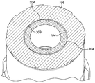
도 3 은 도 2 의 드릴 비트 샤프트 의 앤빌 단부 및 풋 밸브를 절단한 측단면도이고;
도 4 는 도 3 의 풋 밸브의 외부 사시도이고;
도 5 는 도 2 의 드릴 비트의 앤빌 단부의 외부 사시도이고;
도 6 는 도 3 의 A-A 를 따라 절단한 단면도이고;
도 7 은 풋 밸브가 회전 잠금전 드릴 비트 샤프트 통로 내에서 제자리에 있는 도 3 의 B-B 를 따라 절단한 부분 단면도이고;
도 8 은 잠금 해제 위치에서 풋 밸브와 드릴 비트 샤프트의 통로 사이의 잠금 및 인접 영역에서 도 7 의 대응하는 축방향 단면도이고;
도 9 는 풋 밸브가 드릴 비트 샤프트 통로 내에서 축방향 잠금 위치로 회전되는 도 3 의 B-B 를 따라 절단한 부분 단면도이고;
도 10 은 잠금 위치에서 풋 밸브와 드릴 비트 샤프트의 통로 사이의 잠금 및 인접 영역에서 도 9 의 대응하는 축방향 단면도이다.BRIEF DESCRIPTION OF THE DRAWINGS FIG. 1 is an axial cross-sectional view of a downwardly-reshaped hammer drill assembly in accordance with certain embodiments of certain inventions;
Figure 2 is an external perspective view of the drill bit end of the assembly of Figure 1;
Figure 3 is a side cross-sectional view of the anvil end and foot valve of the drill bit shaft of Figure 2;
Figure 4 is an external perspective view of the foot valve of Figure 3;
Figure 5 is an external perspective view of the anvil end of the drill bit of Figure 2;
FIG. 6 is a cross-sectional view taken along AA of FIG. 3; FIG.
Figure 7 is a partial cross-sectional view of the foot valve cut along BB in Figure 3 in place in the drill bit shaft passage before rotation lock;
Figure 8 is a corresponding axial cross-sectional view of Figure 7 in the lock and adjacent region between the passages of the foot valve and the drill bit shaft in the unlocked position;
Figure 9 is a partial cross-sectional view taken along BB of Figure 3, in which the foot valve is rotated into the axial lock position within the drill bit shaft passage;
Figure 10 is a corresponding axial cross-sectional view of Figure 9 in the lock and adjacent region between the passages of the foot valve and the drill bit shaft in the locked position.
도 1 을 참고하면, 하향 천공식 (DTH) 해머 드릴 조립체 (100) 는 축방향 후방 단부 (101a) 및 축방향 전방 단부 (101b) 를 구비한 실질적으로 중공의 원통형 케이싱 (101) 을 포함한다. 상단 서브 (102) 는 케이싱 (101) 의 후방 단부 (101a) 내에 적어도 부분적으로 수용되고 드릴 비트 (105) 는 케이싱 전방 단부 (101b) 내에 적어도 부분적으로 수용된다. 드릴 비트 (105) 는 내부 통로 (116) 를 구비한 세장형 샤프트 (106) 를 포함한다. 드릴 비트 헤드 (107) 는 샤프트 (106) 의 전방 단부에 제공되고, 그리고 복수의 내마모성 절삭 버튼들 (108) 을 포함한다. 샤프트 (106) 의 축방향 후방면 (117) 은 드릴 비트 (105) 의 앤빌 단부를 나타낸다. Referring to FIG. 1, a downward threaded (DTH)
분배기 실린더 (121) 는 축방향으로 연장된 내부 캐비티를 규정하는 내향의 실질적으로 원통형 케이싱 표면 (112) 과 접촉하도록 케이싱 (101) 내에 축방향으로 연장된다. 세장형의 실질적으로 원통형 피스톤 (103) 은 실린더 (121) 및 케이싱 (101) 내에서 축방향으로 연장되고, 그리고 조립체 (100) 를 통하여 연장되는 중심의 종방향 축 (109) 을 따라 전후로 셔틀링할 수 있다. 피스톤 (103) 은 축방향 후방 단부 (114) 및 축방향 전방 단부 (115) 를 포함한다. 내부 보어 (113) 는 축방향 후방 단부 (114) 와 축방향 전방 단부 (115) 사이에서 축방향으로 연장된다. The
풋 밸브 (104) 는 드릴 비트 샤프트 (106) 의 앤빌 단부로부터 축방향 후방으로 돌출하고, 그리고 후방 단부 (119) 및 전방 단부 (110) 를 구비한 일반적인 원통형 구성을 포함한다. 외부 통로 (118) 는 드릴 비트 통로 (116) 및 피스톤 통로 (113) 와 유체 연통하면서 단부들 (119, 110) 사이에서 축방향으로 연장된다. 특히, 풋 밸브 (104) 의 축방향 전방 영역은 드릴 비트 샤프트 (106) 의 후방 앤빌 단부 영역 내에 내장되어 축방향으로 잠금된다. 특히, 풋 밸브 (104) 의 축방향 길이의 절반 조금 더 되는 길이는 앤빌 단부 (117) 로부터 후방으로 연장된다.The
케이싱 (101) 및 분배기 실린더 (121) 는 축방향 후방 영역 (111a) 및 축방향 전방 영역 (111b) 을 구비한 내부 챔버를 규정한다. 피스톤 (103) 은 챔버 영역들 (111a, 111b) 내에서 셔틀하도록 축방향으로 왕복 운동할 수 있다. 특히, 가압 유체는 상단 서브 (102) 에 커플링된 드릴 스트링 (미도시) 을 통하여 드릴 조립체 (100) 에 전달된다. 분배기 실린더 (121) 및 상단 서브 (102) 는 챔버 영역들 (111a, 111b) 에 대한 유체의 공급을 제어한다. 특히 및 인식되는 바와 같이, 축방향 후방 영역 (111a) 으로 유체가 공급되면, 피스톤 (103) 은 드릴 비트 (105) 를 향하여 축방향으로 강제되어 피스톤 전방 단부 (115) 가 앤빌 단부 (117) 를 가격하여 절삭 버튼들 (108) 에 타격식 드릴링 작용을 제공한다. 그런 다음에 유체는 전방 캐비티 영역 (111b) 으로 공급되어 상단 서브 (102) 를 향하여 축방향 후방으로 피스톤 (103) 을 강제한다. 피스톤 (103) 이 축방향 최전방 위치에 있으면, 풋 밸브 (104) 는 피스톤 통로 (113) 내에 정합되어 드릴 비트 통로 (116) 와 캐비티 영역 (111b) 사이의 유체 연통을 격리시키고 폐쇄한다. 피스톤 (103) 이 축방향 후방으로 변위되면서, 피스톤 단부 (115) 는 풋 밸브 단부 (119) 와 떨어져 가압 유체가 드릴 비트 통로 (116) 내에서 유동하게 하고, 그리고 플러싱 채널들 (120) 을 통하여 드릴 비트 헤드 (107) 로부터 배출되게 한다. 따라서, 캐비티 영역들 (111a, 111b) 에 대한 유체의 분배된 공급은 피스톤 (103) 의 급속 및 왕복식 셔틀링 작용을 발생시켜, 결과적으로, 풋 밸브 (104) 와의 반복적인 정합 접촉으로 인하여, 타격식 드릴링 작용의 일부로서 드릴 비트 헤드 (107) 에서 가압 유체의 맥동 배출을 제공한다. The
도 2 및 도 3 을 참고하면, 풋 밸브 (104) 는 축방향 후방 길이 섹션 (306) 및 축방향 전방 길이 섹션 (305) 을 포함하고, 섹션 (305) 은 섹션 (306) 보다 더 큰 외부 직경으로 구성되도록 고려될 수도 있다. 반경방향으로 돌출한 환형 칼라 (303) 는 섹션들 (306, 305) 사이의 접합부에 축방향으로 위치된다. 통로 (118) 는 후방 단부 (119) 와 전방 단부 (110) 사이에서 연장되는 실질적으로 원통형의 내향 표면 (301) 에 의해서 규정된다. 후방 길이 섹션 (306) 은 드릴 비트 샤프트 앤빌 단부 (117) 로부터 축방향 후방으로 돌출되어 반경방향 외향 밸브 표면 (300) 은 노출되고, 그리고 피스톤 통로 (113) 의 최전방 단부에 대하여, 그리고 이 단부 내에서 슬라이딩 접촉할 수 있다. 대응하는 반경방향 외향 밸브 표면 (309) 은 샤프트 통로 (116) 를 규정하는 드릴 비트 샤프트 (106) 의 반경방향 내향 표면 (307) 과 반대로 위치되도록 구성된다. 특히, 통로 (116) 의 축방향 후방 영역 (302) 은 더 큰 외부 직경 길이 섹션 (305) 을 수용하도록 반경방향으로 확장된다. 밸브 (104) 가 샤프트 (106) 의 앤빌 단부에서 제자리에 잠금될 때, 축방향 최전방 밸브 단부 (110) 는 통로 영역 (302) 의 축방향 최전방 단부 (308) 에 매우 근접하게 축방향으로 공존한다. 밸브 통로 (118) 의 내부 직경은 섹션 (306) 에 대한 섹션 (305) 의 더 큰 외부 직경이 이 섹션 (305) 에서 더 큰 밸브 벽 두께에 의해서 제공되도록 단부들 (119, 110) 사이에서 실질적으로 균일하다. 이런 구성은 밸브 (104) 와 드릴 비트 샤프트 (106) 사이의 마찰 끼워 맞춤 배열을 제공하고 또한 샤프트 (106) 로부터 밸브 (104) 의 초기 커플링, 실가동 (operational use) 및 디커플링 동안 밸브 (104) 에서 응력들 및 응력 집중들을 견디는 이점을 제공한다. 2 and 3, the
전방 길이 섹션 (305) 에서, 그리고 이 섹션을 중심으로 (축 (109) 에 대하여) 원주방향으로 분포된 복수의 반경방향으로 이격된 러그들 (304) 에 의해서 부분적으로 드릴 샤프트 (106) 에서 밸브 (104) 의 마찰 끼워 맞춤 및 축방향 잠금이 또한 제공된다. 도 4 를 참고하면, 각각의 러그 (304) 는 칼라 (303) 와 최전방 단부 (110) 사이에서 축방향으로 반경방향 외향 표면 (309) 에서 별개의 상승된 험프로서 형성된다. 각각의 러그 (304) 는 일반적으로 직사각형 형상 프로파일로 구성되고, 그리고 축방향 후방면 (402), 축방향 전방면 (401) 및 한쌍의 길이방향 측면들 (403) 에 의해서 규정되고, 이들 면들은 일반적으로 직사각형 형상 프로파일로 또한 구성되는 공통 플래토면 (400) 에서 이들 면들의 반경방향 최외단부들이 전체적으로 종결된다. 전방면 (401), 후방면 (402) 및 측면들 (403) 은 각각의 러그 (304) 가 완만하게 상승된 럼프로서 형성되도록 테이퍼진다.The radially spaced
도 4 를 참고하면, 각각의 러그 (304) 의 원주방향 길이 (A) 는 대응하는 축방향 길이 (B) 보다 작다. 특히, 밸브 (104) 는 표면 (309) 을 중심으로 원주방향으로 동일하게 이격된 3개의 러그들 (304) 을 포함하여 러그들 (304) 간의 원주방향 이격 거리는 러그 원주방향 길이 (A) 및 축방향 길이 (B) 보다 크다. 4, the circumferential length A of each
도 5 를 참고하면, 복수의 반경방향으로 연장된 숄더들 (502) 은 축방향 후방 통로 영역 (302) 의 내향 표면 (307) 을 중심으로 원주방향으로 분포된다. 각각의 숄더 (502) 는 표면 (307) 으로부터 반경방향 내부로 돌출하고, 그리고 중간 채널들 (501) 에 의해서 이웃하는 숄더들 (502) 로부터 원주방향으로 동일하게 이격된다. 각각의 채널 (501) 은 축방향으로 연장되고, 그리고 앤빌 단부 (117) 와 거의 동축방향으로 위치된 축방향 후방 단부 (504) 및 영역 단부 (308) 에서 거의 공존하는 축방향 전방 단부 (505) 를 포함한다. 각각의 숄더 (502) 의 원주방향 단부들 (503) 은 각각의 채널 (501) 이 숄더들 (502) 사이에서 완만한 곡선 형상 프로파일로 구성되도록 반경방향으로 테이퍼진다. 특정 실시형태에 따르면, 드릴 샤프트 (106) 는 3개의 원주방향으로 이격된 숄더들 (502) 및 채널들 (501) 을 포함한다. 각각의 숄더 (502) 는 축방향 후방 표면 (507) 및 축방향 전방 표면 (506) 에 의해서 축방향으로 규정된다. 각각의 표면 (506, 507) 은 채널들 (501) 사이에서 원주방향으로 연장되고, 그리고 각각의 숄더 (502) 의 반경방향 두께가 위아래로부터 축방향으로 점진적으로 증가되도록 반경방향으로 테이퍼진다. 5, a plurality of radially extending
원주방향 숄더 단부들 (503) 사이의 각각의 채널 (501) 의 원주방향 길이 (C) 는 각각의 러그 (304) 가 인접한 숄더들 (502) 사이에서 축방향으로 통과하게, 그리고 드릴 샤프트 (106) 에서 풋 밸브 (104) 의 초기 커플링 및 이어지는 디커플링 동안 각 채널 (501) 내에서 축방향으로 슬라이딩되게 하도록 러그 원주방향 길이 (A) 보다 약간 더 크다. The circumferential length C of each
또한, 영역 (302) 의 축방향 전방 부분 (509) 은 일반적으로 원추형이 되도록 반경방향으로 테이퍼지고, 그리고 밸브 (104) 의 테이퍼진 일반적으로 원추형의 단부 영역 (310) 과 정합하도록 구성된다. The axial
도 6 는 도 3 의 A-A 를 따라 절단한 단면도를 예시한다. 도시된 바와 같이, 각각의 러그 (304) 는 칼라 (303) 와 최전방 단부 (110) 사이의 밸브 길이 섹션 (305) 의 반경방향 최외부를 나타낸다. 따라서, 각각의 러그 (304) 는 통로 (116) 의 반경방향 내향 표면 (309) 과 긴밀하게 접촉하도록 위치된다. 섹션 A-A 는 밸브 (104) 가 드릴 비트 (105) 에서 잠금 위치에 있으면서 축방향으로 각각의 숄더 (502) 를 지나서 (또는 그 아래로) 축방향 영역 (508) 에 대응한다. 이 위치에서, 각각의 러그 (304) 는 후방 영역 (302) 에서 통로 (116) 의 최내부 영역을 나타내는 대응하는 숄더 (502) 를 반경방향으로 겹치게 위치된다. Fig. 6 illustrates a cross-sectional view taken along line A-A of Fig. 3; As shown, each
드릴 샤프트 (106) 에서 밸브 (104) 의 축방향 커플링 및 디커플링은 도 7 및 도 8 을 참고로 하여 예시되고 설명된다. 각각의 러그 (304) 가 각 채널 (501) 과 원주방향으로 정렬되면, 밸브 (104) 는 드릴 샤프트 (106) 에서 축방향으로 변위될 수도 있다. 샤프트 (106) 에서 밸브 (104) 의 축방향 잠금은 도 9 및 도 10 을 참고로 하여 예시되고 설명된다. 특히, 밸브 (104) 는 숄더들 (502) 및 채널들 (501) 에 대하여 원주방향으로 러그들 (304) 을 변위시키도록 축 (109) 을 중심으로 회전된다. 특히, 각각의 러그 후방면 (402) 은 숄더면 (506) 과 접촉하여 회전되어 통로 (116) 내에서 밸브 (104) 의 마찰 끼워 맞춤을 제공할 수 있다. 각각의 러그 (304) 및 각각의 숄더 (502) 의 반경방향 돌출로 인하여, 러그들 (304) 및 숄더들 (502) 은 도 10 에 예시된 바와 같이 반경방향으로 겹쳐져 밸브 (104) 가 드릴 샤프트 (106) 로부터 축방향으로 빠지는 것을 방지한다. 특히, 축방향 운동은 3쌍의 각 표면들 (402, 506) 간의 인접 접촉들에 의해서 방지된다. The axial coupling and decoupling of the
본 발명의 구성은 수동으로 밸브 (104) 를 통로 (116) 내로 간단히 압축함으로써 드릴 샤프트 (106) 에서 밸브 (104) 의 초기 커플링을 허용하는 이점이 있다. 밸브 (104) 는 그때 숄더들 (502) 의 축방향 단부 표면들 (506) 과 접촉하게 러그들 (304) 과 맞물리도록 축 (109) 을 중심으로 간편한 회전을 통하여 축방향으로 잠금 또는 잠금해제될 수도 있다. 본 발명의 조립체는 특정 스웨깅 장치 (기계식, 유압식 또는 공압식 프레스들) 에 대한 필요성 없이 편리하게 커플링 및 디커플링될 수도 있고, 그리고 수동으로 및/또는 공통 표준 공구들을 사용하여 작업자에 의해서 현장에서 조작될 수도 있다.The configuration of the present invention has the advantage of allowing initial coupling of the
Claims (14)
전방 절삭 단부 (107) 및 후방 앤빌 단부 (117) 를 구비한 드릴 비트 (105) 로서, 상기 후방 앤빌 단부 (117) 로부터 상기 전방 절삭 단부 (107) 를 향하여 상기 해머 드릴 비트 조립체 (100) 의 종방향 축 (109) 을 따라 내부 통로 (116) 가 연장되는, 상기 드릴 비트 (105);
상기 후방 앤빌 단부 (117) 로부터 축방향으로 연장되도록 상기 내부 통로 (116) 내에서 부분적으로 착좌된 풋 밸브 (104);
상기 내부 통로 (116) 의 반경방향 내향 표면 (307) 과 상기 풋 밸브 (104) 의 반경방향 외향 표면 (309) 에 각각 제공된 상보적인 인접 영역들 (304, 502) 로서, 각각의 상기 상보적인 인접 영역들 (304, 502) 은 서로 인접하고 상기 풋 밸브 (104) 를 상기 드릴 비트 (105) 에 축방향으로 잠금하도록 구성된, 상기 상보적인 인접 영역들 (304, 502) 을 포함하고;
상기 상보적인 인접 영역들 (304, 502) 은
상기 종방향 축 (109) 을 중심으로 원주방향으로 이격된 복수의 반경방향으로 돌출한 러그들 (304); 및
상기 종방향 축 (109) 을 중심으로 원주방향으로 이격된 복수의 반경방향으로 돌출한 숄더들 (502) 을 포함하고;
상기 숄더들 (502) 사이의 원주방향 이격 거리 (C) 는 상기 풋 밸브 (104) 를 반경방향으로 실질적으로 변형시키지 않으면서 상기 러그들 (304) 이 상기 숄더들 (502) 사이에서 축방향으로 통과하도록 상기 러그들 (304) 의 원주방향 길이 (A) 와 적어도 동일하거나 이 원주방향 길이 (A) 보다 크고;
각각의 러그 (304) 의 축방향 후방 단부는 인접 접촉 표면 (402) 을 제공하도록 반경방향으로 테이퍼지고, 그리고 각각의 숄더 (502) 의 축방향 전방 단부는 인접 접촉 표면 (506) 을 제공하도록 반경방향으로 테이퍼지고;
상기 숄더들 (502) 및 상기 러그들 (304) 의 반경방향 길이는 상기 러그들 (304) 이 축방향으로 상기 숄더들 (502) 을 지나서 위치되면, 상기 러그들 (304) 및 상기 숄더들 (502) 의 상기 인접 접촉 표면들 (402, 506) 이 함께 정합되어 상기 내부 통로 (116) 내에서 반경방향으로 겹쳐지고, 그리고 상기 드릴 비트 (105) 에서 상기 풋 밸브 (104) 의 독립적인 회전을 축방향으로 잠금하고 억제하는 마찰 끼워 맞춤 영역들을 제공하도록 구성되는 것을 특징으로 하는, 하향 천공식 해머 드릴 비트 조립체. A down-the-hole hammer drill bit assembly 100,
A drill bit (105) having a front cutting end (107) and a rear anvil end (117), wherein the bit of the hammer drill bit assembly (100) from the rear anvil end (117) toward the front cutting end The drill bit (105), the internal passageway (116) extending along a directional axis (109);
A foot valve (104) partially seated within said internal passageway (116) to extend axially from said rear anvil end (117);
Wherein complementary adjacent regions (304, 502) provided on a radially inwardly facing surface (307) of the inner passage (116) and a radially outwardly facing surface (309) of the foot valve (104) The regions 304 and 502 are adjacent to each other and are configured to axially lock the foot valve 104 to the drill bit 105, including the complementary adjacent regions 304 and 502;
The complementary adjacent regions 304,
A plurality of radially projecting lugs (304) circumferentially spaced about said longitudinal axis (109); And
A plurality of radially projecting shoulders (502) circumferentially spaced about said longitudinal axis (109);
The circumferential spacing distance C between the shoulders 502 is such that the lugs 304 are axially spaced between the shoulders 502 without substantially deforming the foot valve 104 radially. Is greater than or equal to the circumferential length (A) of the lugs (304) to pass therethrough;
The axially rearward end of each lug 304 tapers radially to provide an adjacent contact surface 402 and the axial forward end of each shoulder 502 is tapered to provide an adjacent contact surface 402, Tapering in direction;
The radial lengths of the shoulders 502 and the lugs 304 are such that when the lugs 304 are positioned axially past the shoulders 502 the lugs 304 and the shoulders & The adjacent contact surfaces 402 and 506 of the footplate 104 are matched together radially within the internal passageway 116 and the independent rotation of the foot valve 104 at the drill bit 105 Wherein the fastening member is configured to provide friction fit areas that axially lock and restrain the fastening of the drill bit.
3개의 러그들 (304) 및 3개의 숄더들 (502) 을 포함하는, 하향 천공식 해머 드릴 비트 조립체.The method according to claim 1,
Comprising three lugs (304) and three shoulders (502).
각각의 러그 (304) 는 별개의 상승된 범프로서 형성되는, 하향 천공식 해머 드릴 비트 조립체.3. The method according to claim 1 or 2,
Wherein each lug (304) is formed as a separate raised bump.
각각의 러그 (304) 의 상기 인접 접촉 표면 (402) 은 상향 경사진 접촉 표면 (402) 을 제공하도록 반경방향으로 테이퍼지고, 그리고 각각의 숄더 (502) 의 상기 인접 접촉 표면 (506) 은 하향 경사진 접촉 표면 (506) 을 제공하도록 반경방향으로 테이퍼져 상기 상향 경사진 표면 (402) 과 상기 하향 경사진 표면 (506) 은 겹쳐진 접촉을 통하여 함께 정합하도록 상보적인, 하향 천공식 해머 드릴 비트 조립체.4. The method according to any one of claims 1 to 3,
The adjacent contact surface 402 of each lug 304 is radially tapered to provide an upwardly sloping contact surface 402 and the adjacent contact surface 506 of each shoulder 502 is tapered downwardly Wherein the upwardly inclined surface (402) and the downwardly sloping surface (506) are tapered radially to provide a photographic contact surface (506) complementary to each other through overlapping contacts.
각각의 러그 (304) 및 각각의 숄더 (502) 는 각각의 러그 (304) 및 각각의 숄더 (502) 가 상기 풋 밸브 (104) 의 상기 반경방향 외향 표면 (309) 및 상기 내부 통로 (116) 의 상기 반경방향 내향 표면 (307) 각각과 완만한 전이부에 의해서 형성되도록 반경방향으로 테이퍼진 한쌍의 각각의 길이방향 측 표면들 (403, 503) 에 의해서 부분적으로 규정되는, 하향 천공식 해머 드릴 비트 조립체.5. The method of claim 4,
Each lug 304 and each shoulder 502 is configured such that each lug 304 and each shoulder 502 is spaced from the radially outward surface 309 and the inner passage 116 of the foot valve 104, Defined by a pair of respective longitudinal side surfaces 403, 503 tapered radially so as to be defined by each of the radially inwardly directed surfaces 307 of the tapered, Bit assembly.
상기 러그들 (304) 및 상기 숄더들 (502) 은 상기 전방 절삭 단부 (107) 에 대하여 상기 후방 앤빌 단부 (117) 에 축방향으로 가장 근접하게 위치되는, 하향 천공식 해머 드릴 비트 조립체.6. The method of claim 5,
Wherein said lugs (304) and said shoulders (502) are located axially closest to said rear anvil end (117) with respect to said forward cutting end (107).
상기 내부 통로 (116) 및/또는 상기 풋 밸브 (104) 의 표면 (307, 402) 의 영역 (506, 508) 은 상기 드릴 비트 (105) 에서 상기 풋 밸브 (104) 의 회전시 상기 드릴 비트 (105) 에서 상기 풋 밸브 (104) 를 마찰 끼워 맞춤하도록 원주방향으로 반경방향으로 테이퍼지는, 하향 천공식 해머 드릴 비트 조립체.7. The method according to any one of claims 1 to 6,
The areas 506 and 508 of the inner passageway 116 and / or the surfaces 307 and 402 of the foot valve 104 allow the drill bit 105 to rotate in the direction of rotation of the foot valve 104, 105) radially tapering circumferentially to friction fit the foot valve (104).
상기 풋 밸브 (104) 는 플라스틱 재료로 구성되고, 그리고 상기 드릴 비트 (105) 는 금속 또는 금속 합금 재료로 구성되는, 하향 천공식 해머 드릴 비트 조립체.8. The method according to any one of claims 1 to 7,
Wherein the foot valve (104) is comprised of a plastic material and the drill bit (105) is comprised of a metal or metal alloy material.
상기 러그들 (304) 은 상기 풋 밸브 (104) 의 상기 반경방향 외향 표면 (309) 으로부터 반경방향 외부로 돌출하고, 그리고 상기 숄더들 (502) 은 상기 내부 통로 (116) 의 상기 반경방향 내향 표면 (307) 으로부터 반경방향 내부로 연장되는, 하향 천공식 해머 드릴 비트 조립체. 9. The method according to any one of claims 1 to 8,
The lugs 304 project radially outward from the radially outwardly facing surface 309 of the foot valve 104 and the shoulders 502 protrude radially outwardly from the radially outwardly facing surface 309 of the inner passage 116. [ (307) radially inwardly.
상기 내부 통로 (116) 내에 위치되도록 구성된 상기 풋 밸브 (104) 의 길이방향 영역 (305) 내에서, 상기 러그들 (304) 은 상기 풋 밸브 (104) 의 반경방향 최외부를 나타내고; 그리고
상기 풋 밸브 (104) 에 대향하여 정합되도록 구성된 상기 드릴 비트 (105) 의 길이방향 영역 (302) 내에서, 상기 숄더들 (502) 은 상기 내부 통로 (116) 의 반경방향 최내부를 나타내는, 하향 천공식 해머 드릴 비트 조립체.10. The method of claim 9,
Within the longitudinal region 305 of the foot valve 104 configured to be positioned within the internal passageway 116, the lugs 304 represent the radially outermost portion of the foot valve 104; And
Within the longitudinal region 302 of the drill bit 105 configured to mate against the foot valve 104, the shoulders 502 define a radially innermost interior portion of the internal passageway 116, Clamped Hammer Drill Bit Assembly.
상기 숄더들 (502) 은 상기 후방 앤빌 단부 (117) 에 위치된 상기 내부 통로 (116) 의 개구 (500) 의 반경방향 위치에 대하여 반경방향 내부로 위치되는, 하향 천공식 해머 드릴 비트 조립체.11. The method of claim 10,
Wherein said shoulders (502) are located radially inward relative to a radial position of an opening (500) of said inner passage (116) located at said rear anvil end (117).
상기 풋 밸브 (104) 는 제 1 길이 섹션 (306) 및 제 2 길이 섹션 (305) 을 포함하고, 상기 제 2 길이 섹션 (305) 은 상기 제 1 길이 섹션 (306) 에 대하여 더 큰 외부 직경을 갖고, 상기 러그들 (304) 은 상기 제 2 길이 섹션 (305) 내에 위치되는, 하향 천공식 해머 드릴 비트 조립체.12. The method of claim 11,
The foot valve 104 includes a first length section 306 and a second length section 305 and the second length section 305 has a larger outer diameter relative to the first length section 306 And wherein the lugs (304) are located within the second length section (305).
상기 제 2 길이 섹션 (305) 을 지나서 반경방향 외부로 연장되고, 그리고 상기 제 1 길이 섹션 (306) 과 상기 제 2 길이 섹션 (305) 사이의 접합부에서 축방향으로 위치된 환형 칼라 (303) 를 추가로 포함하는, 하향 천공식 해머 드릴 비트 조립체.13. The method of claim 12,
An annular collar 303 extending radially outward beyond the second length section 305 and axially positioned at the junction between the first length section 306 and the second length section 305, Further comprising: a downwardly-deformed, shaped hammer drill bit assembly.
Applications Claiming Priority (3)
| Application Number | Priority Date | Filing Date | Title |
|---|---|---|---|
| EP13193303.8A EP2873799B1 (en) | 2013-11-18 | 2013-11-18 | Down-the-hole hammer drill bit assembly |
| EP13193303.8 | 2013-11-18 | ||
| PCT/EP2014/074125 WO2015071203A2 (en) | 2013-11-18 | 2014-11-10 | Down-the-hole hammer drill bit assembly |
Publications (1)
| Publication Number | Publication Date |
|---|---|
| KR20160086355A true KR20160086355A (en) | 2016-07-19 |
Family
ID=49626822
Family Applications (1)
| Application Number | Title | Priority Date | Filing Date |
|---|---|---|---|
| KR1020167014922A Withdrawn KR20160086355A (en) | 2013-11-18 | 2014-11-10 | Down-the-hole hammer drill bit assembly |
Country Status (9)
| Country | Link |
|---|---|
| US (1) | US9534444B2 (en) |
| EP (1) | EP2873799B1 (en) |
| KR (1) | KR20160086355A (en) |
| CN (1) | CN105829632B (en) |
| AU (1) | AU2014350345B2 (en) |
| CA (1) | CA2929983A1 (en) |
| MX (1) | MX2016006421A (en) |
| RU (1) | RU2668889C1 (en) |
| WO (1) | WO2015071203A2 (en) |
Families Citing this family (8)
| Publication number | Priority date | Publication date | Assignee | Title |
|---|---|---|---|---|
| CA2972829C (en) | 2015-03-27 | 2022-03-08 | Anderson, Charles Abernethy | Apparatus and method for modifying axial force |
| WO2020051637A1 (en) * | 2018-09-10 | 2020-03-19 | Ignis Technologies Pty Ltd | A bit and a bit drive and retention system for a downhole hammer and associated shroud and porting system |
| JP2022510850A (en) * | 2018-11-22 | 2022-01-28 | ミンコン インターナショナル リミテッド | Drill bit assembly for percussion drilling equipment |
| US11680452B2 (en) | 2019-06-12 | 2023-06-20 | Caterpillar Global Mining Equipment Llc | System and method for disassembling drill assemblies |
| MX2022004362A (en) * | 2019-10-11 | 2022-07-27 | Sandvik Mining And Construction Tools Ab | SHOULDER PROTECTED DRILLING ASSEMBLY. |
| FI130902B1 (en) * | 2020-07-03 | 2024-05-21 | Robit Plc | DRILL ASSEMBLY FOR PERCUSSION DRILLING |
| US12392202B2 (en) * | 2023-10-11 | 2025-08-19 | Center Rock Inc. | Down-the-hole drill hammer having a ribbed exhaust tube |
| CN120506191B (en) * | 2025-07-22 | 2025-10-03 | 浙江普兰卡钎具股份有限公司 | A down-the-hole drill bit expansion structure |
Family Cites Families (15)
| Publication number | Priority date | Publication date | Assignee | Title |
|---|---|---|---|---|
| US4278135A (en) | 1978-05-03 | 1981-07-14 | Reedrill, Inc. | Variable volume pneumatic drill |
| ZA795944B (en) * | 1978-11-10 | 1980-11-26 | Halifax Tool Co Ltd | Connection of rod-like components |
| SU1682548A1 (en) * | 1989-10-16 | 1991-10-07 | Старооскольский Механический Завод | Air-percussion drilling device |
| AUPN357995A0 (en) * | 1995-06-15 | 1995-07-06 | Rear, Ian Graeme | Down hole hammer assembly |
| SE520358C2 (en) | 1998-03-03 | 2003-07-01 | Sandvik Ab | Striking lowering hammer and drill bit |
| DE69914770T2 (en) | 1998-08-20 | 2005-05-12 | The Johns Hopkins University School Of Medicine | MITOCHONDRIALE, TUMORMARKER SUITABLE MUTATIONS ONLY BASED ON A BASE PAIR |
| JP4901059B2 (en) * | 2000-09-22 | 2012-03-21 | アトラス・コプコ・セコロツク・エル・エル・シー | Quick release drill bit for downhole drills |
| CA2606202C (en) * | 2005-04-27 | 2013-09-24 | Atlas Copco Secoroc Ab | Exhaust valve and bit assembly for down-hole percussive drills |
| US20080099218A1 (en) | 2006-10-26 | 2008-05-01 | Sandvik Intellectual Property Ab | Air actuated down-the-hole hammer for rock drilling, a drill bit and a foot valve to be used in the down-the-hole hammer |
| RU75420U1 (en) * | 2008-04-28 | 2008-08-10 | Открытое акционерное общество "Кыштымское машиностроительное объединение" | SUBMERSIBLE SHOULDER HAMMER (OPTIONS) |
| SE533590C2 (en) * | 2009-01-14 | 2010-11-02 | Wassara Ab | Drill bit for submersible drill |
| US7992652B2 (en) * | 2009-02-05 | 2011-08-09 | Atlas Copco Secoroc Llc | Fluid distributor cylinder for percussive drills |
| AU2010280347A1 (en) * | 2009-08-05 | 2012-03-22 | Bernard Lionel Gien | Bit assembly for a down-the-hole hammer drill |
| US8561730B2 (en) | 2010-03-23 | 2013-10-22 | Atlas Copco Secoroc Llc | Foot valve assembly for a down hole drill |
| EP2612981B1 (en) | 2012-01-09 | 2014-07-16 | Sandvik Intellectual Property AB | A drill bit for a percussive hammer, and shank and retention lug therefore |
-
2013
- 2013-11-18 EP EP13193303.8A patent/EP2873799B1/en not_active Not-in-force
-
2014
- 2014-11-10 MX MX2016006421A patent/MX2016006421A/en unknown
- 2014-11-10 CA CA2929983A patent/CA2929983A1/en not_active Abandoned
- 2014-11-10 RU RU2016124114A patent/RU2668889C1/en not_active IP Right Cessation
- 2014-11-10 WO PCT/EP2014/074125 patent/WO2015071203A2/en not_active Ceased
- 2014-11-10 US US15/037,092 patent/US9534444B2/en not_active Expired - Fee Related
- 2014-11-10 KR KR1020167014922A patent/KR20160086355A/en not_active Withdrawn
- 2014-11-10 CN CN201480063094.5A patent/CN105829632B/en not_active Expired - Fee Related
- 2014-11-10 AU AU2014350345A patent/AU2014350345B2/en not_active Ceased
Also Published As
| Publication number | Publication date |
|---|---|
| AU2014350345B2 (en) | 2018-05-10 |
| WO2015071203A2 (en) | 2015-05-21 |
| EP2873799B1 (en) | 2017-06-14 |
| CN105829632A (en) | 2016-08-03 |
| AU2014350345A1 (en) | 2016-05-26 |
| EP2873799A1 (en) | 2015-05-20 |
| US20160298390A1 (en) | 2016-10-13 |
| CN105829632B (en) | 2019-05-10 |
| WO2015071203A3 (en) | 2015-10-29 |
| US9534444B2 (en) | 2017-01-03 |
| RU2668889C1 (en) | 2018-10-04 |
| RU2016124114A (en) | 2017-12-25 |
| MX2016006421A (en) | 2016-07-19 |
| CA2929983A1 (en) | 2015-05-21 |
Similar Documents
| Publication | Publication Date | Title |
|---|---|---|
| KR20160086355A (en) | Down-the-hole hammer drill bit assembly | |
| KR102338147B1 (en) | Quick release down-the-hole hammer drill bit assembly | |
| KR101824509B1 (en) | A down-the-hole hammer | |
| US11578550B2 (en) | Downhole device delivery and associated drive transfer system and method of delivering a device down a hole | |
| RU2718705C2 (en) | Arranging drill bit assembly with submersible striker | |
| KR20090082182A (en) | Air operated downhole hammers and foot valves for drill bits and hammers | |
| US6886645B2 (en) | Liquid seal for wet roof bit | |
| CA2563447C (en) | Improvements in or relating to rock drilling equipment | |
| RU2444605C1 (en) | Well reamer | |
| US12065907B2 (en) | Drill assembly for percussive drilling |
Legal Events
| Date | Code | Title | Description |
|---|---|---|---|
| PA0105 | International application |
Patent event date: 20160603 Patent event code: PA01051R01D Comment text: International Patent Application |
|
| PG1501 | Laying open of application | ||
| PA0201 | Request for examination |
Patent event code: PA02012R01D Patent event date: 20191008 Comment text: Request for Examination of Application |
|
| PC1202 | Submission of document of withdrawal before decision of registration |
Comment text: [Withdrawal of Procedure relating to Patent, etc.] Withdrawal (Abandonment) Patent event code: PC12021R01D Patent event date: 20200227 |
|
| WITB | Written withdrawal of application |