KR20160077144A - Lamps for enhanced optical brightening and color preference - Google Patents
Lamps for enhanced optical brightening and color preference Download PDFInfo
- Publication number
- KR20160077144A KR20160077144A KR1020167013895A KR20167013895A KR20160077144A KR 20160077144 A KR20160077144 A KR 20160077144A KR 1020167013895 A KR1020167013895 A KR 1020167013895A KR 20167013895 A KR20167013895 A KR 20167013895A KR 20160077144 A KR20160077144 A KR 20160077144A
- Authority
- KR
- South Korea
- Prior art keywords
- light
- light source
- violet
- color
- lpi
- Prior art date
Links
Images


Classifications
-
- H05B33/0857—
-
- F21K9/137—
-
- F—MECHANICAL ENGINEERING; LIGHTING; HEATING; WEAPONS; BLASTING
- F21—LIGHTING
- F21K—NON-ELECTRIC LIGHT SOURCES USING LUMINESCENCE; LIGHT SOURCES USING ELECTROCHEMILUMINESCENCE; LIGHT SOURCES USING CHARGES OF COMBUSTIBLE MATERIAL; LIGHT SOURCES USING SEMICONDUCTOR DEVICES AS LIGHT-GENERATING ELEMENTS; LIGHT SOURCES NOT OTHERWISE PROVIDED FOR
- F21K9/00—Light sources using semiconductor devices as light-generating elements, e.g. using light-emitting diodes [LED] or lasers
- F21K9/20—Light sources comprising attachment means
- F21K9/23—Retrofit light sources for lighting devices with a single fitting for each light source, e.g. for substitution of incandescent lamps with bayonet or threaded fittings
- F21K9/233—Retrofit light sources for lighting devices with a single fitting for each light source, e.g. for substitution of incandescent lamps with bayonet or threaded fittings specially adapted for generating a spot light distribution, e.g. for substitution of reflector lamps
-
- F21K9/56—
-
- F—MECHANICAL ENGINEERING; LIGHTING; HEATING; WEAPONS; BLASTING
- F21—LIGHTING
- F21K—NON-ELECTRIC LIGHT SOURCES USING LUMINESCENCE; LIGHT SOURCES USING ELECTROCHEMILUMINESCENCE; LIGHT SOURCES USING CHARGES OF COMBUSTIBLE MATERIAL; LIGHT SOURCES USING SEMICONDUCTOR DEVICES AS LIGHT-GENERATING ELEMENTS; LIGHT SOURCES NOT OTHERWISE PROVIDED FOR
- F21K9/00—Light sources using semiconductor devices as light-generating elements, e.g. using light-emitting diodes [LED] or lasers
- F21K9/60—Optical arrangements integrated in the light source, e.g. for improving the colour rendering index or the light extraction
- F21K9/64—Optical arrangements integrated in the light source, e.g. for improving the colour rendering index or the light extraction using wavelength conversion means distinct or spaced from the light-generating element, e.g. a remote phosphor layer
-
- F—MECHANICAL ENGINEERING; LIGHTING; HEATING; WEAPONS; BLASTING
- F21—LIGHTING
- F21S—NON-PORTABLE LIGHTING DEVICES; SYSTEMS THEREOF; VEHICLE LIGHTING DEVICES SPECIALLY ADAPTED FOR VEHICLE EXTERIORS
- F21S2/00—Systems of lighting devices, not provided for in main groups F21S4/00 - F21S10/00 or F21S19/00, e.g. of modular construction
- F21S2/005—Systems of lighting devices, not provided for in main groups F21S4/00 - F21S10/00 or F21S19/00, e.g. of modular construction of modular construction
-
- F—MECHANICAL ENGINEERING; LIGHTING; HEATING; WEAPONS; BLASTING
- F21—LIGHTING
- F21V—FUNCTIONAL FEATURES OR DETAILS OF LIGHTING DEVICES OR SYSTEMS THEREOF; STRUCTURAL COMBINATIONS OF LIGHTING DEVICES WITH OTHER ARTICLES, NOT OTHERWISE PROVIDED FOR
- F21V19/00—Fastening of light sources or lamp holders
- F21V19/001—Fastening of light sources or lamp holders the light sources being semiconductors devices, e.g. LEDs
- F21V19/0015—Fastening arrangements intended to retain light sources
-
- F—MECHANICAL ENGINEERING; LIGHTING; HEATING; WEAPONS; BLASTING
- F21—LIGHTING
- F21V—FUNCTIONAL FEATURES OR DETAILS OF LIGHTING DEVICES OR SYSTEMS THEREOF; STRUCTURAL COMBINATIONS OF LIGHTING DEVICES WITH OTHER ARTICLES, NOT OTHERWISE PROVIDED FOR
- F21V29/00—Protecting lighting devices from thermal damage; Cooling or heating arrangements specially adapted for lighting devices or systems
- F21V29/50—Cooling arrangements
- F21V29/70—Cooling arrangements characterised by passive heat-dissipating elements, e.g. heat-sinks
-
- F—MECHANICAL ENGINEERING; LIGHTING; HEATING; WEAPONS; BLASTING
- F21—LIGHTING
- F21V—FUNCTIONAL FEATURES OR DETAILS OF LIGHTING DEVICES OR SYSTEMS THEREOF; STRUCTURAL COMBINATIONS OF LIGHTING DEVICES WITH OTHER ARTICLES, NOT OTHERWISE PROVIDED FOR
- F21V9/00—Elements for modifying spectral properties, polarisation or intensity of the light emitted, e.g. filters
- F21V9/08—Elements for modifying spectral properties, polarisation or intensity of the light emitted, e.g. filters for producing coloured light, e.g. monochromatic; for reducing intensity of light
-
- G—PHYSICS
- G02—OPTICS
- G02B—OPTICAL ELEMENTS, SYSTEMS OR APPARATUS
- G02B5/00—Optical elements other than lenses
- G02B5/20—Filters
- G02B5/206—Filters comprising particles embedded in a solid matrix
-
- H—ELECTRICITY
- H05—ELECTRIC TECHNIQUES NOT OTHERWISE PROVIDED FOR
- H05B—ELECTRIC HEATING; ELECTRIC LIGHT SOURCES NOT OTHERWISE PROVIDED FOR; CIRCUIT ARRANGEMENTS FOR ELECTRIC LIGHT SOURCES, IN GENERAL
- H05B45/00—Circuit arrangements for operating light-emitting diodes [LED]
- H05B45/20—Controlling the colour of the light
-
- F—MECHANICAL ENGINEERING; LIGHTING; HEATING; WEAPONS; BLASTING
- F21—LIGHTING
- F21Y—INDEXING SCHEME ASSOCIATED WITH SUBCLASSES F21K, F21L, F21S and F21V, RELATING TO THE FORM OR THE KIND OF THE LIGHT SOURCES OR OF THE COLOUR OF THE LIGHT EMITTED
- F21Y2101/00—Point-like light sources
-
- F21Y2101/02—
-
- F—MECHANICAL ENGINEERING; LIGHTING; HEATING; WEAPONS; BLASTING
- F21—LIGHTING
- F21Y—INDEXING SCHEME ASSOCIATED WITH SUBCLASSES F21K, F21L, F21S and F21V, RELATING TO THE FORM OR THE KIND OF THE LIGHT SOURCES OR OF THE COLOUR OF THE LIGHT EMITTED
- F21Y2115/00—Light-generating elements of semiconductor light sources
- F21Y2115/10—Light-emitting diodes [LED]
Landscapes
- Engineering & Computer Science (AREA)
- General Engineering & Computer Science (AREA)
- Physics & Mathematics (AREA)
- Optics & Photonics (AREA)
- Microelectronics & Electronic Packaging (AREA)
- Spectroscopy & Molecular Physics (AREA)
- General Physics & Mathematics (AREA)
- Non-Portable Lighting Devices Or Systems Thereof (AREA)
- Led Device Packages (AREA)
- Electroluminescent Light Sources (AREA)
- Luminescent Compositions (AREA)
Abstract
한 실시형태에서, 본 개시는 적어도 하나의 고체 상태 광 에미터를 포함하는 광원을 제공한다. 광원은, 동작에서, 적어도 약 105의 조명 선호도 지수(LPI)를 갖는 실질적으로 화이트의 광을 방출하고, 광원으로부터의 이 방출은 적어도 약 1%의 UV-바이올렛 플럭스를 포함한다. 본 개시의 램프, 광원, 및 방법의 사용은, 에너지 효율적인 LED 기반 조명 하에서 리넨 및 의류를 디스플레이할 능력을 제공할 수도 있고, (특히 화이트의) 의류에 대해, 종래 기술의 LED 램프에 의한 조명 하에서 보다 더 깨끗하게 보이게 만드는 효과를 부여할 수도 있다.In one embodiment, the present disclosure provides a light source comprising at least one solid state optical emitter. The light source, in operation, emits substantially white light with an illumination preference index (LPI) of at least about 105, and this emission from the light source comprises at least about 1% UV-violet flux. The use of lamps, light sources, and methods of the present disclosure may provide the ability to display linen and garments under energy-efficient LED-based illumination, and may be used for garments (especially white), under illumination by prior art LED lamps It may also give you the effect of making it look cleaner.
Description
관련 출원에 대한 교차 참조Cross-reference to related application
본 출원은, 선출원인 2014년 9월 9일자로 출원된 함께 계류 중인 공동 소유의 국제 출원 PCT/US2014/054868의 일부 계속 출원이다. 본 출원은 또한, 35 USC 119(e)하에서, 2013년 10월 28일자로 출원된 공동 소유의 가출원 61/896445로부터의 이점을 주장한다. 이들 출원은 그들 전체가 본원에서 개시되는 것처럼 참조에 의해 본원에 통합된다.This application is a continuation-in-part of co-pending, co-pending international application PCT / US2014 / 054868, filed September 9, 2014, This application also claims benefit under 35 USC 119 (e) from co-owned provisional application 61/896445, filed October 28, These applications are hereby incorporated by reference in their entirety as if fully set forth herein.
분야Field
본 발명은 조명 기술에 관한 것으로, 특히, LED 기반 램프 및 광원(light source)에 관한 것이다.FIELD OF THE INVENTION The present invention relates to lighting technology, and more particularly to LED based lamps and light sources.
일반적인 조명을 위한 램프 및 광원은 많은 형태를 취할 수도 있다. 소매 설정(retail setting)에서 사용되는 조명에 대해(뿐만 아니라, 주거, 환대, 병원, 교육, 박물관, 및 상업적 조명 등등을 위해), 높은 연색성 지수(color rendering index; CRI)를 갖는 램프 또는 광원이 역사적으로 소망되고 있다. 역사적으로, 백열(incandescent) 및 할로겐 램프가 이러한 설정에 대한 소망의 특성을 제공하기 위해 사용되는 통상적인 타입의 광원이었다. 높은 연색성(color rendering) 외에, 또는 높은 연색성 대신, 몇몇 광원은 높은 컬러 선호도를 제공할 수도 있는데, 이에 의해, 몇몇 또는 대부분의 컬러는 기준 발광원(reference illuminant)과 비교하여 현시(appearance)를 향상하였다(예를 들면, REVEAL® 브랜드 하의 GE의 향상된 컬러 제품). 램프 및 광원은 또한 애플리케이션의 소망의 빔 분포 속성을 만족하는 지향성 조명을 제공할 수도 있다. 이들 역사적 광원은 보통은 빠른 웜업 및 응답 시간, 높은 광 강도 출력을 가지며, 양호한 연색성 또는 컬러 선호도 특성을 가지지만, 불량한 효능 및 상대적으로 짧은 램프 수명이 문제가 될 수도 있다. 보다 최근에 개발된 고강도 방전(high intensity discharge; HID) 램프, 특히 세라믹 메탈 할라이드(ceramic metal halide; CMH) 램프는, 높은 CRI, 높은 컬러 선호도, 및 더 높은 빔 강도와 함께, 역사적인 램프 타입보다 훨씬 더 높은 효능을 제공할 수도 있지만, 불충분한 램프 수명, 수명에 걸친 그리고 램프마다의 불량한 컬러 제어, 및 보다 높은 비용이 문제가 될 수 있다.Lamps and light sources for general lighting may take many forms. Lamps or light sources with a high color rendering index (CRI) for lighting used in retail settings (as well as for residential, hospitality, hospitals, education, museums, and commercial lighting etc.) It is historically desired. Historically, incandescent and halogen lamps were a common type of light source used to provide the desired characteristics for this setting. In addition to high color rendering, or instead of high color rendering, some light sources may provide high color preference, whereby some or most of the colors may have improved appearance compared to a reference illuminant (For example, GE's enhanced color products under the REVEAL® brand). The lamp and light source may also provide directional illumination that satisfies the desired beam distribution properties of the application. These historical light sources usually have fast warm-up and response times, high light intensity output, good color rendering or color preference characteristics, but poor efficacy and relatively short lamp life may be a problem. More recently developed high intensity discharge (HID) lamps, especially ceramic metal halide (CMH) lamps, have been developed with a high CRI, high color preference, and higher beam intensity, While it may provide higher efficacy, insufficient lamp life, poor color control per lamp over the life span, and higher cost can be a problem.
이들 기존의 기술이 일반적으로 허용가능한 성능을 제공하지만, 성능, 및/또는 컬러 품질에서의 추가적인 향상, 및/또는 제조 단가에서의 감소, 및/또는 증가된 콘센트(wall plug) 에너지 효율성, 및/또는 증가된 램프 수명 및 신뢰성이 바람직할 것이다.While these existing techniques generally provide acceptable performance, additional improvements in performance, and / or color quality, and / or reduced manufacturing costs, and / or increased wall plug energy efficiency and / Or increased lamp life and reliability.
최근, 고체 상태 광(solid state light; SSL) 에미터(예를 들면, 발광 다이오드 또는 LED; 레이저 다이오드 또는 LD; 및 유기 발광 다이오드 또는 OLED)에 기초한 광원이 중심이 되고 있는데, 전력을 광으로 변환함에 있어서의 이들의 아주 높은 효율성, 백열 및 할로겐 램프와 비교했을 때의 긴 수명, 스펙트럼 재단(tailoring), 소형 사이즈 및 고휘도를 가능하게 하는 다양하게 이용가능한 컬러, 및 빠르게 줄어들고 있는 비용 덕택이다. 본 발명은 SSL 광원에 의해 가능하게 되는 스펙트럼 재단 기회 덕택의 화이트 및 컬러 오브젝트를 조명하는 새로운 성능과 주로 관련된다.In recent years, light sources based on solid state light (SSL) emitters (for example, light emitting diodes or LEDs; laser diodes or LDs and organic light emitting diodes or OLEDs) Their high efficiency in terms of brightness, long lifetime compared to incandescent and halogen lamps, spectral tailoring, the variety of colors available to enable compact size and high brightness, and the rapidly decreasing cost. The present invention primarily relates to new capabilities for illuminating white and color objects due to spectral cutting opportunities made possible by SSL light sources.
많은 공지의 LED 칩(종종 다이로 칭해짐)은, 갈륨 질화물, 아연 산화물, 실리콘 탄화물, 또는 이들의 조합과 같은 그러나 이들로 제한되지는 않는 반도체 재료를 포함하는 적어도 하나의 반도체 층을 포함할 수도 있다. 예를 들면, 많은 공지의 LED 칩은, 식 IniGajAlkN(여기서 0<i; 0<j; 0<k 및 i+j+k=1)으로 표현되는 것과 같은 In, Ga, Al 및 N의 질화물 화합물 반도체를 포함할 수도 있다.Many well known LED chips (often referred to as dies) may include at least one semiconductor layer comprising a semiconductor material such as, but not limited to, gallium nitride, zinc oxide, silicon carbide, or combinations thereof have. For example, in many known are LED chip, formula In i Ga j Al k N (where 0 <i; 0 <j; 0 <k and i + j + k = 1), as represented by In, Ga, Al and N nitride compound semiconductors.
많은 공지의 LED 기반 광원은, 일반적인 조명 애플리케이션 및 많은 특수한 애플리케이션 예컨대 소매 세팅에서 사용하기 위해, 실질적으로 화이트로 보이는 광을 생성하도록 구성되었다. 많은 공지의 LED 기반 광원은, 특히 연색성 지수(CRI) 및 소정의 레드 컬러의 오브젝트(예를 들면, R9)의 렌더링과 관련하여, 우수한 연색성 속성을 달성하기 위한 광의 재단된 스펙트럼 파워 분포를 갖는다.Many known LED-based light sources are configured to produce light that appears substantially white for use in general lighting applications and many specialized applications, such as retail settings. Many known LED-based light sources have a tailored spectral power distribution of light to achieve good color rendering properties, particularly with respect to rendering of a color rendering index (CRI) and a predetermined red color object (e.g., R 9 ) .
특히, 화이트 및 컬러의 오브젝트의 혼합물을 구비하는 화이트 및 밝은 컬러의 의복 또는 소매 상품 세팅과 관련하여, 의류, 및 소매 상품 세팅과 같은 소매 상품 아이템을 조명하는 데 사용하기 위한 화이트 LED 램프를 지속적으로 향상시키려는 일반적인 소망이 존재한다. 물론, 이러한 광원은 또한, 소매 상품 이외의 애플리케이션, 예컨대 예를 들면, 주거, 환대, 교육, 박물관, 병원, 상점, 만찬, 상업용, 및 다른 컬러 민감 애플리케이션에서 선호되는 발광원일 수도 있다.In particular, with respect to white and light colored clothing or retail merchandise settings comprising a mixture of white and colored objects, a white LED lamp for use in illuminating items of retail commodity such as clothing, and retail merchandise settings, There is a general desire to improve. Of course, such a light source may also be a preferred light source in applications other than retail merchandise, such as in residential, hospitality, education, museum, hospital, shop, dinner, commercial, and other color sensitive applications.
한 실시형태에서, 본 개시는 적어도 하나의 고체 상태 광 에미터를 포함하는 광원을 제공한다. 광원은, 동작에서, 적어도 약 105의 조명 선호도 지수(Lighting Preference Index; LPI)를 갖는 실질적으로 화이트의 광을 방출하고, 광원으로부터의 이 방출은 적어도 약 1%의 UV-바이올렛 플럭스(UV-violet flux)를 포함한다.In one embodiment, the present disclosure provides a light source comprising at least one solid state optical emitter. The light source, in operation, emits substantially white light with an illumination preference index (LPI) of at least about 105, and the emission from the light source is at least about 1% UV-violet flux flux.
다른 실시형태에서, 본 개시는, 적어도 하나의 고체 상태 화이트 광 에미터; 적어도 하나의 고체 상태 화이트 광 에미터로부터 옐로우 광을 선택적으로 흡수하도록 구성되는 옐로우 흡수 컬러 필터; 및 적어도 하나의 고체 상태 UV-바이올렛 에미터를 포함하는 광원을 제공한다.In another embodiment, the disclosure provides a light emitting device comprising: at least one solid state white light emitter; A yellow absorbing color filter configured to selectively absorb yellow light from at least one solid state white light emitter; And at least one solid-state UV-violet emitter.
다른 실시형태에서, 본 개시는 적어도 하나의 고체 상태 광 에미터를 포함하는 광원을 제공한다. 광원은, 동작시, 형광 오브젝트의 현시적 휘도(apparent brightness)를 향상시키거나 또는 향상시킬 수 있고, 또한, 적어도 약 105의 조명 선호도 지수(LPI)를 갖는 실질적으로 화이트의 광을 방출한다.In another embodiment, the disclosure provides a light source comprising at least one solid state optical emitter. The light source, in operation, can improve or improve the apparent brightness of the fluorescent object and also emits substantially white light with an illumination preference index (LPI) of at least about 105.
또 다른 실시형태에서, 본 개시는, 적어도 하나의 고체 상태 광 에미터를 포함하는 광원을 이용하여 형광 오브젝트(fluorescent object)를 조명하는 것을 포함하는 방법을 제공한다. 광원은, 동작에서, 적어도 약 105의 조명 선호도 지수(LPI)를 갖는 실질적으로 화이트의 광을 방출하고, 적어도 약 1%의 UV-바이올렛 플럭스를 포함한다.In yet another embodiment, the present disclosure provides a method comprising illuminating a fluorescent object with a light source comprising at least one solid state optical emitter. The light source, in operation, emits substantially white light with an illumination preference index (LPI) of at least about 105, and comprises at least about 1% UV-Violet flux.
또 다른 실시형태에서, 본 개시는 반사성 또는 굴절성 빔 성형 광학장치(beam-forming optic)를 포함하는 지향성 램프; 빔 성형 광학장치와 광학적으로 연통하는 광 엔진; 및 광 엔진으로부터의 복사 플럭스를 컬러 필터링하기 위한 옐로우 흡수 컬러 필터를 제공한다. 광 엔진은 UV-바이올렛 LED 칩 및 블루 LED 칩의 어레이를 포함한다. 어레이는, 그 발광면의 적어도 일부 상에서, 형광체 조성물(phosphor composition)로 코팅된다. 형광체 조성물은 적어도 하나의 옐로우 또는 옐로우-그린 형광체, 및 적어도 하나의 레드 형광체를 포함한다. 광 엔진은 적어도 약 1%의 UV-바이올렛 플럭스를 방출하고, 이 UV-바이올렛 플럭스는 지향성 램프에 의해 방출되는 것이 바람직하다. 지향성 램프는, 동작에서, 적어도 약 105의 조명 선호도 지수(LPI)를 갖는 실질적으로 화이트의 광을 방출한다.In another embodiment, the disclosure provides a directional lamp comprising a reflective or refractive beam-shaping optic; A light engine in optical communication with the beam shaping optics; And a yellow absorbing color filter for color filtering radiation flux from the light engine. The light engine includes an array of UV-violet LED chips and blue LED chips. The array is coated with a phosphor composition on at least a portion of its light emitting surface. The phosphor composition comprises at least one yellow or yellow-green phosphor, and at least one red phosphor. The light engine emits at least about 1% of the UV-violet flux, which is preferably emitted by the directional lamp. The directional lamp, in operation, emits substantially white light having an illumination preference index (LPI) of at least about 105.
본 발명의 양태 및/또는 특징 및 이들의 부수적인 이익 및/또는 이점 중 많은 것은, 첨부의 도면과 연계하여 취해지는 상세한 설명을 참조하는 것에 의해 보다 쉽게 명확해지고 이해될 것인데, 도면은 일정 축척이 아닐 수도 있으며, 도면에서:
도 1은, 통상적인 형광 오브젝트의 방출 스펙트럼을, UV-바이올렛 여기(excitation)의 다양한 파장의 함수로서 묘사한다.
도 2는, 형광 방출 강도의 피크가 나타내어지는 경우에서의 도 1과 동일한 데이터 대 형광 오브젝트의 형광(fluorescence)을 여기시키고 있는 UV-바이올렛 LED의 파장을 묘사한다.
도 3은 세 개의 등색 함수(color matching function) 대 사람 망막에 대한 광의 파장을 디스플레이한다.
도 4는 약 2700 K의 공칭 CCT를 갖는 여러 개의 실질적으로 화이트의 광원의 컬러 포인트를 포함하는 색도 공간(ccx, ccy)의 플롯을 제공한다.
도 5a 및 도 5b는 추가적인 UV-바이올렛 플럭스가 없는, 그리고 추가적인 UV-바이올렛 플럭스를 갖는 컬러 포인트에 대한 비교 스펙트럼 파워 분포를 도시한다.
도 6은 다양한 컬러 온도에 대한 흑체 곡선 및 "백체 라인(white-body line)"의 위치를 묘사한다.
도 7a는 먼셀(Munsell) 시스템의 색상(hue)의 10 개의 카테고리를 묘사한다.
도 7b는 주어진 CRV(color rendition vector; 연색 벡터)에 포함되는 여러 성분을 예시한다.
도 7c는 주어진 조건 하에서의 네오디뮴 백열 램프에 대한 많은 연색 벡터를 나타낸다.
도 8a는 종래 기술의 LED 제품에 대한 스펙트럼 파워 분포 곡선이다.
도 8b는 다른 종래 기술의 LED 제품에 대한 스펙트럼 파워 분포 곡선이다.
도 9a 내지 도 9d는 본 발명의 실시형태에 따른 어레이의 개략적인 뷰를 개시한다.
도 10a 내지 도 10f는 본 발명의 실시형태에 따른 CoB 어레이에서의 블루 LED 칩 및 UV-바이올렛 칩의 예시적인 레이아웃을 묘사한다.
도 11은, 본 발명의 실시형태에 따른, 약 406 nm에서 피크 파장을 갖는 36 개의 UV-바이올렛 LED 칩, 및 36 개의 블루 LED 칩을 포함하는 예시적인 형광체 변환 CoB 어레이(phosphor-converted CoB array)로부터 생성되는 SPD를 디스플레이한다.
도 12는 종래 기술의 세라믹 메탈 할라이드(CMH) 램프로부터 생성되는 SPD를 디스플레이한다.
도 13a 및 도 13b는 통상적인 YAG 및 질화물 형광체에 대한 통상적인 여기 및 방출 스펙트럼을 도시한다.BRIEF DESCRIPTION OF THE DRAWINGS Aspects and / or features of the present invention and many of the attendant benefits and / or advantages thereof will be more readily apparent and understood by reference to the detailed description taken in conjunction with the accompanying drawings, , And in the drawings:
Figure 1 depicts the emission spectrum of a typical fluorescent object as a function of various wavelengths of UV-violet excitation.
Fig. 2 depicts the wavelength of the UV-violet LED which excites the fluorescence of the fluorescence object versus the same data as in Fig. 1 when the peak of fluorescence emission intensity is indicated.
Figure 3 displays the wavelengths of light for the three color matching functions versus the human retina.
Figure 4 provides a plot of the chromaticity space (ccx, ccy) that includes the color points of several substantially white light sources with a nominal CCT of about 2700K.
Figures 5A and 5B show a comparison spectral power distribution for color points with no additional UV-violet flux and with additional UV-violet flux.
Figure 6 depicts the blackbody curve and the location of the "white-body line" for various color temperatures.
Figure 7a depicts ten categories of hues in a Munsell system.
FIG. 7B illustrates various components included in a given CRV (color rendition vector).
Figure 7c shows many color rendering vectors for a neodymium incandescent lamp under given conditions.
8A is a spectral power distribution curve for a prior art LED product.
8B is a spectral power distribution curve for another prior art LED product.
9A-9D disclose a schematic view of an array in accordance with an embodiment of the present invention.
10A-10F depict exemplary layouts of a blue LED chip and a UV-violet chip in a CoB array in accordance with an embodiment of the present invention.
Figure 11 shows an exemplary phosphor-converted CoB array comprising 36 UV-violet LED chips having a peak wavelength at about 406 nm and 36 blue LED chips, according to an embodiment of the present invention. Lt; / RTI >
Figure 12 displays SPDs generated from prior art ceramic metal halide (CMH) lamps.
13A and 13B show typical excitation and emission spectra for conventional YAG and nitride phosphors.
본 개시의 실시형태는 적어도 하나의 고체 상태 광 에미터를 포함하는 광원에 관한 것으로, 광원은 동작에서 형광 오브젝트의 현시적 휘도를 향상시킬 수 있고, 광원은 동작에서 향상된 컬러 선호도, 예를 들면 적어도 약 100의 조명 선호도 지수(LPI)를 갖는 실질적으로 화이트의 광을 방출한다. 본원에서, 용어 "LPI"는, 통상적인 관찰자에 의한 그 발광원(광원)의 선호도의 레벨을, 광범위한 화이트 및 컬러의 오브젝트의 그 광원 하에서의 현시에 기초하여 정량화하는 조명 선호도 지수(LPI)에 대한 정량적 식에 의해 정의된다. LPI는 하기에서, 그리고 2014년 9월 9일자로 출원된 공동 소유의 국제 출원 PCT/US2014/054868에서 추가로 설명되는데, 이 출원은 참조에 의해 통합된다.Embodiments of the present disclosure relate to a light source comprising at least one solid state optical emitter wherein the light source can improve the invisible brightness of the fluorescent object in operation and the light source has improved color preference in operation, And emits substantially white light having a lighting preference index (LPI) of about 100. As used herein, the term "LPI" refers to the level of preference of the light source (light source) by a typical observer for a lighting preference index (LPI) that quantifies based on the appearance of a broad white and color object under its light source. It is defined by a quantitative equation. The LPI is further described below and in co-owned international application PCT / US2014 / 054868, filed September 9, 2014, which is incorporated by reference.
본원에서 사용되는 바와 같이, 용어 "광원"은, 시스템 복잡도가 증가하는 순서의 하기의 광의 소스 중 임의의 것을 포함한다.As used herein, the term "light source" includes any of the following sources of light in order of increasing system complexity.
(a) 광원은 고체 상태 광원(SSL) 에미터, 예컨대 LED 칩 또는 LD 칩 또는 발광 트랜지스터(light emitting transistor; LET) 칩, 또는 OLED 패널, 또는 다른 SSL 에미터를 지칭할 수도 있다. SSL 에미터의 정의는 반도체를 기계적으로 지지하기 위한 그리고 반도체에 대한 전기적 접속을 제공하기 위한 반도체 접합 및 수단을 포함할 수도 있다;(a) the light source may refer to a solid state light source (SSL) emitter, such as an LED chip or LD chip or a light emitting transistor (LET) chip, or an OLED panel, or other SSL emitter. The definition of the SSL emitter may include semiconductor junctions and means for mechanically supporting the semiconductor and for providing electrical connection to the semiconductor;
(b) 광원은 광 엔진을 지칭할 수도 있는데, 광 엔진은 통상적으로, SSL 에미터 중 일부 또는 전체로부터의 기여를 포함하는 광의 방출을 제공하는 복수의 SSL 에미터이다;(b) the light source may refer to a light engine, which is typically a plurality of SSL emitters providing emission of light including contributions from some or all of the SSL emitters;
(c) 광원은 조명 모듈(lighting module)을 지칭할 수도 있는데, 조명 모듈은 통상적으로는 지지 구조체 상에 마운팅되는 광 엔진이다. 조명 모듈은 통상적으로, 반도체 접합으로부터 열 관리 시스템으로의 열 경로뿐만 아니라, 전기적 연결을 포함할 수도 있고, 광학 컴포넌트 또는 시스템을 포함할 수도 있다;(c) the light source may refer to a lighting module, which is typically a light engine mounted on a support structure. Lighting modules typically include electrical connections as well as thermal paths from a semiconductor junction to a thermal management system, and may include optical components or systems;
(d) 광원은 램프를 지칭할 수도 있는데, 램프는 통상적으로 조명 모듈, 전자 드라이버, 광학 컴포넌트 또는 시스템, 열 관리 컴포넌트 또는 시스템, 베이스 또는 커넥터, 및 옵션적으로, 제어부를 포함할 수도 있다. 램프는 A19, BR30, PAR38과 같은 폼팩터, 또는 다른 지향성 또는 전방향 폼팩터를 포함할 수도 있다. 대안적으로, 광원은 조명 기구(luminaire)를 지칭할 수도 있는데, 조명 기구는 하나 이상의 램프 또는 램프를 통상적으로 포함하는 컴포넌트, 및 고정구(fixture), 예컨대 트로퍼(troffer)를 포함할 수도 있다;(d) the light source may refer to a lamp, which may typically include an illumination module, an electronic driver, an optical component or system, a thermal management component or system, a base or connector, and, optionally, a control. The lamp may include form factors such as A19, BR30, PAR38, or other directional or omnidirectional form factors. Alternatively, the light source may refer to a luminaire, which may include components that typically include one or more lamps or lamps, and a fixture, such as a troffer;
(e) 광원은 조명 시스템을 포함할 수도 있는데, 조명 시스템은 일반적으로 복수의 램프 또는 조명 기구이며, 이들은 시스템 레벨에서 상호접속되어 제어될 수도 있다.(e) The light source may comprise an illumination system, which is generally a plurality of lamps or luminaire, which may be interconnected and controlled at the system level.
상기 광원 중 임의의 것은, 본 개시의 지침에 따라, 형광 오브젝트의 현시적 휘도를 향상시킬 수 있고 동작에서 향상된 컬러 선호도, 예를 들면, 적어도 약 100의 조명 선호도 지수(LPI)를 갖는 실질적으로 화이트의 광을 방출할 수 있도록 구성되거나 적응될 수도 있다.Any of the light sources may be configured to substantially enhance the temporal brightness of the fluorescent object and to provide improved color preference in operation, for example substantially white, with a lighting preference index (LPI) of at least about 100, Or may be adapted to emit light of a certain wavelength.
본원에서, 용어 "SSL"은 일반적으로, 예를 들면, LED, LD, OLED, 및 발광 트랜지스터(LET 및 OLET)와 같은 다른 SSL 기술 등등과 같은 임의의 반도체 복사원(radiation source)을 지칭한다.As used herein, the term "SSL" generally refers to any semiconductor radiation source, such as, for example, LEDs, LDs, OLEDs, and other SSL technologies, such as light emitting transistors (LET and OLET)
형광 오브젝트의 현시적 휘도의 향상을 제공하도록 광원을 구성하기 위해, 광원은 적어도 하나의 UV-바이올렛 SSL 에미터를 포함할 것이다. 또한, 향상된 컬러 선호도를 갖는 실질적으로 화이트의 광을 광원이 제공하기 위해서, 광원은 또한, 컬러 선호도를 향상시키는 스펙트럼 파워 분포(SPD)를 갖도록 수정된 화이트 광원을 포함할 것이다. 몇몇 실시형태에서, 화이트 광원은 컬러 선호도를 향상시킬 수 있는 것으로 필터링될 것이다(예를 들면, 네오디뮴 유리에 의해 필터링될 것이다). UV-바이올렛 SSL 에미터 및 광원의 SPD의 향상된 컬러 선호도 "부분"(및 광원의 복합 SPD를 생성하는 데 필요한 임의의 필터링)의 조합은, 광원의 상기 다섯 개의 레벨((a) 내지 (e)) 중 임의의 하나에서 수행될 수도 있다.To configure the light source to provide an improvement in the temporal brightness of the fluorescent object, the light source will include at least one UV-violet SSL emitter. Also, in order for the light source to provide substantially white light with enhanced color preferences, the light source will also include a modified white light source to have a spectral power distribution (SPD) that enhances color preference. In some embodiments, the white light source will be filtered (e.g., filtered by neodymium glass) to improve color preference. The combination of the UV-violet SSL emitter and the enhanced color preference "part" of the SPD of the light source (and any filtering required to produce the composite SPD of the light source) ). ≪ / RTI >
예를 들면, 몇몇 실시형태에서, 옐로우 광의 흡수를 제공하는 네오디뮴 화합물을, LED 칩 내에(즉, 에미터 레벨에서); 또는 LED 패키지의 봉지재(encapsulant)의 일부로서, 또는 광 엔진을 둘러싸는 구조체의 일부로서; 또는 램프 또는 조명 기구에서의 확산기(diffuser) 또는 광학장치의 일부로서; 또는 조명 시스템에서의 복수의 램프 또는 조명 기구 중 일부 또는 전체를 엔클로징하는(enclosing) 필터의 일부로서 배치할 수도 있다. 옐로우 광의 흡수는 컬러 선호도를 향상시키는 하나의 모드일 수도 있다.For example, in some embodiments, neodymium compounds that provide absorption of yellow light may be incorporated within the LED chip (i.e., at the emitter level); Or as part of an encapsulant of an LED package, or as part of a structure surrounding a light engine; Or as part of a diffuser or optics in a lamp or luminaire; Or as part of a filter enclosing some or all of a plurality of lamps or luminaire in the illumination system. The absorption of yellow light may be one mode for improving color preference.
몇몇 실시형태에서, 광원의 SPD의 UV-바이올렛 부분을, 예를 들면, 임의의 하나 이상의 하기의 방식으로 제공할 수도 있다: 하나 이상의 UV-바이올렛 LED 에미터는 LED 패키지 내에 배치될 수도 있거나, 또는 칩 온 보드(chip-on-board; CoB) 어레이에 배치될 수도 있거나; 또는 하나 이상의 UV-바이올렛 광 엔진은 복수의 광 엔진 사이에서 배치될 수도 있거나; 또는 하나 이상의 UV-바이올렛 광원은 복수의 광원 사이에 배치될 수도 있거나; 또는 하나 이상의 UV-바이올렛 램프 또는 조명 기구는 조명 시스템에서의 조명 기구용의 복수의 램프 사이에 배치될 수도 있거나; 등등일 수도 있다.In some embodiments, the UV-violet portion of the SPD of the light source may be provided, for example, in any one or more of the following ways: one or more UV-violet LED emitters may be disposed in the LED package, May be disposed in a chip-on-board (CoB) array; Or one or more UV-violet light engines may be disposed between the plurality of light engines; Or one or more UV-violet light sources may be disposed between the plurality of light sources; Or one or more UV-violet lamps or luminaire may be disposed between the plurality of lamps for the luminaire in the illumination system; And so on.
몇몇 실시형태에서, 향상된 컬러 선호도를 수여하는 광원의 SPD의 부분은, 예를 들면 다음에 의해 제공될 수도 있다: LED 패키지 내의 또는 CoB 어레이의 하나 이상의 향상된 컬러 선호도 LED; 또는 복수의 광 엔진 사이에서의 하나 이상의 향상된 컬러 선호도 광 엔진; 복수의 조명 모듈 사이에서의 하나 이상의 향상된 컬러 선호도 조명 모듈; 또는 조명 시스템의 복수의 램프 또는 조명 기구 사이에서의 하나 이상의 향상된 컬러 선호도 램프 또는 조명 기구; 등등.In some embodiments, the portion of the SPD of the light source that provides enhanced color preference may be provided, for example, by: one or more enhanced color preference LEDs in the LED package or in the CoB array; Or one or more enhanced color preference light engines between the plurality of light engines; One or more enhanced color preference lighting modules between a plurality of lighting modules; Or one or more enhanced color preferences lamps or lighting fixtures between a plurality of lamps or luminaire of a lighting system; etc.
제1 양태에서, 본 발명은, 광증백제(optical brightening agent; OBA)를 포함하는 오브젝트를 밝게 하는 능력을 제공하는 광원을 제공한다. 특히, 이 제1 양태에서, 본 발명은 적어도 하나 또는 복수의 고체 상태 광 에미터를 포함하는 광원을 제공한다. 광원은, 동작시, 실질적으로 화이트로 보이는 복사 플럭스를 생성한다. 광원으로부터 복사하는 복사 플럭스의 어떤 비율이 UV-바이올렛 광 파장 범위 안에 있다. 이러한 비율은 OBA를 포함하는 오브젝트를 증백하는 데 유효하도록 선택된다. 본원에서 사용되는 바와 같이, 용어 "증백한다(brighten)" 또는 "증백하는(brightening)"은 일반적으로, 마치 조명 레벨이 더 높았던 것처럼, 또는 마치 오브젝트의 반사율이 더 높았던 것처럼, OBA를 포함하는 오브젝트로 하여금 조명된 오브젝트의 백색도(whiteness) 또는 휘도의 시각적 인식을 향상시키게 하는 광원을 지칭한다. 이것은 통상적으로, OBA가 형광 복사(fluorescence radiation)를 방출하게끔 자극되도록, 광원이 가시광 외에 UV-바이올렛을 방출할 때 가능하다. 형광 복사선이 블루 파장 영역에 있으면, 백색도는 통상적으로 향상될 것이다. 형광 복사선이 다른 컬러 대역에 있으면, 다른 컬러의 생동감(vibrancy)이 향상될 수도 있다. 통상적으로, 이들 효과는, 오브젝트가 그 표면에 형광 안료(fluorescent pigment)를 포함할 때 발생할 수도 있다. 본원에서, 용어 광증백제(OBA)는 화이트에 대해서 뿐만 아니라 컬러의 오브젝트에 대해서도 증백제를 포함하는 것을 의미한다.In a first aspect, the present invention provides a light source that provides the ability to brighten an object including an optical brightening agent (OBA). In particular, in this first aspect, the present invention provides a light source comprising at least one or more solid state optical emitters. The light source, in operation, produces a radiation flux that appears substantially white. Any fraction of the radiation flux that is emitted from the light source is within the UV-violet light wavelength range. These ratios are selected to be effective to enlarge objects including OBA. As used herein, the terms "brighten" or "brightening" generally refer to an object, including OBA, as if the illumination level was higher, Quot; refers to a light source that allows for improved visual perception of brightness or whiteness of an illuminated object. This is typically possible when the light source emits UV-violet in addition to visible light so that the OBA is stimulated to emit fluorescence radiation. If the fluorescent radiation is in the blue wavelength region, whiteness will usually be improved. If the fluorescent radiation is in a different color band, the vibrancy of other colors may be improved. Typically, these effects may occur when an object includes a fluorescent pigment on its surface. As used herein, the term " OBA " means to include a brightener for objects of color as well as to white.
"제1 양태", "제2 양태" 등등에 대한 임의의 언급은 반드시 상호 배타적인 실시형태를 언급하는 것은 아니다는 것을 유의해야 한다. 따라서, 상기에서 설명되는 바와 같이 증백제를 포함하는 오브젝트를 증백하는 능력을 제공하는 광원은 또한, 하기의 다른 양태에서 상세히 설명되는 바와 같이, 다른 면을 특징으로 할 수도 있다.It should be noted that any reference to "the first aspect ", the" second aspect ", etc. are not necessarily referring to mutually exclusive embodiments. Thus, a light source that provides the ability to magnify an object, including the brightener, as described above, may also feature other aspects, as described in detail in other aspects below.
본원에서, 용어 "복사 플럭스"는, 가시 범위 및 UV 범위의 광원에 의해 방출되는 광의 합을 나타내는데, 광원이 약간의 통상적으로 비가시적인 UV 광을 방출할 수도 있기 때문이다. 본원에서, "UV-바이올렛" 광 파장 범위는 약 425 nm보다 작은, 예를 들면, 약 420 nm보다 작은, 예를 들면, 약 410 nm보다 작은 것으로 정의될 수도 있다. 북미 조명 학회(Illumination Engineering Society of North America; IESNA) 조명 핸드북, 1984 참조서(Reference Volume)는, 자외선 광의 가장 긴 범위 UVA를 315 내지 400 nm를 포함하도록, 그리고 가시 범위를 380 내지 770 nm를 포함하도록 정의한다는 것을 유의한다. 당해 분야의 숙련된 자에 의해 이해되는 바와 같이, UV와 가시 파장의 범위에는 중첩이 존재할 수도 있다. 따라서, 본 개시의 목적을 위해, UV 범위는 범위 315 nm 내지 400 nm를 포함하도록 정의될 수도 있고; 가시 범위는 400 nm 내지 770 nm를 포함하도록 정의될 수도 있다. 더 상세히 설명되는 바와 같이, 현존하는 OBA에 대해 효과적인 파장의 범위는 약 380 내지 약 420 nm이고, 이것은, 정의된 바와 같이, UV와 가시 범위의 가교 역할을 한다. "UV-바이올렛" 광 파장 범위는 약 350 nm로부터 약 425 nm까지, 예를 들면, 약 380 nm 내지 약 420 nm, 예를 들면, 약 400 nm 내지 약 410 nm로서 정의될 수도 있다. "UV-바이올렛"에 대해 선택될 파장 범위는, 일반적으로, 선택된 오브젝트에 대한 증백 효과(brightening effect)를 최대화하도록, 동시에 또한 임의의 UV-바이올렛 복사 방출의 임의의 유해한 효과(예를 들면, 재료의 열화, 또는 안전성 문제, 또는 감소된 효율성 등등)를 경감하거나 최소화하도록 선택된다.As used herein, the term "radiation flux " refers to the sum of light emitted by a light source in the visible range and UV range, since the light source may emit some normally invisible UV light. In the present application, the "UV-violet" light wavelength range may be defined as being less than about 425 nm, for example less than about 420 nm, e.g. less than about 410 nm. The Reference Volume, Illumination Engineering Society of North America (IESNA), Reference Volume, 1984, contains the longest range UVA of UV light from 315 to 400 nm and the visible range from 380 to 770 nm . ≪ / RTI > As will be understood by those skilled in the art, there may be overlap in the range of UV and visible wavelengths. Thus, for purposes of this disclosure, the UV range may be defined to include the range 315 nm to 400 nm; The visible range may be defined to include 400 nm to 770 nm. As will be described in more detail, the effective wavelength range for existing OBAs is from about 380 nm to about 420 nm, which, as defined, serves as a bridge between UV and visible range. The "UV-violet" light wavelength range may be defined as from about 350 nm to about 425 nm, for example, from about 380 nm to about 420 nm, for example, from about 400 nm to about 410 nm. The wavelength range to be selected for "UV-violet" will generally be selected so as to maximize the brightening effect on the selected object, as well as any harmful effects of any UV-violet radiation emission Degradation or safety problems, or reduced efficiency, etc.).
본원에서 사용되는 바와 같이, 용어 "실질적으로 화이트의"는, 통상적으로, 약 2000 K 내지 약 10000 K(보다 전형적으로는 약 2700 K로부터 약 6500 K까지)의 범위의 CCT를 특징으로 하며, 도 6의 하한(606) 및 상한(608)에 의해 묘사되는 바와 같이, 흑체 궤적(blackbody locus; BBL), 또는 백체 라인(white-body line; WBL) 중 어느 하나로부터 단지 약 10 스텝 맥아담 타원(MacAdam ellipse)만큼만 편향되는 컬러 포인트를 갖는 발광원 또는 광원을 지칭한다. 이 해석은 본원에서 제공되는 바와 같이 화이트 광의 인식에 관한 원칙에 적용된다. 대안적으로, "실질적으로 화이트의 광"은, 넓은 의미에서, 예를 들면, 쿨 화이트(cool white), 웜 화이트(warm white), 또는 두 화이트의 조합; 등등과 같은 화이트 광의 다수의 변형체를 포함하도록 해석될 수도 있다.As used herein, the term "substantially white" is typically characterized by a CCT in the range of from about 2000 K to about 10000 K (more typically from about 2700 K to about 6500 K) From the blackbody locus (BBL), or the white-body line (WBL), as depicted by the lower and
광원이 OBA를 포함하는 오브젝트를 조명하기 위해 사용되는 경우, 오브젝트는, UV-바이올렛 광 파장 범위의 복사 플럭스가 없는 동일한 광원과 비교하여, 일반적으로 더 밝게 보일 수도 있다.When a light source is used to illuminate an object comprising OBA, the object may generally appear brighter compared to the same light source without radiation flux in the UV-violet light wavelength range.
증백제는 통상적으로, 형광 재료, 광 미백(whitening) 재료, 인광(phosphorescent) 재료, 또는 형광 안료 등등 중 하나 이상으로부터 선택될 수도 있다. 조명 기술에서 숙련된 자에 의해 이해되는 바와 같이, 형광 재료는 통상적으로 상대적으로 더 짧은 파장(예를 들면, UV-바이올렛)에서 여기되고, 흡수된 에너지를 상대적으로 더 긴 파장(예를 들면, 가시)에서 방출한다. 종종 광 증백제(optical brightener), 광 증백제(optical brightening agent), 형광 증백제 또는 형광 미백제(용어는 실질적으로 유의어로서 간주될 수도 있다)로도 칭해지는 광 미백 재료는, 전자기 스펙트럼의 자외선 및 바이올렛 영역의 광을 흡수하는 무색 염료(colorless dye)이며, 가시 스펙트럼의 다른 영역, 예를 들면, 블루 영역을 재방출한다. 이들 재료는 직물 및 종이의 화이트 현시를 향상시켜, 미백 또는 증백 효과를 야기하고, 통상적으로는, 반사되는 블루 광의 전체 양을 증가시키는 것에 의해 재료를 덜 노랗게 보이게 만들기 위해 종종 사용된다. 종종 "야광(glow-in-the-dark)" 또는 "블랙 라이트(black-light)" 안료(용어는 실질적으로 유의어로서 간주될 수도 있다)로도 칭해지는 형광 안료 재료는, 전자기 스펙트럼의 자외선 및 바이올렛 영역의 광을 흡수하는 무색 염료(colorless dye)이며, 가시 스펙트럼의 다른 영역, 예를 들면, 그린, 옐로우, 및 레드 영역을 재방출한다. 이들 재료는 컬러의 종이, 직물 및 페인트의 생동감을 향상시켜, 증백 효과를 야기하고, 통상적으로는, 재료를, 마치 이들이 자체 발광되거나 또는 보통과는 다르게 밝게 채색된 것처럼 보이게 만들기 위해 종종 사용된다.Brightening agents may also be selected from at least one of a fluorescent material, a whitening material, a phosphorescent material, a fluorescent pigment, and the like. As will be appreciated by those skilled in the lighting arts, fluorescent materials are typically excited at relatively shorter wavelengths (e.g., UV-violet) and absorbed energy at relatively longer wavelengths (e.g., Thorns). BACKGROUND OF THE INVENTION Light whitening materials, sometimes referred to as optical brighteners, optical brightening agents, fluorescent whitening agents or fluorescent whitening agents (the term may also be regarded as substantially synonyms), include ultraviolet light of the electromagnetic spectrum and violet Is a colorless dye that absorbs light in the region and re-emits other regions of the visible spectrum, such as the blue region. These materials improve the white appearance of textiles and paper, bring about whitening or whitening effects, and are typically used to make the material look less yellow by increasing the total amount of blue light being reflected. Fluorescent pigment materials, sometimes referred to as "glow-in-the-dark" or "black-light" pigments (the term may be regarded as substantially synonyms), include ultraviolet and violet Is a colorless dye that absorbs light in the region and re-emits other regions of the visible spectrum, e.g., green, yellow, and red regions. These materials enhance the vibrancy of colored paper, textiles and paints, cause bleaching effects, and are typically used to make materials appear as if they are self-emitting or otherwise brightly colored.
몇몇 실시형태에서, 증백제는, 스틸벤(stilbene) 또는 스틸벤 유도체, 쿠마린(coumarin) 또는 쿠마린 유도체, 티오펜(thiophene) 또는 티오펜 유도체, 비스아졸 또는 비스아졸(bisazole) 유도체, 벤즈옥사존(benzoxazone) 또는 벤즈옥사존 유도체, 또는 피라졸린(pyrazoline) 또는 피라졸린 유도체 등등으로부터 선택되는 화학 물질을 포함할 수도 있다. 다른 화학 물질은, 이들이 오브젝트에 광증백성을 부여하는 데 유효하면, 가능하다. 몇몇 실시형태에서, 증백제는, 그것의 형광 여기 파장이 약 350 내지 약 425 nm의 범위 안에 있을 수도 있도록 선택된다. 통상적으로는, 증백제는 약 420 내지 약 700 nm의 파장에서 형광 방출을 가질 수도 있다. 광증백제의 경우, 보통은, 그 피크 형광 방출이 블루 범위, 또는 약 420 내지 480 nm에 있다.In some embodiments, the brightener is selected from the group consisting of stilbene or stilbene derivatives, coumarin or coumarin derivatives, thiophene or thiophen derivatives, bisazole or bisazole derivatives, benzoxazone benzoxazone or benzoxazone derivatives, or pyrazoline or pyrazoline derivatives, and the like. Other chemicals are possible if they are effective in imparting photons to the object. In some embodiments, the brightener is selected so that its fluorescence excitation wavelength may be in the range of from about 350 to about 425 nm. Typically, the brightener may have fluorescence emission at a wavelength of from about 420 to about 700 nm. In the case of an optical brightener, usually the peak fluorescence emission is in the blue range, or about 420 to 480 nm.
많은 실시형태에서, 증백제를 포함하는 오브젝트는, 종이, 포장 재료, 직물, 의류, 페인트, 치아, 머리카락, 또는 벽, 또는 심지어 증백제를 포함하도록 구성되는 조명 기구를 포함할 수도 있다. 머리카락, 피부 및 치아는, 화장품 또는 샴푸와 같은 개인 케어 제품(personal care product)의 애플리케이션을 통해 증백제를 포함하도록 구성될 수도 있다. 때로는 광증백제를 포함할 수도 있는 다른 재료는 플라스틱, 장난감, 직물 등등을 포함할 수도 있다.In many embodiments, the object comprising a brightener may comprise a lighting device configured to include paper, a packaging material, a fabric, a garment, a paint, a tooth, a hair, or a wall, or even a brightener. The hair, skin and teeth may be configured to include a brightener through the application of a personal care product such as a cosmetic or shampoo. Other materials that may sometimes include an optical brightener may include plastics, toys, fabrics, and the like.
도 1의 스펙트럼은 통상적인 화이트 면 타월(cotton towel)의 방출 스펙트럼을 UV-바이올렛 여기의 다양한 파장의 함수로서 묘사한다. 가로좌표 상의 파장은 나노미터 단위이고, 세로좌표 상의 방출 강도는 임의의("임의") 단위이다. 증백 응답을 제공하는 방출된 광의 파장의 범위를 결정하기 위해, 그리고 OBA로부터의 형광 방출의 강도를, 입사 UV-바이올렛 여기 광의 파장의 함수로서 결정하기 위해, 형광체 특성 분광기(phosphor characterization spectrometer)가 사용되었다. 각각의 내포된 곡선은 UV-바이올렛 LED의 상이한 여기 파장을 나타낸다. 방출 스펙트럼의 피크는 약 435 nm이고, 화이트 타월에 대해 시각적으로 인식가능한 "블루-화이트" 향상을 제공하게 된다. 도 2는, 형광 방출 강도의 피크가 나타내어지는 경우에서의 도 1과 동일한 데이터 대 OBA의 형광을 여기시키고 있는 UV-바이올렛 LED의 파장을 묘사한다. 도 2의 곡선으로부터의 주요 결과는, 증백 효과의 여기에 대한 개시(효과가 약 360 nm에서 발생하는 최대 효과의 약 절반을 초과하는 경우)가 UV-바이올렛 LED의 여기 파장에 대해 약 410 nm에서 발생하고, 더 짧은 여기 파장에서 증가하여, 약 360 nm에서 최대 효과에 도달하지만, 그러나 420 nm와 더 긴 여기 파장은 OBA를 갖는 이 특정 오브젝트에 대해 그만큼 효과적이지 않다. 바람직한 여기 파장이 일반적으로 약 410 nm 미만에서 존재하는 광범위한 다른 화이트 직물에서, 시각적 관찰은 유사한 결과를 제공했다.The spectrum of FIG. 1 depicts the emission spectrum of a conventional white cotton towel as a function of the various wavelengths of UV-violet excitation. The wavelength on the abscissa is in nanometers and the emission intensity on the ordinate is any ("random") unit. A phosphor characterization spectrometer is used to determine the range of wavelengths of emitted light providing a broadening response and to determine the intensity of the fluorescence emission from the OBA as a function of the wavelength of the incident UV- . Each nested curve represents a different excitation wavelength of the UV-violet LED. The peak of the emission spectrum is about 435 nm, providing a visually perceptible "blue-white" improvement over the white towel. Fig. 2 depicts the wavelength of the UV-violet LED which excites the fluorescence of OBA versus the same data as in Fig. 1 when the peak of fluorescence emission intensity is indicated. The main result from the curve of Figure 2 is that the initiation of excitation of the broadening effect (when the effect exceeds about half of the maximum effect occurring at about 360 nm) is at about 410 nm for the excitation wavelength of the UV- And increases at shorter excitation wavelengths, reaching a maximum effect at about 360 nm, but 420 nm and longer excitation wavelengths are not as effective for this particular object with OBA. In a wide range of other white fabrics where the preferred excitation wavelength is generally below about 410 nm, visual observations have provided similar results.
본 발명의 몇몇 실시형태에서, UV-바이올렛의 파장 범위 안에 있는 광원의 복사 플럭스의 비율은, 그것이 실질적으로 화이트의 컬러 포인트를 실질적으로 교란하지 않도록 선택된다. 본원에서, "UV-바이올렛 플럭스의 비율" 또는 "UV-바이올렛 범위에서의 복사 플럭스의 비율"은, 식 1에서 주어지는 바와 같이, 실질적으로 화이트의 광원의 UV-바이올렛 광 부분의 파장 통합 플럭스(와트 단위)를, 실질적으로 화이트의 광원의 파장 통합 가시 플럭스(와트 단위)로 나눈 것이 되도록 정의한다:In some embodiments of the present invention, the ratio of the radiation flux of the light source within the wavelength range of UV-violet is selected such that it does not substantially disturb the color point of the white. As used herein, the term " ratio of UV-violet flux "or" ratio of radiant flux in the UV-violet range "means that the wavelength-integrated flux of the UV- Unit) is divided by the wavelength-integrated visual flux (in watts) of the substantially white light source:

여기서 ![]()
![]()
본 개시의 실시형태에서, 광원의 총 복사 플럭스는 UV-바이올렛 범위의 몇몇 광을 포함하지만, UV-바이올렛 범위의 광의 양은, UV-바이올렛 플럭스로부터의 기여를 포함하는 광원의 컬러 포인트가 실질적으로 화이트가 되는 것이 교란될 정도로 그렇게 많지는 않다.In an embodiment of the disclosure, the total radiant flux of the light source comprises some light in the UV-violet range, but the amount of light in the UV-violet range is such that the color point of the light source, including its contribution from the UV- It is not so much that it becomes disturbing to become.
이것은, UV-바이올렛 광이, 충분히 짧은 파장에서 그리고 UV-바이올렛 플럭스의 충분히 낮은 비율로 방출되면, 사람 눈에 의한 컬러의 인식에 실질적으로 기여하지 않기 때문이다. 이것은, 세 개의 등색 함수(![]()
![]()
이 효과를 정량화하기 위해, 도 4는 약 2700 K의 공칭 CCT를 갖는 실질적으로 화이트의 광원의 컬러 포인트(412, 414, 416, 등등)를 포함하는 색도 공간(ccx, ccy)의 플롯(400)을 제공한다. 광원의 CCT가 2500 K인 등온선(402), 및 광원의 CCT가 3000 K인 등온선(404)이 플롯에 포함된다. 곡선(406)은 흑체 궤적(BBL)인데, 흑체 궤적 상의 색도 포인트(410)는 BBL 상의 CCT=2725 K인 컬러 포인트를 나타내며, 그 컬러 포인트는, 본원에서 참조로 통합되는, 참조 표준 ANSI C78.377-2008에서 2700 K 빈(bin)으로서 명목상 칭해지는 미국 표준 협회(American National Standards Institute; ANSI) 컬러 빈의 윤곽을 표시하는 사변형(quadrangle)(408)의 중심 포인트로서 기능한다. 미국 에너지국(Department of Energy; DoE)에 의한 에너지 스타 인증을 받기 위해서는, LED 교체 램프는, 본원에서 참조로 통합되는, 버전 1.1 일체형 LED 램프 시방서의 요건을 충족해야 하는데, 그 요건은, 램프의 색도가 ANSI C78.377-2008에 의해 제공되는 것과 같이 자신의 공칭 CCT에 대응하는 사변형 내에 위치되어야 한다는 요건을 포함한다. 본원에서, 에너지 스타 인증은, 본 발명의 모든 실시형태의 필수적인 목적 또는 목표로서가 아니라, 80의 최소 CRI 요건과 함께, 공칭 CCT에 대응하는 사변형 내에 놓여 있는 컬러 포인트에 의해 정의되는 바와 같은 컬러 품질을 포함하는 LED 광원에 대한 품질의 업계 인식 표준으로서 참조된다. 따라서, 사변형(408)은 공칭 CCT=2700 K에 대한 에너지 스타 등급의 자격을 받는 색도의 범위를 나타낸다. 2700 K와 함께, 실내 애플리케이션에 대해 의도되는 3000 K, 3500 K, 및 4000 K의 다른 공칭 CCT 값; 및 또한 실외, 산업계 또는 다른 애플리케이션에 대해 의도될 더 높은 공칭 CCT 값에 대해 유사한 요건 및 사변형이 이해될 것이다. 색도 포인트(412)는, 2775 K의 CCT를 가지며, BBL(406)로부터 ANSI 사변형(408)의 둘레까지의 거리의 약 삼분의 일에 대응하는 양만큼 BBL 위에 위치되는 통상적인 상업적으로 입수가능한 웜 화이트(warm-white; WW) LED 광원의 것이다. 이 광원이 중심 색도(410)를 가지지는 않지만, 이 광원은 사변형(408) 내에 놓이며, 따라서 공칭 2700 K 광원으로서 자격을 얻는다. 사변형(408) 내의 임의의 색도는 표준에 따른 허용가능한 색도(컬러) 포인트에 있는 것으로 간주된다. ANSI 사변형의 사이즈는, (2700 K 사변형의 경우) 중심 포인트(410)로부터 7 스텝 맥아담 타원(409)의 최대 편차에 근사하도록 선택되었다. 일 스텝 맥아담 타원은, 중심 컬러 포인트로부터의 컬러 공간에서의 편차가 통상적인 관찰자에 의한 검출가능성의 임계치에 있게 되는 중심 포인트를 둘러싸는 컬러 공간에서의 궤적을 나타낸다. 약 2 내지 4 맥아담 타원까지의 편차는 통상적인 관찰자에 의해 겨우 인식가능하고, 따라서 일반적으로 허용가능하지만; 약 5 또는 그 이상의 맥아담 타원의 편차는 쉽게 인식가능하고 따라서 광원의 유저에 의해 허용가능하지 않을 수도 있다.To quantify this effect, FIG. 4 shows a
다시, 주어진 광원으로부터의 컬러 포인트에서의 편차가 얼마나 허용가능한지를 예시하기 위한 목적으로, 도 4의 논의를 계속한다. 예를 들면, 주어진 실질적으로 화이트의 광원의 컬러 포인트(412)가 2700 K 사변형(408) 내에 놓이면, 예를 들면 광원에 대한 UV-바이올렛 플럭스의 추가에 기인하여 약 2 내지 4 맥아담 타원 내에 놓이는 새로운 컬러로 나타나게 되는 그 컬러 포인트로부터의 편차는, 따라서, 컬러 포인트(412)를 갖는 광원의 일반적으로 허용가능한 변형이라고 생각될 수 있다. 따라서, 컬러 포인트(412)에 중심을 두는 2 스텝 타원(430) 및 4 스텝 타원(432)은, 컬러 포인트(412) 더하기 추가적인 UV-바이올렛 플럭스를 갖는 플럭스를 생성하는 광원에 대한 컬러 포인트의 일반적으로 허용가능한 범위를 나타낸다.Again, for the purpose of illustrating how tolerable the deviation in color point from a given light source is, continue the discussion of FIG. For example, if a given substantially
도 5a는 추가적인 UV-바이올렛 플럭스가 없는 컬러 포인트(412)에 대응하는 SPD(500)를 제공한다. 도 5b의 SPD(502)는, 410 nm의 파장에서 5%의 UV-바이올렛 플럭스를 추가 또는 보충한 SPD(500)를 나타낸다. 복합 SPD(502)는, 컬러 포인트(412)를 중심에 두는 2 스텝 맥아담 타원(430)의 아주 약간 밖에 놓이는 도 4의 컬러 포인트(420)를 생성한다. 보충적인 UV-바이올렛이 없는 SPD(500)를 나타내는 컬러 포인트(412)와 410 nm의 파장에서 5%의 UV-바이올렛 플럭스를 갖는 SPD(502)를 나타내는 컬러 포인트(420) 사이의 약 2 스텝 맥아담 타원의 컬러 시프트는 UV-바이올렛 플럭스 때문이다.5A provides an
SPD(500) 더하기 보충적인 UV-바이올렛 플럭스를 포함하는 광원에 대한 컬러 포인트(414, 416, 418, 420, 422, 423, 424, 426, 428)는, 테이블 I에 따라 라벨링되는 UV-바이올렛 파장에 대한 최대치와 % UV-바이올렛 플럭스의 함수로서 도 4에서 플롯된다.The color points 414, 416, 418, 420, 422, 423, 424, 426, 428 for the light source including the
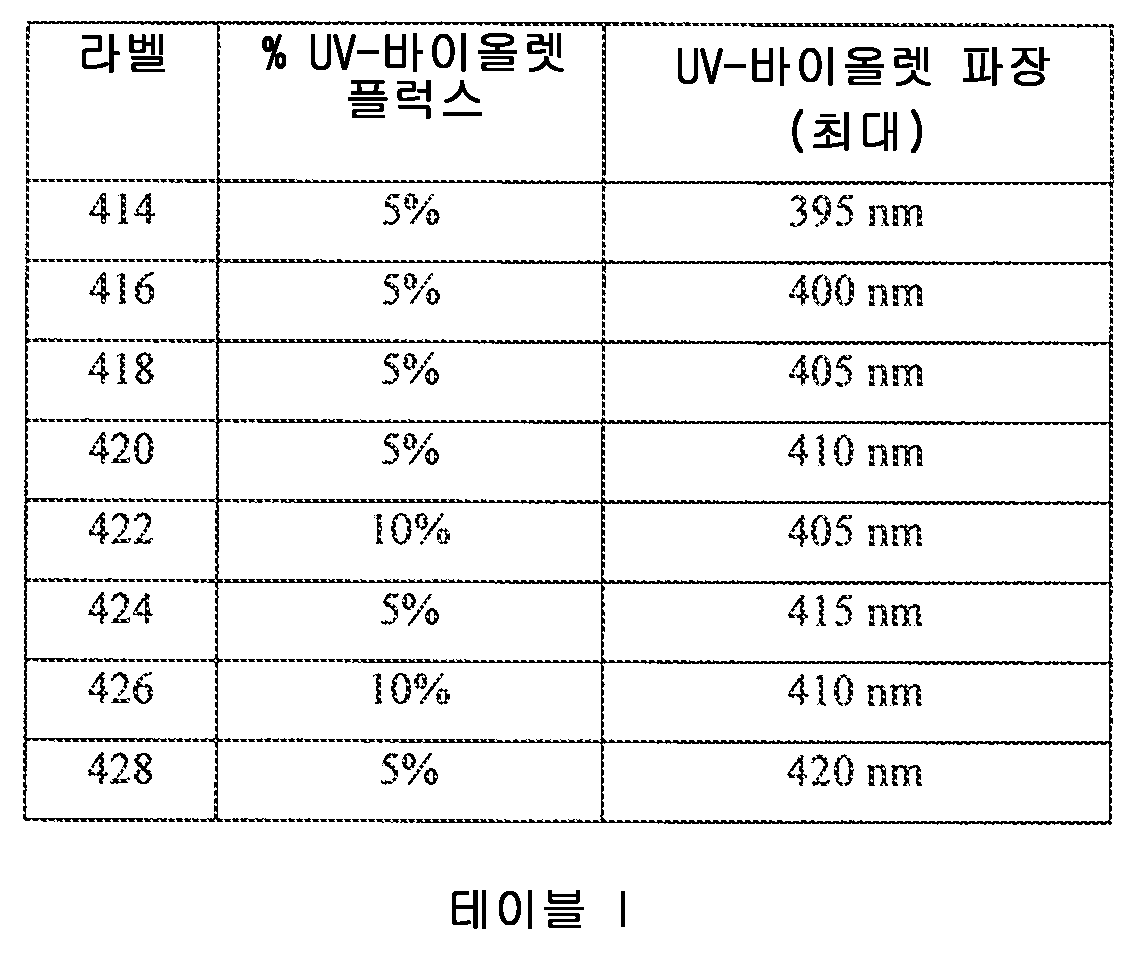
2 스텝 맥아담 타원(430)과의 컬러 포인트(420 및 422)의 비교에 의해 알 수 있는 바와 같이, 410 nm의 파장에서 5% UV-바이올렛 플럭스의 추가, 또는 405 nm의 파장에서 10% UV-바이올렛 플럭스의 추가는 단지 약 2 스텝 맥아담 타원의 컬러 포인트에서의 시프트를 생성하고, 이것은 단지 겨우 인식가능한 컬러 편차를 나타내고, 따라서 컬러 애플리케이션을 구별함에 있어서도 허용가능할 것이다. 실질적으로 5% 미만의 UV-바이올렛 플럭스 및 410 nm 미만의 UV-바이올렛 파장을 갖는 임의의 복합 광원은 2 스텝 맥아담 타원 내에 컬러 포인트를 생성할 것이다. 실질적으로 10% 미만의 UV-바이올렛 플럭스 및 405 nm 미만의 UV-바이올렛 파장을 갖는 임의의 복합 광원은 또한, 2 스텝 맥아담 타원 내에 컬러 포인트를 생성할 것이다.As can be seen by comparison of the color points 420 and 422 with the two
4 스텝 맥아담 타원(432)과의 컬러 포인트(424 및 426)의 비교에 의해 알 수 있는 바와 같이, 415 nm의 파장에서 5% UV-바이올렛 플럭스, 또는 410 nm의 파장에서 10% UV-바이올렛 플럭스는, 단지 약 4 스텝 맥아담 타원의 컬러 포인트에서의 시프트를 생성하고, 이것은 겨우 인식가능한 컬러 편차를 나타내고, 따라서 대부분의 통상적인 애플리케이션에서 허용가능할 것이다. 실질적으로 5% 미만의 UV-바이올렛 플럭스 및 415 nm 미만의 UV-바이올렛 파장을 갖는 임의의 복합 광원은 2 스텝 맥아담 타원 내에 컬러 포인트를 생성할 것이다. 실질적으로 10% 미만의 UV-바이올렛 플럭스 및 410 nm 미만의 UV-바이올렛 파장을 갖는 임의의 복합 광원은 또한, 4 스텝 맥아담 타원 내에 컬러 포인트를 생성할 것이다.5% UV-violet flux at a wavelength of 415 nm, or 10% UV-violet at a wavelength of 410 nm, as can be seen by comparison of the color points 424 and 426 with the four
4 스텝 맥아담 타원(432)과의 컬러 포인트(428)의 비교에 의해 알 수 있는 바와 같이, 420 nm의 파장에서 5% UV-바이올렛 플럭스는, 4 스텝 맥아담 타원을 상당히 초과하는 컬러 포인트에서의 시프트를 생성하고, 이것은 일반적으로 허용불가능한 컬러 편차를 나타내고, 따라서 많은 통상적인 애플리케이션에서 허용가능하지 않을 수도 있다. 실질적으로 5% 미만의 UV-바이올렛 플럭스 및 420 nm 미만의 UV-바이올렛 파장을 갖는 임의의 복합 광원은 4 스텝 맥아담 타원을 상당히 초과하는 컬러 포인트를 생성할 것이고, 일반적으로 허용불가능할 수도 있다.As can be seen by comparison of the
몇몇 다른 실시형태에서, 퍼센트 UV-바이올렛 플럭스와 UV-바이올렛 파장 둘 다는, 복합 광원의 컬러 포인트를 시프트하도록 선택된다. 통상적으로는, 광원의 스펙트럼의 나머지와 결합될 때 CIE 컬러 공간에서의 UV-바이올렛 에미터의 위치가, 백체 궤적(WBL)을 향해, BBL 아래로 시프트되는 복합 컬러 포인트로 나타나기 때문에, 컬러 포인트의 인식된 백색도는, UV-바이올렛 에미터로부터의 상대적으로 강한 기여로 인해 WBL에 더 가깝게 되는 덕택에, 향상된다.In some other embodiments, both the percent UV-violet flux and the UV-violet wavelength are selected to shift the color point of the composite light source. Typically, because the position of the UV-violet emitter in the CIE color space when combined with the rest of the spectrum of the light source appears as a composite color point shifted down the BBL towards the white locus WBL, The perceived whiteness is improved due to being closer to the WBL due to the relatively strong contribution from the UV-violet emitter.
본 개시의 대응하는 제1 방법 양태가 존재하는데, 그 제1 방법 양태는 오브젝트를 더 밝게 만들기 위한 방법에 관련된다. 이 양태에서, 방법은 증백제를 포함하는 오브젝트를 광원으로부터의 광에 노출시키는 단계를 포함하고, 광원은 복수의 고체 상태 에미터를 포함하고 향상된 컬러 선호도(예를 들면, 약 100보다 더 큰 LPI)를 갖는 실질적으로 화이트의 광을 방출한다. 램프로부터의 광이 실질적으로 화이트인 것으로 보이지만, 광은 또한 자신의 복사 플럭스의 약 1%로부터 약 30%까지(예를 들면, 약 5%로부터 약 10%까지)를 UV-바이올렛 광 파장 영역에서 포함한다. 오브젝트는 증백제, 예를 들면, 형광 재료 또는 광 미백 재료 중 하나 이상을 포함한다. 상기에서 언급된 바와 같이, 증백제는 증백제와 연계하여 상기에서 언급된 재료 및/또는 화학 물질 중 임의의 것을 포함할 수도 있다. 통상적으로, 증백제는 약 350 nm로부터 약 425 nm까지의 파장을 갖는 광에 의해 형광성으로 여기될 수도 있고, 약 420 내지 약 700 nm의 파장에서 형광 방출을 가질 수도 있다. 일반적으로, 오브젝트는, 상기에서 언급된 증백제를 포함하는 오브젝트 중 임의의 것, 예를 들면, 종이, 포장 재료, 직물, 의류, 페인트, 치아, 벽, 또는 조명 기구 등등일 수도 있다.There is a corresponding first method aspect of the present disclosure, the first method aspect relates to a method for making an object brighter. In this aspect, the method includes exposing an object comprising a brightener to light from a light source, wherein the light source comprises a plurality of solid state emitters and has an enhanced color preference (for example, an LPI And emits substantially white light. Although light from the lamp appears to be substantially white, the light may also be emitted from about 1% to about 30% (e.g., from about 5% to about 10%) of its radiation flux in the UV-violet light wavelength region . The object includes at least one of a brightener, for example, a fluorescent material or a light whitening material. As mentioned above, the brightener may also include any of the above-mentioned materials and / or chemicals in conjunction with brighteners. Typically, the brightener may be fluorescently excited by light having a wavelength from about 350 nm to about 425 nm, and may have fluorescence emission at a wavelength from about 420 to about 700 nm. In general, the object may be any of the objects including the brighteners mentioned above, such as paper, packaging materials, textiles, clothing, paint, teeth, walls,
본 발명의 제2 양태에서는, UV-바이올렛 파장 범위의 특정 출력의 관점에서 광원이 개시된다. 특히, 이 양태는 복수의 고체 상태 광 에미터를 포함하는 광원을 제공한다. 광원은, 동작시, 실질적으로 화이트로 보이는 복사 플럭스를 생성한다. 광원의 복사 플럭스의 약 1% 이상, 예를 들면, 약 1%로부터 약 30%까지가 UV-바이올렛 광 파장 범위 안에 있다. 보다 특정한 실시형태에서는, 광원의 복사 플럭스의 약 5%로부터 약 10%까지가 UV-바이올렛 광 파장 범위 안에 있다. 본원에서 사용되는 바와 같이, UV-바이올렛 광 파장 범위는 약 425 nm보다 작을 수도 있고, 예를 들면, 약 420 nm보다 작을 수도 있고, 예를 들면, 약 410 nm보다 작을 수도 있다. 통상적으로, UV-바이올렛 광 파장 범위는 약 350 nm로부터 약 425 nm까지, 예를 들면, 약 380 nm 내지 약 410 nm, 예를 들면, 약 400 nm 내지 약 410 nm일 수도 있다. 하나의 구체적이고 예시적인 실시형태에서, 광원의 복사 플럭스의 약 10%가 약 400 내지 405 nm의 파장에 있다. 그러나, 본 발명은 이 구체적인 실시형태로 결코 제한되는 것은 아니다.In a second aspect of the invention, a light source is disclosed in terms of a specific output of the UV-violet wavelength range. In particular, this aspect provides a light source comprising a plurality of solid state optical emitters. The light source, in operation, produces a radiation flux that appears substantially white. About 1% or more, for example, from about 1% to about 30% of the radiation flux of the light source is within the UV-violet light wavelength range. In a more particular embodiment, from about 5% to about 10% of the radiation flux of the light source is within the UV-violet light wavelength range. As used herein, the UV-violet light wavelength range may be less than about 425 nm, for example less than about 420 nm, and may be less than about 410 nm, for example. Typically, the UV-violet light wavelength range may be from about 350 nm to about 425 nm, for example from about 380 nm to about 410 nm, for example from about 400 nm to about 410 nm. In one specific and exemplary embodiment, about 10% of the radiation flux of the light source is at a wavelength of about 400 to 405 nm. However, the present invention is by no means limited to this specific embodiment.
복수의 고체 상태 에미터는 통상적으로 하나 이상의 LED 칩을 포함할 수도 있다. 대안적으로, 복수의 고체 상태 광 에미터는 LD, 또는 OLED 디바이스, 또는 LED, LD, 및 OLED 디바이스의 조합, 또는 임의의 다른 타입의 고체 상태 광 에미터를 포함할 수도 있다.A plurality of solid state emitters may typically include one or more LED chips. Alternatively, the plurality of solid state optical emitters may comprise an LD, or OLED device, or a combination of LED, LD, and OLED devices, or any other type of solid state optical emitter.
이 제2 양태에 따르면, LED 칩을 활용하는 동안, UV-바이올렛 범위의 복사 플럭스의 선택된 범위를 달성하는 다양한 방식이 존재한다. 예를 들면, 광원은, 광원이 동작 중일 때 실질적으로 화이트로 보이는 광을 생성하도록 구성되는 하나 이상의 LED 칩의 제1 세트를 포함할 수도 있고, 하나 이상의 UV-바이올렛 LED 칩의 제2 세트를 더 포함할 수도 있다. 많은 공지된 UV-바이올렛 LED 칩; 예를 들면, 약 407 nm에서 피크 방출을 가지며 GE Lighting에 의해 VIO 명칭 하에서 판매되는 매력적인 UV-바이올렛 LED이 활용될 수도 있지만, 다른 것도 또한 가능하다. 통상적으로, 하나 이상의 UV-바이올렛 LED 칩은, 상기에서 설명된 바와 같이, UV-바이올렛 파장 범위의 피크 방출을 포함할 수도 있다.According to this second aspect, there are various ways to achieve a selected range of radiation flux in the UV-violet range while utilizing LED chips. For example, the light source may include a first set of one or more LED chips configured to produce light that appears substantially white when the light source is in operation, and may include a second set of one or more UV-violet LED chips . Many known UV-violet LED chips; For example, an attractive UV-violet LED having a peak emission at about 407 nm and sold under the VIO designation by GE Lighting may be utilized, but others are also possible. Typically, one or more UV-violet LED chips may include peak emission in the UV-violet wavelength range, as described above.
대안적으로, 블루 광 및 UV-바이올렛 광을 방출할 수 있는 LED를 광원이 포함하는 것이 가능할 수도 있다. 후자는, 예를 들면, 약 430 nm에서 피크 방출을 포함할 수도 있지만, 약 405 nm에서 잔여 방출을 또한 갖는 몇몇 타입의 "광대역" LED 칩을 이용하여 달성가능하다. 적절한 형광체 또는 형광체의 조합의 선택을 통해, 피크 방출은 실질적으로 화이트의 광으로 형광체 변환되고(phosphor-converted) 한편 잔여 방출은 광원이 동작 중일 때 형광체 변환되지 않는다. 적절한 형광체 또는 형광체의 조합은 일반적으로 "광대역" 칩으로부터 블루 광을 흡수 변환하고 바이올렛 광을 흡수 변환하지 않는다.Alternatively, it may be possible for the light source to include an LED capable of emitting blue light and UV-violet light. The latter may be achieved, for example, using some type of "broadband" LED chip with residual emission at about 405 nm, although it may include peak emission at about 430 nm. Through the selection of a suitable phosphor or combination of phosphors, the peak emission is phosphor-converted to substantially white light while the residual emission is not phosphor converted when the light source is operating. A suitable combination of phosphors or phosphors generally does not absorb and convert blue light from a "broadband" chip and violet light.
통상적으로, 광원은, UV-바이올렛 LED 칩의 수보다, 실질적으로 화이트로 보이는 광을 생성하도록 구성되는 더 많은 수의 LED 칩을 포함할 수도 있다. 예를 들면, 광원은, 화이트 광을 생성하도록 구성되는 약 50개로부터 약 150개까지의 LED 및 약 1개부터 약 15개의 UV-바이올렛 방출 LED 칩을 포함할 수도 있다. 애플리케이션에 따라, 각각의 칩의 다른 수도 가능하다.Typically, the light source may include a greater number of LED chips configured to produce light that appears substantially white than the number of UV-violet LED chips. For example, the light source may include from about 50 to about 150 LEDs and from about 1 to about 15 UV-violet emitting LED chips configured to produce white light. Depending on the application, different chips for each chip are possible.
몇몇 선택된 실시형태에서, 실질적으로 화이트로 보이는 광을 생성하도록 구성되는 하나 이상의 LED 칩, 및 하나 이상의 UV-바이올렛 LED 칩은, 각각, 실질적으로 동일한 전류에서 구동될 수도 있고, 및/또는 직렬로 연결된다. 광원의 제조 및/또는 조립 동안 "화이트" LED(들) 및 UV-바이올렛 LED(들)를 동일한 스트링 상에 배치하는 것이 편리할 수도 있다. 몇몇 선택된 실시형태에서, 실질적으로 화이트로 보이는 광을 생성하도록 구성되는 하나 이상의 LED 칩, 및 하나 이상의 UV-바이올렛 LED 칩은, 각각, 실질적으로 전압 매칭될 수도 있다.In some selected embodiments, one or more LED chips, and one or more UV-violet LED chips, each configured to produce substantially white-looking light, may be driven at substantially the same current, and / do. It may be convenient to place the "white" LED (s) and the UV-violet LED (s) on the same string during the manufacture and / or assembly of the light source. In some selected embodiments, one or more LED chips, and one or more UV-violet LED chips, each configured to produce substantially white-looking light, may each be substantially voltage-matched.
몇몇 실시형태에 따르면, 실질적으로 화이트로 보이는 광을 생성하도록 구성되는 하나 이상의 LED 칩, 및 하나 이상의 UV-바이올렛 LED 칩은 회로 기판, 예를 들면, 금속 코어 인쇄 회로 기판(metal-core printed circuit board; MCPCB) 상에 마운팅된다. 이것은 칩 온 보드(COB) 어레이에서 달성될 수도 있다. 예를 들면, 종래 기술에서는, 다수의 타입의 칩 온 보드 어레이 광 엔진이 공지되어 있으며, 예를 들면, Cree MT-G 어레이(예를 들면, Cree MT-G2 어레이) 또는 Nichia 110 어레이를 포함한다. 본 개시의 몇몇 광원을 달성하기 위해, 이들 공지된 칩 온 보드 어레이 광 엔진 중 많은 것을 보충적인 수의 UV-바이올렛 LED 칩으로 적절히 수정하는 것이 가능할 수도 있다. COB 어레이에서, LED 칩은, 일반적으로, 회로 기판, 예를 들면, MCPCB 상으로 직접적으로 솔더링된다(또는 공융 부착되거나, 또는 도전성 에폭시 등등에 의해 부착된다). COB 기술은 가끔은 "직접적인 칩 부착(direct chip attachment)", 또는 DCA로 칭해질 수도 있다. 이것은, 개개의 집적 회로로서 전통적인 조립 또는 패키징 공정을 받는 대신, LED 칩이 그들의 최종 회로 기판 상에 직접적으로 마운팅되어 전기적으로 상호접속되는 반도체 조립 기술을 가리킨다. COB 프로세스는 종종 세 개의 주요 단계: 다이 부착 또는 다이 마운트; 와이어본딩; 및 옵션적으로 다이 및 와이어의 캡슐화로 구성된다. 일반적으로 공지되어 있는 바와 같이, MCPCB는 열 전도성 베이스, 통상적인 알루미늄, 전기 비전도성/열 전도성 절연층 및 통상적으로 구리로 만들어지는 전기 전도성 회로층을 포함하는 적층식 구조체를 포함한다.According to some embodiments, one or more LED chips, and one or more UV-violet LED chips, configured to produce substantially white-looking light may be mounted on a circuit board, for example, a metal-core printed circuit board ; MCPCB). This may be achieved in a chip-on-board (COB) array. For example, in the prior art, many types of chip-on-board array light engines are known and include, for example, a Cree MT-G array (e.g., a Cree MT-G2 array) or a
본 개시의 제3 양태에서, 광증백제(OBA)를 포함하는 오브젝트를 증백할 수 있는 광원은 또한, 향상된 컬러 선호도를 제공하도록 스펙트럼적으로 재단된다. 특히, 이 제3 양태에서, 본 발명은 복수의 고체 상태 광 에미터를 포함하는 광원을 제공한다. 광원은, 동작시, 실질적으로 화이트로 보이는 복사 플럭스를 생성한다. 광원으로부터 복사하는 복사 플럭스의 비율은 UV-바이올렛 광 파장 범위 안에 있다. 이러한 비율은 OBA를 포함하는 오브젝트를 증백하는 데 유효하도록 선택된다. 추가적으로, 광원의 스펙트럼의 가시 부분은, "기준 광원(reference light source)"을 특징으로 하는 LPI=100의 레벨 위에 LPI가 있게끔 컬러 선호도를 향상시키도록 수정된다. 본원에서, 용어 "기준 광원"은, 테스트 광원의 상관 컬러 온도(CCT)와 동일한 CCT를 가지며, 흑체 복사에 대한 플랑크 법칙(Planck's law)에 의해 정의되는 플랑크의(Planckian) 또는 흑체 스펙트럼 분포에 의해 정의되는 스펙트럼을 갖는 광을 생성하는 광원인 것으로 정의된다. 플랑크 법칙은, 광원(B)의 휘도(W/sr·m3 단위)를 파장(λ)(미터 단위) 및 절대 온도(T)(K 단위)의 함수로서 
OBA의 여기(excitation)는 실질적으로 화이트의 광원의 플럭스(802)를 UV-바이올렛 광원의 플럭스(804)로 보충하는 것에 의해 달성될 수도 있다는 것이 일반적으로 알려져 있다. 이것은, "Crisp White Technology DS 138"을 갖는 LUXEON CoB(![]()
![]()

컬러 선호도를 수반하는 제3 양태를 설명하는 것에 따라, 조명 업계에서의 많은 숙련된 자는 최근까지, 컬러 선호도가 임의의 단일의 현존하는 컬러 메트릭에 의해 충분히 정량화될 수 없다는 것을 믿지 않았다는 것을 유의하는 것이 중요하다. 두 개 이상의 메트릭을 결합하여 컬러 선호도를 더 잘 설명하기 위한 몇몇 시도가 발표되었다. 그러나, 스펙트럼의 수치적 재단에 의해 광원의 컬러 선호도의 최적화를 가능하게 하기 위해 충분히 정량적인 엄밀함으로 컬러 선호도를 정의하는 컬러 선호도 메트릭에 대한 업계 표준의 제안이 존재했던 것으로 보이지는 않는다. 소정의 정량적인 컬러 선호도 메트릭이 존재하더라도, 이들은, 통상적인 관찰자에 대한 최적의 컬러 선호도를 달성하기 위한 광원 또는 스펙트럼을 설계할 때, 최적화 파라미터로서의 그들의 용도의 자격을 박탈하는 어떤 방식에서 일반적으로 불완전하다.Having described the third aspect involving color preference, it is noted that many of the skilled in the lighting industry have not believed until recently that color preference can not be sufficiently quantified by any single existing color metric It is important. Several attempts have been made to combine two or more metrics to better describe color preference. However, there does not appear to be any industry standard proposal for a color preference metric that defines color preference with sufficiently quantitative rigidity to enable optimization of the color preference of the light source by numerical cuts of the spectrum. Although certain quantitative color preference metrics exist, they are generally incomplete in some way depriving their use as an optimization parameter when designing a light source or spectrum to achieve optimal color preference for a typical observer Do.
거의 반세기 동안, 연색성 지수(CRI)는 광원의 컬러 품질을 묘사하는 주요 방법이었다. 그러나, 그 유효성은, 그 계산 방법으로 인해, 특히, LED에서 종종 볼 수 있는, 급격한 경사를 포함하는 스펙트럼 파워 분포(SPD) 대 파장을 다룰 때 본질적으로 제한된다. 그 단점에 기인하여, 다양한 대안적인 메트릭이 제안되었다. 그러나, 대안적인 컬러 품질 메트릭은 조명 제품의 소비자 선호도를 정확하게 정량화하기 위해 노력하고 있다.For nearly half a century, the color rendering index (CRI) was the primary method of describing the color quality of a light source. However, its effectiveness is inherently limited when dealing with spectral power distribution (SPD) versus wavelengths, including steep gradients, which are often seen in LEDs, due to their computational methods. Due to its drawbacks, various alternative metrics have been proposed. However, alternative color quality metrics strive to accurately quantify consumer preferences for lighting products.
Houser와 동료들은, 저자 K.W. Houser, M. Wei, A. David, M.R. Krames, 및 X.S. Shen의 Optics Express, volume 21, #8, 10393-10411 (2013)의 "Review of measures for light-source color rendition and considerations for a two-measure system for characterizing color rendition"에서 개발된 다양한 컬러 품질 메트릭의 대부분의 상세한 고찰 및 비교를 제공한다. 일반적으로, 여러 컬러 품질 메트릭은, 그들의 의도 및 계산 방법에 따라 세 개의 폭 넓은 카테고리: 충실도(fidelity), 차별성(discrimination), 선호도(preference)로 분할될 수 있다. CRI를 포함하는 충실도 메트릭은, 테스트 발광원이 더 좋은 것으로 또는 더 나쁜 것으로 인식되는지의 여부에 무관하게, 그리고 기준 발광원이 대부분의 관찰자에 의해 실제 선호되는지의 여부에 대한 고려 없이, 기준 발광원과의 절대 차이를 정량화한다. 차별성 메트릭은, 테스트 발광원 하에서 렌더링될 수 있는 컬러 공간의 전체 영역을 정량화하고, 채도(saturation) 및 색상(hue) 왜곡의 극치 레벨(extreme level)에서 최대화된다. 현존하는 컬러 선호도 메트릭은 유저 컬러 선호도의 정량적 척도를 제공하기 위해 개발되었지만, 그러나 어느 것도, 메트릭이 설계 최적화에서 목표 파라미터로서 사용될 수도 있도록, 광원의 최적화를 가능하게 하는 목표 값과 함께, 관찰자 데이터에 대한 충분한 상관관계를 제공하지 않는다.Houser and colleagues, author K.W. Houser, M. Wei, A. David, M.R. Krames, and X.S. Most of the various color quality metrics developed in Shen Optics Express, volume 21, # 8, 10393-10411 (2013), "Review of measures for light-source color rendition and considerations for a two-measure system for characterizing color rendition" ≪ / RTI > In general, several color quality metrics can be divided into three broad categories: fidelity, discrimination, and preference, depending on their intent and method of calculation. The fidelity metric, including the CRI, can be used to determine whether the test light emitter is better or worse, and whether the reference emitter is actually preferred by most observers, Lt; / RTI > The differentiation metric quantifies the entire area of the color space that can be rendered under the test light emission source and is maximized at the extreme level of saturation and hue distortion. Existing color preference metrics have been developed to provide a quantitative measure of user color preference but none have been found to be suitable for use with observer data with a target value that enables optimization of the light source such that the metric may be used as a target parameter in design optimization. Do not provide a sufficient correlation.
일반적으로, 관찰자는, 컬러를 더 돋보이게 하는 향상된 레벨의 채도를 선호한다는 것이 밝혀졌다. 그러나, 하이 레벨의 채도, 또는 색상에서의 시프트는, 컬러 및 오브젝트의 자연스럽지 못한 렌더링으로 귀결될 수 있다. 예를 들면, 둘 다 차별성 메트릭인 색역 영역 지수(Gamut Area Index; GAI) 및 색역 영역 스케일(Gamut Area Scale; Qg)은, 컬러 채도의 어느 한계까지 관찰자 선호도와 아주 양호한 상관관계를 제공하는데, 그 한계를 넘어서면, GAI 및 Qg는 계속 증가하지만, 관찰자 선호도는 급격하게 감소한다. 따라서, GAI 또는 Qg와 같은 컬러 채도 메트릭은 관찰자 선호도와 잘 정렬하지 않는 것 같이 보인다. 게다가, 관찰자는 또한, 컬러 채도와는 어느 정도 무관하게, 플랑크(흑체) 궤적과 관련이 있는 발광원의 컬러 포인트에 의해 구동되는, 더 백색처럼 보이는 광원을 선호하는 경향이 있다.In general, it has been found that an observer prefers an enhanced level of saturation which makes the color more compelling. However, a high level of saturation, or shift in color, can result in unnatural rendering of colors and objects. For example, the Gamut Area Index (GAI) and Gamut Area Scale (Q g ), both of which are differentiation metrics, provide a very good correlation with observer preferences up to a certain limit of color saturation, Beyond that limit, GAI and Q g continue to increase, but observer preference sharply decreases. Thus, color saturation metrics such as GAI or Q g do not seem to align well with viewer preference. In addition, the observer also tends to prefer a whiter-looking light source driven by the color point of the emissive source that is related to the Planck's locus, regardless of color saturation.
컬러 선호도 카테고리에서의 몇몇 널리 공지된 메트릭은 플래터리 지수(Flattery Index; Rf), 컬러 선호도 지수(Color Preference Index; CPI), 및 메모리 연색성 지수(Memory Color Rendering Index; MCRI)를 포함한다. 이들 메트릭 세 개 모두 여덟 개 내지 열 개의 테스트 컬러 샘플의 색도 좌표(chromaticity coordinate)에 대해 "이상적인" 구성을 가지며, 각각은 이들 목표 값으로부터의 편차를 정량화한다. 플래터리 지수는 선호도를 목표로 하는 제1 메트릭이었고 동일하지 않은 가중(unequal weighting)을 갖는 열 개의 컬러 샘플을 사용하였다. 그러나, CRI와의 유사성을 유지하기 위해, 목표 색도 시프트는 그들의 실험값의 1/5로 감소되었고, 자신의 영향력을 크게 감소시켰다. CPI는 선호되는 색도 시프트에 대한 실험값을 유지하였고, 컬러 선호도의 더 나은 표현으로 나타났다. 그러나, 그것은 테스트 컬러 샘플의 자신의 선택에서 다소 제한되고, 동일한 여덟 개의 포화되지 않은 테스트 컬러를 CRI로서 사용한다. 포화되지 않은(파스텔) 테스트 컬러는 고도로 포화된 광원의 영향력을 평가할 수 없다. MCRI는 열 개의 컬러의 친숙한 오브젝트의 이상적인 색도 구성을 정의하기 위해 관찰자의 기억을 사용한다. 또한, 상기 메트릭 중 어느 것도 테스트 소스의 "백색도", 또는 컬러 포인트를 고려하지 않는다. 이 점에 대해, 저자 J.P. Freyssinier 및 M.S. Rea는, Journal of Light and Visual Environment, volume 37, #2&3, pp. 46-50 (2013)의 "Class A color designation for light sources used in general illumination"에서, "클래스 A 조명"에 대한 일련의 기준을 추천했는데, 이들은 CRI (>80), GAI (80-100), 컬러 포인트("화이트" 라인 근처)에 대해 제한을 부과한다. 이들 조건이 추천된 설계 공간을 정의하지만, 식별된 최적의 값이 존재하지 않고, 세 개의 특성의 가중이 추천되지 않았기 때문에, 이들은 컬러 선호도를 최대화하는 스펙트럼 또는 광원을 규정하도록 최적화될 수 없다.Some well known metrics in the color preference category include the Flattery Index (R f ), the Color Preference Index (CPI), and the Memory Color Rendering Index (MCRI). All three of these metrics have an "ideal" configuration for the chromaticity coordinates of eight to ten test color samples, each quantifying the deviation from these target values. The platelet exponent was the first metric targeting preference and used ten color samples with unequal weighting. However, in order to maintain similarity with the CRI, the target chromaticity shifts were reduced to one-fifth of their experimental values, greatly reducing their influence. The CPI maintained the experimental values for the preferred chromaticity shift and appeared to be a better representation of color preference. However, it is somewhat limited in its choice of test color samples and uses the same eight un-saturated test colors as the CRI. Unsaturated (pastel) test colors can not assess the influence of highly saturated light sources. MCRI uses an observer's memory to define the ideal chromaticity composition of a familiar object of ten colors. Also, none of the metrics take into account the "whiteness" or color point of the test source. In this regard, the authors JP Freyssinier and MS Rea, Journal of Light and Visual Environment, volume 37, # 2 & 3, pp. In the "Class A color designation for light sources used in general illumination" of 46-50 (2013), we recommend a set of criteria for "Class A lighting", which are CRI (> 80), GAI (80-100) And imposes restrictions on color points (near "white" lines). Although these conditions define the recommended design space, they can not be optimized to define a spectrum or light source that maximizes color preference, since there is no identified optimal value and the weighting of the three properties is not recommended.
따라서, 컬러 선호도를 정량화하는 목적으로, 본원에서는, LPI 메트릭이 활용될 것이며; 이 메트릭은 하기에서 그리고 참조에 의해 통합되는 국제 출원 PCT/US2014/054868에서 충분히 설명되고 정의된다. LPI는, 인구 통계학적 모집단 중으로부터 관찰자 선호도의 측정치와의 상관관계를 제공하도록 정량적으로 그리고 객관적으로 정의되고 캘리브레이팅된다. 또한, LPI 메트릭은, 광범위한 LPI 값을 갖는 다양한 광원에 대해 관찰자로부터 예상 컬러 선호도 응답을 유도해 내기 위해, 광원의 스펙트럼을 최적화하기 위해 사용될 수 있는 예측 메트릭인 것으로 설명된다. LPI는, 광원의 컬러 선호도 특성을 최적화하기 위한 설계 규칙을 제공하기 위한, 및/또는 다른 측광(photometric), 측색(colorimetric), 및 다른 설계 응답과 함께, 컬러 선호도를 포함하는 스펙트럼의 다수의 응답 최적화를 설계하기 위한 정량적 메트릭으로서 사용될 수도 있다.Thus, for the purpose of quantifying color preferences, here LPI metrics will be utilized; This metric is fully described and defined in international application PCT / US2014 / 054868, which is incorporated herein by reference. The LPI is defined and calibrated quantitatively and objectively to provide a correlation with the measure of observer preference from within the demographic population. The LPI metric is also described as being a prediction metric that can be used to optimize the spectrum of the light source to derive an expected color preference response from the observer for a variety of light sources having a wide range of LPI values. The LPI may be used to provide a plurality of responses of the spectrum including color preferences, along with other photometric, colorimetric, and other design responses, to provide design rules to optimize the color preference characteristics of the light source, and / It can also be used as a quantitative metric for designing optimization.
LPI 메트릭은 두 파라미터: 조명 소스의 백색도 및 소스에 의해 조명되는 오브젝트의 컬러 현시의 함수이다. 특정 LPI 함수는, 백색도 및 컬러 현시의 설명 이후에, 하기에서 정의된다.The LPI metric is a function of two parameters: the whiteness of the illumination source and the color representation of the object illuminated by the source. The specific LPI function is defined below, after the description of whiteness and color presentation.
본원에서 사용되는 바와 같이, 백색도는 색도 다이어그램 상의 "화이트 라인"(또는 백체 라인, 또는 WBL)에 대한 컬러 포인트의 근접도를 가리키는데, "WBL"은 하기의 발행물에서 정의된다: 저자 M.S. Rea & J. P. Freyssinier의 Color Research & Application, volume 38, #2, pp. 82-92 (2013)의 "White Lighting"(이하, "Rea 참고문헌"이라 함). Rea 참고문헌은 참조에 의해 본원에 통합된다. 본원에서 사용되는 바와 같이, "화이트 라인"은, 2700 K로부터 6500 K까지의 선택된 컬러 온도에 대한 CCX 및 CCY 컬러 좌표에서 보고되는 바와 같은, 하기의 표 III의 컬러 포인트에 의해 정의된다.As used herein, whiteness refers to the proximity of a color point to a "white line" (or white line, or WBL) on a chromaticity diagram wherein "WBL" is defined in the following publication: Rea & J. P. Freyssinier, Color Research & Application, volume 38, # 2, pp. &Quot; White Lighting "(hereinafter referred to as" Rea reference "), 82-92 (2013). Rea references are incorporated herein by reference. As used herein, a "white line" is defined by the color points in Table III below, as reported in the CCX and CCY color coordinates for the selected color temperature from 2700 K to 6500 K.

도 6에서 알 수 있는 바와 같이, 그리고 테이블 III에서 정의되는 바와 같이, "화이트 라인"(604)(종종 "백체 라인"(WBL), "백체 곡선", 또는 "백체 궤적"으로도 칭해짐)은 높은 컬러 온도(예를 들면, 4000 K 위)에서 흑체 곡선(602) 약간 위에 있고 또한 낮은 컬러 온도에서는 흑체 곡선 아래에 있다. 연구는, WBL(604) 상의 조명이 "화이트" 광인 것의 인간 인식에 대응할 수도 있다는 것을 나타낸다. WBL은 넓은 범위의 컬러 온도에 대해 제안되지만, 약 2700 K와 약 3000 K(즉, 웜 화이트, 소비자가 종종 선호하는 CCT 값을 가짐) 사이의 컬러 온도의 경우, WBL은 흑체 궤적에서 약 0.010 Duv 아래에 있는데, Duv는 1976 CIELUV 색도 공간에서의 흑체 궤적으로부터의 거리를 나타낸다.As can be seen in Figure 6 and as defined in Table III, a "white line" 604 (sometimes also referred to as a "white line" (WBL), "white curve", or "white locus" Is slightly above
하기의 식은 약 2700 K와 약 3000 K 사이의 CCT를 갖는 임의의 컬러 포인트에 대한 백색도 메트릭을 제공하도록 스케일링된다. 이 백색도 메트릭은 플랑크 궤적 상의 임의의 포인트에 대해 제로 또는 실질적으로 0이 될 것이고, WBL 상의 임의의 포인트에 대해 1(실질적으로 1)이 될 것이다:The following equation is scaled to provide a whiteness metric for any color point with a CCT between about 2700K and about 3000K. This whiteness metric will be zero or substantially zero for any point on the Planck trajectory and will be 1 (substantially 1) for any point on the WBL:
![]()
![]()
여기서 Duv는, 식 (2)의 목적을 위해, u-v 공간에서의 플랑크 궤적으로부터의 컬러 포인트의 거리이다(주: 흑체 라인 아래의 값은 식 (1)에서 음의 값이다). 예를 들면, 흑체의 0.010 아래의 포인트의 경우, 식 (2)에 -0.010을 삽입할 것이다. (약 2700 K와 약 3000 K의 범위 밖의 CCT를 갖는 컬러 포인트의 경우, 백색도는, 과도한 실험 없이, 도 6에서의 컬러 포인트의 포지션의 검사에 의해 근사될 수 있다; 예를 들면, 조명 소스가 "화이트 라인" 상의 컬러 포인트를 가지면, 마찬가지로 1의 백색도 값을 가질 것이다). 하기에서 추가로 설명되는 바와 같이, 조명 소스의 컬러 포인트가 "화이트 라인"에 접근함에 따라, LPI는 증가하고, 어느 방향으로든 멀어짐에 따라 감소한다.Where Duv is the distance of the color point from Planck's locus in the u-v space for the purposes of equation (2) (note: the value under the blackbody line is negative in equation (1)). For example, for a point below 0.010 of a black body, -0.010 would be inserted in equation (2). (For color points having CCTs outside the range of about 2700 K and about 3000 K, the whiteness can be approximated by inspection of the position of the color point in FIG. 6, without undue experimentation; for example, Having a color point on the "white line" will likewise have a whiteness value of one). As will be explained further below, as the color point of the illumination source approaches the "white line ", the LPI increases and decreases as it goes away in either direction.
본원에서 사용되는 바와 같이, 컬러 현시는 연색성의 복합 척도인데, 이것은 조명 소스의 순 채도 값(Net Saturation Value; NSV)(예를 들면, 향상된 채도를 나타내지만 과도하게 포화되지 않은 NSV에 대해 상대적으로 더 높은 LPI 값이 획득된다), 및 색상 왜곡 값(Hue Distortion Value; HDV)(예를 들면, 최소 또는 제로의 색상 왜곡을 나타내는 HDV에 대해 상대적으로 더 높은 LPI 값이 획득된다)의 함수이다. NSV 및 HDV 둘 다가 하기에서 더 상세히 설명될 것이다.As used herein, the color manifestation is a composite metric of color rendering, which is the net saturation value (NSV) of the illumination source (e.g., relative to NSV that exhibits improved saturation but is not over saturated A higher LPI value is obtained), and a Hue Distortion Value (HDV) (e.g., a relatively higher LPI value is obtained for HDV representing minimum or zero color distortion). Both NSV and HDV will be described in more detail below.
조명 선호도 지수(LPI)는, 1600개의 수정된 먼셀 글로시 스펙트럼 반사율(Munsell glossy spectral reflectance)의 완전한 데이터베이스를 사용하여 컬러의 어레이를 선택하는 것에 의해, 테스트 컬러 샘플의 편향되지 않은 선택을 사용하여 개발되었다. 이들 1600 개의 컬러는, 기술분야에서 통상의 지식을 가진 자에 의해, 특히 M.W. Derhak & R.S. Berns에 의한 Color and Imaging Conference, 2012(1), 191-194 (2012)에서의 "Analysis and Correction of the Joensuu Munsell Glossy Spectral Database"의 관점에서 이해될 것이다. 컬러의 이 어레이를 사용하는 것은, 색상, 명암도(value), 및 크로마(chroma)의 먼셀 분류 시스템을 활용하는 컬러 공간의 상당 부분의 커버리지를 허용한다.The lighting preference index (LPI) was developed using an unbiased selection of test color samples by selecting an array of colors using a complete database of 1600 modified Munsell glossy spectral reflectances . These 1600 colors are described by those of ordinary skill in the art, especially M.W. Derhak & R.S. Analysis and Correction of the Joensuu Munsell Glossy Spectral Database "at the Color and Imaging Conference, 2012 (1), 191-194 (2012) by Berns. Using this array of colors allows coverage of a significant portion of the color space utilizing the Munsell classification system of color, value, and chroma.
당해 분야의 숙련된 자에 의해 이해되는 바와 같이, 이 어레이에서의 각각의 컬러는 그 색상(각각에서 4 개의 하위 카테고리를 갖는 10개의 카테고리의 총 40 개의 항목을 갖는다), 크로마(0 내지 16의 범위이다), 및 명암도(0 내지 10의 범위이다)의 관점에서 먼셀 시스템에 의해 정의된다. 색상의 10 개의 카테고리는 도 7a에서 묘사되고 라벨링된다. 채도, 또는 크로마, 및 색상의 모든 레벨은, 통계적 카운트 방식(statistical count approach)에서 동등하게 가중되고 취급되며, 저자 A. Zukauskas, R. Vaicekauskas, F. Ivanauskas, H. Vaitkevicius, P. Vitta, 및 M.S. Shur의 IEEE J. Sel . Top. Quantum Electron., 15(6), 1753 (2009)의 "Statistical approach to color quality of solid-state lamps"에서 논의되는 것과 유사한 방식을 따른다.As will be understood by those skilled in the art, each color in this array has its color (having a total of 40 items of 10 categories with four sub-categories in each), chroma (0 to 16 Range), and intensity (ranging from 0 to 10). Ten categories of colors are depicted and labeled in Figure 7a. Saturation, or chroma, and all levels of color are equally weighted and treated in a statistical count approach and are described by author A. Zukauskas, R. Vaicekauskas, F. Ivanauskas, H. Vaitkevicius, P. Vitta, MS Shur, IEEE J. Sel . Top. The method follows a similar approach as discussed in "Statistical approach to color quality of solid-state lamps" of Quantum Electron., 15 (6), 1753 (2009).
모든 1600 개의 컬러 샘플의 컬러 포인트는 동일한 컬러 온도에서, 조명 소스(즉, 테스트 광원) 및 CIE 기준 발광원, 또는 플랑크 복사체(Planckian radiator) 둘 다에 의해 렌더링될 때와 같이, 계산된다. CIE 기준 발광원은, 흑체 복사에 대한 플랑크 법칙을 사용하여, 조명 소스의 CCT로부터 결정되는 스펙트럼을 갖는다. 플랑크 법칙은, 광원(B)의 휘도(W/sr·m3 단위)를 파장(λ)(미터 단위) 및 절대 온도(T)(K 단위)의 함수로서 
그 다음, 이들 컬러 포인트(컬러 좌표로도 칭해짐) 모두는 CIELAB 색공간으로 변환되고 연색 벡터(CRV)가 생성된다. CRV는 기준 발광원에 대한 컬러 현시 시프트의 크기 및 방향의 표현이다. 도 7b는 각각의 CRV에 포함되는 성분을 예시한다. 반경 방향 성분, 또는 ΔCab는 크로마, 또는 채도에서의 시프트를 정량화하는데, 원점(origin)에서 멀어지는 시프트는 채도에서의 증가를 의미하고 원점을 향하는 시프트는 채도에서의 감소를 의미한다. 방위각 성분, 또는 Δhab는 색상에서의 변화를 정량화하며 라디안 단위의 각도 변화에 의해 표현될 수 있다. 특정 먼셀 값에서의 CRV의 벡터 플롯은 a*-b* 색도 평면 상에서의 컬러 시프트의 시각적 표현으로서 생성될 수 있다. 도 7b는, 소비자에 의해 일반적으로 선호되는 제품인 네오디뮴 백열 램프에 대한 먼셀 값 5에서의 CRV(702)를 나타낸다. 벡터 플롯에서 알 수 있는 바와 같이, 네오디뮴 램프는, 특히 레드 및 그린 성분(각각, 벡터 플롯의 우측 및 좌측에 있음)에서 향상된 채도를 생성한다. 컬러 옐로우(Y), 레드(R), 퍼플(P), 블루(B), 및 그린(G)에 대응하는 근사 벡터 방향은 도 7c의 삽입물(704)에서 나타내어진다.Then, all of these color points (also referred to as color coordinates) are converted to the CIELAB color space and a color rendering vector (CRV) is generated. CRV is a representation of the magnitude and direction of the color display shift relative to the reference emission source. FIG. 7B illustrates the components included in each CRV. The radial component, or? C ab , quantifies the shift in chroma, or saturation, where a shift away from the origin means an increase in chroma and a shift toward the origin means a decrease in chroma. The azimuth component, or? H ab , quantifies the change in color and can be expressed by an angle change in radians. The vector plot of the CRV at a particular distance value can be generated as a visual representation of the color shift on the a * -b * chromaticity plane. Figure 7B shows the
그 다음, 모든 1600 개의 먼셀 컬러에 대한 각각의 CRV의 반경 방향 및 방위각 성분은, 각각, 크로마 및 색상에서의 시프트를 정량화하도록 결정된다. 이러한 큰 샘플 사이즈로 인해, CRV의 크기 및 방향은 통계적 카운트에 의해 표현될 수 있다.The radial and azimuthal components of each CRV for all 1600 Munsell colors are then determined to quantify the shift in chroma and hue, respectively. Due to this large sample size, the magnitude and direction of the CRV can be represented by a statistical count.
순 채도 값(NSV)은, 감소된 채도를 갖는 샘플의 비율만큼 감소되는, 향상된 채도를 갖는 테스트 샘플의 비율을 나타낸다. 채도의 향상된 레벨은, 평균 인식 차이의 임계치를 초과하는, 그러나 과채도(over-saturation) 한계 미만의 크로마에서의 증가(ΔCab > 0)에 의해 나타내어진다. 감소된 채도 레벨(ΔCab < 0)은, 크로마가 평균 인식 차이의 동일한 임계치를 넘어 감소되는 경우에만 카운트된다. 평균 인식 차이 값은 다음의 발행물: 저자 M. Mahy, L. Van Eycken, & A. Oosterlinck의 Color Research and Application, volume 19, #2, pp. 105-121 (1994)의 "Evaluation of Uniform Color Spaces Developed after the Adoption of CIELAB and CIELUV"에 기초하는데, 이 발행물은 CIELAB 공간에서 평균 인식능력 반경이 2.3인 것을 발견했다. 과채도 한계의 경우, 다음의 발행물에 기초하여 ΔCab = 15의 값이 선택된다: 저자 Y. Ohno의 Presentation at LEDs 2012, Oct. 11-12, San Diego, CA (2012)의 "Color Quality Design for Solid State Lighting". 이 연구에서, 포화된 컬러의 경우 한계까지 선호도에서의 증가가 발견되었고, 선호도 응답은 채도의 높은 레벨에 대해 감소했다. 대략 ΔCab = 15의 값 근처에서, 선호도 응답은 채도가 없는, 또는 ΔCab = 0에 필적했고, 이들 두 값 사이에서 선호도 응답은 증가했다.The net saturation value (NSV) represents the percentage of test sample with improved saturation, which is reduced by the ratio of samples with reduced saturation. The enhanced level of saturation is represented by an increase in chroma (? C ab > 0) that exceeds the threshold of the average perceptual difference but below the over-saturation limit. The reduced saturation level ([Delta] Cab < 0) is only counted if the chroma is reduced beyond the same threshold of average recognition difference. The average perceived difference values are described in the following publication: M. Mahy, L. Van Eycken, & A. Oosterlinck, Color Research and Application, volume 19, # 2, pp. Based on the "Evaluation of Uniform Color Spaces Developed after the Adoption of CIELAB and CIELUV" by 105-121 (1994), this publication found an average cognitive radius of 2.3 in the CIELAB space. In the case of limit values, a value of ΔC ab = 15 is selected based on the following publication: Author Y. Ohno's Presentation at LEDs 2012, Oct. 11-12, San Diego, CA (2012). "Color Quality Design for Solid State Lighting ". In this study, an increase in preference to the limit was found for saturated colors, and the preference response decreased for higher levels of saturation. Near the value of approximately ΔC ab = 15, the preference response was comparable to no saturation, or ΔC ab = 0, and the preference response increased between these two values.
개개의 NSV 값(NSVi)은 먼셀 시스템의 10개의 메인 색상 카테고리에 대해 계산되고, 총 NSV는 10 개의 색상에 걸친 평균으로서 취해진다. 본 개시에서 사용되는 바와 같이, NSV는 식 (3) 및 식 (4)에 의해 정의되는데:The individual NSV values (NSV i ) are calculated for the ten main color categories of the Munsell system, and the total NSV is taken as an average over ten colors. As used in this disclosure, NSV is defined by equations (3) and (4)

![]()
![]()
여기서 ΔCab는 CRV의 반경 방향 성분이고 인식된 크로마, 또는 채도에서의 시프트를 나타내고, i는 먼셀 시스템의 10 개의 메인 색상 카테고리에 대한 색상 카테고리를 나타낸다. 영역 -2.3 < ΔCab < 2.3의 경우, 채도에서의 변화는 통상적인 관찰자에 의해 인식되지 않을 수도 있으며 따라서 향상 또는 악화로서 카운트되지 않는다.Where [Delta] C ab is the radial component of the CRV and represents the shift in recognized chroma, or saturation, and i represents the color category for the ten main color categories of the Munsell system. In the case of the region -2.3 < C ab < 2.3, the change in saturation may not be recognized by a conventional observer and therefore is not counted as improvement or deterioration.
색상 왜곡 값(HDV)은 색상을 변경시키고 있는 테스트 샘플의 가중된 비율을 나타낸다. 상대적으로 더 높은 LPI 값에 도달하는 것에 대해, (한계까지) 증가된 크로마가 일반적으로 기여하지만, (색상에서의 변화가 크로마 변화보다 최종 LPI 값에 대해 상대적으로 더 약한 기여 인자이긴 하지만) 색상에서의 변화는 일반적으로 바람직하지 않다.The color distortion value (HDV) represents the weighted ratio of the test sample changing color. For reaching a relatively higher LPI value, increased chroma generally contributes (up to the limit), but in color (although the change in color is a weaker contributor to the final LPI value relative to the final LPI value) Is generally undesirable.
당해 분야의 숙련된 자에 의해 이해되는 바와 같이, 먼셀 컬러 시스템은 통상적으로 40 개의 색상 하위 카테고리(10개의 메인 색상 카테고리의 각각에 4 개의 하위 카테고리)로 분할된다. HDV를 계산하기 위해, Δhab > π/20 라디안(또는 원의 40분의 1)인 경우에서의 다음 색상 하위 카테고리로 변하는 테스트 컬러의 비율은, 색상 하위 레벨 사이의 분리(π/20 라디안)에 의해 스케일링되는 평균 Δhab 값에 의해 가중된다. 이 추가적인 가중은 아주 많은 양의 색상 왜곡을 고려하기 위해 사용되는데, 이 경우, 거의 모든 테스트 컬러가, 카운트될 임계치를 초월하는 색상 왜곡을 겪기 때문에, 비율 단독은 아주 높은 비율에서 한계에 접근한다. 이들 계산을 위해, 색상 왜곡의 방향은 중요하지 않으며, 따라서 시계방향 및 반시계방향 둘 다에서의 왜곡에 대해 Δhab > 0이다. NSV에서와 같이, 개개의 HDV 값(HDVi)이 먼셀 시스템의 10 개의 메인 색상 카테고리에 대해 계산되고, 총 HDV가 10 개의 색상에 걸친 평균으로서 취해진다. 본 개시에서 사용되는 바와 같이, HDV는 식 (5) 및 식 (6)에 의해 정의되는데:As will be appreciated by those skilled in the art, Munsell color systems are typically divided into 40 color subcategories (4 subcategories in each of 10 main color categories). To compute HDV, the ratio of test colors that change to the next color subcategory in the case of? H ab >? / 20 radians (or one-quarter of a circle) is the separation (? / 20 radians) By the average < RTI ID = 0.0 & gt ; Ah & lt ; / RTI > This additional weighting is used to account for a very large amount of color distortion, since in this case almost all of the test colors undergo color distortion beyond the threshold to be counted, the ratio alone approaches the limit at a very high rate. For these calculations, the direction of the color distortion is not important, and therefore, for a distortion in both the clockwise direction and the counterclockwise direction, h ab > 0. As in NSV, individual HDV values (HDV i ) are calculated for the ten main color categories of the Munsell system, and the total HDV is taken as an average over ten colors. As used in this disclosure, HDV is defined by equations (5) and (6)
![]()
![]()
![]()
![]()
여기서 Δhab는 CRV의 방위각 성분이고 인식된 색상에서의 시프트를 나타내고, i는 먼셀 시스템의 10 개의 메인 색상 카테고리에 대한 색상 카테고리를 나타내고, Δhab,avg,i는 색상 i 내의 모든 컬러에 대한 평균 Δhab 값이다.Where h ab is the azimuthal component of the CRV and i represents the color category for the ten main color categories of the Munsell system and? H ab, avg, i represents the average for all colors in color i Is the value of? H ab .
다음에, NSV 및 HDV가 식 (7)에 따라 컬러 현시 값으로 병합된다:Next, NSV and HDV are merged into the color display value according to equation (7): < EMI ID =
![]()
![]()
식 (7)에서, HDV는 관찰자 선호도 응답에 대한 최상의 매치를 제공하기 위해 NSV에 대해 가중된다는 것을(즉, 인자에 의해 분할된다는 것을) 유의한다. 실제로는, 보통 달성되는 컬러 현시의 가장 높은 값은 약 1이지만, 이론적으로는, NSV = 100 및 HDV = 0에서 2의 값에 도달할 수 있다.In equation (7), it is noted that HDV is weighted for NSV (i. E., Partitioned by factors) to provide the best match for the observer preference response. In practice, the highest value of the normally achieved color representation is about 1, but in theory it can reach a value of 2 at NSV = 100 and HDV = 0.
마지막으로, LPI 식은 식 8에 의해 정의되는데:Finally, the LPI expression is defined by Equation 8:
![]()
![]()
여기서 백색도는 식 (2)에서 정의되고 컬러 현시는 식 (7)에서 정의된다. 다른 조명 메트릭에서와 같이, 기준 흑체 발광원에 대해 100의 기초값을 매기도록, "100"의 파라미터가 선택된다. CRI와 유사한 크기로 LPI 변화를 스케일링하기 위해, "50"의 파라미터가 선택된다. 예를 들면, CRI 시스템을 사용할 때, 통상적인 네오디뮴 백열 램프는 약 20 포인트만큼 불리하게 될(penalized) 수도 있어서, 기준에 대한 CRI = 100에 비해 약 80의 CRI를 가지게 되며, 한편 동일한 네오디뮴 백열 램프는 LPI 시스템에서는 약 20 포인트만큼 보상받아, 기준에 대한 LPI = 100에 비해, 약 120의 LPI를 가지게 될 수도 있다. 관찰자 선호도 데이터에 대한 최상의 적합을 제공하기 위해, 38%의 백색도 및 62%의 컬러 현시의 가중 인자가 선택되었다. 이들 가중 인자는 관찰자 설정에 의존하며, 특히 상이한 인구학적 또는 문화적 그룹으로부터의 추가적인 관찰자 선호도 데이터를 통한 미래의 개발에서 수정될 수도 있다. 그러나, 이것은, 테스트 모집단의 것과 유사한 컬러 선호도를 갖는 관찰자 모집단에 대한 컬러 선호도의 레벨을 정량화하고 최적화하기 위해, 현재 정의된 바와 같이, LPI의 유효성을 감소시키지 않는다.Here, whiteness is defined in Eq. (2) and color representation is defined in Eq. (7). As in other illumination metrics, a parameter of "100" is selected to set a baseline value of 100 for the reference blackbody emitter. To scale the LPI change to a size similar to CRI, a parameter of "50" is selected. For example, when using a CRI system, a conventional neodymium incandescent lamp may be penalized by about 20 points, resulting in a CRI of about 80 compared to CRI = 100 for a reference, while the same neodymium incandescent lamp May be compensated by about 20 points in the LPI system and may have about 120 LPIs compared to the LPI = 100 for the reference. To provide the best fit for observer preference data, a weighting factor of 38% whiteness and 62% color representation was selected. These weighting factors are dependent on observer settings and may be modified in future development, particularly through additional observer preference data from different demographic or cultural groups. However, this does not reduce the effectiveness of the LPI, as currently defined, in order to quantify and optimize the level of color preference for the observer population with a color preference similar to that of the test population.
식 (2), (7) 및 (8)의 단순한 조합인 LPI에 대한 대안적인 "마스터" 식이 식 (9)로서 나타내어진다:An alternative "master" equation for LPI, which is a simple combination of equations (2), (7) and (8)
![]()
![]()
상기에서 예시되는 마스터 식의 항으로 LPI를 다시 나타내는 목적은, 기술분야에서 통상의 지식을 가진 자가, 어떠한 과도한 실험 없이도, 본 개시의 지침을 사용하여, 컬러 사이언스의 파라미터로부터 유도할 수 있는 값을 이 지수(index)가 제공한다는 것을 보여주는 것이다. LPI는 NSV와 함께 증가하지만, HDV가 증가함에 따라 감소한다. 별개로, LPI는 Duv가 "화이트 라인"의 것에 도달함에 따라 증가한다. 실제로는, 일반적으로 도달가능한 LPI에 대한 가장 높은 값은, 백색도 = 1 및 컬러 현시 = 1에 대응하는 대략 150이지만; 그러나 LPI = 181의 이론적 최대 값이 존재하며, 이 경우 백색도 = 1이고 컬러 현시 = 2이다.The purpose of re-designating the LPI with the master equation term illustrated above is that a person skilled in the art will be able to use the guidelines of this disclosure without undue experimentation to derive a value that can be derived from the parameters of color science This index shows that it provides. LPI increases with NSV, but decreases as HDV increases. Separately, the LPI increases as Duv reaches the "white line ". In practice, the highest value for the generally reachable LPI is approximately 150, corresponding to whiteness = 1 and color display = 1; However, there is a theoretical maximum value of LPI = 181, in which case whiteness = 1 and color appearance = 2.
요약하면, LPI 메트릭은 다음의 단계(반드시 이 순서는 아님)에 의해 결정될 수도 있다:In summary, the LPI metric may be determined by the following steps (not necessarily this order):
(a) 테스트 발광원에 의해 방출되는 광의 스펙트럼을, 1-2 nm, 또는 더 미세한 정밀도를 갖는 그것의 스펙트럼 파워 분포(SPD)로서 제공함;(a) providing the spectrum of light emitted by the test light emitter as its spectral power distribution (SPD) of 1-2 nm, or with finer precision;
(b) 테스트 발광원의 SPD로부터 컬러 포인트(컬러 온도 및 Duv)를 결정함;(b) determining color points (color temperature and Duv) from the SPD of the test light emitting source;
(c) 식 (2)를 사용하여 Duv로부터 백색도 성분을 계산함;(c) calculating the whiteness component from Duv using equation (2);
(c') 테스트 발광원의 컬러 온도로부터 기준 스펙트럼을 결정함;(c ') determining a reference spectrum from the color temperature of the test light emission source;
(d') 기준 및 테스트 발광원 둘 다에 대한 CIELAB 컬러 공간에서의 모든 1600 개의 먼셀 컬러의 컬러 포인트를 계산;calculate the color points of all 1600 Munsell colors in the CIELAB color space for both the (d ') reference and the test light emitting circle;
(e') 기준 스펙트럼을 기준으로, 테스트 발광원에 대한 연색 벡터를 계산;(e ') calculating a color rendering vector for the test light emission source based on the reference spectrum;
(f') 식 (4) 및 식 (6)를 각각 사용하여 순 채도 값 및 색상 왜곡 값을 계산;(f ') calculating the net saturation value and the color distortion value using Equations (4) and (6), respectively;
(g') 식 (7)을 사용하여 컬러 현시 성분을 계산; 그리고(g ') Computing the color-presenting component using equation (7); And
(d) 단계 (c)로부터의 백색도 성분 및 단계 (g')로부터의 컬러 현시 성분을 식 (8)을 사용하여 LPI로 병합.(d) merging the whiteness component from step (c) and the color-presenting component from step (g ') into LPI using equation (8).
본원에서 사용되는 바와 같이, "실질적으로 화이트로 보이는 광을 생성하도록 구성되는 하나 이상의 SSL 에미터"는 화이트 광을 달성하는 다양한 모드를 가리킬 수도 있다. "실질적으로 화이트"에 대응하는 컬러 포인트를 생성하기 위해, 광원은 가시 스펙트럼의 일반적으로 블루, 그린 및 레드의 부분의 각각에서 상당한 양의 플럭스를 생성해야 한다. 몇몇 형광체, 예를 들면, YAG:Ce 형광체를 "옐로우"로 칭하는 것이 일반적이고, 블루 또는 UV-바이올렛 LED에 의해 여기되는 "옐로우 형광체"를 사용하여 실질적으로 화이트의 광원을 생성하는 것이 가능하지만, 옐로우 형광체는 통상적으로 레드 및 그린 방출의 조합을 포함하며, 따라서 가시 스펙트럼의 그린 및 레드 부분에서의 방출의 요건을 만족하게 된다는 것이 이해된다. 스펙트럼의 부분(블루, 그린, 레드)의 각각은 직접적인 LED 에미터(예를 들면, 블루 LED, 또는 그린 LED, 또는 레드 LED, 또는 동일한 반도체로부터 상이한 컬러의 컬러 에미터를 제공하는 본질적으로 화이트의 LED)에 의해; 또는 형광체 또는 퀀텀닷과 같은 에너지 다운 컨버터, 또는 UV LED 또는 바이올렛 LED 또는 블루 LED 또는 그린 LED에 의해 제공될 수도 있는 여기 광보다 더 긴 파장(더 낮은 에너지)의 광을 방출하는 다른 컨버터에 의해 생성될 수도 있다. LED 이외의 SSL 에미터를 고려하여, 실질적으로 화이트의 광을 생성하기 위해 에너지 컨버터 및 직접적인 에미터의 동일한 조합이 사용될 수도 있다.As used herein, "one or more SSL emitters configured to produce light that appears substantially white" may refer to various modes of achieving white light. In order to create a color point corresponding to "substantially white ", the light source must generate a significant amount of flux in each of the generally blue, green and red portions of the visible spectrum. It is common to refer to some phosphors such as YAG: Ce phosphors as "yellow ", and it is possible to produce a substantially white light source using a" yellow phosphor "excited by blue or UV- It is understood that the yellow phosphor typically comprises a combination of red and green emissions, thus meeting the requirements for emission in the green and red portions of the visible spectrum. Each of the portions of the spectrum (blue, green, red) may include a direct LED emitter (e.g., a blue LED, or a green LED, or a red LED, or an essentially white LED); Or by other converters emitting longer wavelengths (lower energy) of light than excitation light that may be provided by a UV LED or a violet LED or a blue LED or green LED, or an energy down converter such as a phosphor or a Quantum dot . In consideration of SSL emitters other than LEDs, the same combination of energy converters and direct emitters may be used to produce substantially white light.
예를 들면, 실질적으로 화이트로 보이는 광을 생성하도록 구성되는 하나 이상의 LED 광원은 다음 중 적어도 하나로부터 선택될 수도 있다: (1) 본질적으로 화이트의 광을 방출하는 LED; (2) 옐로우 형광체에 복사적으로(radiationally) 커플링되도록 구성되는 블루 LED; (3) 레드 및 그린 형광체의 조합에 복사적으로 커플링되도록 구성되는 블루 LED; (4) 옐로우 형광체에 복사적으로 커플링되도록 구성되는 UV-바이올렛 LED; (5) 레드 및 그린 형광체의 조합에 복사적으로 커플링되도록 구성되는 UV-바이올렛 LED; (6) 레드, 그린, 및 블루 형광체의 조합에 복사적으로 커플링되도록 구성되는 UV-바이올렛 LED; (7) 원격 형광체 배열 또는 CoB의 동일한 형광체에 복사적으로 커플링되도록 구성되는 UV-바이올렛 LED 및 블루 LED의 조합; (8) 블루 시프트 옐로우 형광체(blue-shifted yellow phosphor), 또는 그린 형광체 더하기 직접 방출하는 레드 LED(direct-emitting red LED)에 복사적으로 커플링되도록 구성되는 블루 LED를 포함하는 BSY+R 또는 BSY-R 또는 BSYR("블루 시프트 옐로우 더하기 레드")로 칭해지는 LED 광원의 클래스; (9) 레드 방출 중 일부 또는 전체가 블루 LED에 의해 여기되는 폭이 좁은 레드 형광체로부터 생성되는 BSY+R 광원의 변형체; (10) 레드, 그린 및 블루 LED(RGB)의 조합; (11) 레드, 그린, 블루, 및 하나 이상의 추가적인 컬러의 LED(예를 들면, RGBA(앰버; 황갈색))의 조합 또는 이들의 조합; 등등. LED 칩으로부터 화이트의 광을 생성하기 위한 이들 실시형태 중 많은 것에서, 블루 LED는 약 425 nm 이상의 파장에서, 예를 들면, 약 425 nm 내지 약 490 nm의 파장에서, 예를 들면, 약 425 nm로부터 약 450 nm까지, 예를 들면, 약 450 nm에서 피크 방출을 포함할 수도 있다. 블루 LED는, 옵션적으로 패키지화되는, 면 발광 InGaN/GaN(인듐 갈륨 질화물/갈륨 질화물) 기반의 발광 다이오드(LED) 칩을 포함할 수도 있다. LED 칩으로부터 화이트의 광을 생성하기 위한 이들 실시형태 중 많은 것에서, UV-바이올렛 LED는 약 315 nm 이상의 파장에서, 예를 들면, 약 380 nm 내지 약 420 nm의 파장에서, 예를 들면, 약 400 nm로부터 약 410 nm까지의 파장에서 피크 방출을 포함할 수도 있다.For example, one or more LED light sources configured to produce substantially white visible light may be selected from at least one of the following: (1) an LED that emits essentially white light; (2) a blue LED configured to radiatively couple to the yellow phosphor; (3) a blue LED configured to be radiatively coupled to a combination of red and green phosphors; (4) a UV-violet LED configured to be radiatively coupled to the yellow phosphor; (5) a UV-violet LED configured to be radiatively coupled to a combination of red and green phosphors; (6) a UV-violet LED configured to be radiatively coupled to a combination of red, green, and blue phosphors; (7) a combination of a UV-violet LED and a blue LED configured to be radiatively coupled to the remote phosphor arrangement or the same phosphor of CoB; (8) a blue-shifted yellow phosphor, or a BSY + R or BSY, including a blue LED configured to be radiatively coupled to a green phosphor plus a direct-emitting red LED, A class of LED light sources referred to as -R or BSYR ("Blue Shift Yellow plus Red"); (9) a variant of a BSY + R light source produced from a narrow red phosphor in which some or all of the red emission is excited by a blue LED; (10) a combination of red, green and blue LEDs (RGB); (11) a combination of red, green, blue, and one or more additional color LEDs (e.g. RGBA (amber; tan)) or combinations thereof; etc. In many of these embodiments for producing white light from an LED chip, the blue LED may be grown at a wavelength of about 425 nm or more, for example, from about 425 nm to about 490 nm, for example, from about 425 nm And may include peak emission up to about 450 nm, for example, about 450 nm. Blue LEDs may also include surface emitting InGaN / GaN (Indium Gallium Nitride / Gallium Nitride) based light emitting diode (LED) chips, which are optionally packaged. In many of these embodiments for producing white light from an LED chip, the UV-violet LED is grown at a wavelength of about 315 nm or more, for example, at a wavelength of about 380 nm to about 420 nm, lt; RTI ID = 0.0 > nm. < / RTI >
도 9a 내지 도 9d는 실질적으로 화이트로 보이는 광을 생성하도록 구성되는 하나 이상의 광원, 및 하나 이상의 UV-바이올렛 광원의 어레이의 고도의 개략도를 개시한다. 도 9a는, 베이스(902)에 고정되는 복수(여기서는 명확화를 위해 단지 여섯 개만 도시됨)의 블루 또는 화이트 광원(실질적으로 화이트로 보이는 광을 생성하도록 구성됨)(906) 및 적어도 하나의 UV-바이올렛 광원(904)을 구비하는 기본 어레이(900)인 것이 의도된다. 이 도 9a에서, 광원(906)은 본질적으로 화이트일 수도 있거나 또는 등각적으로 코팅된 형광체를 여기하는 블루 광원일 수도 있거나, 또는 RGB 어레이의 일부일 수도 있다. 도 9a에서는 광원(906)과 별개의 형광체가 활용되지 않는다.9A-9D disclose a high-level schematic diagram of one or more light sources configured to produce light that is substantially white, and an array of one or more UV-violet light sources. 9A shows a blue or white light source (configured to produce substantially white-colored light) 906 and a plurality of at least one UV-violet light source (not shown) It is contemplated that the
도 9b는, PCB(922) 상에 마운팅되는, 화이트 광을 방출하도록 구성되는 복수의 LED(926) 및 적어도 하나의 UV-바이올렛 LED 칩(924)을 포함하는 광원의 개략적인 어레이(920)를 묘사한다. 도 9b의 좌측은 측면도이고, 도 9b의 우측은 평면도이다. LED(926)의 각각은 봉지재(928)에 패키지화되거나 또는 캡슐화된다. 봉지재(928)는 LED(926)로부터의 광을 실질적으로 화이트의 광으로 변환할 수 있는 형광체 재료(구체적으로 도시되지 않음)를 포함한다.9B shows a
도 9c는, 하나 이상의 UV-바이올렛 LED 칩(944), 및 화이트 광을 방출하도록 구성될 수 있는 복수의 LED 칩(946)을 포함하는 COB 어레이(940)의 개략적인 측면도(좌측) 및 평면도(우측)를 도시한다. LED는 기판(942) 상에 마운팅된다. LED는 형광체 층(948)으로 오버코팅되거나 오버몰딩되는데, 형광체 층(948)은 LED(946)로부터의 광을 실질적으로 화이트의 광으로 변환할 수 있다. 통상적으로, 형광체 층(948)은 하나 이상의 UV-바이올렛 LED 칩(944)로부터의 광을 감지할 수 있을 정도로는 흡수하지 않도록 구성된다.9C shows a schematic side view (left side) and a top view (left side) of a
도 9d는 원격 형광체 구성의 어레이(960)의 개략도를 묘사한다. 어레이(960)는, 하나 이상의 UV-바이올렛 LED(964) 및 화이트 광을 방출하도록 구성될 수 있는 복수의 LED 칩(966)이 마운팅되는 기판(962)을 포함한다. 형광체 층(968)은 이격된 또는 원격 구성으로 존재하는데, 형광체 층(968)은 LED(966)로부터의 광을 실질적으로 화이트의 광으로 변환할 수 있다. 도 9a 내지 도 9d의 각각에서, 추가적인 레드 LED가 존재할 수도 있지만, 구체적으로 도시되지는 않는다.Figure 9d depicts a schematic diagram of an
도 9a 내지 도 9d 중 임의의 것에서, 어레이는, 충분한 옐로우 광이 흡수되어 약 105 또는 더 높은 LPI의 레벨로 컬러 선호도를 향상시키게 되도록, 본질적으로 LED로부터 방출되는 광의 모두가 흡수체에 의해 필터링되도록, 흡수체 또는 컬러 필터(구체적으로 도시되지는 않음)에 의해 둘러싸일 수도 있다.9A-9D, the array is arranged such that essentially all of the light emitted from the LED is filtered by the absorber so that sufficient yellow light is absorbed to enhance color preference at a level of about 105 or higher LPI. It may be surrounded by an absorber or a color filter (not specifically shown).
몇몇 광 엔진 실시형태는, 블루 및 UV-바이올렛 플럭스 둘 다의 상당한 비율이 형광체에 의해 흡수되어 여기 파장보다 더 긴 파장을 갖는 광을 생성하게 되도록 칩의 어레이 상으로 등각적으로 코팅되는 형광체에 복사적으로 커플링되는, 블루 LED 칩 및 UV-바이올렛 LED 칩 둘 다를 포함하며, 또한 동시에 블루 및 UV-바이올렛 플럭스의 둘 다의 충분한 비율이 형광체를 통해 누출하여 광 엔진으로부터 방출되는 실질적으로 화이트의 플럭스에 기여하는 것을 허용하는 CoB 어레이를 포함할 수도 있다. 블루 광에 의해, 예를 들면 약 450 nm에서 여기될 때 높은 흡수 및 높은 양자 효율성을 갖는 LED 광 엔진에서 사용되는 대부분의 형광체는 또한, UV-바이올렛 광에 의해, 예를 들면, 약 400-410 nm에서 여기될 때 높은 흡수 및 높은 양자 효율성을 나타낸다. 형광체의 조성 및 두께와 함께, CoB 어레이에서의 블루 LED 칩 및 UV-바이올렛 LED 칩의 비율을 조정하는 것에 의해, 화이트 오브젝트의 OBA를 여기시키기 위한, 그리고 소망의 컬러 포인트를 달성하기 위한 소망의 비율의 UV-바이올렛 플럭스를 갖는 실질적으로 화이트의 광이 생성될 수 있다. 이 실시형태는 다음의 이점을 제공한다: (1) 단일 컴포넌트의 조명 모듈; (2) 최소 조립; (3) 특수 UV-바이올렛이 패키지화된 LED의 회피, 그로 인한 저렴한 비용; (4) 지향성 조명 애플리케이션을 위한 극도로 작은 발광면(light emitting surface; LES); (5) 지향성 조명 애플리케이션에서의 빔 분포에 걸친 UV-바이올렛과 블루의 우수한 컬러 혼합. CoB 어레이에서의 블루 LED 칩과 UV-바이올렛 칩의 가능한 레이아웃의 예가, 약 1%, 약 3%, 약 5%, 약 10%, 약 30%, 및 약 50%의 UV-바이올렛:블루 LED 칩의 비율을 (각각) 제공하는 도 10a 내지 도 10f에서 도시된다.Some light engine embodiments are based on the assumption that a substantial proportion of both blue and UV-violet fluxes are absorbed by the phosphor to produce light having a wavelength longer than the excitation wavelength, Violet LED chips, both of which are coupled in series, and wherein a sufficient proportion of both of the blue and UV-violet fluxes simultaneously leak through the phosphor and emit substantially white flux from the light engine Lt; RTI ID = 0.0 > CoB < / RTI > array. Most phosphors used in LED light engines with high absorption and high quantum efficiency when excited by blue light, for example at about 450 nm, are also distinguished by UV-violet light, for example at about 400-410 nm exhibit high absorption and high quantum efficiency. By adjusting the ratio of the blue LED chip and the UV-violet LED chip in the CoB array together with the composition and thickness of the phosphor, it is possible to excite the white object OBA, and to achieve the desired color ratio Substantially white light with a UV-violet flux of < RTI ID = 0.0 > This embodiment provides the following advantages: (1) a single component illumination module; (2) minimum assembly; (3) special UV-violet avoiding packaged LEDs, thereby resulting in low cost; (4) extremely small light emitting surfaces (LES) for directional lighting applications; (5) Excellent color mixing of UV-violet and blue over beam distribution in directional lighting applications. Examples of possible layouts of blue LED chips and UV-violet chips in CoB arrays are about 1%, about 3%, about 5%, about 10%, about 30%, and about 50% of UV- Lt; / RTI > is shown in FIGS. ≪ RTI ID = 0.0 > 10A-10F < / RTI >
통상적인 경우에서와 같이, UV-바이올렛 또는 블루 광에 의해 여기될 때 형광체의 흡수 및 양자 효율성이 대략 동일하면, 광원의 방출되는 결과적으로 나타나는 UV-바이올렛 플럭스 대 블루 플럭스의 비율은 또한 약 1%, 약 3%, 약 5%, 약 10%, 약 30%, 및 약 50%일 것이다. UV-바이올렛 파장, 및 목표 컬러 포인트에 의존하여, 약 10% 내지 약 50%의 UV-바이올렛:블루 LED 칩의 비율이 OBA 여기의 소망의 레벨을 제공한다는 것을 통상적으로 알 수 있다.If the absorption and quantum efficiency of the phosphor is approximately the same when excited by UV-violet or blue light, as in the conventional case, the resulting proportion of UV-violet flux to blue flux emitted by the light source is also about 1% , About 3%, about 5%, about 10%, about 30%, and about 50%. Depending on the UV-violet wavelength, and the target color point, it is typically known that a ratio of about 10% to about 50% of the UV-violet: blue LED chip provides the desired level of OBA excitation.
소정의 실시형태에서, 상기에서 논의되는 바와 같이, 블루 LED 및 UV-바이올렛 LED를 포함하는 LED 칩의 어레이는 형광체, 예컨대 옐로우 형광체로 등각적으로 코팅될 수도 있다. 항상 필수적인 것은 아니지만, 광원의 UV-바이올렛 방출 LED 칩에 의해 방출되는 UV-바이올렛 광을 실질적으로 흡수하지 않는 "옐로우" 형광체를 선택하는 것이 유익할 수도 있다. 이러한 옐로우 형광체는 일반적으로, 하나 이상의 UV-바이올렛 LED 칩으로부터 방출되는 광에 대해 실질적으로 투명하도록(예를 들면, 50%를 넘는 투과율) 선택될 수도 있다. 이러한 선택의 기술적 효과는, 광원이 형광 오브젝트의 광원의 증백 효과를 나타내는 것을 용이하게 하는 것이다. 형광체에 의한 UV-바이올렛 광의 과도한 흡수는 이것을 방해할 수도 있다. 이것은 블루 및 UV-바이올렛 LED 칩의 어레이 둘 다가 하나 이상의 형광체로 오버코팅되는(예를 들면, 등각적으로 오버코팅되는) 실시형태에서 특히 유익할 수도 있다. 예를 들면, 몇몇 적절한 옐로우 형광체는 YAG 또는 TAG 시스템에서 형광체를 포함할 수도 있다. 다른 옐로우 형광체도 가능하다.In certain embodiments, as discussed above, the array of LED chips, including blue LEDs and UV-violet LEDs, may be conformally coated with a phosphor, such as a yellow phosphor. Although not always necessary, it may be beneficial to choose a "yellow" phosphor that does not substantially absorb UV-violet light emitted by the UV-violet emitting LED chip of the light source. Such a yellow phosphor may generally be selected to be substantially transparent (e.g., greater than 50% transmittance) to light emitted from one or more UV-violet LED chips. The technical effect of this selection is to facilitate the light source to exhibit the magnifying effect of the light source of the fluorescent object. Excessive absorption of UV-violet light by the phosphor may interfere with this. This may be particularly beneficial in embodiments in which both arrays of blue and UV-violet LED chips are overcoated with one or more phosphors (e. G., Conformally overcoated). For example, some suitable yellow phosphors may include phosphors in a YAG or TAG system. Other yellow phosphors are also possible.
상기에서 언급된 바와 같이, 실질적으로 화이트의 광을 생성하기 위한 몇몇 실시형태는 레드 형광체를 활용할 수도 있다. 항상 필수적인 것은 아니지만, 광원의 UV-바이올렛 방출 LED 칩에 의해 방출되는 UV-바이올렛 광을 실질적으로 흡수하지 않도록 몇몇 레드 형광체가 선택되는 것이 유익할 수도 있다. 이러한 선택의 기술적 효과는, 광원이 형광 오브젝트의 광원의 증백 효과를 나타내는 능력을 방해하지 않으면서, 블루 광의 화이트 광으로의(또는 화이트 광의 레드가 보충된 화이트 광으로의) 변환을 효율적으로 용이하게 하는 것이다. 몇몇 실시형태에서, 이러한 레드 형광체는 황화물 또는 질화물, 예를 들면, 무기 황화물 또는 질화물 중 적어도 하나를 포함할 수도 있다. 하나 이상의 UV-바이올렛 LED 칩으로부터 방출되는 광에 대해 실질적으로 투명하도록(예를 들면, 50%를 넘는 투과율) 선택되는 레드 형광체를 활용하는 것이 유익할 수도 있다. 다시, 이것은 블루 및 UV-바이올렛 LED 칩의 어레이가 하나 이상의 형광체로 오버코팅되는(예를 들면, 등각적으로 오버코팅되는) 실시형태에서 특히 유익할 수도 있다. 본 개시를 위한 몇몇 적절한 레드 황화물 형광체는, 예를 들면, 레드의 유로퓸(Eu) 도핑 알카라인 토류 금속 황화물 형광체, 예를 들면, (Ca, Sr)S:Eu를 포함할 수도 있다.As mentioned above, some embodiments for producing substantially white light may utilize red phosphors. Although not always necessary, it may be beneficial for some red phosphors to be selected so as not to substantially absorb the UV-violet light emitted by the UV-violet emitting LED chip of the light source. The technical effect of such a selection is that the conversion of blue light to white light (or white light complemented with red of white light) can be efficiently and easily performed without causing the light source to interfere with its ability to exhibit the enlargement effect of the light source of the fluorescent object . In some embodiments, such a red phosphor may comprise at least one of a sulfide or nitride, such as an inorganic sulfide or nitride. It may be beneficial to utilize a red phosphor selected to be substantially transparent (e.g., greater than 50% transmittance) to light emitted from one or more UV-violet LED chips. Again, this may be particularly beneficial in embodiments in which the array of blue and UV-violet LED chips is overcoated with one or more phosphors (e.g., conformally overcoated). Some suitable red sulphide phosphors for this disclosure may include, for example, europium (Eu) doped alkaline earth metal sulfide phosphors of red, for example (Ca, Sr) S: Eu.
그러면, 일반적으로, 광원의 증백 활용을 위한 UV-바이올렛 강도를 최대로 활용하기 위해, 그리고 가장 높은 시스템 효율성을 달성하기 위해, 광원의 선택된 UV-바이올렛 성분에 대한 방출 파장에서 상대적으로 낮은 여기 및/또는 흡수를 갖는 형광체를 선택하는 것이 특히 유익할 수도 있다. LED 애플리케이션에서 옐로우 형광체로서 Ce3 + 도핑 가넷(garnet) 형광체(예를 들면, YAG:Ce)를 활용하는 것이, 그리고 LED 애플리케이션에서 레드 형광체로서 질화물 또는 산질화물 형광체를 사용하는 것이 전통적이다. 다음의 두 도면, 도 13a 및 도 13b는, 각각, YAG(즉, YAG:Ce) 및 질화물(즉, (SrCa)AlSiN3:Eu)에 대한 통상적인 여기 및 방출 스펙트럼을 도시한다. 도 13a에서 알 수 있는 바와 같이, 옐로우 YAG 형광체는 350 nm 내지 400 nm 범위의 UV 복사의 낮은 흡수량을 갖는 것이 바람직하다. 도 13a에서 여기 곡선은 1302이고, 도 13a에서 방출 곡선은 1304이다. 그러나, 여기서 선택되는 통상적인 질화물 레드 형광체 (SrCa)AlSiN3:Eu는 350 nm 내지 400 nm 범위의 UV 복사의 꽤 높은 흡수를 갖는다. 도 13b에서 여기 곡선은 1322이고, 도 13b에서 방출 곡선은 1324이다. 따라서, 본 발명의 출원인은, 광원의 선택된 UV-바이올렛 성분에 대한 방출 파장에서 상대적으로 낮은 여기 및/또는 흡수를 갖는 형광체를 선택해야 한다는 것을 알게 되었다.Then, in order to take full advantage of the UV-violet intensity for the backlight utilization of the light source, and in order to achieve the highest system efficiency, the relatively low excitation and / or transmission power at the emission wavelength for the selected UV- It may be particularly advantageous to select phosphors having absorption or absorption. It is conventional to utilize Ce 3 + doping garnet phosphors (e.g., YAG: Ce) as yellow phosphors in LED applications and nitride or oxynitride phosphors as red phosphors in LED applications. The next two figures, FIG. 13a and 13b of, respectively, YAG (i.e., YAG: Ce) and a nitride: shows a typical excitation and emission spectra for (i. E., (SrCa) AlSiN 3 Eu) . As can be seen from Fig. 13A, the yellow YAG phosphor preferably has a low absorption amount of UV radiation in the range of 350 nm to 400 nm. 13A, the excitation curve is 1302, and the emission curve in FIG. 13A is 1304. FIG. However, the conventional nitride red phosphor (SrCa) is selected where AlSiN 3: Eu has a fairly high absorption of UV radiation of 350 nm to 400 nm range. In FIG. 13B, the excitation curve is 1322, and in FIG. 13B, the emission curve is 1324. FIG. Thus, applicants of the present invention have found that phosphors with relatively low excitation and / or absorption should be selected at the emission wavelength for the selected UV-violet component of the light source.
본 발명의 출원인은, 도 13c 및 도 13d에서 도시되는 바와 같이, 400 nm 근처에서 그리고 아래에서 꽤 낮은 흡수의 양을 갖는 Ce3 + 또는 Eu2 + 도핑된 황화물 형광체(예를 들면, (Ca, Sr)S: Eu(미츠이(Mitsui) R630 N 및 R660 N))를 선택하는 것이 유익하고; 따라서, 황화물 형광체는, 약간의 UV-바이올렛 광을 또한 방출하도록 의도되는 LED 기반 광원에서 사용하기 위한 질화물 형광체에 대한 대안으로서 놀랍게도 양호한 후보로서 간주될 수도 있다는 것을 더 확인하였다. 도 13c는 미츠이 R630 N 레드 황화물 형광체에 대한 여기 곡선(1342), 및 그 방출 곡선(1344)을 묘사한다. 도 13d는 미츠이 R660 N 레드 황화물 형광체에 대한 여기 곡선(1362), 및 그 방출 곡선(1364)을 묘사한다.The applicant of the present invention, as shown in Fig. 13c and Fig. 13d, Ce 3 + or Eu 2 +, for the doped sulfide fluorescent substance (for example, having a volume of fairly low absorption in the below and in the vicinity of 400 nm, (Ca, Sr) S: Eu (Mitsui R630N and R660N)); Thus, it has further been found that sulfide phosphors may be regarded as surprisingly good candidates as alternatives to nitride phosphors for use in LED-based light sources intended to also emit some UV-violet light. 13C depicts an
다른 실시형태는 좁은 대역의 딥 레드 형광체, 예컨대 4가의 망간(tetravalent manganese)으로 도핑된 형광체(예를 들면, K2MnF6 또는 K2SiF6:Mn4 +와 같은 헥사플루오로메탈레이트(hexafluorometallate))를 활용할 수도 있다. 이들은 단독의 레드 형광체로서, 또는 다른 레드 형광체와 조합하여 활용될 수도 있다.Other embodiments include narrow band deep red phosphors such as phosphors doped with tetravalent manganese (e.g., K 2 MnF 6 or hexafluorometallate such as K 2 SiF 6 : Mn 4 + )). They may be utilized as a single red phosphor or in combination with other red phosphors.
본 개시의 양태에 따르면, 광원은 지향성 램프인 램프, 예컨대 PAR, BR 또는 MR 램프로서 구성되는 램프, 예를 들면, PAR38, BR30 또는 MR16 램프일 수도 있다. 이러한 지향성 램프는 목이 짧은 램프(short neck lamp) 또는 목이 긴 램프(long neck lamp)일 수도 있다. 지향성 램프는, 미국 에너지국의 일체형 LED 램프에 대한 에너지 스타 적합 기준(초안 3)에 의해, 120도의 원뿔 각도(강도의 반값 전폭(full-width at half-maximum), FWHM) 내에 자신의 광 출력의 적어도 80%를 갖는 램프로서 정의될 수도 있다. 이들은 넓은 빔 패턴(투광 램프(flood lamp)) 또는, 예를 들면, FWHM < 20°를 특징으로 하는 빔 강도 분포를 갖는 폭이 좁은 빔 패턴(예를 들면, 스팟 램프) 중 어느 하나를 가질 수도 있는데, 몇몇 램프 표준은 6-10°만큼 작은 각도에 대해 규정된다. 이러한 지향된 램프는 통상적으로 15도의 각도 분포보다 더 작은, 예를 들면, 10도보다 더 작은 광 빔을 방출하도록 구성될 수도 있다. 그것의 빔 분포는 실질적으로 가우시안 형상으로 될 수도 있다.According to an aspect of the present disclosure, the light source may be a lamp that is a directional lamp, such as a PAR, BR, or MR lamp, such as a PAR38, BR30, or MR16 lamp. Such a directional lamp may be a short neck lamp or a long neck lamp. Directional lamps have their own light output within a cone angle of 120 degrees (full-width at half-maximum, FWHM), according to the Energy Star Compliance Criteria for Integrated LED Lamps of the US Department of Energy (Draft 3) Of at least < RTI ID = 0.0 > 80% < / RTI > They may have either a wide beam pattern (flood lamp) or a narrow beam pattern (e.g., spot lamp) with a beam intensity distribution characterized by, for example, FWHM < Some lamp standards are specified for angles as small as 6-10 degrees. Such a directed lamp may be configured to emit a light beam that is typically smaller than an angular distribution of 15 degrees, e.g., less than 10 degrees. Its beam distribution may be substantially Gaussian in shape.
통상적으로, 본 개시의 양태에 따른 램프는, 광을 분포, 성형, 분산, 지향, 또는 집속하여, 및/또는 다른 기능을 수행하여 광 엔진으로부터 복사하는 광을 조작하기 위한 광학 컴포넌트(예를 들면, 하나 이상의 확산기, 렌즈, 도파관, 반사기 등등)를 더 포함할 수도 있다. 일반적으로, 이러한 광학 컴포넌트는 광 엔진과 광학적으로 연통할 수도 있다. 예를 들면, 램프는 광 엔진과 광학적으로 연통하는 프레스넬(Fresnel) 렌즈를 더 포함할 수도 있다. 가시 광을 투과시키도록 의도되는 많은 광학 컴포넌트(예를 들면, 렌즈 및 확산기)는 수지 재료, 예컨대 폴리머(예를 들면, 폴리카보네이트, PMMA 등등) 및/또는 실리콘(silicone)을 포함할 수도 있다.Typically, a lamp according to an aspect of the present disclosure may include an optical component for manipulating light to distribute, shape, distribute, direct, or focus light, and / or perform other functions to emit light from a light engine , One or more diffusers, lenses, waveguides, reflectors, etc.). Generally, such an optical component may be in optical communication with the light engine. For example, the lamp may further include a Fresnel lens in optical communication with the light engine. Many optical components (e.g., lenses and diffusers) that are intended to transmit visible light may include a resin material such as a polymer (e.g., polycarbonate, PMMA, etc.) and / or silicone.
다양한 타입의 광 확산 재료가 기술분야에서 널리 공지되어 있으며 광 확산 시트(light diffuser sheet)로서 사용에 적합하다. 일반적으로, 광 확산 시트는, 입사 광을 확산 또는 산란시켜 "소프터(softer)" 광을 생성하는 재료이다. 미국 캘리포니아 토런스(Torrance)의 Luminit LLC는, 본 발명의 실시형태에서의 사용에 적합될 수도 있는 광 확산 재료의 제품 라인을 제공한다. 본 발명은 임의의 특정한 타입의 또는 공급자의 광 확산 시트로 제한되지 않으며, Luminit LLC로부터의 제품은 본원에서 단지 예시적인 목적만으로 설명된다는 것이 이해되어야 한다. 기술분야에서 숙련된 자는, 광 확산 시트 또는 재료가, 본 개시에 따른 광 엔진 또는 램프에 의해 방출되는 광의 최종 소망되는 확산 특성의 함수로서, 아주 다양하고 이용가능한 재료로부터 선택될 수도 있다는 것을 인식한다.Various types of light diffusing materials are well known in the art and are suitable for use as light diffuser sheets. Generally, a light-diffusing sheet is a material that diffuses or scatters incident light to generate "softer" light. Luminit LLC of Torrance, Calif., USA provides a product line of light diffusing materials that may be suitable for use in embodiments of the present invention. It is to be understood that the invention is not limited to any particular type or supplier of light diffusing sheets, and products from Luminit LLC are described herein for illustrative purposes only. Those skilled in the art recognize that a light diffusing sheet or material may be selected from a wide variety of available materials as a function of the final desired diffusion characteristics of the light emitted by the light engine or lamp according to the present disclosure .
일반적으로, 이러한 광학 컴포넌트는, UV-바이올렛 광 파장 범위의 복사 플럭스에 의해 실질적으로 열화되지 않도록 선택되는 광학 재료를 포함할 수도 있다. 즉, 많은 일반적인 재료가 시간에 걸친 열화를 겪을 수 있기 때문에, 광학 컴포넌트로서 사용하기 위해, UV-바이올렛 광에 내성을 갖는 광학 재료를 선택하는 것이 일반적으로 바람직할 수도 있다. 따라서, 광학 재료는, 시간(예를 들면, 램프의 수명)에 걸친 UV-바이올렛 광에 대한 노출시에도 그 광학적 속성이 실질적으로 변하지 않는 재료로부터 선택될 수도 있다. 특히, 광학 컴포넌트는 약 380 nm 내지 약 425 nm의 파장 범위의 광에 의해 실질적으로 열화되지 않는, 바람직하게는 약 350 nm 내지 약 425 nm의 파장 범위의 광에 의해 실질적으로 열화되지 않는 재료를 포함할 수도 있다.In general, such optical components may include optical materials that are selected so as not to be substantially degraded by radiation flux in the UV-violet light wavelength range. That is, it may generally be desirable to choose an optical material that is resistant to UV-violet light, for use as an optical component, since many common materials may experience degradation over time. Thus, the optical material may be selected from materials whose optical properties do not substantially change even upon exposure to UV-violet light over time (e.g., lamp life). In particular, the optical component includes a material that is not substantially degraded by light in the wavelength range of about 380 nm to about 425 nm, and preferably is not substantially degraded by light in the wavelength range of about 350 nm to about 425 nm You may.
몇몇 실시형태에 따르면, 광학 엔진을 포함하는 램프에서의 (많은 반사성 재료 이외의) 많은 광학 재료는, 상기에서 정의되는 바와 같이, UV-바이올렛 광 파장 범위의 복사 플럭스를 실질적으로 투과시키도록(예를 들면, 약 50%보다 더 많이 투과시킴) 선택될 수도 있다. 예를 들면, 렌즈 또는 확산기 또는 다른 투과성 광학 컴포넌트가 UV-바이올렛 광 파장 범위의 복사 플럭스에 너무 낮은 투과성을 가지면, 광증백 효과는 발생하지 않을 수도 있다. 구체적으로는, 광학 재료는 약 400 nm 내지 약 425 nm의 파장 범위의 광에 대해 실질적으로 투명하거나 또는 반투명일 수도 있고, 더 좁게는, 약 380 nm 내지 약 425 nm의 파장 범위의 광에 대해 실질적으로 투명하거나 또는 반투명일 수도 있고, 더 좁게는, 약 370 nm 내지 약 425 nm의 파장 범위의 광에 대해 실질적으로 투명하거나 또는 반투명일 수도 있다. 이 맥락에서, "실질적으로 투명하거나 또는 반투명한"은 약 50% 투과율, 바람직하게는 적어도 약 90% 투과율을 포함하도록 의도된다. 한편, 반사성 재료의 경우, 이들은 일반적으로 광에 대해 높은 투과율을 가질 필요가 없지만, 반사성 재료가 UV-바이올렛 파장 범위의 광을, 소망되는 경우에, 반사할 수 있는 것이 바람직할 수도 있다.According to some embodiments, many optical materials (other than many reflective materials) in a lamp comprising an optical engine are arranged to substantially transmit the radiation flux in the UV-violet light wavelength range, as defined above For example, more than about 50%). For example, if the lens or diffuser or other transmissive optical component has too low a transmittance to the radiation flux in the UV-violet light wavelength range, the lightening effect may not occur. Specifically, the optical material may be substantially transparent or translucent to light in the wavelength range of from about 400 nm to about 425 nm, or, more narrowly, for light in the wavelength range from about 380 nm to about 425 nm , Or, more narrowly, may be substantially transparent or translucent to light in the wavelength range of about 370 nm to about 425 nm. In this context, "substantially transparent or translucent" is intended to include a transmittance of about 50%, preferably at least about 90%. On the other hand, in the case of reflective materials, they generally do not need to have a high transmittance for light, but it may be desirable for the reflective material to be able to reflect light in the UV-violet wavelength range, if desired.
많은 실시형태에서, 약 350 nm 미만의 모든 파장에서 약 10%보다 작은 투과율을 가질 수도 있는 광학 재료를 선택하는 것이 유익할 수도 있다. 이것은 안전성을 향상시키는 데 유익할 수 있고, 그 결과 유해한 파장이 거의 방출되지 않게 된다. 종종, 광학 재료는, 폴리머 또는 유리질 물질(vitreous substance) 또는 광 중 하나 이상을 포함할 수도 있다. 예를 들면, 광학 재료는 실리콘 또는 아크릴, 예를 들면, PMMA 또는 플렉시글라스(Plexiglas) 또는 ALTUGLAS를 포함할 수도 있다. 적절한 광학 재료의 몇몇 특정 예는, 예를 들면, Arkema(아케마)사의 ALTUGLAS V825UVA100 또는 PLEXIGLAS-Me 또는 PLEXIGLAS-G를 포함할 수도 있다. 일반적으로, 그러면, 광학 재료는, Arkema사의 ALTUGLAS V825UVA100의 것과 유사하거나 근사하는 흡수 스펙트럼을 가져야 한다.In many embodiments, it may be beneficial to choose an optical material that may have a transmittance of less than about 10% at all wavelengths less than about 350 nm. This can be beneficial in improving safety, and as a result, the harmful wavelength is hardly released. Often, the optical material may comprise one or more of a polymer or a vitreous substance or light. For example, the optical material may comprise silicon or acrylic, for example PMMA or Plexiglas, or ALTUGLAS. Some specific examples of suitable optical materials may include, for example, ALTUGLAS V825UVA100 or PLEXIGLAS-Me or PLEXIGLAS-G from Arkema (Acme). In general, then, the optical material should have an absorption spectrum that is similar or close to that of ALTUGLAS V825UVA100 from Arkema.
본 개시에 따른 램프의 하나의 예시적인 실시형태는, 히트 싱크(heat sink)와 열 연통하는, 기판 어레이 상의 칩인 광 엔진을 포함한다. 광 엔진은 반사성 원뿔(예를 들면, ALANOD)의 바닥에 있을 수도 있고, 모듈로부터의 광은 프레스넬 렌즈 및 LUMINIT 확산기에 의해 분산되고 확산된다.One exemplary embodiment of a lamp according to the present disclosure includes a light engine that is a chip on a substrate array in thermal communication with a heat sink. The light engine may be at the bottom of a reflective cone (e.g., ALANOD), and the light from the module is scattered and diffused by the Fresnel lens and the LUMINIT diffuser.
본 개시의 실시형태는 또한 광원을 만드는 하나 이상의 방법을 제공한다. 이들 실시형태는, 어레이 상의 블루 LED 칩 및 UV-바이올렛 LED 칩 위에 형광체 층을 등각적으로 코팅하는 단계를 적어도 포함하는 방법을 포함하고, 어레이는 회로 기판 상에 마운팅되는 UV-바이올렛 LED 칩 및 블루 LED 칩을 포함한다. 형광층은 UV-바이올렛 파장 범위의 광에 대해 실질적으로 투명하도록 선택될 수도 있다. 통상적으로, "등각적 코팅"은 수지 및 형광체를 포함하는 혼합물을 UV-바이올렛 LED 칩 및 블루 LED 칩에 도포하는 것을 포함한다. 수지는, 예를 들면, 에폭시 또는 실리콘, 예를 들면, 낮은 지수의(low-index) 실리콘, 또는 열적으로 경화될 수 있는 또는 UV 경화될 수 있는 다른 폴리머 재료일 수도 있다. 유익하게는, 광 투과성 폴리머는, 실시가능한 한 그 굴절률이 LED 칩의 굴절률과 가까워지도록 선택될 수도 있다. 통상적으로, 형광체 및 수지의 혼합물의 코팅은 약 20 내지 약 200 미크론의 범위의 두께를 가질 수도 있다. 수지에 대한 적어도 하나의 형광 재료의 중량 부하는 통상적으로 100당 50 내지 99 중량부의 범위에 있을 수도 있다. 다른 중량 부하 범위 및 두께도 가능하다.Embodiments of the present disclosure also provide one or more methods of making a light source. These embodiments include a method comprising at least a step of conformally coating a phosphor layer on a blue LED chip and an UV-violet LED chip on an array, the array comprising a UV-violet LED chip mounted on a circuit board and a blue LED chip. The fluorescent layer may be selected to be substantially transparent to light in the UV-violet wavelength range. Typically, "conformal coating" involves applying a mixture comprising a resin and a phosphor to a UV-violet LED chip and a blue LED chip. The resin may be, for example, an epoxy or silicone, for example low index silicon, or other polymeric material that can be thermally cured or can be UV cured. Advantageously, the light transmitting polymer may be selected such that its refractive index is as close to the refractive index of the LED chip as practicable. Typically, the coating of the phosphor and mixture of resins may have a thickness in the range of about 20 to about 200 microns. The weight loading of at least one fluorescent material to the resin may typically be in the range of 50 to 99 parts by weight per 100 parts. Other weight load ranges and thicknesses are possible.
본 개시의 다른 방법 실시형태는, 블루 LED만이 형광체 변환되도록 구성되는 방식으로 형광층을 가지면서, 하나 이상의 블루 LED 및 하나 이상의 UV-바이올렛 LED를 포함하는 COB 어레이를 등각적으로 코팅하기 위한 방법을 포함한다. 이러한 방법은, 실질적으로 평면인 회로 기판의 제1 측 상에 복수의 블루 LED 칩을 마운팅하는 것, 및 회로 기판의 제1 측 상에 복수의 UV-바이올렛 LED 칩을 마운팅하는 것을 포함한다. 복수의 UV-바이올렛 LED 칩의 각각의 상면은 마스크를 배치하는 것에 의해 선택적으로 마스킹된다. 복수의 블루 LED 칩의 각각의 상면 상으로 재료를 등각적으로 코팅하기에 효과적인 방식으로 등각적인 코팅 재료(예를 들면, 등각적인 형광체 코팅 재료)가 기판의 제1 측에 제공되고, 그 다음 마스크를 제거한다. 만약 UV-바이올렛 LED 칩에 대해서가 아니라 블루 LED 칩에 대해서 등각적인 형광체 코팅을 선택적으로 제공하기에 방법이 효과적이라면, 많은 공지의 마스크의 사용을 통한 방식을 포함해서 마스킹은 다양한 방식으로 수행될 수도 있다.Another method embodiment of the present disclosure is a method for conformally coating a COB array comprising at least one blue LED and at least one UV-violet LED, with the phosphor layer in such a manner that only the blue LED is configured to undergo phosphor conversion . The method includes mounting a plurality of blue LED chips on a first side of a substantially planar circuit board and mounting a plurality of UV-violet LED chips on a first side of the circuit board. Each upper surface of the plurality of UV-violet LED chips is selectively masked by placing a mask. A conformal coating material (e. G., Conformal phosphor coating material) is provided on the first side of the substrate in a manner effective to conformally coat the material on top of each of the plurality of blue LED chips, . If the method is effective to selectively provide a conformal phosphor coating for the blue LED chip rather than for the UV-violet LED chip, masking may be performed in a variety of ways, including through the use of many known masks have.
예Yes
도 11은, 약 406 nm에서 피크 파장(1304)을 갖는 36개의 UV-바이올렛 LED 칩, 및 약 453 nm에서 피크 파장(1106)을 갖는 36 개의 블루 LED 칩을 포함하는 예시적인 CoB 어레이로부터 생성되는 SPD(1102)(점선)를 디스플레이한다. CoB는, 실리콘 안에 캡슐화된 옐로우-그린 YAG 형광체 및 질화물 레드 형광체를 포함하는 등각적으로 코팅된 형광체에 의해 균일하게 피복된다. 어레이로부터의 광(SPD(1102))은 약 6%의 UV-바이올렛 플럭스를 포함하고, 약 3111 K의 복합 CCT, 약 0.001의 Duv, 약 84의 CRT, 약 85의 LPI를 갖는다. 중량에서 약 6%의 Nd2O3 및 약 0.03 인치(약 0.7 mm)의 두께를 갖는 Nd 도핑된 글래스를 포함하는, 광 엔진을 둘러싸는 옐로우 흡수체를 추가하는 것에 의해, 약 3284의 CCT, 약 -0.003의 Duv, 약 91의 CRI, 및 약 109의 LPI를 갖는, OBA의 양호한 여기에 충분한 약 7%의 UV-바이올렛 플럭스 외에 향상된 컬러 선호도를 구비하는 SPD(1108)가 획득된다. 곡선(1108)의 일부(1110)는 옐로우 흡수체 때문에 스펙트럼의 옐로우 부분에 오목부를 나타낸다.FIG. 11 shows a schematic diagram of an exemplary CoB array formed from an exemplary CoB array comprising 36 UV-violet LED chips having a
도 12의 실시형태의 컬러 포인트, CRI, 및 LPI의, 몇몇 종래 기술의 LED 광원의 것과의 비교는 하기의 테이블 IV에서 도시된다. 두 개의 종래 기술의 LED 광원의 컬러 포인트 및 CRI 값이 본 실시형태의 것과 아주 유사하지만, 종래 기술과 본 실시형태 사이의 LPI에서의 약 10 포인트의 차이는, 통상적인 소매 상품 테스트 설치에서, 종래 기술과 대비하여 본 실시형태에 대해 대부분의 관찰자가 강한 선호도를 나타내는 것으로 귀결되었다.A comparison of the color point, CRI, and LPI of the embodiment of Figure 12 with that of some prior art LED sources is shown in Table IV below. Although the color points and CRI values of the two prior art LED light sources are very similar to those of the present embodiment, a difference of about 10 points in the LPI between the prior art and the present embodiment, It has been concluded that most observers have a strong preference with respect to this embodiment in contrast to the technology.
소매 상품 테스트 설치에서, 화이트 및 다양한 컬러의 의복을 포함하는 조명을 받은 상품의 직접적인 나란한 비교는, 도 11의 실시형태 대 현직(incumbent) 광원(도 12)으로 이루어졌다. 현직 광원은, 약 2950 K의 CCT, 약 -0.004의 Duv, 약 87의 CRI, 및 약 110의 LPI를 갖는, 약 5%의 UV-바이올렛 플럭스(OBA의 양호한 여기에 대해 충분함) 외에 향상된 컬러 선호도를 구비하는 도 12의 SPD(1202)를 생성하는 낮은 와트의 세라믹 메탈 할라이드(CMH) 지향성 램프였다. 소매 상인은, LED의 상당한 LPW 및 수명 이점에도 불구하고, 그리고 CMH만큼 높은 또는 더 높은 CRI 값을 LED가 달성함에도 불구하고, 현직 CMH 광원을 LED 광원으로 교체하기를 꺼려 했는데, 그 이유는, LED 광원이 통상적으로, CMH에 의해 제공되는 소매 환경에서의 상품 및 비품의 특별한 컬러 향상(컬러 충실도와는 무관함), 특히 광범위한 컬러의 상품의 컬러 선호도 향상 및 화이트 오브젝트에 대한 증백 효과를 복제할 수 없을 것이라고 인식되었기 때문이다. CMH에 대해 약 110의 LPI 값에 의해 정량화되는 바와 같이, 컬러 선호도 향상은 본원에서 제공되는(그리고 특허 출원 PCT/US2014/054868에서 설명되는) LPI 메트릭의 편차로부터, 도 11의 SPD(1108)에서 알 수 있는 바와 같이 본 실시형태의 약 570 nm로부터 약 600 nm까지의 파장 범위에서의 억제된 옐로우 광의 범위(1110)와 유사한, 약 550 nm로부터 약 590 nm까지의 파장 범위에서의 도 12의 CMH SPD(1202)의 옐로우 광의 억제에 의해 주로 구동되는 향상된 순 채도 값(NSV)에 기인하는 것으로, 이해될 수 있다.In a retail product test setup, a direct side-by-side comparison of the illuminated items, including white and various colored garments, consisted of the embodiment of Figure 11 versus the incumbent light source (Figure 12). The incandescent light source has an enhanced color of about 5% UV-violet flux (sufficient for good excitation of OBA), having a CCT of about 2950 K, a Duv of about -0.004, a CRI of about 87, and an LPI of about 110 Watt ceramic metal halide (CMH) directional ramp that produces the

본 개시의 언급된 실시형태는, LED 램프를 이용한 소매 물품(예를 들면, 리넨 및/또는 의류) 디스플레이 문제에 대한 해결책을, 의류에 미리 통상적으로 존재하는 미백(예를 들면, 블루잉("bluing")) 형광 재료를 눈에 띄게 만드는 방식으로 제공할 수도 있다. 본 개시의 램프, 광원, 및 방법의 사용은, 에너지 효율적인 LED 기반 조명 하에서 리넨 및 의류를 디스플레이할 능력을 제공할 수도 있고, (특히 화이트의) 의류에 대해, 종래 기술의 LED 램프에 의한 조명 하에서 보다 더 깨끗하게 보이게 만드는 효과를 부여할 수도 있다.The described embodiments of the present disclosure provide a solution to the problem of display of retail items (e.g., linen and / or clothing) using LED lamps, by providing whitening (e.g., bluing ") < / RTI > fluorescent material in a prominent manner. The use of lamps, light sources, and methods of the present disclosure may provide the ability to display linen and garments under energy-efficient LED-based illumination, and may be used for garments (especially white), under illumination by prior art LED lamps It may also give you the effect of making it look cleaner.
본 개시에서, 한 층이 다른 층 또는 기판 "상에" 또는 "위에" 있는 것으로 설명될 때, 그 층은, 그렇지 않다고 명시적으로 언급되지 않는 한, 서로 직접적으로 접촉하거나 또는 그들 사이에 다른 층 또는 피쳐를 구비할 수도 있다는 것이 이해되어야 한다. 따라서, 이러한 용어는 단순히 층의 서로에 대한 상대적 위치를 설명하는 것이며, 상대적인 위치인 위 또는 아래가 뷰어에 대한 디바이스의 방향에 의존하기 때문에, 반드시 "의 상부 상에"를 의미하는 것은 아니다.In the present disclosure, when a layer is described as being "on" or "on" another layer or substrate, the layer may be in direct contact with, or between, Or feature may be provided. Thus, these terms merely describe the relative positions of the layers relative to one another and do not necessarily mean "on top of" because relative positions, either up or down, depend on the orientation of the device relative to the viewer.
상기 설명 및/또는 첨부의 도면은, 본원에서 언급되는 임의의 프로세스에 대한 단계의 고정된 순서 또는 시퀀스를 암시하도록 의도되지는 않으며; 대신 임의의 프로세스는, 순차적으로 나타내어진 단계의 동시적 수행을 포함하지만 이것에 제한되지는 않는, 실행가능한 임의의 순서로 수행될 수도 있다는 것이 이해되어야 한다.The above description and / or the accompanying figures are not intended to imply a fixed sequence or sequence of steps for any process referred to herein; Instead, it is to be understood that any process may be performed in any executable sequence, including, but not limited to, simultaneous execution of the sequentially depicted steps.
본 발명이 소정의 실시형태의 관점에서 설명되었지만, 기술분야의 숙련된 자에 의해 다른 형태가 채택될 수 있을 것이다는 것은 명백하다. 따라서, 본 발명의 범위는 하기의 특허청구범위에 의해서만 제한되어야 한다.Although the present invention has been described in terms of certain embodiments, it will be apparent that other forms may be adopted by those skilled in the art. Therefore, the scope of the present invention should be limited only by the following claims.
Claims (36)
상기 광원은 동작에서 적어도 약 105의 조명 선호도 지수(Lighting Preference Index; LPI)를 갖는 실질적으로 화이트의 광을 방출하며 적어도 약 1%의 UV-바이올렛 플럭스(UV-violet flux)를 포함하는, 광원.A light source comprising at least one solid state light emitter,
Wherein the light source emits substantially white light with an illumination preference index (LPI) of at least about 105 in operation and comprises at least about 1% UV-violet flux.
상기 UV-바이올렛 플럭스는 적어도 약 5%인, 광원.The method according to claim 1,
Wherein the UV-violet flux is at least about 5%.
상기 UV-바이올렛 플럭스는 많아도 약 30%인, 광원.3. The method according to claim 1 or 2,
The UV-violet flux is at most about 30%.
상기 LPI는 적어도 약 110인, 광원.4. The method according to any one of claims 1 to 3,
Wherein the LPI is at least about 110.
상기 LPI는 많아도 145인, 광원.3. The method according to claim 1 or 2,
Wherein the LPI is at most 145.
상기 적어도 하나의 고체 상태 광 에미터는, LED 칩, LD 칩, 무기 발광 트랜지스터, 유기 LET 칩, 또는 OLED 패널 중 하나 이상을 포함하는, 광원.The method according to claim 1,
Wherein the at least one solid state optical emitter comprises at least one of an LED chip, an LD chip, an inorganic light emitting transistor, an organic LET chip, or an OLED panel.
상기 광원은 광 엔진인, 광원.The method according to claim 1,
Wherein the light source is a light engine.
상기 광원은 지지 구조체 상에 광 엔진을 포함하는 조명 모듈(lighting module)인, 광원.The method according to claim 1,
Wherein the light source is a lighting module comprising a light engine on a support structure.
상기 광원은 조명 모듈을 포함하는 램프 및/또는 조명 기구(luminaire)인, 광원.The method according to claim 1,
Wherein the light source is a lamp and / or a luminaire comprising an illumination module.
상기 광원은 복수의 램프 또는 복수의 조명 기구를 포함하는 조명 시스템인, 광원.The method according to claim 1,
Wherein the light source is a lighting system comprising a plurality of lamps or a plurality of lighting fixtures.
적어도 하나의 SSL 에미터를 포함하는 광 엔진 - 상기 광 엔진은 동작에서 적어도 약 105의 조명 선호도 지수(LPI)를 갖는 실질적으로 화이트의 광을 방출함 - 을 포함하고,
상기 광원은 적어도 하나의 고체 상태 UV-바이올렛 에미터를 더 포함하는, 광원.In the light source,
A light engine comprising at least one SSL emitter, wherein the light engine emits substantially white light with an illumination preference index (LPI) of at least about 105 in operation,
Wherein the light source further comprises at least one solid-state UV-violet emitter.
상기 광 엔진은 복수의 캡슐화된 형광체와 조합하는 블루 LED를 포함하는, 광원.12. The method of claim 11,
Wherein the light engine comprises a blue LED in combination with a plurality of encapsulated phosphors.
상기 복수의 캡슐화된 형광체는 적어도 하나의 옐로우 또는 옐로우-그린 형광체를 포함하는, 광원.13. The method of claim 12,
Wherein the plurality of encapsulated phosphors comprises at least one yellow or yellow-green phosphor.
상기 광 엔진은 적어도 하나의 레드 LED를 더 포함하는, 광원.13. The method according to claim 11 or 12,
Wherein the light engine further comprises at least one red LED.
상기 복수의 캡슐화된 형광체는 적어도 하나의 레드 형광체를 추가로 포함하는, 광원.14. The method of claim 13,
Wherein the plurality of encapsulated phosphors further comprises at least one red phosphor.
상기 적어도 하나의 레드 형광체는, UV-바이올렛 광에 의해 실질적으로 여기되지 않는 및/또는 UV-바이올렛 광을 흡수하지 않는 레드 형광체를 포함하는, 광원.16. The method of claim 15,
Wherein the at least one red phosphor comprises a red phosphor that is not substantially excited by UV-violet light and / or does not absorb UV-violet light.
상기 적어도 하나의 레드 형광체는 4가의 망간 도핑된 헥사플루오로메탈레이트 착체(tetravalent manganese-doped hexafluorometallate complex)를 포함하는, 광원.16. The method of claim 15,
Wherein the at least one red phosphor comprises a tetravalent manganese-doped hexafluorometallate complex.
상기 적어도 하나의 레드 형광체는 유로퓸 도핑된 황화물 형광체(europium-doped sulfide phosphor)를 포함하는, 광원.17. The method according to claim 15 or 16,
Wherein the at least one red phosphor comprises an europium-doped sulfide phosphor.
적어도 하나의 고체 상태 화이트 광 에미터;
상기 적어도 하나의 고체 상태 화이트 광 에미터로부터의 옐로우 광을 선택적으로 흡수하도록 구성되는 옐로우 흡수 컬러 필터; 및
적어도 하나의 고체 상태 UV-바이올렛 에미터를 포함하는, 광원.In the light source,
At least one solid state white light emitter;
A yellow absorbing color filter configured to selectively absorb yellow light from the at least one solid state white light emitter; And
A light source comprising at least one solid-state UV-violet emitter.
상기 광원은 동작에서 형광 오브젝트의 현시적 휘도(apparent brightness)를 향상시킬 수 있는, 광원.20. The method of claim 19,
Wherein the light source is capable of improving the apparent brightness of the fluorescent object in operation.
상기 광원은 동작에서 적어도 약 105의 조명 선호도 지수(LPI)를 갖는 실질적으로 화이트의 광을 방출하는, 광원.20. The method of claim 19,
Wherein the light source emits substantially white light having an illumination preference index (LPI) of at least about 105 in operation.
상기 광원은 동작에서 적어도 약 1%의 UV-바이올렛 플럭스를 방출하는, 광원.21. The method according to claim 19 or 20,
Wherein the light source emits at least about 1% UV-Violet flux in operation.
상기 옐로우 흡수 컬러 필터는 상기 적어도 하나의 고체 상태 화이트 광 에미터와 그리고 옵션적으로 또한 상기 적어도 하나의 고체 상태 UV-바이올렛 에미터와 광학적으로 연통하는, 광원.20. The method of claim 19,
Wherein the yellow absorption color filter is in optical communication with the at least one solid state white light emitter and optionally also with the at least one solid state UV-violet emitter.
상기 옐로우 흡수 컬러 필터는 네오디뮴 화합물을 포함하는 폴리머 및/또는 글래스를 포함하는, 광원.24. The method according to any one of claims 19 to 23,
Wherein the yellow absorbing color filter comprises a polymer and / or glass comprising a neodymium compound.
상기 옐로우 흡수 컬러 필터는
(a) LED 패키지 내에 배치되거나, 또는
(b) 상기 적어도 하나의 고체 상태 화이트 광 에미터를 포함하는 광 모듈로부터의 광을 필터링하는 광 필터 구조체이거나, 또는
(c) 램프 또는 조명 기구에서의 확산기 또는 광학장치(optic)이거나, 또는
(d) 조명 시스템에서의 복수의 램프 또는 조명 기구로부터의 광을 필터링하는 컬러 필터 구조체인, 광원.20. The method of claim 19,
The yellow absorbing color filter
(a) placed in an LED package, or
(b) an optical filter structure for filtering light from an optical module comprising the at least one solid state white light emitter, or
(c) a diffuser or optic in a lamp or fixture, or
(d) a light source that is a color filter structure for filtering light from a plurality of lamps or luminaire in a lighting system.
상기 광원은 동작에서 형광 오브젝트의 현시적 휘도를 향상시킬 수 있고 적어도 약 105의 조명 선호도 지수(LPI)를 갖는 실질적으로 화이트의 광을 방출할 수 있는, 광원.A light source comprising at least one solid state optical emitter,
Wherein the light source is capable of improving the invisible brightness of the fluorescent object in operation and capable of emitting substantially white light with an illumination preference index (LPI) of at least about 105.
적어도 하나의 고체 상태 광 에미터를 포함하는 광원으로 형광 오브젝트를 조명하는 단계를 포함하고, 상기 광원은 동작에서 적어도 약 105의 조명 선호도 지수(LPI)를 갖는 실질적으로 화이트의 광을 방출하며 적어도 약 1%의 UV-바이올렛 플럭스를 포함하는, 방법.In the method,
The method comprising illuminating a fluorescent object with a light source comprising at least one solid state optical emitter, the light source emitting substantially white light having an illumination preference index (LPI) of at least about 105 in operation, 1% UV-Violet flux.
상기 방법은 상기 형광 오브젝트의 현시적 휘도를 향상시키기 위한 것인, 방법.28. The method of claim 27,
Wherein the method is for improving the temporal brightness of the fluorescent object.
상기 형광 오브젝트는 광증백제(optical brightening agent; OBA)를 포함하는 오브젝트를 포함하는, 방법.28. The method of claim 27,
Wherein the fluorescent object comprises an object comprising an optical brightening agent (OBA).
반사성 또는 굴절성 빔 성형 광학장치;
상기 빔 성형 광학장치와 광학적으로 연통하는 광 엔진 - 상기 광 엔진은 UV-바이올렛 LED 칩 및 블루 LED 칩의 어레이를 포함하고, 상기 어레이는, 자신의 방출면 중 적어도 일부 상에서, 적어도 하나의 옐로우 또는 옐로우-그린 형광체 및 적어도 하나의 레드 형광체를 포함하는 형광체 조성물로 코팅되고, 상기 광 엔진은 적어도 약 1%의 UV-바이올렛 플럭스를 방출함 - ; 및
상기 광 엔진으로부터의 복사 플럭스를 컬러 필터링하기 위한 옐로우 흡수 컬러 필터를 포함하고,
상기 지향성 램프는, 동작에서, 적어도 약 105의 조명 선호도 지수(LPI)를 갖는 실질적으로 화이트의 광을 방출하는, 지향성 램프.In a directional lamp,
Reflective or refractive beam shaping optics;
A light engine in optical communication with said beam shaping optics, said light engine comprising an array of UV-violet LED chips and a blue LED chip, said array comprising, on at least a portion of its emission surface, at least one yellow or A green phosphor, and at least one red phosphor, wherein the light engine emits at least about 1% UV-Violet flux; And
And a yellow absorption color filter for color filtering radiation flux from the light engine,
Wherein the directional lamp emits substantially white light with an illumination preference index (LPI) of at least about 105 in operation.
상기 광 엔진과 광학적으로 연통하는 렌즈를 더 포함하는, 지향성 램프.31. The method of claim 30,
Further comprising a lens in optical communication with the light engine.
상기 램프는 PAR 또는 BR 또는 MR 폼팩터를 포함하는, 지향성 램프.32. The method according to claim 30 or 31,
Wherein the lamp comprises a PAR or BR or MR form factor.
상기 UV-바이올렛 플럭스는 약 5% 내지 약 10%인, 지향성 램프.33. The method according to any one of claims 30 to 32,
Wherein the UV-violet flux is from about 5% to about 10%.
상기 LPI는 약 105로부터 약 145까지인, 지향성 램프.34. The method according to any one of claims 30 to 33,
Wherein the LPI is from about 105 to about 145.
상기 옐로우 흡수 컬러 필터는 네오디뮴 화합물로 도핑된 폴리머 및/또는 글래스를 포함하는, 지향성 램프.35. The method according to any one of claims 30 to 34,
Wherein the yellow absorption color filter comprises a polymer doped with a neodymium compound and / or glass.
상기 적어도 하나의 레드 형광체는 질화물 형광체 또는 황화물 형광체를 포함하는, 지향성 램프.36. The method according to any one of claims 30 to 35,
Wherein the at least one red phosphor comprises a nitride phosphor or a sulfide phosphor.
Applications Claiming Priority (5)
| Application Number | Priority Date | Filing Date | Title |
|---|---|---|---|
| US201361896445P | 2013-10-28 | 2013-10-28 | |
| US61/896,445 | 2013-10-28 | ||
| USPCT/US2014/054868 | 2014-09-09 | ||
| PCT/US2014/054868 WO2015035425A1 (en) | 2013-09-09 | 2014-09-09 | Enhanced color-preference light sources |
| PCT/US2014/062758 WO2015066099A2 (en) | 2013-10-28 | 2014-10-28 | Lamps for enhanced optical brightening and color preference |
Publications (1)
| Publication Number | Publication Date |
|---|---|
| KR20160077144A true KR20160077144A (en) | 2016-07-01 |
Family
ID=53005368
Family Applications (1)
| Application Number | Title | Priority Date | Filing Date |
|---|---|---|---|
| KR1020167013895A KR20160077144A (en) | 2013-10-28 | 2014-10-28 | Lamps for enhanced optical brightening and color preference |
Country Status (8)
| Country | Link |
|---|---|
| US (1) | US10208943B2 (en) |
| EP (1) | EP3064039B1 (en) |
| JP (1) | JP2017502493A (en) |
| KR (1) | KR20160077144A (en) |
| CN (2) | CN108533970B (en) |
| CA (1) | CA2927594A1 (en) |
| MX (1) | MX362657B (en) |
| WO (1) | WO2015066099A2 (en) |
Cited By (1)
| Publication number | Priority date | Publication date | Assignee | Title |
|---|---|---|---|---|
| KR20190027328A (en) * | 2017-09-06 | 2019-03-14 | 지엘비텍 주식회사 | D50, D65 Standard LED Light Emitting Module and Lighting Apparatus with High Color Rendering Index |
Families Citing this family (56)
| Publication number | Priority date | Publication date | Assignee | Title |
|---|---|---|---|---|
| US8905588B2 (en) * | 2010-02-03 | 2014-12-09 | Sorra, Inc. | System and method for providing color light sources in proximity to predetermined wavelength conversion structures |
| US10147850B1 (en) * | 2010-02-03 | 2018-12-04 | Soraa, Inc. | System and method for providing color light sources in proximity to predetermined wavelength conversion structures |
| BR112017006964A2 (en) | 2014-10-08 | 2018-01-09 | GE Lighting Solutions, LLC | ? optical component of a lighting fixture and lighting fixture? |
| CN204176387U (en) * | 2014-10-29 | 2015-02-25 | 深圳市绎立锐光科技开发有限公司 | Light supply apparatus |
| AU2016100318B4 (en) * | 2015-05-11 | 2016-08-04 | X Tec Pty Ltd | A low energy building |
| KR102107669B1 (en) | 2015-06-24 | 2020-05-07 | 가부시끼가이샤 도시바 | White light source system |
| JP6748712B2 (en) * | 2015-06-26 | 2020-09-02 | ケノール マニュファクチャリング カンパニー | Single-emitter illuminator that outputs a minimum of power to produce an integrated brightness value sufficient to inactivate pathogens |
| US10434202B2 (en) | 2015-06-26 | 2019-10-08 | Kenall Manufacturing Company | Lighting device that deactivates dangerous pathogens while providing visually appealing light |
| US11273324B2 (en) | 2015-07-14 | 2022-03-15 | Illumipure Corp | LED structure and luminaire for continuous disinfection |
| US9927097B2 (en) | 2015-07-30 | 2018-03-27 | Vital Vio Inc. | Single diode disinfection |
| US10357582B1 (en) | 2015-07-30 | 2019-07-23 | Vital Vio, Inc. | Disinfecting lighting device |
| US10918747B2 (en) | 2015-07-30 | 2021-02-16 | Vital Vio, Inc. | Disinfecting lighting device |
| WO2017021087A1 (en) * | 2015-07-31 | 2017-02-09 | Philips Lighting Holding B.V. | Crisp white with improved efficiency |
| WO2017059234A1 (en) | 2015-09-30 | 2017-04-06 | GE Lighting Solutions, LLC | Led lamp platform |
| US9833086B2 (en) | 2015-10-20 | 2017-12-05 | Liberty Hardware Mfg. Corp. | Planar display assembly |
| US10159364B2 (en) | 2015-10-20 | 2018-12-25 | Liberty Hardware Mfg. Corp. | Planar display assembly |
| US10669478B2 (en) | 2015-10-29 | 2020-06-02 | Signify Holding B.V. | White lighting device for retail illumination |
| US10512133B2 (en) * | 2016-01-28 | 2019-12-17 | Ecosense Lighting Inc. | Methods of providing tunable warm white light |
| DE212017000060U1 (en) * | 2016-02-03 | 2018-09-10 | Opple Lighting Co., Ltd. | Light source module and lighting device |
| CA169807S (en) | 2016-02-05 | 2017-05-01 | Liberty Hardware Mfg Corp | Retail display |
| US11559148B2 (en) * | 2016-02-05 | 2023-01-24 | Liberty Hardware Mfg. Corp. | Mirror display assembly and retail display system |
| USD836366S1 (en) | 2016-02-05 | 2018-12-25 | Liberty Hardware Mfg. Corp. | Retail display rack |
| JP2017147290A (en) * | 2016-02-16 | 2017-08-24 | 岩崎電気株式会社 | Led unit and lighting system |
| CN105870302B (en) * | 2016-03-30 | 2019-01-29 | 深圳市聚飞光电股份有限公司 | A kind of packaging method of high colour gamut white light quanta point LED |
| US11357173B2 (en) * | 2016-09-25 | 2022-06-14 | Illum Horticulture Llc | Method and apparatus for horticultural lighting and associated optic systems |
| JP7053980B2 (en) * | 2016-11-16 | 2022-04-13 | 日亜化学工業株式会社 | Light emitting device |
| CN109952651B (en) * | 2016-11-17 | 2023-10-10 | 昕诺飞控股有限公司 | Lighting device with UV LEDs |
| US11296058B2 (en) * | 2017-02-27 | 2022-04-05 | Juganu, Ltd. | Tunable white lighting systems |
| WO2018184575A1 (en) * | 2017-04-07 | 2018-10-11 | 苏州欧普照明有限公司 | Light source module, and illumination device comprising light source module |
| US10835627B2 (en) | 2017-12-01 | 2020-11-17 | Vital Vio, Inc. | Devices using flexible light emitting layer for creating disinfecting illuminated surface, and related method |
| US10309614B1 (en) | 2017-12-05 | 2019-06-04 | Vital Vivo, Inc. | Light directing element |
| US11024667B2 (en) * | 2017-12-22 | 2021-06-01 | Nichia Corporation | Light-emitting device |
| US10413626B1 (en) | 2018-03-29 | 2019-09-17 | Vital Vio, Inc. | Multiple light emitter for inactivating microorganisms |
| CZ2018330A3 (en) * | 2018-07-03 | 2020-06-24 | Hynek Medřický | LED lighting source to increase cognitive performance |
| US10651347B2 (en) * | 2018-07-30 | 2020-05-12 | Dengke Cai | Encapsulating package for white light LED |
| CN109148429B (en) * | 2018-08-28 | 2020-09-22 | 开发晶照明(厦门)有限公司 | Light emitting diode packaging structure |
| US10619802B2 (en) * | 2018-09-18 | 2020-04-14 | TieJun Wang | Solid state white-light lamp |
| US20200161510A1 (en) * | 2018-11-19 | 2020-05-21 | Seoul Viosys Co., Ltd. | Led lighting apparatus having sterilizing function |
| US11320100B2 (en) | 2018-12-04 | 2022-05-03 | Signify Holding B.V. | Crisp white tuning |
| US11639897B2 (en) | 2019-03-29 | 2023-05-02 | Vyv, Inc. | Contamination load sensing device |
| CN110094641B (en) * | 2019-04-29 | 2020-07-21 | 佛山市国星光电股份有限公司 | White light L ED lamp pearl and lamp strip and lamps and lanterns |
| US11145793B2 (en) * | 2019-05-09 | 2021-10-12 | Lumileds Llc | Light emitting diode with high melanopic spectral content |
| US11404610B2 (en) * | 2019-05-22 | 2022-08-02 | Electronic Theatre Controls, Inc. | Light fixture with broadband and narrow band emitters |
| US11541135B2 (en) | 2019-06-28 | 2023-01-03 | Vyv, Inc. | Multiple band visible light disinfection |
| WO2021025120A1 (en) * | 2019-08-07 | 2021-02-11 | 京セラ株式会社 | Lighting device |
| US11369704B2 (en) | 2019-08-15 | 2022-06-28 | Vyv, Inc. | Devices configured to disinfect interiors |
| US11878084B2 (en) | 2019-09-20 | 2024-01-23 | Vyv, Inc. | Disinfecting light emitting subcomponent |
| JP7371267B2 (en) * | 2020-01-27 | 2023-10-30 | Hoya株式会社 | lighting equipment |
| JP2021150360A (en) * | 2020-03-17 | 2021-09-27 | サンケン電気株式会社 | Light-emitting device |
| US11499707B2 (en) | 2020-04-13 | 2022-11-15 | Calyxpure, Inc. | Light fixture having a fan and ultraviolet sterilization functionality |
| CN111504481B (en) * | 2020-04-20 | 2021-04-02 | 华格照明科技(上海)有限公司 | Method and system for determining exhibition lighting preference quantitative model for set light source group |
| JP7315858B2 (en) * | 2021-02-17 | 2023-07-27 | 日亜化学工業株式会社 | light emitting device |
| US11759540B2 (en) | 2021-05-11 | 2023-09-19 | Calyxpure, Inc. | Portable disinfection unit |
| JP2023121360A (en) * | 2022-02-21 | 2023-08-31 | パナソニックIpマネジメント株式会社 | Illumination device |
| CN114607983A (en) * | 2022-03-11 | 2022-06-10 | 厦门普为光电科技有限公司 | Lighting device with high color rendering property and method for improving color rendering property of lighting device |
| JP2024017070A (en) * | 2022-07-27 | 2024-02-08 | パナソニックIpマネジメント株式会社 | Light source module and lighting equipment |
Family Cites Families (36)
| Publication number | Priority date | Publication date | Assignee | Title |
|---|---|---|---|---|
| JPH05290818A (en) * | 1992-04-09 | 1993-11-05 | Matsushita Electron Corp | Lamp bulb inside refrigerator |
| JP2007214603A (en) * | 2000-05-31 | 2007-08-23 | Matsushita Electric Ind Co Ltd | Led lamp and lamp unit |
| KR20080087049A (en) * | 2001-09-03 | 2008-09-29 | 마츠시타 덴끼 산교 가부시키가이샤 | Phosphor layer, light emitting apparatus and production method for semiconductor light emitting device |
| US7800121B2 (en) * | 2002-08-30 | 2010-09-21 | Lumination Llc | Light emitting diode component |
| CN100352069C (en) * | 2002-11-25 | 2007-11-28 | 松下电器产业株式会社 | LED illumination light source |
| CN100526709C (en) * | 2003-05-05 | 2009-08-12 | 吉尔科有限公司 | Method and apparatus for LED panel lamp systems |
| US7083302B2 (en) * | 2004-03-24 | 2006-08-01 | J. S. Technology Co., Ltd. | White light LED assembly |
| US7327078B2 (en) * | 2004-03-30 | 2008-02-05 | Lumination Llc | LED illumination device with layered phosphor pattern |
| DE102004018590A1 (en) | 2004-04-16 | 2005-11-03 | Patent-Treuhand-Gesellschaft für elektrische Glühlampen mbH | Fluorescent composition for a low-pressure discharge lamp with a very high color temperature |
| US7453195B2 (en) | 2004-08-02 | 2008-11-18 | Lumination Llc | White lamps with enhanced color contrast |
| US20090129053A1 (en) | 2006-01-12 | 2009-05-21 | Luminoso Photoelectric Technology Co. | Light-enhanced element |
| CN2929450Y (en) * | 2006-06-29 | 2007-08-01 | 刘希健 | Eye protection lamp |
| CN100567795C (en) * | 2006-09-14 | 2009-12-09 | 黎涤萍 | Surface illuminating device |
| EP2122231B1 (en) * | 2007-02-22 | 2014-10-01 | Cree, Inc. | Lighting devices, methods of lighting, light filters and methods of filtering light |
| US8373338B2 (en) * | 2008-10-22 | 2013-02-12 | General Electric Company | Enhanced color contrast light source at elevated color temperatures |
| JP5545665B2 (en) * | 2008-03-25 | 2014-07-09 | 国立大学法人群馬大学 | Method for manufacturing phosphor |
| JP5682104B2 (en) * | 2008-09-05 | 2015-03-11 | 三菱化学株式会社 | Phosphor and method for producing the same, phosphor-containing composition and light emitting device using the phosphor, and image display device and lighting device using the light emitting device |
| US20110062468A1 (en) | 2009-09-11 | 2011-03-17 | Koninklijke Philips Electronics N.V. | Phosphor-converted light emitting diode device |
| CN102687266B (en) * | 2009-12-31 | 2015-11-25 | 海洋王照明科技股份有限公司 | Based on the white light emitting device of purple LED |
| JP4809508B1 (en) * | 2010-05-14 | 2011-11-09 | パナソニック株式会社 | LED module, LED lamp and lighting device |
| US8941292B2 (en) * | 2010-10-25 | 2015-01-27 | General Electric Company | Lamp with enhanced chroma and color preference |
| US20120099303A1 (en) * | 2010-10-26 | 2012-04-26 | Industrial Technology Research Institute | Cct modulating method, led light source module, and package structure thereof |
| WO2013101280A2 (en) | 2011-04-11 | 2013-07-04 | Cree, Inc. | Solid state lighting device including green shifted red component |
| US20120319617A1 (en) * | 2011-06-15 | 2012-12-20 | Yen Chih-Chien | LED Lighting Device |
| EP2753150A4 (en) * | 2011-09-02 | 2016-05-18 | Citizen Electronics | Lighting method and light-emitting device |
| JP5540229B2 (en) * | 2011-09-02 | 2014-07-02 | ソラア インコーポレーテッド | Improved LED lamp accessory |
| JP6189217B2 (en) | 2011-11-07 | 2017-08-30 | 株式会社東芝 | White light source and white light source system using the same |
| US8884508B2 (en) | 2011-11-09 | 2014-11-11 | Cree, Inc. | Solid state lighting device including multiple wavelength conversion materials |
| US9335531B2 (en) * | 2011-12-30 | 2016-05-10 | Cree, Inc. | LED lighting using spectral notching |
| WO2013118206A1 (en) * | 2012-02-08 | 2013-08-15 | パナソニック株式会社 | Translucent outer housing member for led lamp |
| JP6017797B2 (en) * | 2012-02-20 | 2016-11-02 | シャープ株式会社 | Lighting device |
| CN104303298B (en) * | 2012-04-06 | 2018-01-19 | 飞利浦照明控股有限公司 | White luminous module |
| DE102013007698A1 (en) | 2012-05-04 | 2013-11-07 | Soraa, Inc. | LED lamps with improved light quality |
| CA2923187C (en) * | 2013-09-09 | 2022-04-12 | GE Lighting Solutions, LLC | Enhanced color-preference light sources |
| US10381527B2 (en) * | 2014-02-10 | 2019-08-13 | Consumer Lighting, Llc | Enhanced color-preference LED light sources using yag, nitride, and PFS phosphors |
| US9759387B2 (en) * | 2014-03-04 | 2017-09-12 | Cree, Inc. | Dual optical interface LED lamp |
-
2014
- 2014-10-28 MX MX2016005526A patent/MX362657B/en active IP Right Grant
- 2014-10-28 CN CN201810310533.8A patent/CN108533970B/en not_active Expired - Fee Related
- 2014-10-28 KR KR1020167013895A patent/KR20160077144A/en not_active Application Discontinuation
- 2014-10-28 JP JP2016525889A patent/JP2017502493A/en active Pending
- 2014-10-28 US US15/032,998 patent/US10208943B2/en not_active Expired - Fee Related
- 2014-10-28 CN CN201480059436.6A patent/CN106068675B/en not_active Expired - Fee Related
- 2014-10-28 EP EP14799603.7A patent/EP3064039B1/en active Active
- 2014-10-28 CA CA2927594A patent/CA2927594A1/en not_active Abandoned
- 2014-10-28 WO PCT/US2014/062758 patent/WO2015066099A2/en active Application Filing
Cited By (3)
| Publication number | Priority date | Publication date | Assignee | Title |
|---|---|---|---|---|
| KR20190027328A (en) * | 2017-09-06 | 2019-03-14 | 지엘비텍 주식회사 | D50, D65 Standard LED Light Emitting Module and Lighting Apparatus with High Color Rendering Index |
| KR20200108394A (en) * | 2017-09-06 | 2020-09-18 | 지엘비텍 주식회사 | D50, D65 Standard LED Light Emitting Module and Lighting Apparatus with High Color Rendering Index |
| US10982824B2 (en) | 2017-09-06 | 2021-04-20 | Glbtech Co., Ltd. | High color rendering D50/D65 standard LED illuminant module and lighting apparatus |
Also Published As
| Publication number | Publication date |
|---|---|
| JP2017502493A (en) | 2017-01-19 |
| US10208943B2 (en) | 2019-02-19 |
| CN108533970B (en) | 2021-03-30 |
| MX362657B (en) | 2019-01-30 |
| MX2016005526A (en) | 2016-08-03 |
| CN108533970A (en) | 2018-09-14 |
| CN106068675A (en) | 2016-11-02 |
| US20160290573A1 (en) | 2016-10-06 |
| EP3064039A2 (en) | 2016-09-07 |
| EP3064039B1 (en) | 2020-05-13 |
| WO2015066099A2 (en) | 2015-05-07 |
| WO2015066099A3 (en) | 2015-08-20 |
| CN106068675B (en) | 2018-05-04 |
| CA2927594A1 (en) | 2015-05-07 |
Similar Documents
| Publication | Publication Date | Title |
|---|---|---|
| US10208943B2 (en) | Lamps for enhanced optical brightening and color preference | |
| TW201610363A (en) | Lamps for enhanced optical brightening and color preference | |
| JP6363061B2 (en) | White light emitting module | |
| EP2460193B1 (en) | Solid state lighting devices including light mixtures | |
| US9530944B2 (en) | High color-saturation lighting devices with enhanced long wavelength illumination | |
| JP6695327B2 (en) | Optoelectronic semiconductor device and flashlight | |
| Sun et al. | Packaging efficiency in phosphor-converted white LEDs and its impact to the limit of luminous efficacy | |
| US9869450B2 (en) | Lighting systems having a truncated parabolic- or hyperbolic-conical light reflector, or a total internal reflection lens; and having another light reflector | |
| TWI458910B (en) | Solid state illumination system with improved color quality | |
| CN107068838B (en) | Device for displaying a display and system for displaying a display | |
| US9923126B2 (en) | Light emitting device having high color rendering using three phosphor types | |
| KR20140097328A (en) | Solid state lighting device including multiple wavelength conversion materials | |
| KR20160119878A (en) | Efficient led-based illumination modules with high color rendering index | |
| TW201721048A (en) | LED lighting units, materials, and optical components for white light illumination | |
| US9702524B2 (en) | High color-saturation lighting devices | |
| JP6616047B2 (en) | Lighting device comprising a plurality of different light sources having similar off-state appearance | |
| US9905735B1 (en) | High brightness, low-cri semiconductor light emitting devices including narrow-spectrum luminescent materials | |
| KR20140105902A (en) | Semiconductor light emitting device |
Legal Events
| Date | Code | Title | Description |
|---|---|---|---|
| E902 | Notification of reason for refusal | ||
| E601 | Decision to refuse application |