KR20160077101A - Centrifugal compressor impeller with blades having an s-shaped trailing edge - Google Patents
Centrifugal compressor impeller with blades having an s-shaped trailing edge Download PDFInfo
- Publication number
- KR20160077101A KR20160077101A KR1020167012951A KR20167012951A KR20160077101A KR 20160077101 A KR20160077101 A KR 20160077101A KR 1020167012951 A KR1020167012951 A KR 1020167012951A KR 20167012951 A KR20167012951 A KR 20167012951A KR 20160077101 A KR20160077101 A KR 20160077101A
- Authority
- KR
- South Korea
- Prior art keywords
- blade
- trailing edge
- impeller
- blades
- trailing
- Prior art date
Links
Images


Classifications
-
- F—MECHANICAL ENGINEERING; LIGHTING; HEATING; WEAPONS; BLASTING
- F04—POSITIVE - DISPLACEMENT MACHINES FOR LIQUIDS; PUMPS FOR LIQUIDS OR ELASTIC FLUIDS
- F04D—NON-POSITIVE-DISPLACEMENT PUMPS
- F04D29/00—Details, component parts, or accessories
- F04D29/26—Rotors specially for elastic fluids
- F04D29/28—Rotors specially for elastic fluids for centrifugal or helico-centrifugal pumps for radial-flow or helico-centrifugal pumps
- F04D29/284—Rotors specially for elastic fluids for centrifugal or helico-centrifugal pumps for radial-flow or helico-centrifugal pumps for compressors
-
- F—MECHANICAL ENGINEERING; LIGHTING; HEATING; WEAPONS; BLASTING
- F04—POSITIVE - DISPLACEMENT MACHINES FOR LIQUIDS; PUMPS FOR LIQUIDS OR ELASTIC FLUIDS
- F04D—NON-POSITIVE-DISPLACEMENT PUMPS
- F04D17/00—Radial-flow pumps, e.g. centrifugal pumps; Helico-centrifugal pumps
- F04D17/08—Centrifugal pumps
- F04D17/10—Centrifugal pumps for compressing or evacuating
-
- F—MECHANICAL ENGINEERING; LIGHTING; HEATING; WEAPONS; BLASTING
- F04—POSITIVE - DISPLACEMENT MACHINES FOR LIQUIDS; PUMPS FOR LIQUIDS OR ELASTIC FLUIDS
- F04D—NON-POSITIVE-DISPLACEMENT PUMPS
- F04D29/00—Details, component parts, or accessories
- F04D29/26—Rotors specially for elastic fluids
- F04D29/28—Rotors specially for elastic fluids for centrifugal or helico-centrifugal pumps for radial-flow or helico-centrifugal pumps
- F04D29/30—Vanes
-
- F—MECHANICAL ENGINEERING; LIGHTING; HEATING; WEAPONS; BLASTING
- F04—POSITIVE - DISPLACEMENT MACHINES FOR LIQUIDS; PUMPS FOR LIQUIDS OR ELASTIC FLUIDS
- F04D—NON-POSITIVE-DISPLACEMENT PUMPS
- F04D29/00—Details, component parts, or accessories
- F04D29/40—Casings; Connections of working fluid
- F04D29/42—Casings; Connections of working fluid for radial or helico-centrifugal pumps
- F04D29/44—Fluid-guiding means, e.g. diffusers
- F04D29/441—Fluid-guiding means, e.g. diffusers especially adapted for elastic fluid pumps
- F04D29/444—Bladed diffusers
-
- F—MECHANICAL ENGINEERING; LIGHTING; HEATING; WEAPONS; BLASTING
- F05—INDEXING SCHEMES RELATING TO ENGINES OR PUMPS IN VARIOUS SUBCLASSES OF CLASSES F01-F04
- F05D—INDEXING SCHEME FOR ASPECTS RELATING TO NON-POSITIVE-DISPLACEMENT MACHINES OR ENGINES, GAS-TURBINES OR JET-PROPULSION PLANTS
- F05D2240/00—Components
- F05D2240/20—Rotors
- F05D2240/30—Characteristics of rotor blades, i.e. of any element transforming dynamic fluid energy to or from rotational energy and being attached to a rotor
- F05D2240/304—Characteristics of rotor blades, i.e. of any element transforming dynamic fluid energy to or from rotational energy and being attached to a rotor related to the trailing edge of a rotor blade
-
- F—MECHANICAL ENGINEERING; LIGHTING; HEATING; WEAPONS; BLASTING
- F05—INDEXING SCHEMES RELATING TO ENGINES OR PUMPS IN VARIOUS SUBCLASSES OF CLASSES F01-F04
- F05D—INDEXING SCHEME FOR ASPECTS RELATING TO NON-POSITIVE-DISPLACEMENT MACHINES OR ENGINES, GAS-TURBINES OR JET-PROPULSION PLANTS
- F05D2250/00—Geometry
- F05D2250/70—Shape
- F05D2250/71—Shape curved
- F05D2250/711—Shape curved convex
-
- F—MECHANICAL ENGINEERING; LIGHTING; HEATING; WEAPONS; BLASTING
- F05—INDEXING SCHEMES RELATING TO ENGINES OR PUMPS IN VARIOUS SUBCLASSES OF CLASSES F01-F04
- F05D—INDEXING SCHEME FOR ASPECTS RELATING TO NON-POSITIVE-DISPLACEMENT MACHINES OR ENGINES, GAS-TURBINES OR JET-PROPULSION PLANTS
- F05D2250/00—Geometry
- F05D2250/70—Shape
- F05D2250/71—Shape curved
- F05D2250/712—Shape curved concave
-
- F—MECHANICAL ENGINEERING; LIGHTING; HEATING; WEAPONS; BLASTING
- F05—INDEXING SCHEMES RELATING TO ENGINES OR PUMPS IN VARIOUS SUBCLASSES OF CLASSES F01-F04
- F05D—INDEXING SCHEME FOR ASPECTS RELATING TO NON-POSITIVE-DISPLACEMENT MACHINES OR ENGINES, GAS-TURBINES OR JET-PROPULSION PLANTS
- F05D2250/00—Geometry
- F05D2250/70—Shape
- F05D2250/71—Shape curved
- F05D2250/713—Shape curved inflexed
Abstract
원심 압축기 임펠러(9)는, 유입구, 배출구 및 유입구로부터 배출구까지 연장되는 디스크(23)를 포함한다. 복수의 블레이드(25)가 디스크(23)로부터 연장되며, 각각의 블레이드는 유입구에의 앞전(25L), 배출구에의 뒷전(25T), 앞전과 뒷전 사이에서 디스크를 따라 연장되는 블레이드 베이스(25B), 및 앞전과 뒷전 사이에서 연장되는 디스크 반대편의 블레이드 팁(25A)을 구비한다. 뒷전은, 중간 굴곡을 갖는 S-자 형상이다. The centrifugal compressor impeller 9 includes an inlet 23, a discharge port and a disk 23 extending from the inlet to the outlet. A plurality of blades 25 extend from the disk 23 and each blade includes a forward bias 25L to the inlet, a trailing 25T to the exhaust, a blade base 25B extending along the disk between the leading and trailing edges, And a blade tip 25A on the opposite side of the disk extending between the leading and trailing edges. The trailing edge is S-shaped with intermediate curvature.
Description
본 명세서에 개시되는 대상은, 압축기에 대한 개선, 그리고 더욱 구체적으로 원심 압축기에 대한 개선에 관한 것이다. The subject matter disclosed herein relates to improvements to compressors, and more particularly to improvements to centrifugal compressors.
원심 압축기들은, 전기 모터, 가스 터빈, 증기 터빈 또는 이와 유사한 것과 같은, 원동기에 의해 제공되는 기계적 에너지를, 압축기를 통해 유동하는 가스의 압력을 상승시키기 위한 압력 에너지로 변환한다. 압축기는 본질적으로, 로터를 회전 가능하게 수용하는 케이싱 및 다이어프램 묶음(diaphragm bundle)을 포함한다. 로터는, 원동기에 의해 회전 구동되는 하나 이상의 임펠러로 구성될 수 있다. 임펠러들은, 넓은 축 방향 유입구 섹션 및 넓은 반경 방향 배출구 섹션을 구비하는 블레이드들을 갖도록 제공된다. 유동 채널들이, 블레이드에 의해 그리고 임펠러의 디스크 또는 배면 플레이트에 의해 경계 한정된다. 일부 압축기들에서, 임펠러는 배면 플레이트 또는 디스크 반대편에, 슈라우드(shroud)를 갖도록 제공되며, 블레이드들은, 배면 플레이트 슈라우드 사이 또는 디스크와 슈라우드 사이에서 연장된다. 기체가, 축 방향으로 각각의 임펠러의 유동 채널들로 진입하고, 임펠러의 블레이드들에 의해 가속되며, 그리고 임펠러를 반경 방향으로, 또는 자오면(자오면)에서의 혼합된 반경 방향-축 방향 형태로 빠져나간다. 가속된 기체는, 각 임펠러에 의해, 기체의 운동 에너지가 적어도 부분적으로 압력 에너지로 변환되어 기체 압력을 증가시키도록 하는, 원주 방향으로 배열되는 확산기를 통과하도록 운반된다. Centrifugal compressors convert the mechanical energy provided by the prime mover, such as an electric motor, gas turbine, steam turbine or the like, into pressure energy for raising the pressure of the gas flowing through the compressor. The compressor essentially comprises a casing and a diaphragm bundle for rotatably receiving the rotor. The rotor may be composed of one or more impellers rotationally driven by a prime mover. The impellers are provided with blades having a large axial inlet section and a wide radial outlet section. The flow channels are delimited by the blades and by the disk or back plate of the impeller. In some compressors, the impeller is provided with a shroud on the back plate or on the opposite side of the disk, and the blades extend between the back plate shroud or between the disk and the shroud. The gas enters the flow channels of each impeller in the axial direction, is accelerated by the blades of the impeller, and exits the impeller in the radial direction or in the mixed radial-axial direction in the meridional plane (meridian plane) I'm going. The accelerated gas is conveyed by each impeller through a circumferentially arranged diffuser, wherein kinetic energy of the gas is at least partially converted to pressure energy to increase the gas pressure.
원동기에 의해 제공되며 그리고 압축기에 의해 흡수되는 에너지의 양은, 전체로서 압축기에 영향을 미치는 다양한 종류의 소산 현상으로 인해, 전체적으로 유용한 압력 에너지로, 즉 유체 내의 압력 증대로, 변환될 수 없다. 일부 손실들이, 임펠러의 배출구에서, 블레이드들의 뒷전들 근처에 축적되는, 전체 블레이드 통로 전체에 걸쳐 생성되는 이차적인 소용돌이 운동(vorticity)에 의해 야기된다. The amount of energy provided by the prime mover and absorbed by the compressor can not be converted to the overall useful pressure energy, i. E. Pressure increase in the fluid, due to various types of dissipation phenomena affecting the compressor as a whole. Some losses are caused by the secondary vorticity created throughout the entire blade passageway, which accumulates at the outlet of the impeller, near the trailing edges of the blades.
제1 양태에 따르면, 본 개시는, 유입구, 배출구, 및 유입구로부터 배출구까지 연장되는 디스크를 포함하는, 원심 압축기 임펠러에 관한 것이다. 복수의 블레이드가 디스크로부터 연장되며, 각각의 블레이드는, 앞전, 뒷전, 블레이드 베이스 및 블레이드 팁을 구비한다. 블레이드 베이스 및 블레이드 팁은, 개별적인 블레이드의 앞전과 뒷전 사이에서 연장된다. 각각의 블레이드는 추가로 압력 측부 및 흡입 측부를 구비한다. 각각의 뒷전은 S-자 형상이며, 따라서 압력 측부 및 흡입 측부 양자 모두에서, 뒷전이, 오목 뒷전 부분 및 볼록 뒷전 부분을, 2개의 뒷전 부분 사이의 굴곡 지점과 함께 갖도록 한다. According to a first aspect, the present disclosure relates to a centrifugal compressor impeller comprising an inlet, an outlet, and a disk extending from the inlet to the outlet. A plurality of blades extend from the disc, each blade having a leading edge, trailing edge, blade base and blade tip. The blade base and the blade tip extend between the leading and trailing edges of the individual blades. Each blade further has a pressure side and a suction side. Each trailing edge is S-shaped so that in both the pressure side and the suction side, the trailing edge, the concave trailing edge and the convex trailing edge are provided with the bending point between the two trailing edges.
따라서, 각 블레이드의 흡입 측부 및 압력 측부는, 비-선직면들(non-ruled surfaces)에 의해 한정되며, 말하자면 각 블레이드의 양 측부는 모두 3-차원 만곡 형상을 갖는다. 개선된 압축기 효율이 달성된다. Thus, the suction side and pressure side of each blade are defined by non-ruled surfaces, that is to say both sides of each blade all have a three-dimensional curved shape. Improved compressor efficiency is achieved.
일부 실시예에 따르면, 각 블레이드의 뒷전의 오목 부분 및 볼록 부분은, 블레이드 베이스 근처의 뒷전의 제1 부분이 블레이드의 압력 측부를 바라보는 볼록함을 가지며 그리고 블레이드 베이스로부터 멀리 떨어진 뒷전의 제2 부분이 블레이드의 흡입 측부를 바라보는 볼록함을 갖도록, 배열된다. According to some embodiments, the trailing recesses and convex portions of each blade are configured such that the first portion of the trailing edge near the blade base has a convexity that faces the pressure side of the blade and the second portion of the trailing edge away from the blade base Are arranged so as to have a convexity facing the suction side of the blade.
다른 양태에 따르면, 본 개시는, 이상에 설명된 적어도 하나의 임펠러, 및 상기 임펠러의 배출구 둘레에 배열되는 확산기를 포함하는 원심 압축기에 관한 것이다. 바람직한 실시예에서, 압축기는, 적어도 하나의 그리고 바람직하게 일부 또는 전체 임펠러가, 이상에 설명된 바와 같이, S-자 형상 뒷전을 갖는, 복수-스테이지 압축기이다. According to another aspect, the present disclosure relates to a centrifugal compressor comprising at least one impeller as described above, and a diffuser arranged around the outlet of the impeller. In a preferred embodiment, the compressor is a multi-stage compressor in which at least one and preferably some or all of the impellers have an S-shaped trailing edge, as described above.
또 다른 양태에 따르면, 본 개시는, According to yet another aspect,
임펠러 디스크를 따라 블레이드 베이스 윤곽을 그리고 자오면 내에 블레이드 팁 윤곽을 한정하는 단계; Defining a blade base profile along the impeller disk and defining a blade tip contour within the meridian plane;
상기 블레이드 베이스 윤곽과 상기 블레이드 팁 윤곽 사이에서 연장되는 선직면(ruled surface)으로서 압력 측 표면 및 흡입 측 표면을 한정하는 단계로서, 상기 압력 측 표면 및 상기 흡입 측 표면은 상기 블레이드의 직선형 뒷전과 직선형 앞전 사이에서 연장되는 것인, 압력 측 표면 및 흡입 측 표면을 한정 단계;Defining a pressure side surface and a suction side surface as a ruled surface extending between the blade base contour and the blade tip contour, wherein the pressure side surface and the suction side surface define a straight trailing edge of the blade and a straight, Defining a pressure-side surface and a suction-side surface;
법선 방향을 따라 뒷전의 지점들을 변위시킴에 의해 선직면들을 비-선직면들로 변환하는 단계로서, 그에 따라 상기 뒷전에, 오목 부분, 볼록 부분 및 이들 사이의 굴곡 지점을 구비하는, S-자 형상을 부과하도록 하는 것인, 변환하는 단계; Transforming the linear faces into non-linear faces by displacing the trailing points along the normal direction so that in the trailing edge, the S-shape, having concave, convex, To form a shape;
를 포함하는 것인, 압축기 임펠러를 설계하는 방법에 관한 것이다. To a method of designing a compressor impeller.
특징들 및 실시예들이 이하에 설명되며 그리고, 본 명세서의 일체형 부분을 형성하는 첨부되는 특허청구범위에 추가로 기술된다. 이상의 간략한 설명은, 뒤따르는 상세한 설명이 더욱 잘 이해될 수 있도록 하기 위해 그리고 당해 기술 분야에 대한 제시된 기여가 더욱 더욱 잘 인식될 수 있도록 하기 위해, 본 발명의 다양한 실시예의 특징들을 기술한다. 물론, 이하에 설명될 그리고 첨부되는 특허청구범위에 기술될 본 발명의 다른 특징들이 존재한다. 이러한 관점에서, 본 발명의 여러 실시예들을 상세하게 설명하기 이전에, 본 발명의 다양한 실시예들이 그들의 적용에서 구조에 대한 세부사항들에 대해 그리고 뒤따르는 설명에 기술되는 또는 도면들에 예시되는 구성요소들의 배열에 대해 제한되지 않는다는 것이 이해된다. 본 발명은, 다른 실시예들에 대해 가능하며 그리고 다양한 방식으로 실행되고 수행될 수 있다. 또한, 본 명세서에 채택되는 어법 및 전문용어는 설명의 목적을 위한 것이며 그리고 제한으로서 간주되어서는 안 된다는 것을 이해해야 한다. Features and embodiments are described below and further described in the appended claims forming an integral part of this disclosure. The foregoing brief description sets forth the features of various embodiments of the present invention in order that the detailed description that follows may be better understood, and that such suggested contributions to the art may be better appreciated. Of course, there are other features of the invention that will be set forth in the appended claims and appended claims. In view of the foregoing, various embodiments of the present invention will become apparent to those skilled in the art with reference to the details of the structure in the context of such application, and to the construction described in the drawings or illustrated in the drawings It is to be understood that the invention is not limited to the arrangement of elements. The invention is capable of other embodiments and of being practiced and carried out in various ways. It is also to be understood that the phraseology and terminology employed herein is for the purpose of description and should not be regarded as limiting.
그에 따라, 당업자는, 본 개시가 기반을 두는 개념이, 본 발명의 여러 목적을 수행하기 위한 다른 구조물들, 방법들, 및/또는 시스템들을 설계하기 위한 기초로서, 쉽게 활용될 수 있을 것이라는 점을 인식할 것이다. 따라서, 청구범위는, 본 발명의 사상 및 범위로부터 벗어나지 않는 한, 그러한 균등한 구조들을 포함하는 것으로서 간주되는 것이 중요하다. Accordingly, those skilled in the art will readily appreciate that the concepts underlying this disclosure may be readily utilized as a basis for designing other structures, methods, and / or systems for performing the various purposes of the present invention Will recognize. It is important, therefore, that the claims be regarded as including such equivalent constructions insofar as they come within the spirit and scope of the invention.
본 발명의 개시되는 실시예들에 대한 그리고 본 발명의 수반되는 많은 장점들에 대한 더욱 완전한 인식이, 본 발명이 첨부되는 도면들에 관련하여 고려될 때 뒤따르는 상세한 설명을 참조함에 의해 더욱 양호하게 이해됨으로써, 쉽게 획득될 것이다.
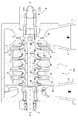
도 1은, 본 발명에 따른 임펠러들이 사용될 수 있는, 복수-스테이지 원심 압축기의 종단면도를 도시하고;
도 1a는 도 1의 압축기의 임펠러 블레이드의 확대도를 도시하며;
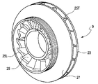
도 2는 도 1의 원심 압축기의 임펠러의 사시도를 도시하고;
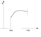
도 3은 자오면에서의 블레이드의 투영에 대한 개략도를 도시하며;
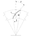
도 4는 임펠러 블레이드의 금속 각도를 한정하는 도면을 도시하고;
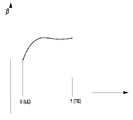
도 5 및 도 6은 축 방향을 따라 도 3의 블레이드의 블레이드 두께 및 금속 블레이드를 나타내는 도면을 도시하며;
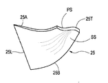
도 7은 본 개시에 따른 3-차원 블레이드의 사시도를 도시하고;
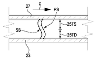
도 8은 본 개시에 따른 임펠러의 뒷전에 대한 반경 방향에서의 개략도를 도시하며;
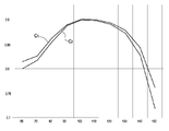
도 9는 현재 기술의 임펠러의 그리고 본 개시에 따른 임펠러의, 폴리트로프 효율(polytropic efficiency) 대 유동 계수에 대한 도면을 도시한다. A more complete appreciation of the disclosed embodiments of the invention and many of the attendant advantages thereof will be better appreciated by reference to the following detailed description when considered in connection with the accompanying drawings in which: By understanding, it will be easily obtained.
1 shows a longitudinal section view of a multi-stage centrifugal compressor in which the impellers according to the invention can be used;
Figure 1a shows an enlarged view of an impeller blade of the compressor of Figure 1;
2 shows a perspective view of an impeller of the centrifugal compressor of FIG. 1;
Figure 3 shows a schematic view of the projection of the blades in the meridional plane;
4 shows a view for defining the angle of a metal of an impeller blade;
Figures 5 and 6 show a view of the blade thickness of the blade of Figure 3 and the metal blade along the axial direction;
Figure 7 shows a perspective view of a three-dimensional blade according to the present disclosure;
8 shows a schematic view in the radial direction of the trailing edge of the impeller according to the present disclosure;
Figure 9 shows a plot of the polytropic efficiency versus flow coefficient of the impeller of the present technology and of the impeller according to the present disclosure.
예시적인 실시예들에 대한 뒤따르는 상세한 설명은 첨부되는 도면들을 참조한다. 상이한 도면들에서 동일한 참조 부호들은, 동일한 또는 유사한 요소들을 지시한다. 부가적으로, 도면들은 반드시 실척으로 작도되는 것은 아니다. 또한, 뒤따르는 상세한 설명은 본 발명을 제한하지 않는다. 대신에, 본 발명의 범위는 첨부되는 특허청구범위에 의해 한정된다. DETAILED DESCRIPTION The following detailed description of exemplary embodiments refers to the accompanying drawings. In the different drawings, the same reference numerals designate the same or similar elements. Additionally, the drawings are not necessarily drawn to scale. In addition, the following detailed description does not limit the present invention. Instead, the scope of the present invention is defined by the appended claims.
"일 실시예" 또는 "실시예" 또는 "일부 실시예"에 대한 명세서 전체에 걸친 기준은, 실시예와 관련하여 설명되는 특정 특징, 구조, 특성이, 개시된 대상의 적어도 하나의 실시예에 포함된다는 것을 의미한다. 따라서, 본 명세서 전체에 걸친 여러 장소에서의 "일 실시예에서" 또는 "실시예에서" 또는 "일부 실시예에서"와 같은 문구의 표현은, 반드시 동일한 실시예(들)를 참조하는 것은 아니다. 나아가, 특정의 특징들, 구조들 또는 특성들은, 하나 이상의 실시예에서, 임의의 적당한 방식으로 조합될 수 있을 것이다. It should also be understood that references throughout the specification for "one embodiment" or "an embodiment" or "some embodiments" are intended to be inclusive in a manner that is not intended to be limiting unless a particular feature, structure or characteristic described in connection with the embodiment is included in at least one embodiment . Accordingly, the appearances of the phrases "in one embodiment" or "in an embodiment" or "in some embodiments" in various places throughout this specification are not necessarily all referring to the same embodiment (s). Furthermore, certain features, structures, or characteristics may, in one or more embodiments, be combined in any suitable manner.
도 1 및 도 1a는, 본 명세서에 개시되는 대상이 실시될 수 있는, 전체적으로 참조 부호 '100'으로 지시되는, 복수-스테이지 원심 압축기의 예시적인 실시예를 도시한다. 도 1은, 압축기의 회전축(A-A)을 포함하는 평면에 따른 단면도를 도시하며 그리고 도 1a는 하나의 압축기 스테이지에 대한 확대도를 도시한다. Figures 1 and 1a illustrate an exemplary embodiment of a multi-stage centrifugal compressor, generally designated by the
압축기(100)는, 입구 매니폴드(2) 및 출구 매니폴드(3)를 갖도록 제공되는, 케이싱(1)을 구비한다. 케이싱(1) 내부에, 복수의 압축기 스테이지를 한정하는 여러 구성요소가 배열된다. The
더욱 구체적으로, 케이싱(1)은 압축기 로터를 수용한다. 압축기 로터는 로터 샤프트(5)를 포함하게 된다. 로터 샤프트(5)는 2개의 단부 베어링(6, 7)에 의해 지지될 수 있다. 압축기 로터는 추가로 적어도 하나의 임펠러를 포함한다. 도 1에 도시된 바와 같이, 일부 실시예에서, 압축기 로터는 복수의 임펠러(9)를 포함하며, 하나의 임펠러가 각각의 압축기 스테이지를 위한 것이다. 상기 임펠러들(9)은 2개의 베어링(6, 7) 사이에 배열된다. More specifically, the
제1 임펠러(9)의 유입구(9A)는 입구 공간(11: inlet plenum)과 유체 소통상태에 놓이며, 압축될 기체가 입구 매니폴드(2)를 통해 그 내부로 운반된다. 일부 실시예에서, 기체 유동은, 반경 방향으로 입구 공간(11)에 진입한 다음, 한 세트의 이동형 입구 가이드 베인(13)을 통해 운반되며, 그리고 실질적으로 축 방향으로 제1 임펠러(9)에 진입한다. The
도 1의 예시적인 실시예에 따르면, 마지막 임펠러(9)의 배출구(9B)는, 압축된 기체를 수집하고 이를 출구 매니폴드(3)를 향해 운반하는, 와류형성부(15: volute)와 유체 소통상태에 놓인다. According to the exemplary embodiment of Fig. 1, the
고정형 다이어프램들(17)이, 각 쌍의 연속적으로 배열되는 임펠러들(9) 사이에 배열된다. 다이어프램들(17)은, 별개의 축 방향으로 배열되는 구성요소들로서 형성될 수 있다. 다른 실시예에서, 다이어프램들(17)은, 2개의 실질적으로 대칭의 절반부로 형성될 수 있다. 각 다이어프램(17)은, 개별적인 상류측 임펠러(9)의 반경 방향 배출구로부터 개별적인 하류측 임펠러(9)의 유입구까지 연장되는, 복귀 채널(19) 및 확산기(18)를 한정한다. 확산기들(18) 내에서, 기체 유동은 느려지게 되며 그리고 임펠러로부터 기체로 전달되는 운동 에너지가 압력 에너지로 변환되며, 그에 따라 기체 압력을 증가시키도록 한다. Fixed diaphragms 17 are arranged between each pair of successively arranged
복귀 채널(19)은, 상류측 임펠러의 배출구로부터의 압축된 기체 유동을 하류측 임펠러의 유입구를 향해 복귀시킨다. 일부 실시예에서, 고정 블레이드들(20)이 확산기들(18) 내에 배열될 수 있다. 일부 실시예에서, 고정 블레이드들(21)이, 상류측 임펠러로부터 하류측 임펠러로 압축된 기체를 방향 전환하는 가운데 유동의 법선 방향 성분을 제거하기 위해, 복귀 채널들(19) 내에 제공될 수 있다. The
압축기(100)의 여러 압축 스테이지들 중 하나의 확대도가 도시되는 도 1a에 그리고 예시적인 임펠러가 부등각 투영도로 도시되는 도 2에 가장 잘 도시된 바와 같이, 각각의 임펠러(9)는, 허브 부분(23A)을 한정하는 디스크(23)를 포함하게 된다. 상기 허브 부분(23A)은 보어(23B)를 구비하며, 보어를 통해 로터 샤프트(5)가 연장된다. 디스크(23)는 또한 흔히, 전체로서 허브로 명명된다. 복수의 블레이드(25)가 디스크(23)로부터 연장되며 그리고 유동 채널들을 한정하고, 유동 채널들을 통해 기체가 유동하며 그리고 블레이드들(25)에 의해 가속된다. 각각의 블레이드는, 개별적으로 블레이드의 유입구 및 배출구에 배열되는, 앞전(25L) 및 뒷전(25T)을 구비한다. 일부 실시예에서, 임펠러(9)는 개발될 수 있다. 다른 실시예에서, 임펠러는, 디스크(23) 반대편에 배열되는 슈라우드(27)에 의해 폐쇄될 수 있으며, 블레이드들(25)은 디스크(23)와 슈라우드(27) 사이에서 연장된다. As shown best in FIG. 1A, in which an enlarged view of one of the various compression stages of the
각각의 블레이드(25)는, 앞전(25L)과 뒷전(25T) 사이에서 슈라우드(27)를 따라 연장되는 블레이드 팁(25A)을 갖도록 제공된다. 각각의 블레이드(25)는 추가로, 앞전(25L)과 뒷전(25T) 사이에서 디스크(23)를 따라 연장되는 블레이드 베이스 또는 블레이드 뿌리(blade root)를 갖도록 제공된다. Each of the
각각의 블레이드(25)는 흡입 측부 및 압력 측부를 구비하며, 그리고 블레이드의 형상은, 개별적으로 블레이드(25)의 캠버 라인 또는 중심 라인과 디스크(23) 및 슈라우드(27)의 교차점으로부터 출발하는, 이하에 설명되는 방식으로 한정된다. 도 3은 자오면에서의, 즉 R은 반경 방향이며 Z는 축 방향인 R-Z 평면에서의, 포괄적인 블레이드(25)의 투영도를 도시한다. 라인(L1)은, 디스크(23)에서의 블레이드 윤곽의 중심 라인의, 즉 캠버 라인의, 자오면(R-Z) 상에의 투영이다. 라인(L2)은, 슈라우드(27)에서의 블레이드 윤곽의 중심 라인의, 즉 캠버 라인의, 동일한 자오면(R-Z) 상에의 투영이다. Each
라인들(L1 L2)은 따라서, 개별적으로, 디스크와 슈라우드에서의, 즉 블레이드 베이스와 블레이드 팁에서의, R-Z 평면(자오면) 내에서의 블레이드 윤곽의 투영들이다. 도 3에, 블레이드의 뒷전(25T) 및 앞전(25L)의 투영이 또한 나타난다. The lines L1 L2 are therefore projections of the blade contour in the R-Z plane (meridian plane) at the disc and shroud, i.e., at the blade base and at the blade tip, individually. In Fig. 3, projection of the trailing
상기한 바와 같이, 임펠러(9)는, 도면들에 도시되는 예시적인 실시예에 도시된 바와 같이, 덮이게 될 수 있다. 그러나, 도시되지 않은 다른 실시예에서, 임펠러(9)는 개방되며 그리고 슈라우드(27)는 제공되지 않는다. 이러한 경우에, 라인(L2)은 단순히, 블레이드 팁(25A)에서의 캠버 라인 또는 중심 라인의 자오면(R-Z) 상에의 투영이다. As described above, the
이러한 라인들(L1, L2)은, 다음과 같이, 블레이드의 흡입 측부 및 압력 측부의 3차원 표면들을 설계하기 위한 출발점들이다. These lines L1 and L2 are starting points for designing the three-dimensional surfaces of the suction side and the pressure side of the blade, as follows.
2개의 라인(L1, L2)으로부터 출발하여, 블레이드의 흡입 측부 및 압력 측부를 한정하는 블레이드(25)의 대향하는 표면들의 실제 형상이, 2개의 부가적인 파라미터, 즉 블레이드 두께 및 블레이드 금속 각도에 의해, 결정된다. 파라미터들 양자 모두는 각각의 라인(L1, L2)을 따라 복수의 위치에 대해 한정된다. 일부 실시예에서, 블레이드 금속 각도 및 블레이드 두께는 라인(L1) 및 라인(L2)에 대해 상이한 값을 가질 수 있다. Starting from the two lines L1, L2, the actual shape of the opposing surfaces of the
고려되는 라인(L1) 또는 라인(L2)의 각 지점에서의 블레이드 금속 각도(β)는, 임펠러의 개략적 정면도를 도시하며 그리고 참조 부호 'L'은 고려되는 포괄적인 중심 라인인, 도 4에 도시된 바와 같이, 라인(L1) 또는 라인(L2)의 법선과 자오선 방향(M) 사이의 각도로서 정의된다. 화살표(F)는 임펠러의 회전 방향을 지시한다. 통상적으로, 각도(β)의 기호는, 임펠러의 회전 방향과 일치한다. 따라서, 도 4의 예에서, 자오선 방향(M)으로부터 시작하는 것으로 측정되며 그리고 임펠러의 회전 방향(화살표(F))과 반대임에 따라, 각도(β)는 음의 값이다. The blade metal angle? At each point of the line L1 or line L2 considered is shown in a schematic front view of the impeller and the reference letter 'L' Is defined as the angle between the normal of line L1 or line L2 and the meridional direction M, as shown. The arrow F indicates the rotational direction of the impeller. Normally, the sign of the angle? Coincides with the rotational direction of the impeller. Thus, in the example of Fig. 4, the angle beta is a negative value as measured from the meridional direction M and opposite to the direction of rotation of the impeller (arrow F).
블레이드의 두께(th)는, 고려되는 곡선(L1 또는 L2)의 각 지점에서 블레이드의 캠버 라인(즉, 중심 라인)으로부터, 블레이드의 흡입 측 표면 및 압력 측 표면 사이의 거리로서 정의된다. 도 5 및 도 6은, 예시적인 블레이드에 대한 금속 각도(β) 및 두께(th)의 분표를 개략적으로 도시한다. 도 5 및 도 6의 다이어그램의 수평축 상에, 자오선 방향을 따르는 표준화된 좌표가 도시된다. 좌표 "0"은 블레이드의 앞전에서의 위치를 지시하며 그리고 좌표 "1"은 뒷전에서의 위치를 지시한다. The thickness th of the blade is defined as the distance from the camber line (i.e., the center line) of the blade at each point of the curve L1 or L2 considered, between the suction side surface and the pressure side surface of the blade. Figures 5 and 6 schematically illustrate the spline of the metal angle [beta] and the thickness th for an exemplary blade. On the horizontal axis of the diagrams of Figures 5 and 6, normalized coordinates along the meridian direction are shown. The coordinate "0" indicates the position in front of the blade and the coordinate "1 " indicates the position in the trailing edge.
이상에서 정의된 파라미터들의 조합은, 블레이드 팁(25A) 및 블레이드 베이스(25B)에서의 블레이드의 윤곽을 제공한다. 블레이드의 압력 측부 및 흡입 측부의 표면을 한정하기 위한 다음 단계는 이제, 이상에서 한정된 블레이드 팁(25A) 및 블레이드 베이스(25B)에서의 2개의 블레이드의 윤곽으로부터 출발하는 2개의 대향하는 선직면의 생성이다. 선직면들은, 직선형의 라인으로, 블레이드 팁 윤곽의 각각의 지점을 블레이드 베이스 윤곽의 상응하는 지점과 연결함에 의해 생성된다. The combination of parameters defined above provides a profile of the blade at
블레이드의 기하 형상은, 곡선들(L1, L2) 및 상응하는 블레이드 팁 윤곽과 블레이드 베이스 윤곽이 일반적으로, 임펠러의 회전축 둘레에서 서로에 대해 블레이드 팁 윤곽 및 블레이드 베이스 윤곽을 회전시키도록, 법선 방향으로, 이동하게 됨에 따라, 즉 서로에 대해 위치 변경됨에 따라, 아직 완전히 한정되지 않는다. 그에 따라, 2개의 곡선(L1, L2)의 가능한 법선 방향 변위에 의해 주어지는, 추가적인 자유도가, 블레이드 기하 형성의 완전한 한정을 위해 이용 가능하다. 현재 기술의 임펠러들에서, 2개의 곡선(L1, L2)은, 법선 방향으로 이동, 즉 임펠러 축 둘레에서 서로에 대해 회전하게 되며, 그에 따라 자체의 직선형 형상을 유지하도록 (순수하게 반경 방향의 출구를 갖는 임펠러를 위해) 축 방향에 대해 뒷전(25T)을 경사지게 한다. 경사각으로 명명되는 축 방향에 대한 뒷전의 경사는, 이상에 언급된 파라미터들과 함께, 블레이드의 전체 기하 형상을 한정한다. The geometry of the blades is such that the curves L1 and L2 and the corresponding blade tip contours and blade base contours generally rotate in a direction normal to the blade axis to rotate the blade tip contours and blade base contours relative to one another about the axis of rotation of the impeller , As it is moved, i.e., displaced relative to one another. Accordingly, an additional degree of freedom, given by the possible normal direction displacements of the two curves L1, L2, is available for complete definition of blade geometry formation. In the impellers of the state of the art, the two curves L1 and L2 are arranged to move in the normal direction, i.e. to rotate about each other about the impeller axis, so as to maintain their straight shape (purely radial outlets The trailing
반대로, 본 명세서에 개시되는 대상에 따르면, 블레이드 팁 윤곽과 블레이드 베이스 윤곽 및 블레이드 팁 윤곽과 블레이드 베이스 윤곽 사이의 중간 윤곽들은 법선 방향으로 위치 변경되며, 따라서 뒷전(25T)은 비-직선형이 되며, 더욱 구체적으로 도 7에 사시도로 그리고 도 8에 측면도로 도시된 바와 같이 S-자형 윤곽을 취하게 된다. 더욱 구체적으로, 도 7은 관찰자를 바라보는 뒷전(25T)을 갖는 사시도로 단일 블레이드(25)를 도시한다. Conversely, according to the subject matter disclosed herein, the intermediate contours between the blade tip contour and the blade base contour and the blade tip contour and the blade base contour are repositioned in the normal direction, so that the trailing
뒷전(25T)은 제1 부분(25TD) 및 제2 부분(25TS)을 갖는다. 제1 부분(25TD)은 디스크(23)에 더 인접하게 위치하게 되며 그리고 제2 부분(25TS)은 슈라우드(27)에 더 인접하게 위치하게 된다(특히 도 8 참조). The trailing
일부 예시적인 실시예에서, 디스크(23)에 더 인접한 뒷전의 제1 부분(25TD)은 블레이드의 압력 측부(PS)를 바라보는 볼록함 및 블레이드의 흡입 측부(SS)를 바라보는 오목함을 구비한다. 블레이드의 압력 측부(PS)는 회전 방향(F)에 대해 전방 측부이며 그리고 블레이드의 흡입 측부(SS)는 회전 방향(F)에 대해 후방 측부, 즉 압력 측부 반대의 측부이다. 뒷전(25T)의 제2 부분(25TS)은 반대의 배열을 가지며, 압력 측부는 오목형이며 그리고 흡입 측부는 볼록형이다. In some exemplary embodiments, the
볼록함이 디스크 인근에서 흡입 측부를 그리고 슈라우드 근처에서 압력 측부를 바라보는, 반대의 배열이 배제되지 않는다. The convexity does not exclude the opposite arrangement, looking at the suction side near the disk and the pressure side near the shroud.
일부 실시예에서, 뒷전의 제1 부분 및 제2 부분은 굴곡 지점에서 서로 병합되며, 따라서 전체 뒷전은 곡선이며 그리고 직선형 부분들이 전혀 없다. In some embodiments, the first portion and the second portion of the trailing edge are merged with each other at the inflection point, so that the trailing edge is curved and there are no straight portions at all.
뒷전의 S-자 형상 구성은, 법선 방향으로, 즉 임펠러의 회전축 둘레에서, 뒷전의 각 지점을 위치 변경시키기 위한 적당한 규정을 제공함에 의해, 달성된다. 실제로, 뒷전의 형상은, 블레이드 베이스 윤곽으로부터 (또는 블레이드 팁 윤곽으로부터) 시작하여, 뒷전을 따르는 복수의 지점들의 법선 방향으로의 이동시키며, 그리고 상기 지점들을 보간법(interpolation)에 의해 연결함으로써, 달성될 수 있다. 법선 방향으로의 뒷전의 여러 지점의 변위는, 라인들(L1, L2) 및 이들을 따르는 블레이드 두께와 금속 각도로부터 획득되는 블레이드 베이스 윤곽 및 블레이드 팁 윤곽으로부터 출발하는 선직면들과 같이 앞서 생성되는, 압력 측 표면 및 흡입 측 표면의 남아 있는 지점들의 강체 변위(rigid displacement)를 야기한다. The S-shaped configuration of the trailing edge is achieved by providing appropriate provisions for repositioning each trailing edge in the normal direction, i.e. around the rotational axis of the impeller. Indeed, the shape of the trailing edge can be achieved by starting from the blade base contour (or from the blade tip contour), moving in the normal direction of the plurality of points along the trailing edge, and connecting the points by interpolation . The displacements of the various points in the trailing direction in the direction of the normal are defined as the blade base contour obtained from the lines L1 and L2 and the blade thickness and metal angle following them, Resulting in rigid displacement of the remaining points of the side surface and suction side surface.
최종 결과로서, 임펠러의 압력 측부 및 흡입 측부 양자 모두의 전체 표면은, 이중 곡률을 갖는 비-선직면들이 된다. As a net result, the entire surface of both the pressure side and suction side of the impeller becomes non-linear faces with double curvature.
블레이드의 뒷전(25T)의 이중의 S-자형 곡률은 손실을 감소시켜, 압축기의 폴리트로프 효율을 개선하도록 한다. 이는, S-자 형상 뒷전(곡선(C1))을 갖는 임펠러를 사용하는 압축 스테이지의 그리고 직선형 뒷전(곡선(C2))을 갖는 임펠러를 사용하는 압축 스테이지의, 폴리트로프 효율 대 유동 계수를 예시하는 도 9로부터 인식될 수 있다. 비-설계 조건(100 미만 또는 초과의 유동 계수)에서, S-자 형상 뒷전들(25T)을 갖는 임펠러의 폴리트로프 효율은, 직선형 뒷전들을 갖는 현재 기술의 설계를 넘어 현저하게 개선된다. The double S-shaped curvature of the trailing edge (25T) of the blade reduces losses, thereby improving the polytropic efficiency of the compressor. This shows that the compression stage using an impeller with an S-shaped trailing edge (curve C1) and a compression stage using an impeller with a straight trailing edge (curve C2) Can be recognized from Fig. In non-design conditions (flow coefficients less than or equal to 100), the polytropic efficiency of the impeller with S-shaped trailing
비록 본 명세서에 설명되는 대상에 대한 개시된 실시예들은 도면들에 도시되었으며 그리고 여러 예시적인 실시예들에 관련하여 특히 그리고 상세하게 이상에서 충분히 설명되었지만, 많은 수정들, 변경들, 및 생략들이, 여기에 기술되는 신규의 교시들, 원리들 및 개념들, 그리고 첨부 특허청구범위에 인용되는 본 발명의 이점들로부터 실질적으로 벗어남 없이, 가능하다는 것이, 당업자들에게 명백할 것이다. 그에 따라, 개시된 혁신들의 적절한 범위는, 모든 그러한 수정들, 변경들, 및 생략들을 포괄하도록, 첨부 특허청구범위의 가장 넓은 해석에 의해서만 결정되어야 할 것이다. 다양한 실시예들의 상이한 특징들, 구조들 및 수단들이 상이하게 조합될 수 있다. Although the disclosed embodiments of the subject matter described herein have been illustrated in the drawings and have been described fully and in detail in detail above in connection with several exemplary embodiments, many modifications, changes, Without departing substantially from the novel teachings, principles and concepts described in the claims, and the advantages of the present invention as recited in the appended claims. Accordingly, the appropriate scope of the disclosed innovations should be determined only by the broadest interpretation of the appended claims, including all such modifications, alterations, and omissions. The different features, structures and means of various embodiments may be combined differently.
Claims (7)
유입구;
배출구;
상기 유입구로부터 상기 배출구까지 연장되는 디스크;
상기 디스크로부터 연장되는 복수의 블레이드로서, 각각의 블레이드는, 상기 유입구에의 앞전; 상기 배출구에의 뒷전; 상기 앞전과 상기 뒷전 사이에서 상기 디스크를 따라 연장되는 블레이드 베이스; 상기 앞전과 상기 뒷전 사이에서 연장되는 상기 디스크 반대편의 블레이드 팁; 압력 측부; 및 흡입 측부를 포함하는 것인, 복수의 블레이드
를 포함하며,
상기 뒷전은, 오목 부분, 볼록 부분 및 이들 사이의 굴곡 지점을 구비하는, S-자 형상인 것인, 원심 압축기 임펠러.As a centrifugal compressor impeller,
Inlet;
outlet;
A disk extending from the inlet to the outlet;
A plurality of blades extending from the disc, each blade having a leading edge to the inlet; A trailing edge to said outlet; A blade base extending along the disk between the leading and trailing edges; A blade tip opposite the disk extending between the leading and trailing edges; Pressure side; And a suction side, wherein the plurality of blades
/ RTI >
Wherein the trailing edge is S-shaped, having a concave portion, a convex portion and a bending point therebetween.
상기 뒷전의 상기 오목 부분 및 상기 볼록 부분은, 상기 블레이드 베이스 근처의 상기 뒷전의 제1 부분이 상기 블레이드의 압력 측부를 바라보는 볼록함을 갖도록 그리고 상기 블레이드 베이스로부터 멀리 떨어진 상기 뒷전의 제2 부분이 상기 블레이드의 흡입 측부를 바라보는 볼록함을 갖도록, 배열되는 것인, 원심 압축기 임펠러.The method according to claim 1,
Wherein the recessed portion and the convex portion of the trailing shear are formed such that a first portion of the trailing edge near the blade base has a convexity that faces the pressure side of the blade and a second portion of the trailing edge away from the blade base Wherein the blades are arranged so as to have a convexity facing the suction side of the blades.
상기 뒷전은, 상기 블레이드 베이스와 상기 블레이드 팁 사이에서, 자체의 전체 길이를 따라 전체적으로 만곡되며, 그리고 어떠한 직선형 섹션도 전혀 없는 것인, 원심 압축기 임펠러.3. The method according to claim 1 or 2,
Wherein the trailing edge is entirely curved along its entire length between the blade base and the blade tip and has no straight section at all.
각각의 상기 블레이드는, 상기 압력 측부와 상기 흡입 측부 양자 모두에서 이중의 곡률에 따라 전체적으로 만곡되며, 그리고 선직면들에서 벗어난 것인, 원심 압축기 임펠러.4. The method according to any one of claims 1 to 3,
Each of said blades being generally curved in accordance with a double curvature in both said pressure side and said suction side, and deviating from proximal surfaces.
제 1항 내지 제 4항 중 어느 한 항에 따른 적어도 하나의 임펠러, 및
상기 임펠러의 배출구 둘레에 배열되는 확산기
를 포함하는 것인, 원심 압축기.As a centrifugal compressor,
At least one impeller according to any one of claims 1 to 4, and
A diffuser disposed around the outlet of the impeller,
And a centrifugal compressor.
임펠러 디스크를 따라 블레이드 베이스 윤곽을 그리고 자오면 내에 블레이드 팁 윤곽을 한정하는 단계;
상기 블레이드 베이스 윤곽과 상기 블레이드 팁 윤곽 사이에서 연장되는 선직면으로서 압력 측 표면 및 흡입 측 표면을 한정하는 단계로서, 상기 압력 측 표면 및 상기 흡입 측 표면은 상기 블레이드의 직선형 뒷전과 직선형 앞전 사이에서 연장되는 것인, 압력 측 표면 및 흡입 측 표면을 한정 단계;
법선 방향을 따라 상기 뒷전의 지점들을 변위시킴에 의해 상기 선직면들을 비-선직면들로 변환하는 단계로서, 그에 따라 상기 뒷전에, 오목 부분, 볼록 부분 및 이들 사이의 굴곡 지점을 구비하는 S-자 형상을 부과하도록 하는 것인, 변환하는 단계;
를 포함하는 것인, 압축기 임펠러를 설계하는 방법. A method of designing a compressor impeller,
Defining a blade base profile along the impeller disk and defining a blade tip contour within the meridian plane;
Defining a pressure side surface and a suction side surface as a straight surface extending between the blade base contour and the blade tip contour, wherein the pressure side surface and the suction side surface extend between a straight trailing edge of the blade and a straight edge edge of the blade Defining a pressure-side surface and a suction-side surface;
Transforming the linear faces into non-linear faces by displacing the points in the trailing edge along a normal direction, whereby in the trailing edge the S-shaped beam having a concave portion, a convex portion and a bending point therebetween, Shaped shape, the method comprising the steps of:
Wherein the compressor impeller comprises a plurality of compressors.
상기 뒷전의 상기 오목 부분 및 상기 볼록 부분은, 블레이드 베이스 근처의 상기 뒷전의 제1 부분이 상기 블레이드의 압력 측부를 바라보는 볼록함을 갖도록 그리고 상기 블레이드 베이스로부터 멀리 떨어진 상기 뒷전의 제2 부분이 상기 블레이드의 흡입 측부를 향한 볼록함을 갖도록, 배열되는 것인, 압축기 임펠러를 설계하는 방법.
The method according to claim 6,
Wherein the concave portion and the convex portion of the trailing sheath are formed such that the first portion of the trailing edge near the blade base has a convexity facing the pressure side of the blade and the second portion of the trailing edge farther from the blade base The convexities being directed toward the suction side of the blades.
Applications Claiming Priority (3)
| Application Number | Priority Date | Filing Date | Title |
|---|---|---|---|
| ITFI2013A000261 | 2013-10-28 | ||
| IT000261A ITFI20130261A1 (en) | 2013-10-28 | 2013-10-28 | "CENTRIFUGAL COMPRESSOR IMPELLER WITH BLADES HAVING AN S-SHAPED TRAILING EDGE" |
| PCT/EP2014/072997 WO2015063027A1 (en) | 2013-10-28 | 2014-10-27 | Centrifugal compressor impeller with blades having an s-shaped trailing edge |
Publications (1)
| Publication Number | Publication Date |
|---|---|
| KR20160077101A true KR20160077101A (en) | 2016-07-01 |
Family
ID=49920417
Family Applications (1)
| Application Number | Title | Priority Date | Filing Date |
|---|---|---|---|
| KR1020167012951A KR20160077101A (en) | 2013-10-28 | 2014-10-27 | Centrifugal compressor impeller with blades having an s-shaped trailing edge |
Country Status (11)
| Country | Link |
|---|---|
| US (1) | US20160252101A1 (en) |
| EP (1) | EP3063414B1 (en) |
| JP (1) | JP2016535194A (en) |
| KR (1) | KR20160077101A (en) |
| CN (1) | CN105917123B (en) |
| CA (1) | CA2927538A1 (en) |
| DK (1) | DK3063414T3 (en) |
| IT (1) | ITFI20130261A1 (en) |
| MX (1) | MX2016005523A (en) |
| RU (1) | RU2669425C2 (en) |
| WO (1) | WO2015063027A1 (en) |
Families Citing this family (6)
| Publication number | Priority date | Publication date | Assignee | Title |
|---|---|---|---|---|
| JP6168705B2 (en) * | 2014-12-10 | 2017-07-26 | 三菱重工業株式会社 | Centrifugal compressor impeller |
| JP2017172344A (en) * | 2016-03-18 | 2017-09-28 | 三菱重工業株式会社 | Impeller, rotary machine, and process of manufacturing impeller |
| US10415584B2 (en) * | 2017-10-20 | 2019-09-17 | Minebea Mitsumi Inc. | Impeller and fan using the same |
| US11421702B2 (en) | 2019-08-21 | 2022-08-23 | Pratt & Whitney Canada Corp. | Impeller with chordwise vane thickness variation |
| US20240060507A1 (en) * | 2022-08-22 | 2024-02-22 | FoxRES LLC | Sculpted Low Solidity Vaned Diffuser |
| DE102022127147A1 (en) | 2022-10-17 | 2024-04-18 | Man Energy Solutions Se | Compressors and turbochargers |
Family Cites Families (15)
| Publication number | Priority date | Publication date | Assignee | Title |
|---|---|---|---|---|
| FR2205949A5 (en) * | 1972-11-06 | 1974-05-31 | Cit Alcatel | |
| SU606010A1 (en) * | 1976-02-23 | 1978-05-05 | Ленинградский Ордена Ленина Политехнический Институт Им.М.И.Калинина | Centrifugal compressor runner |
| SU1112152A1 (en) * | 1983-05-12 | 1984-09-07 | Ленинградский Ордена Ленина Политехнический Институт Им.М.И.Калинина | Impeller for centrifugal compressor |
| JP3482668B2 (en) * | 1993-10-18 | 2003-12-22 | 株式会社日立製作所 | Centrifugal fluid machine |
| CN1236196C (en) * | 1994-06-10 | 2006-01-11 | 株式会社荏原制作所 | Centrifugal or mixed-flow turbine machinery |
| JPH1122695A (en) * | 1997-06-30 | 1999-01-26 | Ishikawajima Harima Heavy Ind Co Ltd | Impeller blade structure of centrifugal compressor |
| USD421798S (en) * | 1999-08-11 | 2000-03-21 | Te Liang | Radiating fan |
| CN2535587Y (en) * | 2002-02-01 | 2003-02-12 | 海尔集团公司 | Positive-negative air-blowing through flow fan |
| US7147433B2 (en) * | 2003-11-19 | 2006-12-12 | Honeywell International, Inc. | Profiled blades for turbocharger turbines, compressors, and the like |
| JP4612084B2 (en) * | 2008-08-29 | 2011-01-12 | 株式会社日立産機システム | Centrifugal fan and air fluid machine using the same |
| JP5342385B2 (en) * | 2009-09-15 | 2013-11-13 | 三菱電機株式会社 | Fan, electric blower equipped with the fan, and electric vacuum cleaner using the electric blower |
| JP5730649B2 (en) * | 2011-04-13 | 2015-06-10 | 株式会社日立製作所 | Impeller and turbomachine having the same |
| US8951009B2 (en) * | 2011-05-23 | 2015-02-10 | Ingersoll Rand Company | Sculpted impeller |
| US8997486B2 (en) * | 2012-03-23 | 2015-04-07 | Bullseye Power LLC | Compressor wheel |
| JP5882804B2 (en) * | 2012-03-23 | 2016-03-09 | 三菱重工業株式会社 | Impeller and fluid machinery |
-
2013
- 2013-10-28 IT IT000261A patent/ITFI20130261A1/en unknown
-
2014
- 2014-10-27 CN CN201480059438.5A patent/CN105917123B/en active Active
- 2014-10-27 MX MX2016005523A patent/MX2016005523A/en unknown
- 2014-10-27 EP EP14790070.8A patent/EP3063414B1/en active Active
- 2014-10-27 CA CA2927538A patent/CA2927538A1/en not_active Abandoned
- 2014-10-27 JP JP2016526022A patent/JP2016535194A/en active Pending
- 2014-10-27 RU RU2016114806A patent/RU2669425C2/en active
- 2014-10-27 DK DK14790070.8T patent/DK3063414T3/en active
- 2014-10-27 KR KR1020167012951A patent/KR20160077101A/en not_active Application Discontinuation
- 2014-10-27 US US15/032,846 patent/US20160252101A1/en not_active Abandoned
- 2014-10-27 WO PCT/EP2014/072997 patent/WO2015063027A1/en active Application Filing
Also Published As
| Publication number | Publication date |
|---|---|
| CA2927538A1 (en) | 2015-05-07 |
| RU2016114806A3 (en) | 2018-05-25 |
| RU2016114806A (en) | 2017-12-05 |
| ITFI20130261A1 (en) | 2015-04-29 |
| JP2016535194A (en) | 2016-11-10 |
| DK3063414T3 (en) | 2023-06-26 |
| WO2015063027A1 (en) | 2015-05-07 |
| US20160252101A1 (en) | 2016-09-01 |
| EP3063414A1 (en) | 2016-09-07 |
| MX2016005523A (en) | 2016-08-03 |
| CN105917123B (en) | 2018-09-21 |
| RU2669425C2 (en) | 2018-10-11 |
| CN105917123A (en) | 2016-08-31 |
| EP3063414B1 (en) | 2023-05-24 |
Similar Documents
| Publication | Publication Date | Title |
|---|---|---|
| EP3092413B1 (en) | Centrifugal compressor impeller with non-linear blade leading edge and associated design method | |
| US8192168B2 (en) | Airfoil shape for a compressor blade | |
| US8038390B2 (en) | Airfoil shape for a compressor | |
| RU2581686C2 (en) | Radial diffuser blade for centrifugal compressors | |
| KR20160077101A (en) | Centrifugal compressor impeller with blades having an s-shaped trailing edge | |
| US8491260B2 (en) | Airfoil shape for a compressor vane | |
| US8591193B2 (en) | Airfoil shape for a compressor blade | |
| US20080107534A1 (en) | Airfoil shape for a compressor | |
| US20080101957A1 (en) | Airfoil shape for a compressor | |
| US9963973B2 (en) | Blading | |
| CN102454633B (en) | Axial compressor | |
| JP7104379B2 (en) | Axial flow type fan, compressor and turbine blade design method, and blades obtained by the design | |
| US10221858B2 (en) | Impeller blade morphology | |
| US10100841B2 (en) | Centrifugal compressor and system | |
| KR102376903B1 (en) | Blade, compressor and gas turbine having the same | |
| JP2017172569A (en) | Axial flow compressor |
Legal Events
| Date | Code | Title | Description |
|---|---|---|---|
| WITN | Application deemed withdrawn, e.g. because no request for examination was filed or no examination fee was paid |