KR20160076331A - Remote apparatus of distributed antenna system - Google Patents
Remote apparatus of distributed antenna system Download PDFInfo
- Publication number
- KR20160076331A KR20160076331A KR1020140186412A KR20140186412A KR20160076331A KR 20160076331 A KR20160076331 A KR 20160076331A KR 1020140186412 A KR1020140186412 A KR 1020140186412A KR 20140186412 A KR20140186412 A KR 20140186412A KR 20160076331 A KR20160076331 A KR 20160076331A
- Authority
- KR
- South Korea
- Prior art keywords
- signal
- downlink
- unit
- signals
- amplifying
- Prior art date
Links
Images

Classifications
-
- H—ELECTRICITY
- H04—ELECTRIC COMMUNICATION TECHNIQUE
- H04B—TRANSMISSION
- H04B10/00—Transmission systems employing electromagnetic waves other than radio-waves, e.g. infrared, visible or ultraviolet light, or employing corpuscular radiation, e.g. quantum communication
- H04B10/25—Arrangements specific to fibre transmission
- H04B10/2575—Radio-over-fibre, e.g. radio frequency signal modulated onto an optical carrier
- H04B10/25751—Optical arrangements for CATV or video distribution
-
- H—ELECTRICITY
- H04—ELECTRIC COMMUNICATION TECHNIQUE
- H04B—TRANSMISSION
- H04B10/00—Transmission systems employing electromagnetic waves other than radio-waves, e.g. infrared, visible or ultraviolet light, or employing corpuscular radiation, e.g. quantum communication
- H04B10/40—Transceivers
Landscapes
- Engineering & Computer Science (AREA)
- Physics & Mathematics (AREA)
- Electromagnetism (AREA)
- Computer Networks & Wireless Communication (AREA)
- Signal Processing (AREA)
- Multimedia (AREA)
- Mobile Radio Communication Systems (AREA)
Abstract
Description
본 발명의 기술적 사상은 분산 안테나 시스템의 리모트 장치에 관한 것이다. 보다 상세하게는, 본 발명의 기술적 사상은 기지국으로부터 직접 기지국 신호를 수신하여 서비스할 수 있는 분산 안테나 시스템의 리모트 장치에 관한 것이다.
The technical idea of the present invention relates to a remote device of a distributed antenna system. More particularly, the technical idea of the present invention relates to a remote apparatus of a distributed antenna system capable of receiving and servicing a base station signal directly from a base station.
일반적으로, 이동통신의 발달과 함께 이용자들의 이용 형태와 요구 또한 다양해져 이용자들이 시간과 공간에 제약을 받지 않고 통신하기를 원하고 있다. 그러나 기지국의 한정된 출력과 기지국의 위치나 지형 등의 제약으로 인해 음영지역(shadow area)이 발생하면서 서비스 제공자가 사용자들에게 원활한 통신 서비스를 제공하기 어려운 문제가 있었고, 이를 해소하기 위한 방안으로서 분산 안테나 시스템(Distributed Antenna System, DAS)이 이용되고 있다.Generally, with the development of mobile communication, users' usage patterns and demands are also diversified so that users want to communicate without restriction of time and space. However, there has been a problem that it is difficult for the service provider to provide a smooth communication service to the users due to the limited output of the base station and the limitation of the position and topography of the base station, and shadow areas are generated. In order to solve this problem, System (Distributed Antenna System, DAS) is used.
분산 안테나 시스템은, 기지국과 통신적으로 커플된 헤드엔드 장치 및 헤드엔드 장치와 광 케이블을 통해 커플된 리모트 장치를 포함하고, 빌딩 내부, 빌딩 지하, 지하철, 터널, 주거지역의 아파트단지 등 전파가 수신되지 않거나 전파 수신이 약한 지역에 설치되어 기지국의 신호가 도달하기 어려운 음영지역에까지 통신 서비스를 제공함으로써, 기지국의 커버리지를 확장시키고 있다.A distributed antenna system includes a head end device communicatively coupled to a base station, and a remote device coupled to the head end device through an optical cable. The distributed antenna system includes a radio wave such as a building inside, a building underground, a subway, a tunnel, The coverage of the base station is expanded by providing a communication service to a shaded area that is not received or installed in an area where reception of radio waves is weak and the signal of the base station is difficult to reach.
분산 안테나 시스템을 구성하는 리모트 장치는 헤드엔드 장치로부터 전송되는 광 신호를 RF 신호로 변환 및 증폭하여 사용자 단말로 재전송하는 수동적인 역할만을 수행하고 있는데, 헤드엔드 장치의 오작동, 광 선로의 이상 등과 같은 운용 상의 문제 발생 시에도 사용자들에게 안정적으로 서비스를 제공하기 위해서, 또는 설치 환경 상의 제약으로 인해 헤드엔드 장치와의 연결이 어려운 경우 등에 유연하게 대응하기 위해서, 리모트 장치의 기능이 확장될 필요가 있다.
The remote device constituting the distributed antenna system performs only a passive role of converting an optical signal transmitted from the head end device into an RF signal and amplifying the RF signal and retransmitting the RF signal to the user terminal. The function of the remote device needs to be expanded in order to provide a stable service to the users even in the event of a problem in operation or to flexibly cope with a case where it is difficult to connect to the head end device due to restrictions on the installation environment .
본 발명의 기술적 사상에 따른 분산 안테나 시스템의 리모트 장치가 이루고자 하는 기술적 과제는, 헤드엔드 장치로부터 전송되는 광 신호를 신호 처리 후 사용자 단말로 전송할 수 있을 뿐만 아니라 직접 기지국으로부터 전송되는 RF 신호를 수신하여 신호 처리한 후 사용자 단말로 전송할 수 있는 리모트 장치를 제공하는 것을 목적으로 한다.
A remote device of a distributed antenna system according to the technical idea of the present invention is capable of not only transmitting an optical signal transmitted from a head end apparatus to a user terminal after signal processing but also receiving an RF signal transmitted from a direct base station And a remote device capable of performing signal processing and transmitting the signal to a user terminal.
본 발명의 기술적 사상에 의한 일 양태에 따른 리모트 장치는, 제1 다운링크 신호를 입력받는 제1 신호 분기부; 다운링크 광 신호를 입력받고, 상기 다운링크 광 신호를 제2 다운링크 신호로 변환하는 광 송수신부; 상기 제1 신호 분기부와 연결되는 제1 입력 단자 및 상기 광 송수신부와 연결되는 제2 입력 단자와, 출력 단자 사이의 연결을 스위칭하는 제1 스위치부; 상기 제1 입력 단자 또는 상기 제2 입력 단자가 상기 출력 단자에 연결되도록 상기 제1 스위치부를 제어하는 제어부; 및 상기 출력 단자로부터 출력되는 상기 제1 다운링크 신호 또는 상기 제2 다운링크 신호를 증폭하는 증폭부;를 포함한다.According to an aspect of the present invention, there is provided a remote apparatus comprising: a first signal branching unit receiving a first downlink signal; An optical transceiver receiving a downlink optical signal and converting the downlink optical signal into a second downlink signal; A first switch unit for switching a connection between an output terminal and a first input terminal connected to the first signal branching unit, a second input terminal connected to the optical transceiver unit, A control unit for controlling the first switch unit such that the first input terminal or the second input terminal is connected to the output terminal; And an amplifying unit amplifying the first downlink signal or the second downlink signal output from the output terminal.
일부 실시예에서, 상기 제1 신호 분기부는, 기지국으로부터 전송되는 상기 제1 다운링크 신호를 입력받을 수 있고, 상기 광 송수신부는, 통신적으로 결합된(communicatively coupled) 헤드엔드 장치로부터 상기 다운링크 광 신호를 입력받을 수 있고, 상기 다운링크 광 신호를 상기 제2 다운링크 신호로 변환할 수 있다.In some embodiments, the first signal splitting unit may receive the first downlink signal transmitted from the base station, and the optical transmitting / receiving unit may receive the downlink optical signal from a communicatively coupled head end apparatus, Signal, and convert the downlink optical signal into the second downlink signal.
일부 실시예에서, 상기 제1 다운링크 신호는, 상기 제2 다운링크 신호에 포함된 복수의 RF(Radio Frequency) 신호들 각각의 주파수 대역과 대응하는 주파수 대역을 갖되 상기 제2 다운링크 신호에 포함된 복수의 RF 신호들 각각의 채널과 동일한 채널을 이용하는 복수의 RF 신호들을 포함할 수 있다.In some embodiments, the first downlink signal has a frequency band corresponding to a frequency band of each of a plurality of RF (Radio Frequency) signals included in the second downlink signal, but is included in the second downlink signal And a plurality of RF signals using the same channel as each channel of the plurality of RF signals.
일부 실시예에서, 상기 증폭부는, 상기 제1 다운링크 신호 또는 상기 제2 다운링크 신호에 포함된 서로 다른 주파수 대역의 복수의 RF 신호들 중 대응하는 주파수 대역의 RF 신호를 증폭하는 복수의 서브 증폭부;를 포함할 수 있다.In some embodiments, the amplification unit includes a plurality of sub-amplifiers for amplifying RF signals of a corresponding frequency band among a plurality of RF signals of different frequency bands included in the first downlink signal or the second downlink signal, And the like.
일부 실시예에서, 상기 복수의 서브 증폭부는, 서로 캐스케이드 구조로 연결될 수 있다.In some embodiments, the plurality of sub-amplifiers may be connected to each other in a cascade structure.
일부 실시예에서, 상기 복수의 서브 증폭부 중 적어도 하나는, 상기 제1 다운링크 신호 또는 상기 제2 다운링크 신호를 분할하여 후단에 연결된 서브 증폭부로 전달하는 제1 분배/결합기; 상기 제1 분배/결합기로부터 전달되는 상기 제1 다운링크 신호 또는 상기 제2 다운링크 신호를 필터링하여 대응하는 주파수 대역의 RF 신호를 출력하는 제1 필터; 및 상기 제1 필터로부터 출력되는 RF 신호를 증폭하는 제1 증폭기;를 포함할 수 있다.In some embodiments, at least one of the plurality of sub-amplifying units includes a first distributing / combining unit for dividing the first downlink signal or the second downlink signal and transmitting the divided signal to a sub-amplifying unit connected to a subsequent stage; A first filter for filtering the first downlink signal or the second downlink signal transmitted from the first distributor / combiner and outputting an RF signal of a corresponding frequency band; And a first amplifier for amplifying the RF signal output from the first filter.
일부 실시예에서, 상기 리모트 장치는, 상기 복수의 서브 증폭부 각각에 의해 증폭된 복수의 RF 신호를 결합하는 제2 신호 분기부;를 더 포함할 수 있다.In some embodiments, the remote device may further include a second signal branching unit for combining a plurality of RF signals amplified by each of the plurality of sub-amplifying units.
일부 실시예에서, 상기 리모트 장치는, 상기 증폭부와 연결되는 입력 단자와, 상기 제1 신호 분기부와 연결되는 제1 출력 단자 및 상기 광 송수신부와 연결되는 제2 출력 단자 사이의 연결을 스위칭하는 제2 스위치부; 및 입력되는 업링크 신호를 서로 다른 대역의 복수의 RF 신호들로 분리하는 제2 신호 분기부;를 더 포함할 수 있되, 상기 증폭부는, 상기 제2 신호 분기부로부터 출력되는 상기 복수의 RF 신호들을 증폭할 수 있고, 상기 제어부는, 상기 제2 스위치부의 입력 단자가 상기 제1 출력 단자 또는 상기 제2 출력 단자에 연결되도록 상기 제2 스위치부를 제어할 수 있다.In some embodiments, the remote device may switch a connection between an input terminal connected to the amplification section, a first output terminal connected to the first signal branching section, and a second output terminal connected to the optical transceiver section, A second switch unit for switching the first switch unit; And a second signal branching unit for separating the input uplink signal into a plurality of RF signals of different bands, wherein the amplifying unit further comprises: a plurality of RF signals output from the second signal branching unit, And the control unit may control the second switch unit such that an input terminal of the second switch unit is connected to the first output terminal or the second output terminal.
일부 실시예에서, 상기 제어부는, 상기 제1 신호 분기부와 상기 광 송수신부 중 상기 제1 스위치부를 통해 상기 증폭부와 연결되는 구성이 상기 제2 스위치부를 통해 상기 증폭부와 연결되도록 상기 제2 스위치부를 제어할 수 있다.In some embodiments, the control unit may be configured such that a configuration of the first signal branching unit and the optical transmitting / receiving unit connected to the amplifying unit via the first switch unit is connected to the amplifying unit through the second switch unit, The switch unit can be controlled.
일부 실시예에서, 상기 증폭부는, 입력되는 상기 복수의 RF 신호들 중 대응하는 주파수 대역의 RF 신호를 증폭하는 복수의 서브 증폭부;를 포함할 수 있다.In some embodiments, the amplification unit may include a plurality of sub-amplifiers for amplifying an RF signal of a corresponding frequency band among the plurality of input RF signals.
일부 실시예에서, 상기 복수의 서브 증폭부 중 적어도 하나는, 입력되는 RF 신호의 노이즈를 제거하여 출력하는 제2 필터; 상기 제2 ?터로부터 출력되는 RF 신호와 전단에 연결된 서브 증폭부로부터 전달되는 RF 신호를 결합하는 제2 분배/결합기; 및 상기 제2 분배/결합기로부터 출력되는 결합된 RF 신호를 증폭하는 제2 증폭기;를 포함할 수 있다.In some embodiments, at least one of the plurality of sub-amplifying units includes a second filter that removes noise from an input RF signal and outputs the noise; A second distributor / combiner for combining an RF signal output from the second detector and an RF signal transmitted from a sub-amplifier connected to a previous stage; And a second amplifier for amplifying a combined RF signal output from the second distributor / combiner.
일부 실시예에서, 상기 제어부는, 관리자의 입력 또는 관리 서버로부터 전송되는 제어 신호에 응답하여, 상기 제1 입력 단자 또는 상기 제2 입력 단자가 상기 출력 단자에 연결되도록 상기 제1 스위치부를 제어할 수 있다.
In some embodiments, the control unit can control the first switch unit such that the first input terminal or the second input terminal is connected to the output terminal, in response to a control signal transmitted from an administrator input or management server have.
본 발명의 기술적 사상에 의한 다른 양태에 따른 리모트 장치는, 제1 다운링크 신호를 입력받는 제1 신호 분기부; 다운링크 광 신호를 입력받고, 상기 다운링크 광 신호를 제2 다운링크 신호로 변환하는 광 송수신부; 상기 제1 및 제2 다운링크 신호를 입력받고, 상기 제1 및 제2 다운링크 신호를 결합하여 제3 다운링크 신호를 생성하는 결합부; 및 상기 제3 다운링크 신호를 입력받고, 상기 제3 다운링크 신호를 증폭하는 증폭부;를 포함한다.According to another aspect of the present invention, there is provided a remote apparatus comprising: a first signal branching unit receiving a first downlink signal; An optical transceiver receiving a downlink optical signal and converting the downlink optical signal into a second downlink signal; A combining unit for receiving the first and second downlink signals and combining the first and second downlink signals to generate a third downlink signal; And an amplifying unit receiving the third downlink signal and amplifying the third downlink signal.
일부 실시예에서, 상기 제1 신호 분기부는, 기지국으로부터 전송되는 상기 제1 다운링크 신호를 입력받을 수 있고, 상기 광 송수신부는, 통신적으로 결합된 헤드엔드 장치로부터 상기 다운링크 광 신호를 입력받고, 상기 다운링크 광 신호를 상기 제2 다운링크 신호로 변환할 수 있다.In some embodiments, the first signal splitting unit can receive the first downlink signal transmitted from the base station, and the optical transmitting / receiving unit receives the downlink optical signal from the communicatively coupled head end apparatus , And convert the downlink optical signal into the second downlink signal.
일부 실시예에서, 상기 제1 다운링크 신호는, 상기 제2 다운링크 신호에 포함된 복수의 RF 신호들 각각의 주파수 대역과 대응하는 주파수 대역을 갖되 상기 제2 다운링크 신호에 포함된 복수의 RF 신호들 각각의 채널과 다른 채널을 이용하는 복수의 RF 신호들을 포함할 수 있다.In some embodiments, the first downlink signal includes a plurality of RFs having a frequency band corresponding to a frequency band of each of a plurality of RF signals included in the second downlink signal, And may include a plurality of RF signals using different channels than the respective channels.
일부 실시예에서, 상기 증폭부는, 상기 제3 다운링크 신호에 포함된 서로 다른 주파수 대역의 복수의 RF 신호들 중 대응하는 주파수 대역의 RF 신호를 증폭하는 복수의 서브 증폭부;를 포함할 수 있다.In some embodiments, the amplification unit may include a plurality of sub-amplifiers for amplifying an RF signal of a corresponding frequency band among a plurality of RF signals of different frequency bands included in the third downlink signal .
일부 실시예에서, 상기 리모트 장치는, 상기 복수의 서브 증폭부 각각에 의해 증폭된 복수의 RF 신호를 결합하는 제2 신호 분기부;를 더 포함할 수 있다.In some embodiments, the remote device may further include a second signal branching unit for combining a plurality of RF signals amplified by each of the plurality of sub-amplifying units.
일부 실시예에서, 상기 리모트 장치는, 입력되는 업링크 신호를 서로 다른 대역의 복수의 RF 신호들로 분리하는 제2 신호 분기부;를 더 포함할 수 있되, 상기 증폭부는, 상기 제2 신호 분기부로부터 출력되는 상기 복수의 RF 신호들을 증폭하고, 증폭된 RF 신호들을 결합하여 업링크 신호로 출력할 수 있다.In some embodiments, the remote device may further include a second signal branching unit for separating an uplink signal, which is input, into a plurality of RF signals of different bands, wherein the amplifying unit includes: Amplify the plurality of RF signals output from the base, and combine the amplified RF signals to output as an uplink signal.
일부 실시예에서, 상기 리모트 장치는, 상기 증폭부로부터 출력되는 업링크 신호를 입력받고, 상기 업링크 신호를 제1 업링크 신호와 제2 업링크 신호로 분리하고, 상기 제1 업링크 신호를 상기 제1 신호 분기부로 전달하고 상기 제2 업링크 신호를 상기 광 송수신부로 전달하는 분배부;를 더 포함할 수 있다.
In some embodiments, the remote apparatus receives an uplink signal output from the amplifying unit, separates the uplink signal into a first uplink signal and a second uplink signal, and outputs the first uplink signal And a distribution unit for delivering the second uplink signal to the first signal branching unit and transmitting the second uplink signal to the optical transmitting / receiving unit.
본 발명의 기술적 사상에 의한 실시예들에 따른 분산 안테나 시스템의 리모트 장치는, 헤드엔드 장치로부터 전송되는 광 신호를 광전 변환, 증폭 등의 신호 처리 후 사용자 단말로 전송할 수 있을 뿐만 아니라 기지국으로부터 전송되는 RF 신호를 직접 수신하여 신호 처리한 후 사용자 단말로 전송할 수 있어, 운용 상의 문제 발생 시에도 안정적으로 서비스를 제공할 수 있도록 하고, 설치 환경 등의 제약 등에 대해서도 분산 안테나 시스템의 관리자가 유연하게 대응할 수 있도록 한다.
The remote device of the distributed antenna system according to the technical idea of the present invention not only can transmit the optical signal transmitted from the head end device to the user terminal after signal processing such as photoelectric conversion and amplification, The RF signal can be directly received, signal processed, and transmitted to the user terminal, so that the service can be stably provided even in the event of a problem in operation, and the administrator of the distributed antenna system can flexibly respond to constraints such as the installation environment .
본 발명의 상세한 설명에서 인용되는 도면을 보다 충분히 이해하기 위하여 각 도면의 간단한 설명이 제공된다.
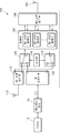
도 1은 본 발명의 기술적 사상에 의한 일 실시예에 따른 리모트 장치의 일부 구성을 개략적으로 나타내는 도면이다.
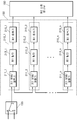
도 2는 도 1에 도시된 증폭부의 세부적인 구성을 도시하는 예시적인 도면이다.
도 3은 도 1에 도시된 증폭부의 세부적인 구성을 도시하는 예시적인 도면이다.
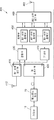
도 4는 본 발명의 기술적 사상에 의한 다른 실시예에 따른 리모트 장치의 일부 구성을 개략적으로 나타내는 도면이다.BRIEF DESCRIPTION OF THE DRAWINGS A brief description of each drawing is provided to more fully understand the drawings recited in the description of the invention.
BRIEF DESCRIPTION OF DRAWINGS FIG. 1 is a schematic view showing a part of a remote device according to an embodiment of the present invention; FIG.
2 is an exemplary diagram showing a detailed configuration of the amplification unit shown in Fig.
3 is an exemplary diagram showing a detailed configuration of the amplification unit shown in FIG.
4 is a view schematically showing a part of the configuration of a remote device according to another embodiment of the present invention.
본 발명은 다양한 변경을 가할 수 있고 여러 가지 실시예를 가질 수 있는 바, 특정 실시예들을 도면에 예시하고 이를 상세한 설명을 통해 상세히 설명하고자 한다. 그러나, 이는 본 발명을 특정한 실시 형태에 대해 한정하려는 것이 아니며, 본 발명의 사상 및 기술 범위에 포함되는 모든 변경, 균등물 내지 대체물을 포함하는 것으로 이해되어야 한다.While the present invention has been described in connection with certain exemplary embodiments, it is to be understood that the invention is not limited to the disclosed embodiments, but, on the contrary, is intended to cover various modifications and similarities. It should be understood, however, that the invention is not intended to be limited to the particular embodiments, but includes all modifications, equivalents, and alternatives falling within the spirit and scope of the invention.
본 발명을 설명함에 있어서, 관련된 공지 기술에 대한 구체적인 설명이 본 발명의 요지를 불필요하게 흐릴 수 있다고 판단되는 경우 그 상세한 설명을 생략한다. 또한, 본 명세서의 설명 과정에서 이용되는 숫자(예를 들어, 제1, 제2 등)는 하나의 구성요소를 다른 구성요소와 구분하기 위한 식별기호에 불과하다.DETAILED DESCRIPTION OF THE PREFERRED EMBODIMENTS In the following description of the present invention, detailed description of known related arts will be omitted when it is determined that the gist of the present invention may be unnecessarily obscured. In addition, numerals (e.g., first, second, etc.) used in the description of the present invention are merely an identifier for distinguishing one component from another.
또한, 본 명세서에서, 일 구성요소가 다른 구성요소와 "연결된다" 거나 "접속된다" 등으로 언급된 때에는, 상기 일 구성요소가 상기 다른 구성요소와 직접 연결되거나 또는 직접 접속될 수도 있지만, 특별히 반대되는 기재가 존재하지 않는 이상, 중간에 또 다른 구성요소를 매개하여 연결되거나 또는 접속될 수도 있다고 이해되어야 할 것이다.Also, in this specification, when an element is referred to as being "connected" or "connected" with another element, the element may be directly connected or directly connected to the other element, It should be understood that, unless an opposite description is present, it may be connected or connected via another element in the middle.
또한, 본 명세서에 기재된 "~부(유닛)", "~기", "~자", "~모듈" 등의 용어는 적어도 하나의 기능이나 동작을 처리하는 단위를 의미하며, 이는 하드웨어나 소프트웨어 또는 하드웨어 및 소프트웨어의 결합으로 구현될 수 있다.It should be noted that the terms such as " unit, "" to, "and" to module ", as used herein, mean units for processing at least one function or operation, Or a combination of hardware and software.
그리고 본 명세서에서의 구성부들에 대한 구분은 각 구성부가 담당하는 주기능 별로 구분한 것에 불과함을 명확히 하고자 한다. 즉, 이하에서 설명할 2개 이상의 구성부가 하나의 구성부로 합쳐지거나 또는 하나의 구성부가 보다 세분화된 기능별로 2개 이상으로 분화되어 구비될 수도 있다. 그리고 이하에서 설명할 구성부 각각은 자신이 담당하는 주기능 이외에도 다른 구성부가 담당하는 기능 중 일부 또는 전부의 기능을 추가적으로 수행할 수도 있으며, 구성부 각각이 담당하는 주기능 중 일부 기능이 다른 구성부에 의해 전담되어 수행될 수도 있음은 물론이다.It is to be clarified that the division of constituent parts in this specification is merely a division by each main function of each constituent part. That is, two or more constituent parts to be described below may be combined into one constituent part, or one constituent part may be divided into two or more functions according to functions that are more subdivided. In addition, each of the constituent units described below may additionally perform some or all of the functions of other constituent units in addition to the main functions of the constituent units themselves, and that some of the main functions, And may be carried out in a dedicated manner.
이하, 본 발명의 실시예들을 차례로 상세히 설명한다.
Hereinafter, embodiments of the present invention will be described in detail.
도 1은 본 발명의 기술적 사상에 의한 일 실시예에 따른 리모트 장치(100)의 일부 구성을 개략적으로 나타내는 도면이다. 도 1에서는, 리모트 장치(100)가 헤드엔드 장치(20)와 통신적으로 결합되어, 기지국(10)과 사용자 단말(도시 생략) 사이의 통신을 중계하는 분산 안테나 시스템을 구성하는 것으로 도시되고 있으나, 본 발명의 기술적 사상이 이에 한정되는 것은 아니다. 구현예에 따라서, 리모트 장치(100)는 헤드엔드 장치(20)와 통신적으로 결합되지 않고, 독자적으로 기지국(10), 다른 기지국, 기지국 릴레이 노드 장비 등과 사용자 단말 사이의 통신을 중계할 수 있음은 물론이다.1 is a diagram schematically showing a part of a configuration of a
도 1을 참조하면, 본 발명의 일 실시예에 따른 리모트 장치(100)는 제1 신호 분기부(110), 광 송수신부(120), 제1 스위치부(130), 제어부(140) 및 증폭부(150)를 포함할 수 있으며, 리모트 장치(100)는 제2 신호 분기부(160)를 더 포함할 수도 있다.Referring to FIG. 1, a
제1 신호 분기부(110)는 제1 다운링크 신호를 입력받을 수 있다. 제1 신호 분기부(110)는 기지국(10) 또는 다른 기지국 등으로부터 전송되는 제1 다운링크 신호를 제1 안테나(112)를 통해서 무선으로(wirelessly) 입력받을 수 있다. 제1 다운링크 신호는, 서로 다른 주파수 대역을 갖는 복수의 RF 신호를 포함하는 기지국 신호일 수 있다.The first
광 송수신부(120)는 다운링크 광 신호를 입력받을 수 있다. 광 송수신부(120)는 헤드엔드 장치(20)와 소정의 전송 매체, 예를 들면 광 케이블을 통해 연결될 수 있으며 헤드엔드 장치(20)로부터 다운링크 광 신호를 입력받을 수 있다. 여기서, 다운링크 광 신호는, 기지국(10)으로부터 전송되며 서로 다른 주파수 대역을 갖는 복수의 RF 신호를 포함하는 기지국 신호가 헤드엔드 장치(20)에 의해 전광 변환된 신호일 수 있다.The
광 송수신부(120)는 입력된 다운링크 광 신호를 제2 다운링크 신호로 변환할 수 있다. 여기서, 제2 다운링크 신호는, 다운링크 광 신호를 광전 변환하여 헤드엔드 장치(20)가 기지국(10)으로부터 수신한 기지국 신호로 복원한 신호일 수 있다. The optical transmitter /
제1 다운링크 신호와 제2 다운링크 신호에 포함된 복수의 RF 신호 각각은 서로 대응되는 주파수 대역을 가질 수 있으며, 어느 하나의 주파수 대역에 대응하는 제1 다운링크 신호의 RF 신호와 제2 다운링크 신호의 RF 신호는 동일한 채널을 이용하는 신호일 수 있다.Each of the plurality of RF signals included in the first downlink signal and the second downlink signal may have a frequency band corresponding to each other, and the RF signal of the first downlink signal corresponding to one of the frequency bands and the second down signal The RF signal of the link signal may be a signal using the same channel.
제1 스위치부(130)는 제1 신호 분기부(110)와 연결되는 제1 입력 단자(a) 및 광 송수신부(120)와 연결되는 제2 입력 단자(b)와, 출력 단자(c) 사이의 연결을 스위칭할 수 있다. 출력 단자(c)에는 증폭부(150)가 연결될 수 있다.The
제어부(140)는 제1 입력 단자(a) 또는 제2 입력 단자(b)가 출력 단자(c)에 연결되도록 제1 스위치부(130)를 제어할 수 있다. 제어부(140)는 제1 다운링크 신호를 증폭부(150)로 전달할지 또는 제2 다운링크 신호를 증폭부(150)로 전달할지 여부를 결정할 수 있으며, 결정된 바에 따라 제1 입력 단자(a) 또는 제2 입력 단자(b)를 출력 단자(c)에 연결시킬 수 있다.The
제어부(140)가 제1 다운링크 신호와 제2 다운링크 신호 중 어느 신호를 증폭부(150)를 전달할지는 다양한 방법으로 결정될 수 있다. 일부 실시예에서, 제어부(140)는 관리자의 입력에 응답하여 제1 다운링크 신호 또는 제2 다운링크 신호를 증폭부(150)로 전달할 수 있다. 다른 실시예에서, 제어부(140)는 관리 서버, 예를 들면 NMS(network management system) 서버로부터 전송되는 제어 신호에 응답하여, 제1 다운링크 신호 또는 제2 다운링크 신호를 증폭부(150)로 전달할 수 있다.Whether the
증폭부(150)는 출력 단자(c)로부터 출력되는 제1 다운링크 신호 또는 제2 다운링크 신호를 증폭할 수 있다. 도 1에 도시된 바와 같이, 증폭부(150)는 제1 다운링크 신호 또는 제2 다운링크 신호에 포함된 서로 다른 주파수 대역의 복수의 RF 신호들 중 대응하는 주파수 대역의 RF 신호를 증폭하는 복수의 서브 증폭부를 포함할 수 있다. 복수의 서브 증폭부는 캐스케이드(cascade) 구조로 연결될 수 있는데, 복수의 서브 증폭부의 세부적인 구성에 대해서는 도 2 및 도 3을 참조하여 후술한다.The amplifying
제2 신호 분기부(160)는 복수의 서브 증폭부 각각으로부터 출력되는 복수의 RF 신호를 결합할 수 있다. 제2 신호 분기부(160)는 결합된 복수의 RF 신호를 제2 안테나(162)를 통해 외부의 다른 장치, 예를 들어, 휴대폰, 태블릿 PC 등과 같은 사용자 단말로 전송할 수 있다.The second
한편, 도 1을 보면, 리모트 장치(100)는 제2 스위치부(170)를 더 포함할 수 있다. 제2 스위치부(170)는 업링크용 스위치로서, 도 1은 제1 스위치부(130)와 제2 스위치부(170)가 서로 분리된 것으로 도시되고 있지만, 구현예에 따라서는 제1 스위치부(130)와 제2 스위치부(170)가 하나의 모듈로 구성될 수도 있다.Referring to FIG. 1, the
제2 스위치부(170)의 입력 단자(c')는 증폭부(150)와 연결될 수 있고, 제2 스위치부(170)의 제 1 출력 단자(a')는 제1 신호 분기부(110)에, 제2 스위치부(170)의 제 2 출력 단자(b')는 광 송수신부(120)에 연결될 수 있다.The input terminal c 'of the
증폭부(150)는 서로 다른 주파수 대역을 갖는 복수의 RF 신호를 증폭하여 제2 스위치부(170)의 입력 단자(c')로 전달할 수 있다. 여기서, 상기 복수의 RF 신호는, 사용자 단말로부터 전송되는 업링크 신호가 제2 신호 분기부(160)에 의해 분리된 신호이며, 증폭부(150)는 증폭된 복수의 RF 신호를 결합하여 업링크 신호로 출력할 수 있다.The amplifying
제어부(140)는 제2 스위치부(170)의 입력 단자(c')가 제1 출력 단자(a') 또는 제2 출력 단자(b')에 연결되도록 제2 스위치부(170)를 제어하여 증폭부(150)로부터 출력되는 업링크 신호를 제1 신호 분기부(110) 또는 광 송수신부(120)로 전달할 수 있다.The
여기서, 제어부(140)는 제1 신호 분기부(110)와 광 송수신부(120) 중 제1 스위치부(130)를 통해 증폭부(150)와 연결된 구성이 제2 스위치부(170)를 통해 증폭부(150)와 연결될 수 있도록 제2 스위치부(170)를 제어할 수 있다. 예를 들어, 제1 스위치부(130)의 제1 입력 단자(a)와 출력 단자(c)가 연결되어 제1 신호 분기부(110)와 증폭부(150)가 연결된 경우, 제어부(140)는 제2 스위치부(170)의 입력 단자(c')와 제 1 출력 단자(a')를 연결시켜 제1 신호 분기부(110)와 증폭부(150)가 연결되도록 할 수 있다.The
본 발명의 일 실시예에 따른 리모트 장치(100)는 기지국(10) 또는 다른 기지국 등으로부터 직접 입력되는 신호와 헤드엔드 장치(20)로부터 입력되는 신호를 선택적으로 증폭하여 외부 장치로 전송할 수 있다. 이에 따라, 리모트 장치(100)는 헤드엔드 장치(20)의 오작동, 광 케이블의 장애 등의 이유로 정상적인 서비스의 제공이 어려운 경우에도 기지국(10) 등으로부터 직접 기지국 신호를 수신하여 사용자에게 서비스를 제공할 수 있다. 또한, 리모트 장치(100)는, 헤드엔드 장치(20)와 연결되어 분산 안테나 시스템을 구성하기 어려운 경우 등에는, 독자적인 중계기로 기능하여 사용자에게 서비스를 제공할 수도 있다.
The
도 2는 도 1에 도시된 증폭부(150)의 세부적인 구성을 도시하는 예시적인 도면이다.FIG. 2 is an exemplary diagram showing a detailed configuration of the
도 2를 참조하면, 서브 증폭부(210_1 내지 210_n) 각각은 제1 분배/결합기(211), 제1 필터(213) 및 제1 증폭기(215)를 포함할 수 있다. 서브 증폭부(210_1 내지 210_n)의 개수는 당업자에 의해 자명하게 변경될 수 있다.Referring to FIG. 2, each of the sub amplifying units 210_1 to 210 - n may include a first distributor / combiner 211, a first filter 213, and a first amplifier 215. The number of the sub-amplification units 210_1 to 210_n can be changed by persons skilled in the art.
제1 분배/결합기들(211_1 내지 211_n)은, 제1 다운링크 신호, 제2 다운링크 신호 및 전단에 연결된 서브 증폭부로부터 입력되는 신호 중 어느 하나를 분할하여 후단에 연결된 서브 증폭부로 전달할 수 있다. 제1 서브 증폭부(210_1)의 제1 분배/결합기(211_1)는 입력되는 신호를 분할하여 제2 서브 증폭부(210_2)의 제1 분배/결합기(211_2)로 전달하고, 제2 서브 증폭부(210_2)의 제1 분배/결합기(211_2)는 제1 서브 증폭부(210_1)의 제1 분배/결합기(211_1)로부터 전달된 신호를 제3 서브 증폭부의 제1 분배/결합기(도시 생략)로 전달할 수 있다. 제1 분배/결합기들(211_1 내지 211_n)이 각기 후단에 연결되는 서브 증폭부의 제1 분배/결합기로 전송하는 신호는 모두 제1 다운링크 신호 또는 제2 다운링크 신호에 포함된 서로 다른 주파수 대역의 복수의 RF 신호를 포함할 수 있다. The first distribution / combiners 211_1 through 211_n may divide any one of the first downlink signal, the second downlink signal, and the signal input from the sub-amplification unit connected to the previous stage and transmit the divided signal to the sub-amplification unit connected to the subsequent stage . The first distributor / combiner 211_1 of the first sub-amplifier 210_1 divides the input signal and transmits the divided signal to the first distributor / combiner 211_2 of the second sub-amplifier 210_2, The first distributor / combiner 211_2 of the first sub-amplifier 210_1 and the first distributor / combiner 211_2 of the second sub-amplifier 210_1 direct the signal delivered from the first distributor / combiner 211_1 of the first sub- . The signals transmitted to the first distributing / combiners of the sub-amplifiers connected to the subsequent stages of the first distributing / combiners 211_1 through 211_n are all signals of different frequency bands included in the first downlink signal or the second downlink signal And may include a plurality of RF signals.
한편, 도 2에 도시되지는 않았으나, 제1 분배/결합기들(211_1 내지 211_n)은 증폭기를 포함할 수 있으며, 상기 증폭기를 이용하여 제1 다운링크 신호 또는 제2 다운링크 신호의 분할에 따른 손실을 보상할 수 있다. 구현예에 따라서는, 상기 증폭기는 제1 분배/결합기들(211_1 내지 211_n) 중 대응하는 제1 분배/결합기와 별개의 모듈로 구현될 수도 있다.2, the first distribution / combiners 211_1 through 211_n may include an amplifier, and the amplifier may be used to reduce the loss due to the division of the first downlink signal or the second downlink signal Can be compensated. Depending on the implementation, the amplifier may be implemented as a separate module from the corresponding first distributor / combiner of the first distributor / combiners 211_1 through 211_n.
제1 필터들(213_1 내지 213_n)은 복수의 주파수 대역 중 대응하는 주파수 대역의 RF 신호를 통과시킬 수 있다. 제1 필터들(213_1 내지 213_n)은 서로 다른 필터링 주파수를 가질 수 있다. 즉, 제1 서브 증폭부(210_1)의 제1 필터(213_1)를 통과한 RF 신호와, 제2 서브 증폭부(210_2)의 제2 필터(213_2)를 통과한 RF 신호는 서로 다른 대역폭을 가질 수 있다.The first filters 213_1 to 213_n can pass RF signals of corresponding frequency bands among a plurality of frequency bands. The first filters 213_1 to 213_n may have different filtering frequencies. That is, the RF signal having passed through the first filter 213_1 of the first sub-amplification unit 210_1 and the RF signal having passed through the second filter 213_2 of the second sub-amplification unit 210_2 have different bandwidths .
제1 증폭기들(215_1 내지 215_n)은 대응하는 제1 필터를 통과한 RF 신호를 증폭할 수 있다. 제1 증폭기들(215_1 내지 215_n)은 고출력 증폭기일 수 있다. 제1 증폭기들(215_1 내지 215_n)은 증폭된 RF 신호를 제2 신호 분기부(160)로 전달할 수 있다. The first amplifiers 215_1 through 215_n may amplify the RF signal that has passed through the corresponding first filter. The first amplifiers 215_1 to 215_n may be high-power amplifiers. The first amplifiers 215_1 to 215_n may transmit the amplified RF signal to the second
도 2에 도시되지는 않았지만, 각 서브 증폭부(210_1 내지 210_n)는 제1 다운링크 신호, 제2 다운링크 신호 및 전단에 연결된 서브 증폭부로부터 입력되는 신호를 증폭하여 대응하는 제1 분배/결합기로 전달하는 증폭기를 더 포함할 수 있다. 이 때, 상기 증폭기는 저잡음 증폭기일 수 있다.
Although not shown in FIG. 2, each of the sub amplifying units 210_1 to 210 - n amplifies a signal input from a first downlink signal, a second downlink signal, and a sub-amplifying unit connected to the preceding stage, As shown in FIG. At this time, the amplifier may be a low noise amplifier.
도 3은 도 1에 도시된 증폭부(150)의 세부적인 구성을 도시하는 예시적인 도면이다.3 is an exemplary diagram showing a detailed configuration of the amplifying
도 3에 도시된 서브 증폭부들(210_1 내지 210_n)은 도 2에 도시된 서브 증폭부들(210_1 내지 210_n)에 비해, 제2 필터(212), 제2 분배/결합기(214) 및 제2 증폭기(216)를 더 포함할 수 있다.The sub-amplification units 210_1 to 210_n shown in FIG. 3 are different from the sub-amplification units 210_1 to 210_n shown in FIG. 2 in that the second filter 212, the second distributor / combiner 214, 216).
제2 필터들(212_1 내지 212_n)은 업링크 신호에 포함된 복수의 주파수 대역의 RF 신호들 중 대응하는 주파수 대역의 RF 신호를 입력받을 수 있다. 여기서, 상기 복수의 RF 신호는 제2 신호 분기부(160)가 사용자 단말(도시 생략)로부터 전송되는 업링크 신호를 필터링을 통해 주파수 대역 별로 분리하여 생성한 신호일 수 있다. 제2 필터들(212_1 내지 212_n)은 각각 입력되는 RF 신호에 포함된 잡음을 제거할 수 있다.The second filters 212_1 to 212_n may receive RF signals of corresponding frequency bands among RF signals of a plurality of frequency bands included in the uplink signal. Here, the plurality of RF signals may be signals generated by separating the uplink signals transmitted from the user terminal (not shown) by the second
한편, 구현예에 따라서는, 제2 필터들(212_1 내지 212_n)은 모두 동일한 업링크 신호를 입력받을 수도 있다. 즉, 제2 필터들(212_1 내지 212_n)은, 서로 다른 주파수 대역의 복수의 RF 신호들을 포함하는 업링크 신호를 입력받을 수 있고, 입력되는 업링크 신호를 필터링하여 기설정된 주파수 대역의 RF 신호를 통과시켜 출력할 수 있으며, 이 경우, 제2 신호 분기부(160)는 사용자 단말로부터 입력되는 업링크 신호를 분할하여 각 서브 증폭부(210_1 내지 210_n)에 포함된 제2 필터들로 전달할 수 있다.On the other hand, according to the embodiment, the second filters 212_1 to 212_n may all receive the same uplink signal. That is, the second filters 212_1 to 212_n can receive uplink signals including a plurality of RF signals of different frequency bands, filter the input uplink signals, and output RF signals of a predetermined frequency band In this case, the second
제2 분배/결합기들(214_1 내지 214_n)은 제2 ?터들(212_1 내지 212_n) 중 대응하는 제2 필터로부터 출력되는 RF 신호와 전단에 연결된 서브 증폭부, 구체적으로, 전단에 연결된 서브 증폭부의 제2 증폭기로부터 전달되는 신호를 결합하여 출력할 수 있다. 제1 서브 증폭부(210_1)의 제2 분배/결합기(214_1)는 전단에 연결된 서브 증폭부가 존재하지 않으므로, 제2 필터(212_1)로부터 출력되는 RF 신호만을 제2 증폭기(216_1)로 전달할 것이다. 제2 서브 증폭부(210_2)의 제2 분배/결합기(214_2)는 전단에 연결된 제1 서브 증폭부(210_1)의 제2 증폭기(216_1)로부터 출력되는 신호와 제2 필터(212_2)로부터 출력되는 RF 신호를 결합하여 제2 증폭기(216_1)로 전달할 것이다. 또한, 제n 서브 증폭부(210_n)의 제2 분배/결합기(214_n)는 전단에 연결된 제n-1 서브 증폭부로부터 전달되는 신호와 제2 필터(212_n)로부터 출력되는 RF 신호를 결합하여 제2 증폭기(216_n)로 전달할 것이다. 이에 따라 최후단의 서브 증폭부인 제n 서브 증폭부(210_n)에서는, 사용자 단말로부터 전송된 업링크 신호에 포함된 모든 주파수 복수의 RF 신호들이 결합될 수 있다.The second distribution / combiners 214_1 to 214_n are connected to the sub-amplification unit connected to the front end of the RF signal output from the corresponding second filter among the second IDTs 212_1 to 212_n, 2 amplifiers can be combined and output. Since the second distributor / combiner 214_1 of the first sub-amplifier 210_1 does not have a sub-amplifier connected to the previous stage, only the RF signal output from the second filter 212_1 will be transmitted to the second amplifier 216_1. The second distributor / combiner 214_2 of the second sub-amplifier 210_2 receives the signal output from the second amplifier 216_1 of the first sub-amplifier 210_1 connected to the previous stage and the signal output from the second filter 212_2 RF signal to the second amplifier 216_1. The second distributor / combiner 214_n of the nth sub-amplifying unit 210_n combines the signal transmitted from the (n-1) th sub-amplifier connected to the previous stage and the RF signal output from the second filter 212_n, 2 amplifier 216_n. Accordingly, in the n-th sub-amplification unit 210_n, which is the last sub-amplification unit, all the RF signals of all the frequencies included in the uplink signal transmitted from the user terminal can be combined.
한편, 도 3에 도시되지는 않았으나, 제2 분배/결합기들(214_1 내지 214_n)은 증폭기를 포함할 수 있으며, 상기 증폭기를 이용하여 전단에 연결된 서브 증폭부로부터 전달되는 신호와 대응하는 제2 필터로부터 전달되는 신호의 결합에 따른 손실을 보상할 수 있다. 또한, 제2 분배/결합기들(214_1 내지 214_n)은 감쇠기를 포함할 수 있으며, 상기 감쇠기를 이용하여 전단에 연결된 서브 증폭부로부터 전달되는 신호의 이득을 조절할 수 있다. 구현예에 따라서는, 상기 증폭기 및/또는 상기 감쇠기는 제2 분배/결합기들(214_1 내지 214_n) 중 대응하는 제2 분배/결합기와 별개의 모듈로 구현될 수도 있다.3, the second distribution / combiners 214_1 through 214_n may include an amplifier, and a second filter corresponding to a signal transmitted from the sub-amplifier connected to the previous stage using the amplifier, It is possible to compensate for the loss due to the combination of the signals transmitted from the antenna. In addition, the second distribution / combiners 214_1 through 214_n may include an attenuator, and the attenuator may be used to adjust the gain of a signal transmitted from the sub-amplifier connected to the previous stage. Depending on the implementation, the amplifier and / or the attenuator may be implemented as a separate module from the corresponding second distributor / combiner of the second distributor / combiners 214_1 through 214_n.
제2 증폭기들(216_1 내지 216_n)은 제2 분배/결합기들(214_1 내지 214_n) 중 대응하는 제2 분배/결합기로부터 출력되는 RF 신호를 증폭할 수 있다. 제2 증폭기들(216_1 내지 216_n)은 고출력 증폭기일 수 있다. 제2 증폭기들(216_1 내지 216_n-1)은 증폭된 RF 신호를 후단에 연결된 서브 증폭부로 전달할 수 있고, 제2 증폭기(216_n)는 증폭된 RF 신호를 제2 스위치부(170)의 입력 단자(c')로 전달할 수 있다. 제1 서브 증폭부(210_1)의 제2 증폭기(216_1)는 증폭된 RF 신호를 제2 서브 증폭부(210_2)의 제2 분배/결합기(214_2)로 전달할 것이다. 제2 서브 증폭부(210_2)의 제2 증폭기(216_2)는 증폭된 RF 신호를 후단에 연결된 서브 증폭부의 제2 분배/결합기로 전달할 것이다. 이와 같이 전단의 서브 증폭부에 의해 증폭된 신호들이 순차적으로 후단의 서브 증폭부에서 결합된 후 최후단에 연결된 제n 서브 증폭부(210_n)까지 전달됨에 따라, 제n 서브 증폭부(210_n)는 제2 분배/결합기(214_n)로부터 출력되는 RF 신호를 증폭하여 업링크 신호로 복원할 수 있고 복원된 업링크 신호를 제2 스위치부(170)의 입력 단자(c')로 전달할 수 있다.The second amplifiers 216_1 through 216_n may amplify RF signals output from the corresponding second distributor / combiner of the second distributor / combiners 214_1 through 214_n. The second amplifiers 216_1 through 216_n may be high-power amplifiers. The second amplifiers 216_1 to 216_n-1 may transmit the amplified RF signal to the sub-amplification unit connected to the subsequent stage, and the second amplifier 216_n may amplify the amplified RF signal to the input terminal of the second switch unit 170 c '). The second amplifier 216_1 of the first sub-amplifier 210_1 may deliver the amplified RF signal to the second distributor / combiner 214_2 of the second sub-amplifier 210_2. The second amplifier 216_2 of the second sub-amplifier 210_2 will deliver the amplified RF signal to the second distributor / combiner of the sub-amplifier connected to the subsequent stage. In this manner, the signals amplified by the sub-amplifying units of the previous stage are sequentially coupled to the n-th sub-amplifying unit 210_n connected to the rearmost sub-amplifying unit, It is possible to amplify the RF signal output from the second distributor / combiner 214_n and restore it to the uplink signal, and to transfer the restored uplink signal to the input terminal c 'of the
한편, 도 3에는 도시되지 않았지만, 각 서브 증폭부(210_1 내지 210_n)는 제2 신호 분기부(160)로부터 입력되는 RF 신호를 증폭하여 대응하는 제2 필터로 전달하는 증폭기를 더 포함할 수 있다. 이 때, 상기 증폭기는 저잡음 증폭기일 수 있다.
Although not shown in FIG. 3, each of the sub amplifying units 210_1 to 210 - n may further include an amplifier that amplifies the RF signal input from the second
도 4는 본 발명의 기술적 사상에 의한 다른 실시예에 따른 리모트 장치(400)의 일부 구성을 개략적으로 나타내는 도면이다. 도 4를 설명함에 있어서, 도 1에서와 동일한 참조부호는 동일한 구성을 나타내므로, 설명의 간략화를 위해 중복되는 설명은 생략하고 차이점 위주로 설명한다.4 is a view schematically showing a part of a configuration of a
도 4를 참조하면, 본 발명의 다른 실시예에 따른 리모트 장치(400)는 제1 신호 분기부(410), 광 송수신부(420), 결합부(430) 및 증폭부(450)를 포함할 수 있으며, 리모트 장치(400)는 제2 신호 분기부(460) 및 분배부(470)를 더 포함할 수 있다.4, a
제1 신호 분기부(410)는 제1 다운링크 신호를 입력받을 수 있다. 제1 신호 분기부(410)는 기지국(10) 또는 다른 기지국 등으로부터 전송되는 제1 다운링크 신호를 제1 안테나(412)를 통해서 무선으로(wirelessly) 입력받을 수 있다. 제1 다운링크 신호는, 서로 다른 주파수 대역을 갖는 복수의 RF 신호를 포함하는 기지국 신호일 수 있다. The first
광 송수신부(420)는 다운링크 광 신호를 입력받을 수 있다. 광 송수신부(420)는 헤드엔드 장치(20)와 소정의 전송 매체, 예를 들면 광 케이블을 통해 연결될 수 있으며 헤드엔드 장치(20)로부터 다운링크 광 신호를 입력받을 수 있다. 여기서, 다운링크 광 신호는, 기지국(10)으로부터 전송되며 서로 다른 주파수 대역을 갖는 복수의 RF 신호를 포함하는 기지국 신호가 헤드엔드 장치(20)에 의해 전광 변환된 신호일 수 있다. The
광 송수신부(420)는 입력된 다운링크 광 신호를 제2 다운링크 신호로 변환할 수 있다. 여기서, 제2 다운링크 신호는, 다운링크 광 신호를 광전 변환하여 헤드엔드 장치(20)가 기지국(10)으로부터 수신한 기지국 신호로 복원한 신호일 수 있다. The
제1 다운링크 신호와 제2 다운링크 신호에 포함된 복수의 RF 신호 각각은 서로 대응되는 주파수 대역을 가질 수 있으며, 어느 하나의 주파수 대역에 대응하는 제1 다운링크 신호의 RF 신호와 제2 다운링크 신호의 RF 신호는 서로 다른 채널을 이용하는 신호일 수 있다. 예를 들어, 30MHz 내지 50MHz의 주파수 대역에 대응하는 제1 다운링크 신호의 RF 신호와 제2 다운링크 신호의 RF 신호가 존재하는 경우, 제1 다운링크 신호에 포함된 RF 신호는 30MHz 내지 35MHz의 채널을 이용할 수 있고, 제2 다운링크 신호에 포함된 RF 신호는 35MHz 내지 40MHz의 채널을 이용할 수 있다.Each of the plurality of RF signals included in the first downlink signal and the second downlink signal may have a frequency band corresponding to each other, and the RF signal of the first downlink signal corresponding to one of the frequency bands and the second down signal The RF signal of the link signal may be a signal using a different channel. For example, when there is an RF signal of the first downlink signal and an RF signal of the second downlink signal corresponding to the frequency band of 30 MHz to 50 MHz, the RF signal included in the first downlink signal is in the range of 30 MHz to 35 MHz Channel, and the RF signal included in the second downlink signal may use a channel of 35 MHz to 40 MHz.
결합부(430)는 제1 다운링크 신호와 제2 다운링크 신호를 결합하여 제3 다운링크 신호를 생성할 수 있고 생성된 제3 다운링크 신호를 증폭부(450)로 전달할 수 있다.The combining
증폭부(450)는 결합부(430)로부터 출력되는 제3 다운링크 신호를 증폭할 수 있다. 도 4에 도시된 바와 같이, 증폭부(450)는 제3 다운링크 신호에 포함된 서로 다른 주파수 대역의 복수의 RF 신호들 중 대응하는 주파수 대역의 RF 신호를 증폭하는 복수의 서브 증폭부를 포함할 수 있다. The amplifying
복수의 서브 증폭부는 도 2 및 도 3에 도시된 복수의 서브 증폭부(210_1 내지 210_n)와 동일한 구성을 가질 수 있으며, 단지 도 2 및 도 3에 도시된 제1 스위치부(130)는 결합부(430)로 변경되고, 제2 스위치부(170)는 분배부(470)로 변경된다.The plurality of sub-amplifying units may have the same configuration as that of the plurality of sub-amplifying units 210_1 to 210_n shown in FIGS. 2 and 3. The
복수의 서브 증폭부 중 어느 하나의 서브 증폭부가 증폭하는 RF 신호는, 어느 하나의 서브 증폭부의 제1 필터를 통과한 제1 다운링크 신호의 RF 신호와 제2 다운링크 신호의 RF 신호를 포함할 것이다.The RF signal amplified by one of the plurality of sub-amplification units includes the RF signal of the first downlink signal and the RF signal of the second downlink signal which have passed through the first filter of any one of the sub-amplification units will be.
제2 신호 분기부(460)는 복수의 서브 증폭부 각각에 의해 증폭된 복수의 RF 신호를 결합할 수 있다. 제2 신호 분기부(460)는 결합된 복수의 RF 신호를 제2 안테나(462)를 통해 외부의 다른 장치, 예를 들어, 휴대폰, 태블릿 PC 등과 같은 사용자 단말로 전송할 수 있다.The second
한편, 증폭부(450)는 제2 신호 분기부(460)로부터 분리되어 입력되는 RF 신호들을 증폭하여 사용자 단말로부터 전송되는 업링크 신호를 복원할 수 있고, 복원된 업링크 신호를 분배부(470)로 전달할 수 있다. The
분배부(470)는 업링크 신호에 포함된 복수의 RF 신호를 주파수 대역 및 채널 별로 분리하여 제1 신호 분기부(410) 및 광 송수신부(420)로 전달할 수 있다. 결합부(430)가 제1 신호 분기부(410)로부터 제1 주파수 대역의 제1 채널 신호, 제2 주파수 대역의 제1 채널 신호 및 제3 주파수 대역의 제1 채널 신호를 수신하고, 광 송수신부(420)로부터 제1 주파수 대역의 제2 채널 신호, 제2 주파수 대역의 제2 채널 신호 및 제3 주파수 대역의 제2 채널 신호를 수신한 경우, 분배부(470)는 증폭부(450)로부터 전달되는 업링크 신호 중 제1 주파수 대역의 제1 채널 신호, 제2 주파수 대역의 제1 채널 신호 및 제3 주파수 대역의 제1 채널 신호를 제1 신호 분기부(410)로 전달할 수 있고, 제1 주파수 대역의 제2 채널 신호, 제2 주파수 대역의 제2 채널 신호 및 제3 주파수 대역의 제2 채널 신호는 광 송수신부(420)로 전달할 수 있다. 즉, 분배부(470)는 특정 채널에 대응하는 신호에 대해서는 해당 채널의 신호를 입력받은 구성(제1 신호 분기부(410) 또는 광 송수신부(420))으로 전달하는 것이다.The
리모트 장치(400)는 헤드엔드 장치(20)로부터 입력되는 신호와 기지국(10) 또는 다른 기지국 등으로부터 직접 입력되는 신호를 함께 처리하여 외부 장치로 전송할 수 있다. 이에 따라, 리모트 장치(400)는 헤드엔드 장치(20)로부터 전송되는 신호를 기초로 정상적인 서비스를 제공하기 어려운 상황에서도 기지국(10) 또는 다른 기지국으로부터 직접 입력되는 신호를 기초로 사용자에게 서비스를 제공할 수 있어 서비스 신뢰성 및 품질을 보장할 수 있다. 또한, 리모트 장치(400)는, 독자적인 중계기로 기능하여 사용자에게 서비스를 제공할 수도 있다.
The
이상, 본 발명을 바람직한 실시예를 들어 상세하게 설명하였으나, 본 발명은 상기 실시예에 한정되지 않고, 본 발명의 기술적 사상 및 범위 내에서 당 분야에서 통상의 지식을 가진 자에 의하여 여러가지 변형 및 변경이 가능하다.
While the present invention has been particularly shown and described with reference to exemplary embodiments thereof, it is to be understood that the invention is not limited to the disclosed exemplary embodiments, but, on the contrary, This is possible.
100, 400: 리모트 장치
110, 410: 제1 신호 분기부
120, 420: 광 송수신부
130, 170: 제1 스위치부, 제2 스위치부
140: 제어부
150: 증폭부
160, 460: 제2 신호 분기부
430: 결합부
470: 분배부100, 400: Remote device
110, 410: first signal branching section
120, 420: Optical Transmission /
130, 170: a first switch unit, a second switch unit
140:
150:
160, 460: a second signal branching section
430:
470:
Claims (19)
다운링크 광 신호를 입력받고, 상기 다운링크 광 신호를 제2 다운링크 신호로 변환하는 광 송수신부;
상기 제1 신호 분기부와 연결되는 제1 입력 단자 및 상기 광 송수신부와 연결되는 제2 입력 단자와, 출력 단자 사이의 연결을 스위칭하는 제1 스위치부;
상기 제1 입력 단자 또는 상기 제2 입력 단자가 상기 출력 단자에 연결되도록 상기 제1 스위치부를 제어하는 제어부; 및
상기 출력 단자로부터 출력되는 상기 제1 다운링크 신호 또는 상기 제2 다운링크 신호를 증폭하는 증폭부;
를 포함하는 리모트 장치.
A first signal branching unit receiving a first downlink signal;
An optical transceiver receiving a downlink optical signal and converting the downlink optical signal into a second downlink signal;
A first switch unit for switching a connection between an output terminal and a first input terminal connected to the first signal branching unit, a second input terminal connected to the optical transceiver unit,
A control unit for controlling the first switch unit such that the first input terminal or the second input terminal is connected to the output terminal; And
An amplifier for amplifying the first downlink signal or the second downlink signal output from the output terminal;
.
상기 제1 신호 분기부는,
기지국으로부터 전송되는 상기 제1 다운링크 신호를 입력받고,
상기 광 송수신부는,
통신적으로 결합된(communicatively coupled) 헤드엔드 장치로부터 상기 다운링크 광 신호를 입력받고, 상기 다운링크 광 신호를 상기 제2 다운링크 신호로 변환하는, 리모트 장치.
The method according to claim 1,
Wherein the first signal branching unit comprises:
Receiving the first downlink signal transmitted from the base station,
The optical transmitter-
Receiving the downlink optical signal from a communicatively coupled head end device and converting the downlink optical signal into the second downlink signal.
상기 제1 다운링크 신호는,
상기 제2 다운링크 신호에 포함된 복수의 RF(Radio Frequency) 신호들 각각의 주파수 대역과 대응하는 주파수 대역을 갖되 상기 제2 다운링크 신호에 포함된 복수의 RF 신호들 각각의 채널과 동일한 채널을 이용하는 복수의 RF 신호들을 포함하는, 리모트 장치.
The method according to claim 1,
Wherein the first downlink signal comprises:
The second downlink signal having a frequency band corresponding to a frequency band of each of a plurality of RF signals included in the second downlink signal and having the same channel as each of the plurality of RF signals included in the second downlink signal, And a plurality of RF signals for use.
상기 증폭부는,
상기 제1 다운링크 신호 또는 상기 제2 다운링크 신호에 포함된 서로 다른 주파수 대역의 복수의 RF 신호들 중 대응하는 주파수 대역의 RF 신호를 증폭하는 복수의 서브 증폭부;를 포함하는, 리모트 장치.
The method according to claim 1,
Wherein,
And a plurality of sub-amplifiers for amplifying an RF signal of a corresponding frequency band among a plurality of RF signals of different frequency bands included in the first downlink signal or the second downlink signal.
상기 복수의 서브 증폭부는,
서로 캐스케이드 구조로 연결되는, 리모트 장치.
5. The method of claim 4,
Wherein the plurality of sub-
A remote device, cascaded to each other.
상기 복수의 서브 증폭부 중 적어도 하나는,
상기 제1 다운링크 신호 또는 상기 제2 다운링크 신호를 분할하여 후단에 연결된 서브 증폭부로 전달하는 제1 분배/결합기;
상기 제1 분배/결합기로부터 전달되는 상기 제1 다운링크 신호 또는 상기 제2 다운링크 신호를 필터링하여 대응하는 주파수 대역의 RF 신호를 출력하는 제1 필터; 및
상기 제1 필터로부터 출력되는 RF 신호를 증폭하는 제1 증폭기;를 포함하는, 리모트 장치.
5. The method of claim 4,
Wherein at least one of the plurality of sub-
A first distributor / combiner for dividing the first downlink signal or the second downlink signal and transmitting the divided downlink signal to a sub-amplification unit connected to a subsequent stage;
A first filter for filtering the first downlink signal or the second downlink signal transmitted from the first distributor / combiner and outputting an RF signal of a corresponding frequency band; And
And a first amplifier for amplifying the RF signal output from the first filter.
상기 리모트 장치는,
상기 복수의 서브 증폭부 각각에 의해 증폭된 복수의 RF 신호를 결합하는 제2 신호 분기부;를 더 포함하는, 리모트 장치.
5. The method of claim 4,
The remote device includes:
And a second signal branching unit for combining the plurality of RF signals amplified by each of the plurality of sub-amplifying units.
상기 리모트 장치는,
상기 증폭부와 연결되는 입력 단자와, 상기 제1 신호 분기부와 연결되는 제1 출력 단자 및 상기 광 송수신부와 연결되는 제2 출력 단자 사이의 연결을 스위칭하는 제2 스위치부; 및
입력되는 업링크 신호를 서로 다른 대역의 복수의 RF 신호들로 분리하는 제2 신호 분기부;를 더 포함하되,
상기 증폭부는,
상기 제2 신호 분기부로부터 출력되는 상기 복수의 RF 신호들을 증폭하고,
상기 제어부는,
상기 제2 스위치부의 입력 단자가 상기 제1 출력 단자 또는 상기 제2 출력 단자에 연결되도록 상기 제2 스위치부를 제어하는, 리모트 장치.
The method according to claim 1,
The remote device includes:
A second switch unit for switching a connection between an input terminal connected to the amplifying unit, a first output terminal connected to the first signal branching unit, and a second output terminal connected to the optical transmitting / receiving unit; And
And a second signal branching section for separating the input uplink signal into a plurality of RF signals of different bands,
Wherein,
Amplifying the plurality of RF signals output from the second signal branching unit,
Wherein,
And controls the second switch unit such that an input terminal of the second switch unit is connected to the first output terminal or the second output terminal.
상기 제어부는,
상기 제1 신호 분기부와 상기 광 송수신부 중 상기 제1 스위치부를 통해 상기 증폭부와 연결되는 구성이 상기 제2 스위치부를 통해 상기 증폭부와 연결되도록 상기 제2 스위치부를 제어하는, 리모트 장치.
9. The method of claim 8,
Wherein,
And controls the second switch unit such that a configuration of the first signal branching unit and the optical transceiver unit connected to the amplifying unit through the first switch unit is connected to the amplifying unit through the second switch unit.
상기 증폭부는,
입력되는 상기 복수의 RF 신호들 중 대응하는 주파수 대역의 RF 신호를 증폭하는 복수의 서브 증폭부;를 포함하는, 리모트 장치.
The method of claim 8, wherein
Wherein,
And a plurality of sub-amplifiers for amplifying an RF signal of a corresponding frequency band among the plurality of input RF signals.
상기 복수의 서브 증폭부 중 적어도 하나는,
입력되는 RF 신호의 노이즈를 제거하여 출력하는 제2 필터;
상기 제2 ?터로부터 출력되는 RF 신호와 전단에 연결된 서브 증폭부로부터 전달되는 RF 신호를 결합하는 제2 분배/결합기; 및
상기 제2 분배/결합기로부터 출력되는 결합된 RF 신호를 증폭하는 제2 증폭기;
를 포함하는, 리모트 장치.
11. The method of claim 10,
Wherein at least one of the plurality of sub-
A second filter for removing noise of an input RF signal and outputting the noise;
A second distributor / combiner for combining an RF signal output from the second detector and an RF signal transmitted from a sub-amplifier connected to a previous stage; And
A second amplifier for amplifying a combined RF signal output from the second distributor / combiner;
And a remote device.
상기 제어부는,
관리자의 입력 또는 관리 서버로부터 전송되는 제어 신호에 응답하여, 상기 제1 입력 단자 또는 상기 제2 입력 단자가 상기 출력 단자에 연결되도록 상기 제1 스위치부를 제어하는, 리모트 장치.
The method according to claim 1,
Wherein,
And controls the first switch unit such that the first input terminal or the second input terminal is connected to the output terminal in response to a manager input or a control signal transmitted from the management server.
다운링크 광 신호를 입력받고, 상기 다운링크 광 신호를 제2 다운링크 신호로 변환하는 광 송수신부;
상기 제1 및 제2 다운링크 신호를 입력받고, 상기 제1 및 제2 다운링크 신호를 결합하여 제3 다운링크 신호를 생성하는 결합부; 및
상기 제3 다운링크 신호를 입력받고, 상기 제3 다운링크 신호를 증폭하는 증폭부;
를 포함하는 리모트 장치.
A first signal branching unit receiving a first downlink signal;
An optical transceiver receiving a downlink optical signal and converting the downlink optical signal into a second downlink signal;
A combining unit for receiving the first and second downlink signals and combining the first and second downlink signals to generate a third downlink signal; And
An amplifying unit receiving the third downlink signal and amplifying the third downlink signal;
.
상기 제1 신호 분기부는,
기지국으로부터 전송되는 상기 제1 다운링크 신호를 입력받고,
상기 광 송수신부는,
통신적으로 결합된 헤드엔드 장치로부터 상기 다운링크 광 신호를 입력받고, 상기 다운링크 광 신호를 상기 제2 다운링크 신호로 변환하는, 리모트 장치.
14. The method of claim 13,
Wherein the first signal branching unit comprises:
Receiving the first downlink signal transmitted from the base station,
The optical transmitter-
Receives the downlink optical signal from a communicatively coupled head end apparatus and converts the downlink optical signal into the second downlink signal.
상기 제1 다운링크 신호는,
상기 제2 다운링크 신호에 포함된 복수의 RF 신호들 각각의 주파수 대역과 대응하는 주파수 대역을 갖되 상기 제2 다운링크 신호에 포함된 복수의 RF 신호들 각각의 채널과 다른 채널을 이용하는 복수의 RF 신호들을 포함하는, 리모트 장치.
14. The method of claim 13,
Wherein the first downlink signal comprises:
A plurality of RF signals having a frequency band corresponding to a frequency band of each of a plurality of RF signals included in the second downlink signal and using a channel different from the channel of each of the plurality of RF signals included in the second downlink signal, ≪ / RTI >
상기 증폭부는,
상기 제3 다운링크 신호에 포함된 서로 다른 주파수 대역의 복수의 RF 신호들 중 대응하는 주파수 대역의 RF 신호를 증폭하는 복수의 서브 증폭부;를 포함하는, 리모트 장치.
14. The method of claim 13,
Wherein,
And a plurality of sub-amplifiers for amplifying an RF signal of a corresponding frequency band among a plurality of RF signals of different frequency bands included in the third downlink signal.
상기 리모트 장치는,
상기 복수의 서브 증폭부 각각에 의해 증폭된 복수의 RF 신호를 결합하는 제2 신호 분기부;를 더 포함하는, 리모트 장치.
17. The method of claim 16,
The remote device includes:
And a second signal branching unit for combining the plurality of RF signals amplified by each of the plurality of sub-amplifying units.
상기 리모트 장치는,
입력되는 업링크 신호를 서로 다른 대역의 복수의 RF 신호들로 분리하는 제2 신호 분기부;를 더 포함하되,
상기 증폭부는,
상기 제2 신호 분기부로부터 출력되는 상기 복수의 RF 신호들을 증폭하고, 증폭된 RF 신호들을 결합하여 업링크 신호로 출력하는, 리모트 장치.
14. The method of claim 13,
The remote device includes:
And a second signal branching section for separating the input uplink signal into a plurality of RF signals of different bands,
Wherein,
Amplifies the plurality of RF signals output from the second signal branching section, and combines the amplified RF signals to output as an uplink signal.
상기 리모트 장치는,
상기 증폭부로부터 출력되는 업링크 신호를 입력받고, 상기 업링크 신호를 제1 업링크 신호와 제2 업링크 신호로 분리하고, 상기 제1 업링크 신호를 상기 제1 신호 분기부로 전달하고 상기 제2 업링크 신호를 상기 광 송수신부로 전달하는 분배부;를 더 포함하는, 리모트 장치.
19. The method of claim 18,
The remote device includes:
And an uplink signal output section for separating the uplink signal into a first uplink signal and a second uplink signal and transmitting the first uplink signal to the first signal branching section, 2 transmitting the uplink signal to the optical transmitting / receiving unit.
Priority Applications (1)
| Application Number | Priority Date | Filing Date | Title |
|---|---|---|---|
| KR1020140186412A KR101877266B1 (en) | 2014-12-22 | 2014-12-22 | Remote apparatus of distributed antenna system |
Applications Claiming Priority (1)
| Application Number | Priority Date | Filing Date | Title |
|---|---|---|---|
| KR1020140186412A KR101877266B1 (en) | 2014-12-22 | 2014-12-22 | Remote apparatus of distributed antenna system |
Publications (2)
| Publication Number | Publication Date |
|---|---|
| KR20160076331A true KR20160076331A (en) | 2016-06-30 |
| KR101877266B1 KR101877266B1 (en) | 2018-07-11 |
Family
ID=56352792
Family Applications (1)
| Application Number | Title | Priority Date | Filing Date |
|---|---|---|---|
| KR1020140186412A KR101877266B1 (en) | 2014-12-22 | 2014-12-22 | Remote apparatus of distributed antenna system |
Country Status (1)
| Country | Link |
|---|---|
| KR (1) | KR101877266B1 (en) |
Cited By (1)
| Publication number | Priority date | Publication date | Assignee | Title |
|---|---|---|---|---|
| EP4322424A1 (en) * | 2022-08-05 | 2024-02-14 | Wilson Electronics, LLC | Repeater with field-configured fiber/radio frequency (rf) mode |
Family Cites Families (3)
| Publication number | Priority date | Publication date | Assignee | Title |
|---|---|---|---|---|
| US8441913B2 (en) * | 2005-09-27 | 2013-05-14 | Qualcomm Incorporated | Switching diversity in broadcast OFDM systems based on multiple receive antennas |
| KR20080098868A (en) * | 2007-05-07 | 2008-11-12 | (주)에프알텍 | Method and apparatus for transforming and relaying radios frequency |
| JP5165610B2 (en) * | 2009-02-03 | 2013-03-21 | ルネサスエレクトロニクス株式会社 | RF power amplifier circuit |
-
2014
- 2014-12-22 KR KR1020140186412A patent/KR101877266B1/en active IP Right Grant
Cited By (1)
| Publication number | Priority date | Publication date | Assignee | Title |
|---|---|---|---|---|
| EP4322424A1 (en) * | 2022-08-05 | 2024-02-14 | Wilson Electronics, LLC | Repeater with field-configured fiber/radio frequency (rf) mode |
Also Published As
| Publication number | Publication date |
|---|---|
| KR101877266B1 (en) | 2018-07-11 |
Similar Documents
| Publication | Publication Date | Title |
|---|---|---|
| USRE48757E1 (en) | Distributed antenna system with combination of both all digital transport and hybrid digital/analog transport | |
| US10985830B2 (en) | Radio relay apparatus and operating method therefor | |
| US7450853B2 (en) | Signal transmission apparatus and method for optical base station | |
| AU2017261802B2 (en) | Redundancy in a public safety distributed antenna system | |
| EP2433377B1 (en) | System and method for the distribution of radio-frequency signals | |
| KR101031619B1 (en) | In-building repeater applicable to multi input multi output mobile telecommunication system | |
| KR101463239B1 (en) | Distributed antenna system supporting multi band | |
| KR20160126612A (en) | Distributed antenna system | |
| WO2015184364A1 (en) | Integrated analog and digital distributed antenna system (das) utilizing an all fiber optic network | |
| KR101861803B1 (en) | Apparatus for relaying inbuilding 5G service by sharing Radio Frequency cable of inbuilding and method thereof | |
| KR101868965B1 (en) | Remote apparatus of distributed antenna system | |
| US11297689B2 (en) | Systems and methods for uplink noise suppression for a distributed antenna system | |
| KR20150066074A (en) | A remote device of optical repeater system | |
| KR101791636B1 (en) | Base station signal matching device, base station interface unit and distributed antenna system comprising the same | |
| KR20170079615A (en) | Main unit and distributed antenna system comprising the same | |
| KR20040102947A (en) | Remote unit for possible of frequency assignment establish in a separation BTS | |
| KR102013336B1 (en) | Distributed antenna system for transmitting service signal and management control signal in 5G mobile communication system, and remote unit thereof | |
| KR20160126610A (en) | Distributed antenna system and remote apparatus thereof | |
| KR101877266B1 (en) | Remote apparatus of distributed antenna system | |
| KR20060104636A (en) | Integrated radio optical repeater | |
| KR100960237B1 (en) | IF repeater for wireless communication systems | |
| KR100736118B1 (en) | Optical repeater for WiBro service | |
| KR102129051B1 (en) | Mobile communication relay having exchangeable communication module | |
| KR101961853B1 (en) | Mobile communications system for multi-bandwidth and method of the same | |
| KR101730614B1 (en) | Method for Providing In-Building Service By Using Wideband Coupler, In-Building System And Wideband Coupler Therefor |
Legal Events
| Date | Code | Title | Description |
|---|---|---|---|
| A201 | Request for examination | ||
| E902 | Notification of reason for refusal | ||
| E701 | Decision to grant or registration of patent right | ||
| GRNT | Written decision to grant |