KR20160071663A - Touch Type Bar-Code and Information Providing Method Using The Same - Google Patents
Touch Type Bar-Code and Information Providing Method Using The Same Download PDFInfo
- Publication number
- KR20160071663A KR20160071663A KR1020140179087A KR20140179087A KR20160071663A KR 20160071663 A KR20160071663 A KR 20160071663A KR 1020140179087 A KR1020140179087 A KR 1020140179087A KR 20140179087 A KR20140179087 A KR 20140179087A KR 20160071663 A KR20160071663 A KR 20160071663A
- Authority
- KR
- South Korea
- Prior art keywords
- code
- code pattern
- contact
- pattern
- information
- Prior art date
- Legal status (The legal status is an assumption and is not a legal conclusion. Google has not performed a legal analysis and makes no representation as to the accuracy of the status listed.)
- Abandoned
Links
Images

Classifications
-
- G—PHYSICS
- G06—COMPUTING OR CALCULATING; COUNTING
- G06K—GRAPHICAL DATA READING; PRESENTATION OF DATA; RECORD CARRIERS; HANDLING RECORD CARRIERS
- G06K19/00—Record carriers for use with machines and with at least a part designed to carry digital markings
- G06K19/06—Record carriers for use with machines and with at least a part designed to carry digital markings characterised by the kind of the digital marking, e.g. shape, nature, code
- G06K19/06009—Record carriers for use with machines and with at least a part designed to carry digital markings characterised by the kind of the digital marking, e.g. shape, nature, code with optically detectable marking
- G06K19/06018—Record carriers for use with machines and with at least a part designed to carry digital markings characterised by the kind of the digital marking, e.g. shape, nature, code with optically detectable marking one-dimensional coding
Landscapes
- Physics & Mathematics (AREA)
- General Physics & Mathematics (AREA)
- Engineering & Computer Science (AREA)
- Theoretical Computer Science (AREA)
- User Interface Of Digital Computer (AREA)
Abstract
본 발명은 접촉식 전자 인식 코드 및 이를 이용한 정보 제공 방법에 관한 것으로, 단말기의 터치 스크린 패널에 접촉하여 인식될 수 있도록 양각 형태의 코드 패턴을 형성함으로써, 단말기를 통해 전자 인식 코드를 촬영하는 방식이 아니라 단순히 터치 스크린 패널에 접촉시키는 방식으로 인식할 수 있어 어두운 곳이나 흔들리는 곳과 같이 장소 또는 환경적인 제약 없이 편리하게 전자 인식 코드를 인식할 수 있고, 특히, 시각 장애인의 경우에도 불편함 없이 사용할 수 있으며, 코드 패턴부에 영역을 한정하는 영역 표시부와, 정보를 표시하는 정보 표시부를 형성함으로써, 코드 인식의 알고리즘을 단순화할 수 있고 코드 인식의 정확도를 향상시킬 수 있으며, 코드 인식 속도를 더욱 신속하게 수행할 수 있고, 단말기를 통해 접촉 인식된 전자 인식 코드가 정확한 것인지 여부를 검증함으로써, 코드 인식의 정확도를 더욱 향상시킬 수 있고, 코드 패턴의 접촉 과정에서 발생하는 코드 패턴의 미세 변화는 코드 패턴에 대한 검증 과정을 통해 자체 보정하는 방식으로 오차 보정 기능을 갖는 접촉식 전자 인식 코드 및 이를 이용한 정보 제공 방법을 제공한다.The present invention relates to a contact-type electronic recognition code and a method of providing information using the same, and a method of photographing an electronic recognition code through a terminal by forming a boss-shaped code pattern so that the contact- It can be recognized by simply touching the touch screen panel. Therefore, it is possible to recognize the electronic recognition code conveniently without any place or environment restriction such as a dark place or a shaking place, and in particular, By forming an area display section for defining an area in the code pattern section and an information display section for displaying information, it is possible to simplify the code recognition algorithm, improve the accuracy of code recognition, And the electronic recognition code which is contact-recognized through the terminal The accuracy of the code recognition can be further improved by verifying whether the code pattern is correct or not. The fine change of the code pattern occurring during the contact process of the code pattern can be corrected by a self-correction method A contact-type electronic recognition code and a method for providing information using the same are provided.
Description
본 발명은 접촉식 전자 인식 코드 및 이를 이용한 정보 제공 방법에 관한 것이다. 보다 상세하게는 단말기의 터치 스크린 패널에 접촉하여 인식될 수 있도록 양각 형태의 코드 패턴을 형성함으로써, 단말기를 통해 전자 인식 코드를 촬영하는 방식이 아니라 단순히 터치 스크린 패널에 접촉시키는 방식으로 인식할 수 있어 어두운 곳이나 흔들리는 곳과 같이 장소 또는 환경적인 제약 없이 편리하게 전자 인식 코드를 인식할 수 있고, 특히, 시각 장애인의 경우에도 불편함 없이 사용할 수 있으며, 코드 패턴부에 영역을 한정하는 영역 표시부와, 정보를 표시하는 정보 표시부를 형성함으로써, 코드 인식의 알고리즘을 단순화할 수 있고 코드 인식의 정확도를 향상시킬 수 있으며, 코드 인식 속도를 더욱 신속하게 수행할 수 있고, 단말기를 통해 접촉 인식된 전자 인식 코드가 정확한 것인지 여부를 검증함으로써, 코드 인식의 정확도를 더욱 향상시킬 수 있고, 코드 패턴의 접촉 과정에서 발생하는 코드 패턴의 미세 변화는 코드 패턴에 대한 검증 과정을 통해 자체 보정하는 방식으로 오차 보정 기능을 갖는 접촉식 전자 인식 코드 및 이를 이용한 정보 제공 방법에 관한 것이다.
The present invention relates to a contact type electronic recognition code and a method of providing information using the same. And more particularly to a method of forming a bold-faced code pattern so as to be able to be recognized by contacting a touch screen panel of a terminal, An area display unit which can recognize the electronic recognition code conveniently without any place or environment restriction such as a dark place or a shaking place and can be used without any inconvenience even for a visually impaired person, It is possible to simplify the algorithm of code recognition, improve the accuracy of code recognition, speed up the code recognition speed, Is correct, it is possible to further improve the accuracy of code recognition And a micro pattern code pattern generated during the contact process of the code pattern is self-corrected through the verification process of the code pattern, and the contact type electronic recognition code having the error correction function and the information providing method using the same .
최근에는 전자 및 정보 통신 기술의 발달과 함께 각종 정보를 코드화하여 인식할 수 있는 전자 인식 코드가 산업 전반에서 널리 사용되고 있다. In recent years, electronic recognition codes capable of encoding and recognizing various kinds of information with the development of electronic and information communication technologies have been widely used throughout the industry.
이러한 전자 인식 코드는 각종 정보를 점, 선, 도형, 색상 등으로 표현하여 사용자에게 제공하는 기술로서, 대표적으로 바코드(bar-code)가 널리 이용되고 있으며, 최근에는 스마트폰의 발달과 함께 큐알 코드(QR code: Quick Response code)의 사용이 급격히 증가하고 있다.Such an electronic recognition code is a technology for presenting various information by point, line, figure, color, etc. to a user, and bar-code is widely used as a typical example. Recently, (QR code: Quick Response code) is increasing rapidly.
바코드는 일반적으로 가로 방향 배열을 통해 한 방향으로만 정보를 가지고 있는 반면, 큐알 코드는 흑백 격자 무늬 패턴으로 정보를 나타내는 매트릭스 형식의 이차원 바코드로 구성되어 가로, 세로 두 방향으로 정보를 가짐으로써 기록할 수 있는 정보량을 비약적으로 증가시킨 코드이다.The bar code generally has information in only one direction through the horizontal arrangement, whereas the quail code is composed of a two-dimensional bar code of a matrix type representing information in a black and white plaid pattern, This is a code that dramatically increases the amount of information available.
따라서, 기존의 바코드는 기껏해야 특정 상품명이나 제조사 등의 정보만 기록할 수 있었지만, 큐알 코드는 긴 문장의 인터넷 주소(URL)나 사진 및 동영상 정보, 지도 정보, 명함 정보 등을 모두 담을 수 있으며, 이에 따라 최근에는 큐알 코드가 기업의 중요한 홍보/마케팅 수단으로 통용되면서 온/오프라인을 걸쳐 폭넓게 활용되고 있다.Therefore, the conventional bar code can record only information of a specific product name or manufacturer at most. However, the QR code can contain the Internet address (URL) of a long sentence, photograph and video information, map information, business card information, As a result, Qial Code has become widely used as an important promotional / marketing tool for companies.
이러한 큐알 코드는 일반적으로 스마트폰 카메라를 이용하여 이를 촬영하고, 촬영된 큐알 코드를 스마트폰 앱을 통해 판독하여 해당 정보를 스마트폰 단말기에 출력하는 방식으로 사용되고 있다.Such a quail code is generally used as a method of photographing it using a smartphone camera, reading the captured quail code through a smartphone app, and outputting the information to the smartphone terminal.
그러나, 이러한 큐알 코드의 사용 방식은 카메라 등을 이용하여 이를 촬영해야 하기 때문에, 어두운 곳에서나 또는 흔들리는 장소 등에서는 정확한 촬영이 어려워 사용이 불편하고, 이에 따라 그 활용도가 점점 축소되고 있는 상황이다. 또한, 시각 장애인과 같이 카메라를 이용하여 큐알 코드를 정확하게 촬영하기 어려운 경우에는 이러한 큐알 코드를 이용하는 것이 매우 어렵다는 등의 문제가 있다.
However, since the method of using such a squirrel cord is required to shoot it using a camera or the like, it is inconvenient to use it in a dark place or in a shaking place, so that its utilization is being reduced. Further, there is a problem that it is very difficult to use such a quail code when it is difficult for a visually impaired person to accurately capture a quail code using a camera.
본 발명은 종래 기술의 문제점을 해결하기 위해 발명한 것으로서, 본 발명의 목적은 단말기의 터치 스크린 패널에 접촉하여 인식될 수 있도록 양각 형태의 코드 패턴을 형성함으로써, 단말기를 통해 전자 인식 코드를 촬영하는 방식이 아니라 단순히 터치 스크린 패널에 접촉시키는 방식으로 인식할 수 있어 어두운 곳이나 흔들리는 곳과 같이 장소 또는 환경적인 제약 없이 편리하게 전자 인식 코드를 인식할 수 있고, 특히, 시각 장애인의 경우에도 불편함 없이 사용할 수 있도록 하는 접촉식 전자 인식 코드 및 이를 이용한 정보 제공 방법을 제공하는 것이다.SUMMARY OF THE INVENTION The present invention has been made to solve the problems of the prior art, and it is an object of the present invention to provide a method and apparatus for forming an embossed code pattern so that it can be recognized by contacting a touch screen panel of a terminal, It is possible to easily recognize the electronic recognition code without any restriction of the place or environment such as a dark place or a shaking place. In particular, even if the visually impaired person is not inconvenienced And an information providing method using the same.
본 발명의 다른 목적은 코드 패턴부에 영역을 한정하는 영역 표시부와, 정보를 표시하는 정보 표시부를 형성함으로써, 코드 인식의 알고리즘을 단순화할 수 있고 코드 인식의 정확도를 향상시킬 수 있으며, 코드 인식 속도를 더욱 신속하게 수행할 수 있는 접촉식 전자 인식 코드 및 이를 이용한 정보 제공 방법을 제공하는 것이다.It is another object of the present invention to provide an information display unit for displaying information and an area display unit for defining an area in a code pattern unit so as to simplify the code recognition algorithm and improve the accuracy of code recognition, And to provide an information providing method using the same.
본 발명의 또 다른 목적은 단말기를 통해 접촉 인식된 전자 인식 코드가 정확한 것인지 여부를 검증함으로써, 코드 인식의 정확도를 더욱 향상시킬 수 있고, 코드 패턴의 접촉 과정에서 발생하는 코드 패턴의 미세 변화는 코드 패턴에 대한 검증 과정을 통해 자체 보정하는 방식으로 오차 보정 기능을 갖는 접촉식 전자 인식 코드 및 이를 이용한 정보 제공 방법을 제공하는 것이다.
It is still another object of the present invention to improve the accuracy of code recognition by verifying whether the contact recognized electronic recognition code is correct through the terminal and to fine-tune the code pattern generated in the contact process of the code pattern, A contact type electronic recognition code having an error correction function in a manner of self-correction through a verification process of a pattern, and a method of providing information using the same.
본 발명은, 베이스부; 및 별도 단말기의 터치 스크린 패널에 접촉하는 방식으로 인식되도록 상기 베이스부의 일측면에 양각 형태의 코드 패턴을 갖도록 형성되는 코드 패턴부를 포함하고, 상기 코드 패턴은 상기 터치 스크린 패널에 접촉 인식됨에 따라 상기 단말기에 특정 정보가 출력될 수 있도록 형성되는 것을 특징으로 하는 접촉식 전자 인식 코드를 제공한다.According to the present invention, And a cord pattern portion formed on one side of the base portion so as to have a cord pattern of a relief shape so as to be recognized as a contact with a touch screen panel of a separate terminal, So that specific information can be output to the contact-type electronic recognition code.
이때, 상기 코드 패턴의 끝단부에는 상기 터치 스크린 패널에 접촉 인식될 수 있도록 전도성 물질로 형성되는 접촉 인식부가 형성되고, 상기 코드 패턴부는 상기 접촉 인식부와 동일 재질로 일체로 형성되거나 또는 다른 재질로 형성될 수 있다.At this time, a contact recognition part formed of a conductive material can be formed at the end of the code pattern so that the touch pattern can be recognized by the touch screen panel. The code pattern part can be formed integrally with the same material as the contact recognition part, .
또한, 상기 코드 패턴부는 상기 코드 패턴부의 가장자리 부분에 형성되며 상기 코드 패턴부의 영역을 한정할 수 있도록 코드 패턴이 형성되는 영역 표시부; 및 상기 영역 표시부에 의해 한정된 영역에 형성되며 특정 정보를 표현할 수 있도록 코드 패턴이 형성되는 정보 표시부를 포함하고, 상기 정보 표시부에 형성된 코드 패턴의 종류에 따라 상기 단말기에서 서로 다른 정보가 출력될 수 있도록 형성될 수 있다.The code pattern unit may include a region display unit formed at an edge portion of the code pattern unit and having a code pattern formed therein to define an area of the code pattern unit; And an information display unit which is formed in an area defined by the area display unit and on which a code pattern is formed so as to express specific information, .
또한, 상기 영역 표시부에 형성된 코드 패턴은 상기 코드 패턴부의 영역을 한정함과 동시에 상기 정보 표시부에 의해 표현되는 정보의 특성을 표시할 수 있도록 형성될 수 있다.The code pattern formed on the area display unit may be formed so as to define a region of the code pattern unit and to display characteristics of information represented by the information display unit.
한편, 본 발명은, 상기 접촉식 전자 인식 코드를 상기 터치 스크린 패널을 통해 접촉 인식하는 접촉 인식 단계; 상기 접촉 인식 단계를 통해 인식된 상기 접촉식 전자 인식 코드를 상기 단말기에 저장된 코드 운영 프로그램을 통해 판독하는 판독 단계; 및 상기 판독 단계를 통해 판독된 상기 접촉식 전자 인식 코드에 대한 정보를 상기 단말기에 출력하는 정보 출력 단계를 포함하는 것을 특징으로 하는 접촉식 전자 인식 코드를 이용한 정보 제공 방법을 제공한다.Meanwhile, the present invention may include a touch recognition step of touching the touching electronic recognition code through the touch screen panel; A reading step of reading the contact type electronic recognition code recognized through the contact recognition step through a code operation program stored in the terminal; And an information output step of outputting information on the contact electronic recognition code read out through the reading step to the terminal.
이때, 상기 코드 패턴부에는, 상기 코드 패턴부의 가장자리 부분에 형성되며 상기 코드 패턴부의 영역을 한정할 수 있도록 코드 패턴이 형성되는 영역 표시부와, 상기 영역 표시부에 의해 한정된 영역에 형성되며 특정 정보를 표현할 수 있도록 코드 패턴이 형성되는 정보 표시부가 형성되고, 상기 판독 단계는, 상기 영역 표시부의 코드 패턴을 판독하는 영역 표시부 판독 단계; 및 상기 영역 표시부에 의해 한정된 영역에서 접촉 인식된 코드 패턴을 판독하는 정보 표시부 판독 단계를 포함할 수 있다.The code pattern unit may include a region display unit formed at an edge portion of the code pattern unit and having a code pattern formed therein to define an area of the code pattern unit, An information display section in which a code pattern is formed so that the code pattern is formed so that the code pattern is formed on the area display section; And an information display section reading step of reading the contact recognized code pattern in the area defined by the area display section.
또한, 상기 영역 표시부는 상기 정보 표시부와는 다른 특정 코드 패턴을 갖도록 형성되고, 상기 영역 표시부 판독 단계에서는 상기 접촉 인식 단계를 통해 인식된 코드 패턴 중 영역 표시부에 해당하는 특정 코드 패턴이 인식되는 경우, 이를 영역 표시부의 코드 패턴으로 인식하여 판독할 수 있다.The area display unit is formed to have a specific code pattern different from that of the information display unit. In the area display unit reading step, when a specific code pattern corresponding to the area display unit is recognized among the code patterns recognized through the contact recognition step, It can be recognized as a code pattern of the area display section and read out.
또한, 상기 접촉식 전자 인식 코드를 이용한 정보 제공 방법은, 상기 판독 단계를 통해 판독된 상기 접촉식 전자 인식 코드가 정확한지 여부를 검증하는 검증 단계를 더 포함하고, 상기 정보 출력 단계는 상기 검증 단계 이후 수행될 수 있다.The information providing method using the contact electronic recognition code may further include a verification step of verifying whether or not the contact electronic recognition code read out through the reading step is correct, .
또한, 상기 검증 단계를 통해 상기 접촉식 전자 인식 코드가 정확한 것으로 검증된 경우 상기 정보 출력 단계가 수행되고, 상기 검증 단계를 통해 상기 접촉식 전자 인식 코드가 정확하지 않은 것으로 검증된 경우에는 별도의 에러 메시지를 상기 단말기에 출력하는 에러 출력 단계가 수행될 수 있다.The information output step is performed when the contact electronic recognition code is verified to be correct through the verification step, and when the contact electronic recognition code is verified to be incorrect through the verification step, a separate error An error output step of outputting a message to the terminal may be performed.
또한, 상기 검증 단계는 상기 접촉 인식 단계를 통해 인식된 코드 패턴이 미리 설정된 기준 패턴과 일치하는지 여부를 판단하고, 상기 코드 패턴과 기준 패턴과의 차이가 일정한 오차 범위 이내인 경우, 상기 접촉식 전자 인식 코드가 정확한 것으로 판단할 수 있다.
If the difference between the code pattern and the reference pattern is within a predetermined error range, the verification step determines whether the code pattern recognized by the contact recognition step matches the predetermined reference pattern, It can be determined that the recognition code is correct.
본 발명에 의하면, 단말기의 터치 스크린 패널에 접촉하여 인식될 수 있도록 양각 형태의 코드 패턴을 형성함으로써, 단말기를 통해 전자 인식 코드를 촬영하는 방식이 아니라 단순히 터치 스크린 패널에 접촉시키는 방식으로 인식할 수 있어 어두운 곳이나 흔들리는 곳과 같이 장소 또는 환경적인 제약 없이 편리하게 전자 인식 코드를 인식할 수 있고, 특히, 시각 장애인의 경우에도 불편함 없이 사용할 수 있도록 하는 효과가 있다.According to the present invention, by forming the embossed code pattern so as to be recognized by being in contact with the touch screen panel of the terminal, it is possible to recognize the code pattern by simply touching the touch screen panel It is possible to conveniently recognize the electronic recognition code without any place or environment restriction such as a dark place or a wobbling place.
또한, 코드 패턴부에 영역을 한정하는 영역 표시부와, 정보를 표시하는 정보 표시부를 형성함으로써, 코드 인식의 알고리즘을 단순화할 수 있고 코드 인식의 정확도를 향상시킬 수 있으며, 코드 인식 속도를 더욱 신속하게 수행할 수 있는 효과가 있다.In addition, by forming the area display section for defining the area in the code pattern section and the information display section for displaying the information, it is possible to simplify the code recognition algorithm, improve the accuracy of code recognition, There is an effect that can be performed.
또한, 단말기를 통해 접촉 인식된 전자 인식 코드가 정확한 것인지 여부를 검증함으로써, 코드 인식의 정확도를 더욱 향상시킬 수 있고, 코드 패턴의 접촉 과정에서 발생하는 코드 패턴의 미세 변화는 코드 패턴에 대한 검증 과정을 통해 자체 보정하는 방식으로 오차 보정 기능을 갖는 효과가 있다.
Further, by verifying whether or not the electronic recognition code recognized as a contact through the terminal is correct, it is possible to further improve the accuracy of code recognition, and the micro-change of the code pattern generated in the contact process of the code pattern can be verified So that it has an error correction function.
도 1은 본 발명의 일 실시예에 따른 접촉식 전자 인식 코드의 형상을 개념적으로 도시한 사시도,
도 2는 본 발명의 일 실시예에 따른 접촉식 전자 인식 코드의 형상을 개념적으로 도시한 평면도,
도 3은 본 발명의 일 실시예에 따른 접촉식 전자 인식 코드를 인식하는 방식을 설명하기 위한 도면,
도 4는 본 발명의 일 실시예에 따른 접촉식 전자 인식 코드를 이용한 정보 제공 방법을 동작 흐름에 따라 도시한 도면,
도 5는 본 발명의 일 실시예에 따른 접촉식 전자 인식 코드를 이용한 정보 제공 방법의 검증 단계를 설명하기 위한 도면이다.1 is a perspective view conceptually showing a shape of a contact type electronic recognition code according to an embodiment of the present invention,
2 is a plan view conceptually showing the shape of a contact type electronic recognition code according to an embodiment of the present invention,
3 is a diagram for explaining a method of recognizing a tactile electronic recognition code according to an embodiment of the present invention,
FIG. 4 is a flowchart illustrating an information providing method using a contact type electronic recognition code according to an embodiment of the present invention,
5 is a diagram for explaining a verification step of an information providing method using a contact type electronic recognition code according to an embodiment of the present invention.
이하, 본 발명의 바람직한 실시예를 첨부된 도면들을 참조하여 상세히 설명한다. 우선 각 도면의 구성요소들에 참조부호를 부가함에 있어서, 동일한 구성요소들에 대해서는 비록 다른 도면상에 표시되더라도 가능한 한 동일한 부호를 가지도록 하고 있음에 유의해야 한다. 또한, 본 발명을 설명함에 있어, 관련된 공지 구성 또는 기능에 대한 구체적인 설명이 본 발명의 요지를 흐릴 수 있다고 판단되는 경우에는 그 상세한 설명은 생략한다.
Hereinafter, preferred embodiments of the present invention will be described in detail with reference to the accompanying drawings. In the drawings, the same reference numerals are used to designate the same or similar components throughout the drawings. In the following description of the present invention, a detailed description of known functions and configurations incorporated herein will be omitted when it may make the subject matter of the present invention rather unclear.
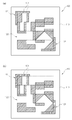
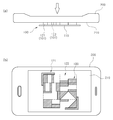
도 1은 본 발명의 일 실시예에 따른 접촉식 전자 인식 코드의 형상을 개념적으로 도시한 사시도이고, 도 2는 본 발명의 일 실시예에 따른 접촉식 전자 인식 코드의 형상을 개념적으로 도시한 평면도이고, 도 3은 본 발명의 일 실시예에 따른 접촉식 전자 인식 코드를 인식하는 방식을 설명하기 위한 도면이다.FIG. 1 is a perspective view conceptually showing a shape of a contact type electronic recognition code according to an embodiment of the present invention, and FIG. 2 is a plan view schematically showing a shape of a contact type electronic recognition code according to an embodiment of the present invention. FIG. 3 is a diagram for explaining a method of recognizing a contact type electronic recognition code according to an embodiment of the present invention.
본 발명의 일 실시예에 따른 접촉식 전자 인식 코드(100)는 바코드 또는 큐알 코드와 마찬가지로 특정 패턴 형상을 통해 정보를 저장하는 것으로, 평면적인 구성이 아니라 입체적인 구성으로 단말기에 접촉하는 형태로 인식 가능하게 형성되는데, 베이스부(110) 및 코드 패턴부(120)를 포함하여 구성된다.The contact type
베이스부(110)는 단순한 평판 형태로 형성될 수 있으며, 코드 패턴부(120)는 이러한 베이스부(110)의 일측면에 양각 형태로 볼록 돌출된 형태의 코드 패턴(101)을 갖도록 형성된다.The
베이스부(110)와 코드 패턴부(120)는 일체형으로 형성될 수 있다. 즉, 평판형의 베이스부(110)를 코드 패턴(101) 형상에 따라 식각 등의 방식으로 패턴 이외의 영역을 제거하는 형태로 일체형으로 형성될 수 있다. 물론, 코드 패턴(101)의 종류에 따라서는 베이스부(110)에 별도의 코드 패턴(101)를 부착시키는 방식으로도 제작 가능할 것이다.The
이러한 코드 패턴부(120)는 베이스부(110)에 양각 형태로 형성되어 별도의 단말기(200)에 접촉하는 방식으로 코드 패턴(101)이 인식되도록 형성되는데, 이때, 단말기(200)에는 코드 패턴(101)의 접촉을 인식할 수 있는 구성이 필요하다. 예를 들면, 스마트 폰의 경우, 전면에 터치 스크린 패널(210)이 장착되는데, 이러한 터치 스크린 패널(210)에 코드 패턴(101)이 접촉함으로써, 코드 패턴(101)이 단말기(200)에 인식되도록 할 수 있다.The code pattern unit 120 is formed in a raised shape on the
좀더 자세히 살펴보면, 일반적으로 최근 널리 사용되는 스마트 폰은 전면에 화면이 출력됨과 동시에 사용자의 조작을 위한 접촉을 인식할 수 있도록 터치 스크린 패널(210)이 장착되는데, 이러한 터치 스크린 패널(210)은 정전식, 정압식, 정전기 유도식, 적외선 방식 등 다양한 종류가 있으며, 최근에는 정전식 터치 스크린 패널이 가장 보편적으로 사용되고 있다.In more detail, a smartphone generally used in recent years is equipped with a
본 발명에 따른 코드 패턴부(120)는 이러한 터치 스크린 패널(210)에 접촉하여 인식될 수 있도록 형성되는데, 이를 위해 코드 패턴(101)의 끝단부에는 도 1의 확대도에 도시된 바와 같이 별도의 전도성 물질로 형성되는 접촉 인식부(102)가 형성될 수 있다. 이는, 정전식, 정전기 유도식 터치 스크린 패널의 경우, 전도성 물질이 접촉하는 경우에만 접촉 상태를 인식하기 때문에, 이러한 터치 스크린 패널에 대해 접촉 인식이 가능하기 위해서는 코드 패턴(101)의 끝단부에 전도성 물질로 형성되는 접촉 인식부(102)가 형성되어야 할 것이다. 물론, 정압식 또는 적외선 방식의 터치 스크린 패널에는 이러한 전도성 물질이 반드시 필요하진 않지만, 전도성 물질의 접촉 인식부(102)가 형성되었다고 하더라도 접촉 인식 상태에 문제가 없으므로, 다양한 방식의 터치 스크린 패널에 대해 접촉 인식 가능하기 위해서는 코드 패턴(101)의 끝단부에 전도성 물질의 접촉 인식부(102)가 형성되는 것이 바람직하다.The code pattern part 120 according to the present invention is formed so as to be able to be contacted to the
이때, 코드 패턴부(120)는 이러한 접촉 인식부(102)와 동일한 재질로 일체로 형성될 수도 있고, 이와 달리 별도의 접촉 인식부(102)를 코드 패턴부(120)의 끝단에 부착 또는 도포하는 형태로 형성될 수 있다.At this time, the code pattern unit 120 may be formed integrally with the same material as the
즉, 코드 패턴부(120)는 단말기(200)의 터치 스크린 패널(210)과의 접촉 과정에서 터치 스크린 패널(210)에 대한 손상을 방지하기 위해 고무와 같은 탄성 재질로 형성될 수 있는데, 이 경우, 코드 패턴(101)이 전도성 재질이 아니므로, 코드 패턴(101)의 끝단부에 전도성 물질을 도포하는 형태로 접촉 인식부(102)를 형성할 수 있다. 또는 이와 달리, 코드 패턴(101) 자체를 전도성 재질로 형성함으로써, 즉, 코드 패턴(101)을 접촉 인식부(102)와 동일 재질의 전도성 물질로 형성함으로써, 별도의 전도성 물질을 코드 패턴(101)의 끝단에 도포하지 않아도 터치 스크린 패널(210)에 접촉 인식될 수 있다.That is, the code pattern unit 120 may be formed of an elastic material such as rubber to prevent damage to the
이러한 구성에 따라 본 발명의 일 실시예에 따른 접촉식 전자 인식 코드(100)는 종래 바코드 또는 큐알 코드와는 달리 카메라를 이용하여 촬영할 필요가 없이 단순히 단말기(200)를 접촉하는 방식으로 코드 패턴(101)을 인식할 수 있고, 이에 따라 촬영이 힘든 어두운 곳이나 흔들리는 곳에서도 단말기(200)의 접촉을 통해 용이하게 코드를 인식할 수 있고, 특히, 시각 장애인의 경우에도 단말기(200)를 코드에 접촉시키는 방식으로 편리하게 코드를 인식할 수 있다.According to this configuration, the contact type
즉, 도 3의 (a)에 도시된 바와 같이 단말기(200)의 터치 스크린 패널(210) 부위를 접촉식 전자 인식 코드(100)에 접촉시킴으로써, 터치 스크린 패널(210)에는 도 3의 (b)에 도시된 바와 같이 접촉식 전자 인식 코드(100)의 코드 패턴(101)이 인식되고, 이러한 접촉식 전자 인식 코드(100)의 코드 패턴(101)에 따라 특정 정보가 단말기(200)에 출력되며, 이를 통해 사용자는 다양한 정보를 손쉽게 취득할 수 있다.3 (a), the
한편, 본 발명의 일 실시예에 따른 코드 패턴부(120)는 영역 표시부(121)와, 정보 표시부(122)를 포함할 수 있는데, 영역 표시부(121)는 코드 패턴부(120)의 가장자리 부분에 형성되며 코드 패턴부(120)의 영역을 한정할 수 있도록 코드 패턴(101)이 형성된다. 정보 표시부(122)는 영역 표시부(121)에 의해 한정된 영역 내부에 형성되며 특정 정보를 표현할 수 있도록 코드 패턴(101)이 형성된다.The code pattern unit 120 according to an embodiment of the present invention may include an
즉, 본 발명의 접촉식 전자 인식 코드(100)를 통해 제공하고자 하는 정보는 실질적으로 정보 표시부(122)의 코드 패턴(101)을 통해 제공되며, 영역 표시부(121)는 이러한 정보 표시부(122)의 영역을 한정 제한하는 기능을 수행한다. That is, the information to be provided through the contact type
예를 들면, 도 2에 도시된 바와 같이 영역 표시부(121)는 정보 표시부(122)의 코드 패턴(101)이 4x4 단위 셀 영역이라는 정보를 표현하거나, 이와 달리 8x8 또는 6x6 단위 셀 영역이라는 정보를 표현할 수 있다. For example, as shown in FIG. 2, the
따라서, 이러한 접촉식 전자 인식 코드(100)를 인식하는 과정에서, 영역 표시부(121)에 의해 한정된 영역의 외부 영역에서 특정 문양이 접촉되었다고 하더라도, 이는 해당 정보 표시부(122)의 코드 패턴(101)이 아닌 것으로 판독할 수 있다.Therefore, even if a specific pattern comes into contact with an area outside the area defined by the
이러한 구조에 따라 접촉식 전자 인식 코드(100)가 단말기(200)와 접촉하는 과정에서 사용자의 부주의에 의해 손가락이 터치 스크린 패널(210)에 접촉하거나 또는 다른 이물질이 접촉하더라도 이는 영역 표시부(121)에 의해 한정된 영역 이외의 외부 영역에서 접촉된 것이므로, 정상적인 코드 패턴(101)이 아닌 것으로 판독하여 노이즈를 제거할 수 있으며, 따라서, 접촉 인식에 대한 정확도가 향상되며, 아울러, 한정된 영역에서 인식된 코드 패턴(101)만 판독하면 되므로, 코드 패턴(101)에 대한 판독 작업이 더욱 신속하게 이루어질 수 있다.According to such a structure, even if a finger touches the
한편, 이러한 영역 표시부(121)에 형성된 코드 패턴(101)은 전술한 바와 같이 코드 패턴부(120)의 영역을 한정함과 동시에 정보 표시부(122)에 표현되는 정보의 특성을 표시할 수 있도록 형성될 수 있다. 즉, 정보 표시부(122)에 표현되는 정보가 어느 것에 대한 것인지 여부를 알려주는 표제부 기능을 수행하도록 형성될 수 있다.The
예를 들면, 영역 표시부(121)는 정보 표시부(122)에 의해 표현되는 정보가 예를 들어, 교통 정보에 관한 것인지, 장소에 관한 것인지, 날씨에 관한 것인지 등등 그 정보에 대한 분류 기준을 나누어 이를 표현할 수 있다. 즉, 도 2의 (a) 및 (b)에 도시된 바와 같이 영역 표시부(121)의 코드 패턴(101)이 서로 다르게 형성될 수 있으며, 이 경우, 각각 정보 표시부(122)에 의해 표현되는 정보는 서로 다른 종류의 정보를 표현하게 된다. For example, the
이와 같이 정보 표시부(122)에 의해 표현되는 정보의 특성을 영역 표시부(121)를 통해 나타냄으로써, 코드 판독 과정에서 더욱 신속하고 정확한 판독 작업이 가능하다.By displaying the characteristics of the information represented by the
물론, 전술한 바와 같이 영역 표시부(121)가 코드 패턴부(120)의 영역을 한정하는 경우에도, 예를 들어 코드 패턴부(120)의 영역이 4x4 또는 8x8 인지 여부를 표시하는 경우에도, 도 2의 (a) 및 (b)에 도시된 영역 표시부(121)의 코드 패턴(101)과 같이 서로 다르게 표현될 수 있다.
Of course, even when the
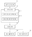
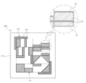
도 4는 본 발명의 일 실시예에 따른 접촉식 전자 인식 코드를 이용한 정보 제공 방법을 동작 흐름에 따라 도시한 도면이고, 도 5는 본 발명의 일 실시예에 따른 접촉식 전자 인식 코드를 이용한 정보 제공 방법의 검증 단계를 설명하기 위한 도면이다.FIG. 4 is a diagram illustrating an information providing method using a contact-type electronic recognition code according to an embodiment of the present invention in an operational flow. FIG. 5 is a flowchart illustrating a method of providing information using a contact-type electronic recognition code according to an embodiment of the present invention. FIG. 7 is a diagram for explaining a verification step of a providing method. FIG.
본 발명은 이상에서 설명한 접촉신 전자 인식 코드(100)를 이용한 정보 제공 방법을 제공하는데, 이는 접촉 인식 단계(S1)와, 판독 단계(S2)와, 정보 출력 단계(S4)를 포함하여 구성되며, 검증 단계(S3)와, 에러 출력 단계(S5)를 더 포함할 수 있다.The present invention provides an information providing method using the contact new
접촉 인식 단계(S1)는 도 1 내지 도 3에서 설명한 바와 같이 접촉식 전자 인식 코드(100)의 코드 패턴(101)이 양각 형태로 돌출 형성되기 때문에, 이를 단말기(200)의 터치 스크린 패널(210)에 접촉시키는 방식으로 진행되고, 이에 따라 터치 스크린 패널(210)에 의해 코드 패턴(101)이 접촉 인식된다.Since the
판독 단계(S2)는 접촉 인식 단계(S1)를 통해 인식된 접촉식 전자 인식 코드(100)를 단말기(200)에 저장된 코드 운영 프로그램을 통해 판독하는 방식으로 진행된다. 코드 운영 프로그램은 스마트폰의 애플리케이션 형태로 프로그램화되어 단말기에 저장될 수도 있고, 스마트폰의 자체 운영 프로그램 형태로 스마트폰에 저장될 수 있다.The reading step S2 proceeds by reading the recognized tactile
이때, 코드 운영 프로그램은 애플리케이션 형태로 접촉식 전자 인식 코드(100)와의 접촉 인식 단계(S1)에서 작동 대기하여 코드 패턴(101)을 인식하고 판독하도록 구성될 수도 있으며, 이와 달리 자체 운영 프로그램 형태로 단순히 터치 스크린 패널(210)에 코드 패턴(101)이 접촉하게 되면, 그 즉시 코드 패턴(101)을 인식하여 판독하도록 구성될 수도 있다.At this time, the code operating program may be configured to recognize and read the
판독 단계(S2)는 코드 패턴부(120)의 영역 표시부(121)의 코드 패턴(101)을 판독하는 영역 표시부 판독 단계(S2-1)와, 영역 표시부(121)에 의해 한정된 영역에서 접촉 인식된 코드 패턴(101)을 판독하는 정보 표시부 판독 단계(S2-2)를 포함하여 구성될 수 있다.The reading step S2 includes an area display reading step S2-1 of reading out the
이때, 영역 표시부(121)는 전술한 바와 같이 정보 표시부(122)와는 다른 특정 코드 패턴을 갖도록 형성되는데, 영역 표시부 판독 단계(S2-1)에서는 접촉 인식 단계(S1)를 통해 인식된 코드 패턴(101) 중 영역 표시부(121)에 해당하는 특정 코드 패턴이 인식되는 경우, 이를 영역 표시부(121)의 코드 패턴(101)으로 인식하여 판독한다.At this time, the
이러한 방식으로 영역 표시부(121)를 판독한 이후, 정보 표시부 판독 단계(S2-2)가 수행되는데, 이는 영역 표시부(121)에 따라 한정된 영역에서 접촉 인식된 코드 패턴(101)을 정보 표시부(122)로서 인식하여 해당 영역의 코드 패턴(101)만 판독하는 방식으로 진행된다.After reading the
정보 출력 단계(S4)는 이상에서 설명한 접촉 인식 단계(S1)와, 판독 단계(S2)를 통해 판독된 접촉식 전자 인식 코드(100)에 대한 정보를 단말기(200)에 출력하는 방식으로 수행된다. 단말기(200)에 출력하는 방식은 단말기(200)의 디스플레이 화면에 코드 패턴(101)에 따른 특정 정보를 시각적으로 출력하거나 또는 단말기(200)의 스피커를 통해 청각적으로 출력하는 등 다양한 방식으로 설정될 수 있다.The information output step S4 is performed in such a manner that information on the contact type
이때, 정보 출력 단계(S4)가 수행되기 전, 즉, 판독 단계(S2) 이후 별도의 검증 단계(S3)를 수행할 수 있는데, 검증 단계(S3)는 판독 단계(S2)를 통해 판독된 접촉식 전자 인식 코드(100)가 정확한지 여부를 검증하는 방식으로 진행되며, 이러한 검증 단계(S3)를 수행한 이후 정보 출력 단계(S4)가 수행되거나 또는 별도의 에러 출력 단계(S5)가 수행될 수 있다.At this time, a separate verification step (S3) can be performed before the information output step (S4) is performed, that is, after the reading step (S2), wherein the verification step (S3) The information output step S4 may be performed after the verification step S3 is performed or a separate error output step S5 may be performed have.
검증 단계(S3)는 다양한 방식으로 수행될 수 있는데, 예를 들면, 접촉 인식된 코드 패턴(101)이 미리 설정된 기준 패턴과 일치하는지 여부를 판단할 수도 있고, 영역 표시부(121)에 의해 한정된 영역 내부에 특정 개수의 단위 셀 영역이 존재하는지 여부를 판단할 수도 있으며, 영역 표시부 판독 단계(S2-1)를 통해 판독된 정보 표시부(122)의 정보 특성과 정보 표시부 판독 단계(S2-2)를 통해 판독된 정보 표시부(122)의 정보 특성이 동일한지 여부를 판단할 수도 있는 등 다양한 방식으로 수행될 수 있다. 물론, 이러한 검증 방식들이 모두 수행될 수도 있다.The verification step S3 may be performed in various ways. For example, it may be determined whether or not the contact-recognized
접촉 인식된 코드 패턴(101)이 미리 설정된 기준 패턴과 일치하는지 여부를 판단하는 과정에서는, 코드 패턴(101)과 기준 패턴과의 차이가 일정한 오차 범위 이내인 경우, 접촉식 전자 인식 코드(100)가 정확한 것으로 판단할 수 있다.When the difference between the
즉, 코드 패턴부(120)는 전술한 바와 같이 고무와 같은 탄성 재질로 형성될 수 있는데, 이 경우, 단말기(200)의 접촉 압력에 따라 코드 패턴(101)과 단말기(200)의 상호 접촉 면적이 미세하게 변화할 수 있다. 예를 들어, 단말기(200)의 접촉 압력이 상대적으로 작으면, 도 5에 도시된 바와 같이 코드 패턴(101)의 접촉 면적(S)은 미리 설정된 기준 패턴의 접촉 면적(S')보다 작게 형성될 수 있으며, 이 경우, 정상적인 코드 패턴(101)으로 인식하지 못할 수 있다. 따라서, 검증 단계(S3)에서는 코드 패턴(101)과 기준 패턴과의 차이가 코드 패턴부(120) 전체 영역에서 오차 범위 이내로 작은 경우, 이를 정상적인 코드 패턴(101)으로 인식하도록 할 수 있다.That is, the cord pattern portion 120 may be formed of an elastic material such as rubber, as described above. In this case, the contact area between the
이와 같은 검증 단계(S3)를 통해 접촉 과정에서 발생할 수 있는 코드 패턴(101)에 대한 미세한 접촉 면적의 변화를 자동 보정하는 방식으로 하여 코드 패턴(101)을 정확하게 판독할 수 있다.Through the verification step S3, the
이상에서 설명한 검증 단계(S3)를 통해 접촉식 전자 인식 코드(100)가 정확한 것으로 검증된 경우 상기 정보 출력 단계(S4)가 수행되고, 접촉식 전자 인식 코드(100)가 정확하지 않은 것으로 검증된 경우에는 별도의 에러 메시지를 단말기(200)에 출력하는 에러 출력 단계(S5)가 수행될 수 있다.
If the contact type
이상의 설명은 본 발명의 기술 사상을 예시적으로 설명한 것에 불과한 것으로서, 본 발명이 속하는 기술 분야에서 통상의 지식을 가진 자라면 본 발명의 본질적인 특성에서 벗어나지 않는 범위에서 다양한 수정 및 변형이 가능할 것이다. 따라서, 본 발명에 개시된 실시예들은 본 발명의 기술 사상을 한정하기 위한 것이 아니라 설명하기 위한 것이고, 이러한 실시예에 의하여 본 발명의 기술 사상의 범위가 한정되는 것은 아니다. 본 발명의 보호 범위는 아래의 청구범위에 의하여 해석되어야 하며, 그와 동등한 범위 내에 있는 모든 기술 사상은 본 발명의 권리범위에 포함되는 것으로 해석되어야 할 것이다.
The foregoing description is merely illustrative of the technical idea of the present invention, and various changes and modifications may be made by those skilled in the art without departing from the essential characteristics of the present invention. Therefore, the embodiments disclosed in the present invention are intended to illustrate rather than limit the scope of the present invention, and the scope of the technical idea of the present invention is not limited by these embodiments. The scope of protection of the present invention should be construed according to the following claims, and all technical ideas within the scope of equivalents thereof should be construed as falling within the scope of the present invention.
100: 접촉식 전자 인식 코드
101: 코드 패턴
102: 접촉 인식부
110: 베이스부
120: 코드 패턴부
121: 영역 표시부
122: 정보 표시부
200: 단말기
210: 터치 스크린 패널100: Contact electronic identification code
101: code pattern 102: contact recognition unit
110: base part 120: code pattern part
121: area display section 122: information display section
200: terminal 210: touch screen panel
Claims (10)
별도 단말기의 터치 스크린 패널에 접촉하는 방식으로 인식되도록 상기 베이스부의 일측면에 양각 형태의 코드 패턴을 갖도록 형성되는 코드 패턴부
를 포함하고, 상기 코드 패턴은 상기 터치 스크린 패널에 접촉 인식됨에 따라 상기 단말기에 특정 정보가 출력될 수 있도록 형성되는 것을 특징으로 하는 접촉식 전자 인식 코드.
A base portion; And
A code pattern portion formed on one side of the base portion so as to have a relief pattern,
Wherein the code pattern is formed so that specific information can be output to the terminal as the contact pattern is recognized by the touch screen panel.
상기 코드 패턴의 끝단부에는 상기 터치 스크린 패널에 접촉 인식될 수 있도록 전도성 물질로 형성되는 접촉 인식부가 형성되고, 상기 코드 패턴부는 상기 접촉 인식부와 동일 재질로 일체로 형성되거나 또는 다른 재질로 형성되는 것을 특징으로 하는 접촉식 전자 인식 코드.
The method according to claim 1,
A contact recognition part formed of a conductive material is formed at an end of the code pattern so that the contact pattern can be recognized by the touch screen panel and the code pattern part is integrally formed with the same material as the contact recognition part, Wherein the electronic identification code is a contact electronic identification code.
상기 코드 패턴부는
상기 코드 패턴부의 가장자리 부분에 형성되며 상기 코드 패턴부의 영역을 한정할 수 있도록 코드 패턴이 형성되는 영역 표시부; 및
상기 영역 표시부에 의해 한정된 영역에 형성되며 특정 정보를 표현할 수 있도록 코드 패턴이 형성되는 정보 표시부
를 포함하고, 상기 정보 표시부에 형성된 코드 패턴의 종류에 따라 상기 단말기에서 서로 다른 정보가 출력될 수 있도록 형성되는 것을 특징으로 하는 접촉식 전자 인식 코드.
3. The method of claim 2,
The code pattern portion
An area display unit formed at an edge portion of the code pattern unit and having a code pattern formed therein so as to define an area of the code pattern unit; And
An information display part formed in an area defined by the area display part and having a code pattern formed therein so as to express specific information;
Wherein the information display unit is configured to output different information from the terminal according to a type of a code pattern formed on the information display unit.
상기 영역 표시부에 형성된 코드 패턴은 상기 코드 패턴부의 영역을 한정함과 동시에 상기 정보 표시부에 의해 표현되는 정보의 특성을 표시할 수 있도록 형성되는 것을 특징으로 하는 접촉식 전자 인식 코드.
The method of claim 3,
Wherein the code pattern formed on the area display unit is formed so as to define an area of the code pattern unit and to display characteristics of information represented by the information display unit.
상기 접촉 인식 단계를 통해 인식된 상기 접촉식 전자 인식 코드를 상기 단말기에 저장된 코드 운영 프로그램을 통해 판독하는 판독 단계; 및
상기 판독 단계를 통해 판독된 상기 접촉식 전자 인식 코드에 대한 정보를 상기 단말기에 출력하는 정보 출력 단계
를 포함하는 것을 특징으로 하는 접촉식 전자 인식 코드를 이용한 정보 제공 방법.
A contact recognition step of recognizing the contact type electronic recognition code according to claim 1 through the touch screen panel;
A reading step of reading the contact type electronic recognition code recognized through the contact recognition step through a code operation program stored in the terminal; And
An information output step of outputting information on the contact type electronic recognition code read out through the reading step to the terminal
Wherein the information providing method comprises the steps of:
상기 코드 패턴부에는, 상기 코드 패턴부의 가장자리 부분에 형성되며 상기 코드 패턴부의 영역을 한정할 수 있도록 코드 패턴이 형성되는 영역 표시부와, 상기 영역 표시부에 의해 한정된 영역에 형성되며 특정 정보를 표현할 수 있도록 코드 패턴이 형성되는 정보 표시부가 형성되고,
상기 판독 단계는
상기 영역 표시부의 코드 패턴을 판독하는 영역 표시부 판독 단계; 및
상기 영역 표시부에 의해 한정된 영역에서 접촉 인식된 코드 패턴을 판독하는 정보 표시부 판독 단계
를 포함하는 것을 특징으로 하는 접촉식 전자 인식 코드를 이용한 정보 제공 방법.
6. The method of claim 5,
The code pattern unit may include a region display unit formed at an edge portion of the code pattern unit and having a code pattern formed therein so as to define an area of the code pattern unit, An information display section in which a code pattern is formed is formed,
The reading step
An area display unit reading step of reading a code pattern of the area display unit; And
An information display unit reading step of reading a contact recognized code pattern in an area defined by the area display unit
Wherein the information providing method comprises the steps of:
상기 영역 표시부는 상기 정보 표시부와는 다른 특정 코드 패턴을 갖도록 형성되고,
상기 영역 표시부 판독 단계에서는
상기 접촉 인식 단계를 통해 인식된 코드 패턴 중 영역 표시부에 해당하는 특정 코드 패턴이 인식되는 경우, 이를 영역 표시부의 코드 패턴으로 인식하여 판독하는 것을 특징으로 하는 접촉식 전자 인식 코드를 이용한 정보 제공 방법.
The method according to claim 6,
Wherein the area display unit is formed to have a specific code pattern different from that of the information display unit,
In the area display section reading step
Wherein when a specific code pattern corresponding to the area display unit is recognized among the recognized code patterns through the contact recognition step, the code pattern is recognized as a code pattern of the area display unit and is read out.
상기 판독 단계를 통해 판독된 상기 접촉식 전자 인식 코드가 정확한지 여부를 검증하는 검증 단계
를 더 포함하고, 상기 정보 출력 단계는 상기 검증 단계 이후 수행되는 것을 특징으로 하는 접촉식 전자 인식 코드를 이용한 정보 제공 방법.
6. The method of claim 5,
A verification step of verifying whether the tactual electronic recognition code read through the reading step is correct
Wherein the information output step is performed after the verification step.
상기 검증 단계를 통해 상기 접촉식 전자 인식 코드가 정확한 것으로 검증된 경우 상기 정보 출력 단계가 수행되고,
상기 검증 단계를 통해 상기 접촉식 전자 인식 코드가 정확하지 않은 것으로 검증된 경우에는 별도의 에러 메시지를 상기 단말기에 출력하는 에러 출력 단계가 수행되는 것을 특징으로 하는 접촉식 전자 인식 코드를 이용한 정보 제공 방법.
9. The method of claim 8,
The information output step is performed when the contact electronic recognition code is verified as correct through the verification step,
And an error outputting step of outputting a separate error message to the terminal when the contact-type electronic recognition code is verified to be inaccurate through the verification step. .
상기 검증 단계는
상기 접촉 인식 단계를 통해 인식된 코드 패턴이 미리 설정된 기준 패턴과 일치하는지 여부를 판단하고,
상기 코드 패턴과 기준 패턴과의 차이가 일정한 오차 범위 이내인 경우, 상기 접촉식 전자 인식 코드가 정확한 것으로 판단하는 것을 특징으로 하는 접촉식 전자 인식 코드를 이용한 정보 제공 방법.
10. The method of claim 9,
The verification step
Determining whether the recognized code pattern matches the predetermined reference pattern through the contact recognition step,
When the difference between the code pattern and the reference pattern is within a predetermined error range, the contact type electronic recognition code is determined to be correct.
Priority Applications (1)
| Application Number | Priority Date | Filing Date | Title |
|---|---|---|---|
| KR1020140179087A KR20160071663A (en) | 2014-12-12 | 2014-12-12 | Touch Type Bar-Code and Information Providing Method Using The Same |
Applications Claiming Priority (1)
| Application Number | Priority Date | Filing Date | Title |
|---|---|---|---|
| KR1020140179087A KR20160071663A (en) | 2014-12-12 | 2014-12-12 | Touch Type Bar-Code and Information Providing Method Using The Same |
Publications (1)
| Publication Number | Publication Date |
|---|---|
| KR20160071663A true KR20160071663A (en) | 2016-06-22 |
Family
ID=56364903
Family Applications (1)
| Application Number | Title | Priority Date | Filing Date |
|---|---|---|---|
| KR1020140179087A Abandoned KR20160071663A (en) | 2014-12-12 | 2014-12-12 | Touch Type Bar-Code and Information Providing Method Using The Same |
Country Status (1)
| Country | Link |
|---|---|
| KR (1) | KR20160071663A (en) |
Cited By (5)
| Publication number | Priority date | Publication date | Assignee | Title |
|---|---|---|---|---|
| CN107608551A (en) * | 2017-09-11 | 2018-01-19 | 广东欧珀移动通信有限公司 | Touch operation response method and device |
| US10698533B2 (en) | 2017-09-11 | 2020-06-30 | Guangdong Oppo Mobile Telecommunications Corp., Ltd. | Method for responding to touch operation and electronic device |
| US11061558B2 (en) | 2017-09-11 | 2021-07-13 | Guangdong Oppo Mobile Telecommunications Corp., Ltd. | Touch operation response method and device |
| US11086442B2 (en) | 2017-09-11 | 2021-08-10 | Guangdong Oppo Mobile Telecommunications Corp., Ltd. | Method for responding to touch operation, mobile terminal, and storage medium |
| US11194425B2 (en) | 2017-09-11 | 2021-12-07 | Shenzhen Heytap Technology Corp., Ltd. | Method for responding to touch operation, mobile terminal, and storage medium |
Citations (1)
| Publication number | Priority date | Publication date | Assignee | Title |
|---|---|---|---|---|
| KR20140095370A (en) | 2013-01-24 | 2014-08-01 | 엘지전자 주식회사 | Generation and recognition method of qr code using plural colors and the terminal therefor |
-
2014
- 2014-12-12 KR KR1020140179087A patent/KR20160071663A/en not_active Abandoned
Patent Citations (1)
| Publication number | Priority date | Publication date | Assignee | Title |
|---|---|---|---|---|
| KR20140095370A (en) | 2013-01-24 | 2014-08-01 | 엘지전자 주식회사 | Generation and recognition method of qr code using plural colors and the terminal therefor |
Cited By (7)
| Publication number | Priority date | Publication date | Assignee | Title |
|---|---|---|---|---|
| CN107608551A (en) * | 2017-09-11 | 2018-01-19 | 广东欧珀移动通信有限公司 | Touch operation response method and device |
| CN107608551B (en) * | 2017-09-11 | 2019-08-06 | Oppo广东移动通信有限公司 | Touch operation response method and device |
| US10698533B2 (en) | 2017-09-11 | 2020-06-30 | Guangdong Oppo Mobile Telecommunications Corp., Ltd. | Method for responding to touch operation and electronic device |
| US10901553B2 (en) | 2017-09-11 | 2021-01-26 | Guangdong Oppo Mobile Telecommunications Corp., Ltd. | Method for responding to touch operation and electronic device |
| US11061558B2 (en) | 2017-09-11 | 2021-07-13 | Guangdong Oppo Mobile Telecommunications Corp., Ltd. | Touch operation response method and device |
| US11086442B2 (en) | 2017-09-11 | 2021-08-10 | Guangdong Oppo Mobile Telecommunications Corp., Ltd. | Method for responding to touch operation, mobile terminal, and storage medium |
| US11194425B2 (en) | 2017-09-11 | 2021-12-07 | Shenzhen Heytap Technology Corp., Ltd. | Method for responding to touch operation, mobile terminal, and storage medium |
Similar Documents
| Publication | Publication Date | Title |
|---|---|---|
| EP2626777B1 (en) | Touch panel, mobile terminal, computer readable storage medium and method for detecting a contact | |
| CN112955896B (en) | Method and electronic device for reading bar codes | |
| KR102126816B1 (en) | Fingerprint recognition apparatus and method | |
| TWI684886B (en) | Method and device for generating security problems and identity verification | |
| KR20160071663A (en) | Touch Type Bar-Code and Information Providing Method Using The Same | |
| US20150332439A1 (en) | Methods and devices for hiding privacy information | |
| CN107977659A (en) | A kind of character recognition method, device and electronic equipment | |
| JP2010140322A (en) | Information processing apparatus, information processing method, program, and information processing system | |
| US9904314B2 (en) | Device and method of controlling a display panel based on cover-related information | |
| EP3188078B1 (en) | Method and device for fingerprint identification | |
| CN106296665B (en) | Card image fuzzy detection method and apparatus | |
| KR102753356B1 (en) | An electronic apparatus comprinsing a fingerprint sensor | |
| KR20120100351A (en) | Method for detecting touch strength using sound, device for the same, and user terminal for the same | |
| US20160132760A1 (en) | Dynamic recognizable two-dimensional code for interaction between electronic devices | |
| TW201502964A (en) | Input device and touch panel display system | |
| CN109902687B (en) | Image identification method and user terminal | |
| CN104238845A (en) | Apparatus and Method for Controlling an Interface Based on Bending | |
| US10452262B2 (en) | Flexible display touch calibration | |
| TWI690825B (en) | Electronic device and method with myopia prevention function | |
| CN104076970B (en) | Messaging device and method | |
| CN114503062A (en) | Construction identified by touch-sensitive sensor matrix | |
| US20180027670A1 (en) | Electronic device with screen-cleaning function | |
| CN105808107A (en) | Picture processing device and method | |
| US20160124624A1 (en) | Electronic device and web page resizing method | |
| KR20170065176A (en) | Method and electronic device being capable of sensing pressure |
Legal Events
| Date | Code | Title | Description |
|---|---|---|---|
| A201 | Request for examination | ||
| PA0109 | Patent application |
Patent event code: PA01091R01D Comment text: Patent Application Patent event date: 20141212 |
|
| PA0201 | Request for examination | ||
| E902 | Notification of reason for refusal | ||
| PE0902 | Notice of grounds for rejection |
Comment text: Notification of reason for refusal Patent event date: 20151127 Patent event code: PE09021S01D |
|
| E902 | Notification of reason for refusal | ||
| PE0902 | Notice of grounds for rejection |
Comment text: Notification of reason for refusal Patent event date: 20160215 Patent event code: PE09021S01D |
|
| E701 | Decision to grant or registration of patent right | ||
| PE0701 | Decision of registration |
Patent event code: PE07011S01D Comment text: Decision to Grant Registration Patent event date: 20160510 |
|
| PG1501 | Laying open of application | ||
| NORF | Unpaid initial registration fee | ||
| PC1904 | Unpaid initial registration fee |