KR20160071350A - Pump and cleaning apparatus - Google Patents
Pump and cleaning apparatus Download PDFInfo
- Publication number
- KR20160071350A KR20160071350A KR1020150176991A KR20150176991A KR20160071350A KR 20160071350 A KR20160071350 A KR 20160071350A KR 1020150176991 A KR1020150176991 A KR 1020150176991A KR 20150176991 A KR20150176991 A KR 20150176991A KR 20160071350 A KR20160071350 A KR 20160071350A
- Authority
- KR
- South Korea
- Prior art keywords
- pump
- cover body
- stator
- rotor
- motor
- Prior art date
Links
Images


Classifications
-
- F—MECHANICAL ENGINEERING; LIGHTING; HEATING; WEAPONS; BLASTING
- F04—POSITIVE - DISPLACEMENT MACHINES FOR LIQUIDS; PUMPS FOR LIQUIDS OR ELASTIC FLUIDS
- F04D—NON-POSITIVE-DISPLACEMENT PUMPS
- F04D13/00—Pumping installations or systems
- F04D13/02—Units comprising pumps and their driving means
- F04D13/06—Units comprising pumps and their driving means the pump being electrically driven
-
- F—MECHANICAL ENGINEERING; LIGHTING; HEATING; WEAPONS; BLASTING
- F04—POSITIVE - DISPLACEMENT MACHINES FOR LIQUIDS; PUMPS FOR LIQUIDS OR ELASTIC FLUIDS
- F04D—NON-POSITIVE-DISPLACEMENT PUMPS
- F04D29/00—Details, component parts, or accessories
- F04D29/60—Mounting; Assembling; Disassembling
- F04D29/62—Mounting; Assembling; Disassembling of radial or helico-centrifugal pumps
- F04D29/628—Mounting; Assembling; Disassembling of radial or helico-centrifugal pumps especially adapted for liquid pumps
-
- A—HUMAN NECESSITIES
- A47—FURNITURE; DOMESTIC ARTICLES OR APPLIANCES; COFFEE MILLS; SPICE MILLS; SUCTION CLEANERS IN GENERAL
- A47L—DOMESTIC WASHING OR CLEANING; SUCTION CLEANERS IN GENERAL
- A47L15/00—Washing or rinsing machines for crockery or tableware
- A47L15/42—Details
- A47L15/4214—Water supply, recirculation or discharge arrangements; Devices therefor
- A47L15/4225—Arrangements or adaption of recirculation or discharge pumps
-
- D—TEXTILES; PAPER
- D06—TREATMENT OF TEXTILES OR THE LIKE; LAUNDERING; FLEXIBLE MATERIALS NOT OTHERWISE PROVIDED FOR
- D06F—LAUNDERING, DRYING, IRONING, PRESSING OR FOLDING TEXTILE ARTICLES
- D06F39/00—Details of washing machines not specific to a single type of machines covered by groups D06F9/00 - D06F27/00
- D06F39/08—Liquid supply or discharge arrangements
- D06F39/083—Liquid discharge or recirculation arrangements
- D06F39/085—Arrangements or adaptations of pumps
-
- F—MECHANICAL ENGINEERING; LIGHTING; HEATING; WEAPONS; BLASTING
- F04—POSITIVE - DISPLACEMENT MACHINES FOR LIQUIDS; PUMPS FOR LIQUIDS OR ELASTIC FLUIDS
- F04D—NON-POSITIVE-DISPLACEMENT PUMPS
- F04D1/00—Radial-flow pumps, e.g. centrifugal pumps; Helico-centrifugal pumps
-
- F—MECHANICAL ENGINEERING; LIGHTING; HEATING; WEAPONS; BLASTING
- F04—POSITIVE - DISPLACEMENT MACHINES FOR LIQUIDS; PUMPS FOR LIQUIDS OR ELASTIC FLUIDS
- F04D—NON-POSITIVE-DISPLACEMENT PUMPS
- F04D13/00—Pumping installations or systems
- F04D13/02—Units comprising pumps and their driving means
- F04D13/06—Units comprising pumps and their driving means the pump being electrically driven
- F04D13/0693—Details or arrangements of the wiring
-
- F—MECHANICAL ENGINEERING; LIGHTING; HEATING; WEAPONS; BLASTING
- F04—POSITIVE - DISPLACEMENT MACHINES FOR LIQUIDS; PUMPS FOR LIQUIDS OR ELASTIC FLUIDS
- F04D—NON-POSITIVE-DISPLACEMENT PUMPS
- F04D29/00—Details, component parts, or accessories
- F04D29/08—Sealings
-
- F—MECHANICAL ENGINEERING; LIGHTING; HEATING; WEAPONS; BLASTING
- F04—POSITIVE - DISPLACEMENT MACHINES FOR LIQUIDS; PUMPS FOR LIQUIDS OR ELASTIC FLUIDS
- F04D—NON-POSITIVE-DISPLACEMENT PUMPS
- F04D29/00—Details, component parts, or accessories
- F04D29/18—Rotors
- F04D29/22—Rotors specially for centrifugal pumps
-
- F—MECHANICAL ENGINEERING; LIGHTING; HEATING; WEAPONS; BLASTING
- F04—POSITIVE - DISPLACEMENT MACHINES FOR LIQUIDS; PUMPS FOR LIQUIDS OR ELASTIC FLUIDS
- F04D—NON-POSITIVE-DISPLACEMENT PUMPS
- F04D29/00—Details, component parts, or accessories
- F04D29/40—Casings; Connections of working fluid
- F04D29/42—Casings; Connections of working fluid for radial or helico-centrifugal pumps
- F04D29/426—Casings; Connections of working fluid for radial or helico-centrifugal pumps especially adapted for liquid pumps
-
- H—ELECTRICITY
- H02—GENERATION; CONVERSION OR DISTRIBUTION OF ELECTRIC POWER
- H02K—DYNAMO-ELECTRIC MACHINES
- H02K1/00—Details of the magnetic circuit
- H02K1/06—Details of the magnetic circuit characterised by the shape, form or construction
- H02K1/12—Stationary parts of the magnetic circuit
- H02K1/14—Stator cores with salient poles
- H02K1/141—Stator cores with salient poles consisting of C-shaped cores
- H02K1/143—Stator cores with salient poles consisting of C-shaped cores of the horse-shoe type
-
- H—ELECTRICITY
- H02—GENERATION; CONVERSION OR DISTRIBUTION OF ELECTRIC POWER
- H02K—DYNAMO-ELECTRIC MACHINES
- H02K5/00—Casings; Enclosures; Supports
- H02K5/04—Casings or enclosures characterised by the shape, form or construction thereof
-
- H—ELECTRICITY
- H02—GENERATION; CONVERSION OR DISTRIBUTION OF ELECTRIC POWER
- H02P—CONTROL OR REGULATION OF ELECTRIC MOTORS, ELECTRIC GENERATORS OR DYNAMO-ELECTRIC CONVERTERS; CONTROLLING TRANSFORMERS, REACTORS OR CHOKE COILS
- H02P27/00—Arrangements or methods for the control of AC motors characterised by the kind of supply voltage
- H02P27/02—Arrangements or methods for the control of AC motors characterised by the kind of supply voltage using supply voltage with constant frequency and variable amplitude
-
- D—TEXTILES; PAPER
- D06—TREATMENT OF TEXTILES OR THE LIKE; LAUNDERING; FLEXIBLE MATERIALS NOT OTHERWISE PROVIDED FOR
- D06F—LAUNDERING, DRYING, IRONING, PRESSING OR FOLDING TEXTILE ARTICLES
- D06F2103/00—Parameters monitored or detected for the control of domestic laundry washing machines, washer-dryers or laundry dryers
- D06F2103/44—Current or voltage
- D06F2103/48—Current or voltage of the motor driving the pump
-
- D—TEXTILES; PAPER
- D06—TREATMENT OF TEXTILES OR THE LIKE; LAUNDERING; FLEXIBLE MATERIALS NOT OTHERWISE PROVIDED FOR
- D06F—LAUNDERING, DRYING, IRONING, PRESSING OR FOLDING TEXTILE ARTICLES
- D06F33/00—Control of operations performed in washing machines or washer-dryers
- D06F33/30—Control of washing machines characterised by the purpose or target of the control
- D06F33/47—Responding to irregular working conditions, e.g. malfunctioning of pumps
Abstract
Description
본 발명은 펌프에 관한 것이며, 상세하게는 펌프 하우징과 모터 커버 본체용 장착 구조에 관한 것이다.The present invention relates to a pump, and more particularly, to a mounting structure for a pump housing and a motor cover main body.
사람들의 생활 수준이 발전함에 따라, 세탁기 또는 식기 세척기와 같은 가정용 세척 장치가 널리 사용되어 오고 있다. 배수 펌프가 세탁기 또는 식기 세척기에서 중요한 부분이다. 배수 펌프의 진동을 감소시키라는 요구가 증가하고 있다.BACKGROUND OF THE INVENTION As people's living standards evolve, household washing devices such as washing machines or dishwashers have been widely used. A drain pump is an important part of a washing machine or dishwasher. There is an increasing demand to reduce the vibration of the drainage pump.
따라서, 진동을 감소시킬 수 있는 펌프에 대한 바램이 있다.Therefore, there is a desire for a pump that can reduce vibration.
일 양상으로서, 펌프가 제공된다. 펌프는, 펌프 챔버를 갖는 펌프 하우징, 펌프 챔버와 연통하는 입구와 출구, 펌프 챔버에 회전 가능하게 배열되는 임펠러, 및 임펠러를 구동하는 모터를 포함한다. 모터는 고정자, 고정자에 대해 회전 가능한 회전자, 및 펌프 하우징에 고정되는 모터 커버 본체를 포함한다. 모터 커버 본체는 펌프 하우징에 연결되는 측벽을 포함하고, 펌프 하우징은 적어도 한 쌍의 위치지정 돌출부를 포함하며, 측벽은 한 쌍의 위치지정 돌출부 사이에 삽입된다.In an aspect, a pump is provided. The pump includes a pump housing having a pump chamber, an inlet and an outlet communicating with the pump chamber, an impeller rotatably arranged in the pump chamber, and a motor for driving the impeller. The motor includes a stator, a rotor rotatable relative to the stator, and a motor cover body fixed to the pump housing. The motor cover body includes a side wall connected to the pump housing, the pump housing including at least a pair of positioning projections, the side walls being inserted between the pair of positioning projections.
바람직하게도, 한 쌍의 위치지정 돌출부 사이의 폭은 위치지정 돌출부의 자유 단부로부터 근원부(root)로 점진적으로 감소하여, 측벽에 가해지는 압력이 점진적으로 증가한다.Preferably, the width between the pair of positioning projections gradually decreases from the free end of the positioning projection to the root, so that the pressure applied to the side wall gradually increases.
바람직하게도, 한 쌍의 위치지정 돌출부의 두 개의 위치지정 면은 서로 오프셋되어 있다.Preferably, the two locating surfaces of the pair of locating projections are offset from one another.
바람직하게도, 스냅 잠금 구조가 측벽과 펌프 하우징 사이에 형성된다.Preferably, a snap lock structure is formed between the side wall and the pump housing.
바람직하게도, 펌프 하우징은 커버 본체와, 커버 본체에 장착되는 바닥 판을 포함하고, 탄성 아암이 바닥 판의 외부 원주 방향 에지에 형성되어 위로 경사지게 연장하고, 탄성 아암은 탄성 아암의 본체에 대해 아래로 오목한 단차가 있는 자유 단부를 가지고, 블록이 커버 본체의 외부 원주면 상에 형성되며 원주 방향으로 단차와 맞물려서 커버 본체와 바닥 판 사이의 상대적인 원주 방향 움직임을 제한한다.Preferably, the pump housing includes a cover body and a bottom plate mounted to the cover body, wherein the resilient arm is formed at the outer circumferential edge of the bottom plate and extends upwardly inclined, The block having a free end with a concave stepped portion, the block being formed on the outer circumferential surface of the cover body and engaging with the step in the circumferential direction to limit relative circumferential movement between the cover body and the bottom plate.
바람직하게도, 스냅 잠금 구조가 커버 본체와 바닥 판 사이에 형성되며, 스냅 잠금 구조는 바닥 판과 커버 본체 사이의 상대적인 원주 방향 회전에 의해 서로와 스냅 방식으로 잠긴다.Preferably, a snap lock structure is formed between the cover body and the bottom plate, and the snap lock structure is snap-locked with respect to each other by a relative circumferential rotation between the bottom plate and the cover body.
바람직하게도, 펌프 하우징은 커버 본체, 커버 본체에 장착되는 바닥 판, 및 커버 본체를 바닥 판에 밀폐하여 연결하는 시일링 링(104)을 포함하며, 시일링 링은 바닥 판의 방사상 홈에 위치한다.Preferably, the pump housing includes a cover body, a bottom plate mounted to the cover body, and a
바람직하게도, 고정자는 고정자 코어와 고정자 코어 주위에 감기는 고정자 권선을 포함하고, 고정자 코어는 한 쌍의 대향 극과 극 사이에 연결되는 요크를 포함하고, 펌프 하우징은 커버 본체와 커버 본체에 장착되는 바닥 판을 포함하고, 바닥 판은 개구로부터 일체형으로 축방향으로 그리고 외부로 연장하는 회전자 하우징을 포함하고, 회전자 하우징은 한 쌍의 극 사이에 고정되며, 회전자는 회전자 하우징 내에서 회전 가능하게 지지된다.Preferably, the stator includes a stator core and a stator winding wound around the stator core, wherein the stator core includes a yoke connected between the pair of opposite poles and the pole, and the pump housing is mounted to the cover body and the cover body The bottom plate includes a rotor housing extending axially and outwardly integrally from the opening, the rotor housing being fixed between a pair of poles, the rotor being rotatable within the rotor housing .
바람직하게도, 모터는 고정자에 고정되는 회로 기판을 더 포함하며, 회로 기판은 회전자의 자극의 위치를 검출하기 위해 기판 상에 설치되는 위치 센서를 포함하며, 위치 센서는 회전자 하우징 외부에 배열된다.Preferably, the motor further comprises a circuit board fixed to the stator, the circuit board comprising a position sensor mounted on the substrate for detecting the position of the magnetic pole of the rotor, the position sensor being arranged outside the rotor housing .
바람직하게도, 회로 기판은 구동 회로를 더 포함하며, 구동 회로는, 위치 센서에 의해 검출되는 자극 위치를 기초로 하여, 고정자 권선에 미리 결정된 방식으로 에너지가 공급되어, 모터에 전원이 공급될 때마다 회전자가 고정된 시동 방향을 가짐을 보장하도록 구성된다.Preferably, the circuit board further comprises a drive circuit, wherein the drive circuit supplies energy to the stator windings in a predetermined manner, based on the magnetic pole position detected by the position sensor, So as to ensure that the rotor has a fixed starting direction.
다른 양상에서, 세척 챔버가 제공된다. 세척 장치는, 세척 챔버, 세척수를 세척 챔버에 공급하는 급수 통로, 배수를 위한 배수 통로, 및 세척 챔버의 세척수를 배수 통로에 펌핑하는 배수 펌프를 포함한다. 배수 펌프는 앞서 기재한 바와 같은 펌프의 특성을 포함한다.In another aspect, a cleaning chamber is provided. The cleaning apparatus includes a cleaning chamber, a water passage for supplying the cleaning water to the cleaning chamber, a drainage passage for drainage, and a drain pump for pumping the wash water of the cleaning chamber into the drainage passage. The drainage pump includes the characteristics of a pump as described above.
본 발명의 바람직한 실시예는 이제, 수반하는 도면의 도면들을 참조하여 오직 예를 들어서 기재될 것이다. 도면들에서, 하나보다 많은 도면에서 나타나는 동일한 구조, 요소 또는 부분은 일반적으로 이들이 나타나는 모든 도면에서 동일한 참조 번호로 표시한다. 도면들에 도시한 구성요소와 특성의 치수는 일반적으로 표시의 편의성 및 명료성을 위해서 선택하였으며 반드시 실제 축적대로 도시되어 있지는 않다. 도면 목록은 아래와 같다.Preferred embodiments of the present invention will now be described, by way of example only, with reference to the drawings in the accompanying drawings. In the drawings, identical structures, elements or parts appearing in more than one drawing are generally designated by the same reference numerals throughout all the drawings in which they appear. The dimensions of the components and features shown in the drawings are generally selected for convenience and clarity of presentation and are not necessarily drawn to scale. The list of drawings is as follows.
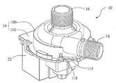
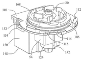
도 1은 본 발명의 일실시예에 따른 펌프를 예시한다.
도 2는 도 1의 펌프의 축방향 횡단면도이다.
도 3은 도 1의 펌프의 모터 회전자의 축방향 횡단면도이다.
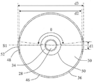
도 4는 도 3의 회전자의 자석을 예시한다.
도 5는 도 3의 모터 회전자의 방사상 횡단면도이다.
도 6은 도 1의 펌프의 모터의 부분 평면도이다.
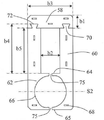
도 7은 도 6의 모터의 고정자 코어의 평면도이다.
도 8은, 도 6의 모터의 고정자의 절연 권선 브래킷의 다른 실시예를 예시한다.
도 9는, 도 6의 모터의 고정자의 절연 권선 브래킷이 수평 방향으로 단부 간에 배치됨을 도시하는 도면이다.
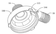
도 10은 도 1의 펌프의 펌프 하우징 커버 본체를 예시한다.
도 11은, 펌프 하우징 커버 본체를 제거한 도 1의 펌프의 도면이다.
도 12는 도 1의 펌프의 모터 회전자의 장착 구조를 예시한다.
도 13은 도 1의 펌프의 바닥 판의 저면도이다.
도 14는 도 1의 펌프의 임펠러를 예시한다.
도 15는 본 발명의 일 실시예에 따른 펌프를 사용하는 식기 세척기를 예시한다.1 illustrates a pump according to an embodiment of the present invention.
Figure 2 is an axial cross-sectional view of the pump of Figure 1;
Figure 3 is an axial cross-sectional view of the motor rotor of the pump of Figure 1;
Figure 4 illustrates a magnet of the rotor of Figure 3;
Figure 5 is a radial, cross-sectional view of the motor rotor of Figure 3;
Figure 6 is a partial top view of the motor of the pump of Figure 1;
7 is a plan view of the stator core of the motor of Fig.
Fig. 8 illustrates another embodiment of the insulated winding bracket of the stator of the motor of Fig.
Fig. 9 is a view showing that the insulated winding brackets of the stator of the motor of Fig. 6 are disposed between the ends in the horizontal direction. Fig.
Figure 10 illustrates a pump housing cover body of the pump of Figure 1;
Figure 11 is a view of the pump of Figure 1 with the pump housing cover body removed.
Figure 12 illustrates the mounting structure of the motor rotor of the pump of Figure 1;
Fig. 13 is a bottom view of the bottom plate of the pump of Fig. 1; Fig.
Figure 14 illustrates an impeller of the pump of Figure 1;
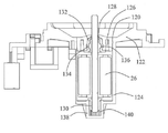
15 illustrates a dishwasher using a pump according to an embodiment of the present invention.
도 1과 도 2를 참조하면, 본 발명의 일 실시예에 따른 펌프(10)는 펌프 챔버(12)를 갖는 펌프 하우징(14), 펌프 챔버(12)와 유체 연통하는 입구(16)와 출구(18), 펌프 챔버(12)에 회전 가능하게 배열되는 임펠러(20), 및 임펠러(20)를 구동하는 모터(22)를 포함한다. 바람직하게도, 모터(22)는 고정자와 고정자에 대해 회전 가능한 회전자(26)를 포함하는 동기 모터이다.1 and 2, a
도 3 내지 도 5를 참조하면, 회전자(26)는 회전 축(28)과, 회전 축(28)에 고정되는 자석(30)을 포함한다. 예시한 실시예에서, 회전자(26)는 대향 극성의 두 개의 극을 형성하는 두 개의 영구 자석(30)을 포함한다. 영구 자석(30)은 오버-몰딩(over-molding) 피스(32)에 의해 회전 축(28)에 고정된다. 오버-몰딩 피스(32)는 내부 링(34), 외부 링(36), 및 내부 링(34)과 외부 링(36)의 대향하는 축방향 단부를 상호 연결하도록 배열되는 두 개의 단부 판(38)을 포함한다. 외부 링(36)은 자석(30) 상에서 오버-몰딩되어 회전 축(28)과 동심원에 있는 외면을 갖는다. 내부 링(34)은 회전 축(28) 상에서 오버-몰딩된다. 두 개의 자석(30)은 내부 링(34)과 외부 링(36) 사이에서 방사상으로 고정되며 두 개의 단부 판(38) 사이에서 축방향으로 고정된다. 요철 구조(39)가 회전 축(28)의 외면 상에 형성되어 오버-몰딩 피스(32)와 회전 축(28) 사이의 본딩 력(bonding force)을 강화시킨다. 각각의 자석(30)은 원주 방향을 따라 원주의 절반을 덮으며, 방사상 외면(40), 방사상 내면(42) 및 자석(30)의 대향 단부에서 방사상 외면(40)과 방사상 내면(42)을 연결하는 두 개의 동일 평면의 연결면(44)을 포함한다. 방사상 외면(40)은 호형 섹션(46)과 호형 부분(46)의 대향 원주 방향 단부로부터 연결면(44)까지 연장하는 두 개의 평면 섹션(48)을 포함한다. 자석(30)은 분말 소재로부터 소결할 수 있다. 평면 섹션(48)은, 연마와 같은 후속 처리를 위해 형성된 자석(30)을 위치 지정하는데 사용될 수 있다. 외면(40)의 호형 섹션(46)은 방사상 내면(42)과 동심원에 있을 수 있다. 두 개의 자석(30)의 방사상 내면(42)은, 통과하게 되는 회전 축(28)을 위해 내부 보어(50)를 협력하여 규정한다. 오버-몰딩 피스(32)의 내부 링(34)은 방사상 내면(42)과 회전 축(28) 사이에 형성된다.3 to 5, the
바람직하게도, 180도의 각도에 대한 각 자석(30)의 극 호 각도(pole arc angle)(θ)의 비는 0.75 내지 0.95의 범위에 있으며, 더욱 상세하게는 0.9 내지 0.95의 범위에 있다. 본 명세서에서 사용되는 용어, "극 호 각도"는, 회전 축(28)의 중심 축과 방사상 외면(40)의 호형 면 섹션(46)의 두 개의 원주 방향 단부를 연결하는 가상의 선에 의해 형성되는 각도를 지칭한다. 하나의 동일 측에서 두 개의 자석(30)의 방사상 외면(40)의 두 개의 평면 섹션(48)은 동일 평면이다. 두 개의 동일 평면 섹션(48)의 두 개의 원주 방향 단부 사이의 거리(d1)는 2mm 내지 9.5mm의 범위에 있다. 오버-몰딩 피스(32)의 외면의 직경(d3)에 대한 두 개의 동일 평면 연결면(44)의 두 개의 외부 단부 사이의 거리(d2)의 비는 0.82 내지 0.95의 범위에 있다. 일 실시예에서, 자석(30)의 극 호 각도(θ)는 166도보다 크며, 두 개의 동일 평면 섹션(48)의 두 개의 원주 방향 단부 사이의 거리(d1)는 2mm 내지 2.5mm의 범위에 있다. 오버-몰딩 피스(32)의 외부 링(36)의 축방향 단부는, 원주 방향으로 이격되어 배열되는 적어도 두 개의 위치지정 홈(52)을 규정하여, 오버-몰딩 피스(32) 형성 공정 동안 두 개의 자석(30)을 위치지정한다. 각각의 위치지정 홈(52)은 두 개의 자석(30)이 서로 접촉하는 영역에 배열되며, 이때 두 개의 자석(30)의 동일 측에서의 두 개의 평면 섹션(48)은 완전히 노출된다.Preferably, the ratio of the pole arc angle [theta] of each
종래의 호형 자석과 비교하여, 본 실시예의 회전자의 자석의 극 호 각도는 증가하며, 이점은 모터의 코깅 토크(cogging torque)를 감소시켜 회전자의 회전을 더 매끄럽게 한다. 링-형 자석과 비교할 때, 본 실시예의 호형 자석은 비용을 감소시킨다.Compared with conventional arc-shaped magnets, the pole angle of the magnets of the rotor of the present embodiment increases, which reduces the cogging torque of the motor and makes the rotation of the rotor smoother. In comparison with the ring-shaped magnet, the arc-shaped magnet of this embodiment reduces the cost.
도 6과 도 7을 참조하면, 고정자는 고정자 코어(54)와 고정자 코어(54) 주위에 감기는 고정자 권선(56)을 포함한다. 본 실시예에서, 고정자 코어(54)는 바닥(58), 바닥(58)의 대향 단부로부터 연장하는 두 개의 브랜치(60), 및 두 개의 브랜치(60) 상에 형성되는 한 쌍의 대향 극(62)을 포함한다. 바람직하게도, 바닥(58)은 바-형상이며, 두 개의 브랜치(60)는 바닥(58)의 대향 단부로부터 평행하게 연장하며, 두 개의 극(62)은 바닥(58)으로부터 먼 단부에서 두 개의 브랜치(60) 상에 형성된다. 각각의 극(62)은, 대응하는 브랜치(60)로부터 연장하며 바닥(58)에 실질적으로 평행한 두 개의 측면(64 및 65)과, 두 개의 측면(64 및 65) 사이의 오목한 극 호형 면(66)을 포함한다. 회전자의 외면은 극 호형 면(66)에 면하며, 이때 그 사이에는 공극이 형성된다.6 and 7, the stator includes a
바람직하게도, 바닥(58)과 두 개의 브랜치(60)는 별도로 형성할 수 있다. 바닥(58)은 다수의 판-형상 바닥 부재의 스택에 의해 형성할 수 있으며, 브랜치(60)는 다수의 판-형상 브랜치 부재의 스택에 의해 형성할 수 있다. 바닥 부재와 브랜치 부재 각각은 조립 구멍(68)을 규정하여 스택된 판-형상 부재를 함께 장착한다. 돌출부(70)가 바닥(58)에 인접한 각 브랜치(60)의 단부의 단면으로부터 돌출하며, 바닥(58)의 대향 단부가 대응하여 두 개의 오목한 부분(72)을 형성한다. 바닥 부재와 브랜치 부재가 조립되어 그 각각의 라미네이션 구조를 형성한 후, 두 개의 브랜치(60)의 돌출부(70)가 바닥(58)의 두 개의 오목한 부분(72)과 스냅 방식으로(snappingly) 연결되어 고정자 코어를 형성한다. 대안적으로, 돌출부(70)는 바닥(58) 상에 형성할 수 있으며, 오목한 부분(72)은 브랜치(60)에 형성할 수 있다. 본 실시예에서, 바닥(58)의 최대 폭(b1)은, 두 개의 브랜치(60)를 함께 붙인 후 이들 사이의 최소 거리(b2)보다 크지 않다. 바닥(58)의 최대 길이(b3)는 바닥에 면하는 브랜치(60)의 측면(64)과 바닥에 인접한 브랜치(60)의 단부의 가장 먼 지점(본 실시예에서는 돌출부(70)의 원단부) 사이의 최대 거리(b4)보다 크지 않다. 앞서 구성한 고정자 코어에서, 바닥(58)은, 브랜치(60)를 형성하는 공정 동안 제거된 두 개의 브랜치(60) 사이의 소재에 의해 형성될 수 있어서, 소재를 절약하며, 그에 따라 비용을 감소시킬 수 있다. 게다가, 바닥(58)의 최대 길이(b3)는 바닥(58)에 면하는 브랜치(60)의 측면(64)과 바닥(58)에 인접한 브랜치(60)의 단부의 단면 사이의 거리(b5)보다 클 수 있다.Preferably, the bottom 58 and the two
두 개의 고정자 극(62)은 고정자 극의 두 개의 원주 방향 단부 각각에서 대향하는 원주 방향 단부 부분(74)을 형성한다. 개방 슬롯(75)이 대향하는 원주 방향 단부 부분 사이에 규정되어, 큰 자기 저항을 형성하며 자기 누설을 감소시킨다. 고정자 극(62)의 극 호형 면(66)과 회전자(26)의 외면은 그 사이에 실질적으로 균일한 공극을 형성한다. 문구, "실질적으로 균일한 공극"은 균일한 공극이 고정자의 대부분과 회전자의 대부분 사이에 형성되며 공극 중 오직 적은 부분만이 균일하지 않은 상황을 지칭한다. 바람직하게도, 고정자 극의 극 호형 면(66)은 회전자와 동심원에 있어서, 균일한 주요 공극(76)을 형성한다. 각각의 극 호형 면(66)은 내부로 오목한 시동(startup) 홈(78)을 형성하여, 불균일 공극이 시동 홈(78)과 회전자(26)의 외면 사이에 형성된다. 바람직하게도, 두 개의 극(62)의 극 호형 면의 두 개의 시동 홈(78)은 회전자의 직경에 대해 대칭이며, 각각 원주 방향 단부 부분(74) 중 대응하는 것으로부터 연장한다. 이 구성은, 회전자(26)가 정지해 있을 때 회전자(26)의 극 축(S1)(도 5)이 고정자 극(62)의 중심 축(S2)으로부터 각도만큼 벗어나 있음을 보장할 수 있어서, 회전자는 모터에 전원이 공급될 때마다 고정된 시작 방향을 갖는다. 극 축은 두 개의 상이한 자극(본 실시예에서는 두 개의 자석) 사이의 경계를 지칭하며, 고정자 극의 중심 축은 두 개의 극(62)의 중심을 통과하는 선을 지칭한다.The two
바람직하게도, 회전자의 극 호형 면과 회전자 사이의 최소 공극(본 실시예에서는 극 호형 면과 회전자 사이의 주요 공극)에 대한 두 개의 고정자 극의 두 개의 대향 원주 방향 단부 부분(74) 사이의 거리(a1)의 비는 2미만이다.Preferably, between two opposite
본 실시예에서, 두 개의 개방 슬롯(75)은 동일하고 균일한 폭을 가지며, 브랜치(60)의 길이 방향에 평행하다. 대안적으로, 각각의 개방 슬롯(75)은 불균일 폭을 가질 수 있다. 이 경우에, 앞서 기재한 바와 같이 두 개의 대향 원주 방향 단부 부분(74) 사이의 거리(a1)는 개방 슬롯(75)의 최소 폭을 지칭한다.In this embodiment, the two
본 실시예의 모터 구성은, 회전자가 고정된 시작 방향을 가지며, 동시에 모터의 코깅 토크를 감소시켜 회전자의 회전을 더 매끄럽게 함을 보장할 수 있다.The motor configuration of this embodiment can ensure that the rotor has a fixed starting direction and at the same time reduces the cogging torque of the motor to make the rotation of the rotor smoother.
도 8 및 도 9를 참조하면, 바람직하게도, 고정자는, 고정자 코어(54)의 두 개의 브랜치(60)의 절연 권선 브래킷(80) 주위에 각각 감기는 한 쌍의 고정자 권선(56)을 포함한다. 모터는, 브랜치(60)에 평행한 방향으로 절연 권선 브래킷(80)에 장착되는 회로 기판(82)(도 2)을 더 포함한다. 과열 보호기(84)가 회로 기판(82)에 장착된다. 과열 보호기(84)는 회로 기판(82)과 두 개의 고정자 권선(56) 사이에 배열되어, 권선(56) 중 어느 하나의 온도가 지나치게 높은 경우에 전원 공급을 차단할 수 있다. 두 개의 고정자 권선(56)은 두 개의 별도의 도체 와이어(86)를 감음으로써 형성할 수 있으며, 이들 와이어는 그 후 서로 전기적으로 연결된다. 각 도체 와이어(86)는 입력 단자(88)와 출력 단자(90)를 갖는다. 두 개의 권선은 동시에 두 개의 도체 와이어(86)를 감음으로써 형성할 수 있으며, 이것은 시간을 절약한다. 두 개의 고정자 권선(56)의 두 개의 입력 단자(88)는 평행한 브랜치(60)의 하나의 길이 방향 단부에 위치하며, 권선의 내부 층에 배열된다. 두 개의 출력 단자(90)는 평행한 브랜치(60)의 다른 하나의 길이 방향 단부에 위치하여 권선의 외부 층에 배열된다. 절연 권선 브래킷(88)은 관상 부분(92)과, 이 관상 부분(92)의 대향 단부로부터 외부로 연장하는 단벽(94)을 포함한다. 권선 공간(95)이 관상 부분(92)의 방사상 외면과 두 개의 단벽(94)의 축방향 대향 면 사이에 형성되어 권선(56)을 수용한다.8 and 9, the stator preferably includes a pair of
입력 단자(88)가 배열되는 측에서 두 개의 절연 브래킷(80)의 단벽(94)은 각각 와이어 안내 슬롯(96)을 형성한다. 두 개의 고정자 권선(56)의 두 개의 입력 단자(88)는 권선 브래킷(80)의 외부로부터 와이어 안내 슬롯(96)을 거쳐 권선 브래킷(80) 내부의 권선 공간(95)으로 라우팅된다. 격벽(98)이 권선 브래킷 내부의 권선 공간(95)과 와이어 안내 슬롯(96) 사이에 형성된다. 격벽(98)은 관상 부분(92)의 외면으로 연장한다. 입력 단자(88)는 격벽(98)에 의해 차단되어, 관상 부분(92)의 외면에 도달할 때까지 권선 공간에 들어가지 않는다. 그러므로 입력 단자(88)는 권선 공간(95)에서 코일의 각 층으로부터 격리되어, 권선 공간에서 코일과 입력 단자 사이의 마찰 접촉으로 인한 코일의 단락 회로를 회피하며, 이러한 마찰 접촉은 도체 와이어의 절연 층을 벗겨 낸다. 바람직하게도, 두 개의 출력 단자(90)는 회로 기판(82)에 납땜되어 전기적으로 연결될 수 있어서, 두 개의 권선(56)은 직렬 연결된다. 두 개의 권선(56)의 두 개의 입력 단자(88)는 외부의 단상 교류 전원에 의해 전원이 공급될 수 있다. 바람직하게도, 도 9에 도시한 바와 같이, 두 개의 절연 권선 브래킷(80)은 일체형으로 형성되고 길이 방향으로 배치되어 바 형상을 갖는다. 두 개의 권선(56)이 권선 브래킷(80) 주위에 감긴 후, 바-형상의 두 개의 권선 브래킷(80)이 서로 평행하게 되도록 구부려진다. 두 개의 평행한 권선 브래킷(80)은 그 후 고정자 코어(54)의 두 개의 평행한 브랜치(60) 주위에 부착된다. 바람직하게도, 두 개의 권선(56)의 두 개의 입력 단자는, 서로로부터 멀리 있는, 바-형상의 두 개의 권선 브래킷(80)의 두 개의 원단부에 배열되거나 바-형상의 두 개의 권선 브래킷(80)의 두 인접한 단부에서 그 중심 부분에 배열되며, 두 개의 권선의 권선 방향은 서로 대향한다. 이처럼, 두 개의 권선 브래킷이 서로 평행하게 되도록 구부려지면, 두 개의 권선의 두 개의 입력 단자는 동일 단부에 배열되며, 직렬로 연결되는 두 개의 권선에 의해 생성되는 자계는 서로 상쇄하지 않는다.On the side where the
도 10 내지 도 12를 참조하면, 펌프 하우징(14)은 커버 본체(100), 커버 본체(100)에 장착되는 바닥 판(102)을 포함한다. 커버 본체(100)는 시일링 링(104)에 의해 바닥 판(102)에 밀폐하여 연결된다. 바람직하게도, 시일링 링(104)은 바닥 판(102)의 방사상 홈(106)에 위치하여, 커버 본체(100)가 바닥 판(102)에 장착되기 전에 시일링 링(104)이 바닥 판(102)으로부터 분리되는 것을 방지한다. 커버 본체(100)는 상부 판(108)과, 상부 판(108)과 바닥 판(102)을 상호 연결하는 측면 인클로징(side enclosing) 판(110)을 포함한다. 입구(16)는 상부 판(108)으로부터 일반적으로 축방향으로 외부로 연장하며, 출구(18)는 축방향에 일반적으로 수직인 방향으로 측면 인클로징 판(110)으로부터 연장한다. 커버 본체(100)와 바닥 판(102)은 그 사이에 펌프 챔버(12)를 형성하며, 임펠러(20)가 펌프 챔버(12)에 회전 가능하게 배열된다.Referring to Figs. 10 to 12, the
스냅 잠금 구조가 커버 본체(100)와 바닥 판(102) 사이에 형성된다. 스냅 잠금 구조는, 바닥 판(102)과 커버 본체(100) 사이의 상대적인 원주 방향 회전에 의해 서로와 스냅 방식으로 잠길 수 있다. 바람직하게도, 복수의 원주 방향으로 연장하는 잠금 슬롯(112)이 바닥 판(102)의 외부 원주 방향 에지에서 형성되며, 복수의 원주 방향으로 연장하는 돌출부(113)가 커버 본체(100)의 외면 상에서 대응하여 형성된다. 원주 방향으로 연장하는 돌출부(113)의 축방향 폭은 원주 방향으로 연장하는 잠금 슬롯(112) 내로 삽입하는 방향으로 점진적으로 감소한다. 탄성 아암(114)이 바닥 판(102)의 외부 원주 방향 에지에 형성되며, 위로 경사지게 연장한다. 탄성 아암은, 아암의 본체에 대해 아래로 오목한 단차(116)를 가진 자유 단을 갖는다. 블록(118)이 커버 본체(100)의 외면 상에 형성된다. 커버 본체(100)가 시계 방향으로 회전할 때, 커버 본체(100)의 원주 방향으로 연장하는 돌출부(113)가 바닥 판(102)의 그 각각의 원주 방향으로 연장하는 잠금 슬롯(112) 내로 삽입되며, 블록(118)이 탄성 아암(114) 위로 슬라이드한다. 원주 방향으로 연장하는 돌출부(113)가 회전하여 그 각각의 잠금 슬롯(112)과 간섭-핏(interference-fit)을 형성하면, 블록(118)은 단차(116)로 단지 슬라이드하여, 커버 본체(100)의 역회전을 방지한다.A snap lock structure is formed between the
바닥 판(102)은, 개구(120)를 갖는 펌프 챔버 바닥 벽(122)과, 개구(120)로부터 일체형으로 축방향으로 그리고 외부로 연장하는 회전자 하우징(124)을 포함한다. 고정된 단부 캡(126)이 개구(120)에 인접한 회전자 하우징(124)의 일 단부에 장착된다. 회전 축(28)의 일 단부가 단부 캡(126)을 통과하여 펌프 챔버(12)에 들어가 임펠러(20)에 연결되어, 임펠러(20)를 회전하도록 구동한다. 회전 축(28)의 대향 단부는 각각 단부 캡(126)에 배열되는 베어링(128)과 개구(120)로부터 먼, 회전자 하우징(124)의 다른 단부에 배열되는 베어링(130)에 의해 지지될 수 있다.The
바람직하게도, 베어링(128)은 충격 흡수재(132)를 통해 단부 캡(126)에 장착할 수 있다. 베어링(128)은 원통 형상이며, 베어링(128)의 외면 상에서 원주 방향으로 연장하는 릿지(134)를 포함한다. 충격 흡수재(132)의 내면은 홈(136)을 형성하여 릿지(134)와 맞물린다. 이러한 구성은 베어링(128)과 회전자 사이가 동심원이 됨을 보장한다. 베어링(130)은 회전자 하우징(124)과 일체형으로 형성되는 베어링 시트(138)에 의해 지지될 수 있다. 복수의 내부 투쓰들(140)이 베어링 시트(138)의 내면 상에 형성되어, 베어링 시트(138)의 내면과 베어링(130)의 외면 사이에 불연속 접촉을 초래한다. 이러한 구성은 동작 동안 모터에 의해 생성되는 진동을 감소시킬 수 있다.Preferably, the
회전자 하우징(124)은 두 개의 고정자 극(62) 사이에 고정한다. 회전자(26)의 외면과 회전자 하우징(124) 사이에는 간극(gap)이 형성되어, 회전자(26)는 회전자 하우징(124)에 대해 회전할 수 있다. (도 11에 도시한) 축방향으로 연장하는 리브(142)가 회전자 하우징(124)의 외면 상에 형성된다. 고정자 극(62)에 인접한 단부에서의 두 개의 절연 권선 브래킷(80)의 두 개의 인접한 측이 협력하여 리브(144)를 형성한다(도 6). 리브(142)와 리브(144)는 두 개의 극(62)의 원주 방향 단부 부분(74) 사이에서 두 개의 개방 슬롯(75) 내에 각각 삽입되어, 고정자 코어(54)의 상대적인 원주 방향 회전을 제한한다. 바람직하게도, 회전자 하우징(124)의 리브(142)의 외면은, 바닥(58)으로부터 먼, 고정자 극(62)의 측면(65)보다 높지 않다.The
도 11 및 도 13을 참조하면, 모터는 회로 기판(82)과 고정자 권선(56)을 덮는 모터 커버 본체(146)를 또한 포함한다. 모터 커버 본체(146)는 바닥 벽(148)과 바닥 벽(148)으로부터 연장하는 두 개의 측벽(150)을 포함한다. 두 개의 측벽(150)은 고정자 코어(54)의 두 개의 측에 배열된다. 회로 기판(82)은 바닥 벽(148)과 고정자 권선(56) 사이에 배열된다.11 and 13, the motor also includes a
본 실시에에서, 모터 커버 본체(146)와 펌프 하우징(14)은, 측벽(150) 상의 돌출 블록(152)과 바닥 판(102)으로부터 아래로 연장하는 후크(154)를 포함하여 후크(154)와 스냅 방식으로 맞물리는 스냅 잠금 구조에 의해 서로 장착된다. 바닥 판(102)은 두 개의 측벽(150)에 대응하는 적어도 한 쌍의 위치지정 돌출부(156)를 포함한다. 측벽(150)은 한 쌍의 위치지정 돌출부(156) 사이에 삽입된다. 바람직하게도, 한 쌍의 위치지정 돌출부(156) 사이의 폭은 돌출부(156)의 자유 단부로부터 근원부(roots)로 점진적으로 감소하여, 측벽(150)과 한 쌍의 위치지정 돌출부(156) 사이의 간섭-피트가 형성될 때까지 측벽(150)에 가해진 압력은 점진적으로 증가한다. 이처럼, 모터 커버 본체(146)와 펌프 하우징(14) 사이의 장착력은 강화되어, 모터의 동작 동안 진동을 감소시킨다.The motor cover
본 실시예에서, 후크(154)는 또한 동시에 위치지정 돌출부(156)로서 기능할 수 있다. 이해할 수 있는 바와 같이, 한 쌍의 위치지정 돌출부(156)는 또한 후크(154)와 독립적으로 별도로 배열될 수 있다. 바람직하게는, 한 쌍의 위치지정 돌출부(156)의 두 개의 위치지정 면은 서로 오프셋되어 있다. 예시한 실시예에서, 한 쌍보다 많은 위치지정 돌출부(156)가 각각의 측에 형성된다. 대안적으로, 단일 쌍의 위치지정 돌출부(156)가 각 측에 형성될 수 있다. 한 쌍보다 많은 위치지정 돌출부(156)인 경우에, 각 쌍의 위치지정 돌출부(156)는 다른 쌍의 위치지정 돌출부(156)와 독립적으로 별도로 배열될 수 있다. 대안적으로, 바-형상의 돌출부(156)가 측벽의 내부 또는 외부에 대응하는 위치에 형성되며, 두 개의 또는 두 쌍보다 많은 위치지정 돌출부(156)가 바-형상의 돌출부(156)를 공유한다.In this embodiment, the
중국 특허출원 번호 제201410404474.2호 및 제201410404755.8호 전체가 본 명세서에서 인용되고 있다. 본 실시예의 모터는, 중국 특허출원 중 어느 하나에서 개시한 구동 회로 또는 다른 적절한 구동 회로와 연계하여 사용될 때, 회전자가 각각의 시동 동안 동일한 방향으로 회전할 수 있음을 보장할 수 있다. 이처럼, 팬 또는 물 펌프와 같은 응용에서, 회전자에 의해 구동되는 임펠러는 만곡된 날개를 활용하여, 팬 또는 물 펌프의 수력 효율(hydraulic efficiency)을 향상시킬 수 있다. 따라서, 더 소형의 모터가 동일한 레벨의 출력을 달성하는데 사용될 수 있어서, 에너지 소비를 감소시킬 수 있다. 구동 회로가 회로 기판(82) 상에 배열될 수 있다. 위치 센서(158)(도 2)에 의해 검출되는 자극 위치 정보를 기반으로 하여, 고정자 권선(56)에는 미리 결정된 방식으로 에너지가 공급되어, 모터에 전원이 공급될 때마다 회전자가 고정된 시동 방향을 가짐을 보장한다. 본 실시예에서, 위치 센서(158)는, 회전자가 정지해 있을 때 회전자의 극 축(S1)의 수직선과 고정자의 중심 축(S2)의 수직선 사이에 형성된 예각의 범위에 배열된다. 위치 센서(158)가 회전자 하우징(124) 외부에 배열되며 모터 커버 본체(146)에 의해 덮인다.The entirety of Chinese Patent Application Nos. 201410404474.2 and 201410404755.8 are hereby incorporated by reference. The motor of this embodiment can ensure that the rotor can rotate in the same direction during each start when used in conjunction with a drive circuit or any other suitable drive circuit as disclosed in any of the Chinese patent applications. Thus, in applications such as a fan or water pump, the impeller driven by the rotor can utilize curved blades to improve the hydraulic efficiency of the fan or water pump. Thus, a smaller motor can be used to achieve the same level of output, thus reducing energy consumption. The driving circuit can be arranged on the
도 14를 참조하면, 임펠러(20)는 회전 축(28)에 고정되게 장착되어 회전 축(28)과 동시에 회전한다. 임펠러(20)는 플라스틱 재료로 만들 수 있으며, 기판(160)과 원주 방향으로 기판(160)에 이격되게 장착되는 복수의 날개(162)를 포함한다. 바람직하게도, 임펠러(20)의 날개(162)는 호 형상이며, 긴 날개(164) 그룹과 짧은 날개(166) 그룹을 포함한다. 두 날개 그룹은 원주 방향으로 기판(160)의 외부 원주 방향 에지에 대안적으로 배열된다. 나선형 흐름 통로(168)(도 11)가 펌프 챔버(12)의 내면과 임펠러(20) 사이에 형성된다. 흐름 통로(168)의 방사상 횡단면적은 출구(18)를 향해 원주 방향으로 점진적으로 증가한다. 회전자가 고정된 시동 회전 방향을 갖는 조건 하에서, 호 형상의 날개와 나선형 흐름 통로는 수력 효율을 향상시킬 수 있다. 장착 포스트(170)가 기판(160)의 중심 영역에 배열된다. 회전 축(28)의 일 단부가 축 슬리브(172)를 통해 장착 포스트(170)에 고정된다. 축 슬리브(172)는 금속 재료로 형성할 수 있다. 바람직하게도, 모터로부터 먼, 장착 포스트(170)의 축 방향 단부에서, 장착 포스트(170), 축 슬리브(172) 및 사출 성형부(174)가 방사상 안쪽에 배치되어 연속해서 폐쇄되는 단면을 협력하여 형성한다. 사출 성형부(174)와 장착 포스트(170)는 브릿지 부(176)를 통해 연결된다. 대안적인 실시예에서, 임펠러(20)는 직선 타입 날개를 활용할 수 있다.Referring to FIG. 14, the
본 명세서에서 기재한 펌프(10)는 상세하게는, 식기 세척기나 세탁기와 같은 세척 장치용 - 하지만 이것으로 제한되지는 않음 - 배수 펌프로서 사용하기에 적절하다. 도 15는 본 발명의 일 실시예에 따른 배수 펌프를 포함하는 식기 세척기(176)를 예시한다. 식기 세척기는 세척 챔버(178), 세척수를 세척 챔버(178)에 공급하는 급수 통로(180), 배수를 위한 배수 통로(182), 세척 챔버(178)에서 세척수를 순환하는 순환 통로(184), 및 배수 펌프(10)와 순환 펌프(186)를 갖는 제어 시스템(188)을 포함한다. 배수 펌프(10)는 세척 챔버(178)의 세척수를 배수 통로(182)에 펌핑하고, 순환 펌프(186)는 세척 챔버(178)의 세척수를 순환 통로(184)에 펌핑한다. 본 발명의 실시예에서 기재한 모터가 또한 다른 응용에서 사용할 수 있음을 이해할 수 있어야 한다.The
본 출원의 상세한 설명 및 청구범위에서, 용어, "포함하다", "갖는다" 및 그 파생어 각각은 포괄적인 의미로 사용되고 있어서, 언급한 항목의 존재를 명시하지만, 추가 항목의 존재를 배제하지는 않는다.In the detailed description and the claims of this application, the terms "comprise," " comprise ", and derivatives thereof, are used in a generic sense to denote the presence of the stated items, but do not preclude the presence of additional items.
본 발명을 하나 이상의 바람직한 실시예를 참조하여 기재하였지만, 여러 변형이 가능함을 당업자는 인식해야 한다. 그러므로 본 발명의 적용범위는 다음의 청구범위를 참조하여 결정될 것이다.While the present invention has been described with reference to one or more preferred embodiments, those skilled in the art should recognize that various modifications are possible. The scope of the invention will, therefore, be determined with reference to the following claims.
Claims (10)
펌프 챔버(12)를 갖는 펌프 하우징(14), 상기 펌프 챔버(12)와 연통하는 입구(16)와 출구(18), 상기 펌프 챔버(12)에 회전 가능하게 배열되는 임펠러(20), 및 상기 임펠러(20)를 구동하는 모터(22)를 포함하며, 상기 모터(22)는 고정자, 상기 고정자에 대해 회전 가능한 회전자(26), 및 상기 펌프 하우징(14)에 고정되는 모터 커버 본체(146)를 포함하고, 상기 모터 커버 본체(146)는 상기 펌프 하우징(14)에 연결되는 측벽(150)을 포함하고, 상기 펌프 하우징(14)은 적어도 한 쌍의 위치지정 돌출부(156)를 포함하며, 상기 측벽(150)은 상기 한 쌍의 위치지정 돌출부(156) 사이에 삽입되는, 펌프.As the pump 10,
A pump housing 14 having a pump chamber 12, an inlet 16 and an outlet 18 in communication with the pump chamber 12, an impeller 20 rotatably arranged in the pump chamber 12, And a motor 22 for driving the impeller 20. The motor 22 includes a stator, a rotator 26 rotatable with respect to the stator, and a motor cover body (not shown) fixed to the pump housing 14. [ Wherein the motor cover body includes a side wall connected to the pump housing and the pump housing includes at least a pair of locating projections And the side wall (150) is inserted between the pair of positioning projections (156).
Applications Claiming Priority (4)
| Application Number | Priority Date | Filing Date | Title |
|---|---|---|---|
| CN201410765091 | 2014-12-11 | ||
| CN201410765091.8 | 2014-12-11 | ||
| CN201510323868.X | 2015-06-12 | ||
| CN201510323868.XA CN106194764A (en) | 2014-12-11 | 2015-06-12 | Pump and cleaning device |
Publications (1)
| Publication Number | Publication Date |
|---|---|
| KR20160071350A true KR20160071350A (en) | 2016-06-21 |
Family
ID=54838236
Family Applications (1)
| Application Number | Title | Priority Date | Filing Date |
|---|---|---|---|
| KR1020150176991A KR20160071350A (en) | 2014-12-11 | 2015-12-11 | Pump and cleaning apparatus |
Country Status (6)
| Country | Link |
|---|---|
| US (1) | US20160169248A1 (en) |
| EP (1) | EP3032706B1 (en) |
| JP (1) | JP6688061B2 (en) |
| KR (1) | KR20160071350A (en) |
| BR (1) | BR102015030908A2 (en) |
| MX (1) | MX2015017013A (en) |
Cited By (1)
| Publication number | Priority date | Publication date | Assignee | Title |
|---|---|---|---|---|
| KR20210059813A (en) * | 2019-11-15 | 2021-05-26 | 주식회사 유니크 | Electronic water pump |
Families Citing this family (4)
| Publication number | Priority date | Publication date | Assignee | Title |
|---|---|---|---|---|
| CN109906543B (en) | 2016-10-26 | 2021-12-10 | 日本电产三协株式会社 | Motor |
| CN109779977B (en) * | 2017-11-14 | 2022-07-12 | 青岛海尔洗涤电器有限公司 | Double-end pump shell structure and washing machine |
| CN108678968B (en) * | 2018-07-17 | 2023-10-13 | 绿美泵业有限公司 | Water pump with automatic exhaust function |
| CN114673659B (en) * | 2022-03-29 | 2023-06-23 | 华能伊敏煤电有限责任公司 | Detachable and replaceable desulfurization circulating water pump |
Family Cites Families (22)
| Publication number | Priority date | Publication date | Assignee | Title |
|---|---|---|---|---|
| GB2177456A (en) * | 1985-07-01 | 1987-01-21 | Easthorpe Investments Ltd | Centrifugal pump |
| US4750872A (en) * | 1985-07-01 | 1988-06-14 | Easthorpe Investments Ltd. | Centrifugal pump with damped motor connection |
| US5833441A (en) * | 1996-06-19 | 1998-11-10 | Itt Automotive Electrical Systems, Inc. | Windshield wiper washer motor for use in a vehicle |
| US5934298A (en) * | 1997-11-14 | 1999-08-10 | Singh; Baljit | Combination sink and dishwasher |
| US6045340A (en) * | 1997-10-10 | 2000-04-04 | Rule Industries, Inc. | Locking mechanism for a removable live well pump |
| DE10204459A1 (en) * | 2002-02-05 | 2003-08-07 | Bosch Gmbh Robert | liquid pump |
| ITPN20030009A1 (en) * | 2003-02-12 | 2004-08-13 | Sole Spa | SINGLE-PHASE ELECTRONICALLY SWITCHED MOTOR. |
| JP2005009461A (en) * | 2003-06-20 | 2005-01-13 | Nidec Shibaura Corp | Assembly structure of casing |
| DE102005039557A1 (en) * | 2005-08-22 | 2007-03-01 | Robert Bosch Gmbh | rotary pump |
| ES2374820T3 (en) * | 2005-08-30 | 2012-02-22 | Askoll Holding S.R.L. | SINGLE-PHASE SYNCHRONOUS ELECTRIC MOTOR OF PERMANENT MAGNETS WITH IMPROVED STATOR STRUCTURE, IN PARTICULAR FOR DISCHARGE PUMPS OF WASHING MACHINES AND SIMILAR APPLIANCES. |
| DE202005014071U1 (en) * | 2005-09-06 | 2007-01-18 | Oase Gmbh | Pump for pond, aquarium or the like. Attachments |
| AU2008202487B2 (en) * | 2007-06-05 | 2013-07-04 | Resmed Motor Technologies Inc. | Blower with Bearing Tube |
| CN100561855C (en) * | 2007-11-13 | 2009-11-18 | 广东博宇水族实业有限公司 | A kind of pumping method and device that adopts alternating current power supply to driving permanent magnet motor submersible pump |
| JP5232548B2 (en) * | 2008-07-02 | 2013-07-10 | 三洋電機株式会社 | Terminal protector for electric compressor |
| JP2010035406A (en) * | 2008-07-04 | 2010-02-12 | Nidec Sankyo Corp | Motor and pump apparatus |
| JP4508286B2 (en) * | 2009-06-08 | 2010-07-21 | パナソニック株式会社 | Dishwasher |
| DE102011005140B4 (en) * | 2011-03-04 | 2013-06-27 | E.G.O. Elektro-Gerätebau GmbH | Locking device for a pump housing and pump |
| JP5953081B2 (en) * | 2012-03-22 | 2016-07-13 | 株式会社不二工機 | Drainage pump |
| WO2013190640A1 (en) * | 2012-06-19 | 2013-12-27 | 三菱電機株式会社 | Pump, method for manufacturing pump, and refrigeration cycle device |
| US9130413B2 (en) * | 2012-07-25 | 2015-09-08 | Nidec Motor Corporation | Electric motor having a partially sealed housing |
| US9263918B2 (en) * | 2012-11-09 | 2016-02-16 | Nidec Motor Corporation | Connection for motor stator segments |
| CN202954989U (en) * | 2012-12-12 | 2013-05-29 | 江门市地尔汉宇电器股份有限公司 | Alternating current permanent magnet drainage pump with improved rotor drum structure |
-
2015
- 2015-12-08 EP EP15198539.7A patent/EP3032706B1/en active Active
- 2015-12-10 BR BR102015030908A patent/BR102015030908A2/en active Search and Examination
- 2015-12-10 US US14/965,405 patent/US20160169248A1/en not_active Abandoned
- 2015-12-10 MX MX2015017013A patent/MX2015017013A/en active IP Right Grant
- 2015-12-11 JP JP2015241971A patent/JP6688061B2/en not_active Expired - Fee Related
- 2015-12-11 KR KR1020150176991A patent/KR20160071350A/en unknown
Cited By (1)
| Publication number | Priority date | Publication date | Assignee | Title |
|---|---|---|---|---|
| KR20210059813A (en) * | 2019-11-15 | 2021-05-26 | 주식회사 유니크 | Electronic water pump |
Also Published As
| Publication number | Publication date |
|---|---|
| JP6688061B2 (en) | 2020-04-28 |
| US20160169248A1 (en) | 2016-06-16 |
| BR102015030908A2 (en) | 2016-08-23 |
| JP2016128686A (en) | 2016-07-14 |
| MX2015017013A (en) | 2016-06-10 |
| EP3032706A2 (en) | 2016-06-15 |
| EP3032706B1 (en) | 2020-02-19 |
| EP3032706A3 (en) | 2016-07-27 |
Similar Documents
| Publication | Publication Date | Title |
|---|---|---|
| CN106208455B (en) | Rotor, motor, pump and cleaning device | |
| KR20160071349A (en) | Pump and cleaning apparatus | |
| KR20160071350A (en) | Pump and cleaning apparatus | |
| US10250090B2 (en) | Rotor, motor, pump and cleaning apparatus | |
| KR20130138505A (en) | Water pump | |
| JP2016128686A5 (en) | ||
| CN105703591B (en) | Single-phase motor and pump using same | |
| KR20160071348A (en) | Synchronous motor, motor stator, pump and cleaning apparatus | |
| US10389187B2 (en) | Motor, pump and cleaning apparatus | |
| JP6711603B2 (en) | Motor, stator core, pump, and cleaning device | |
| JP2016116441A5 (en) | ||
| EP3316455A1 (en) | Motor, washing pump, dishwasher and motor manufacturing method |