KR20160063243A - Liquid withdrawing system and liquid withdrawing device - Google Patents
Liquid withdrawing system and liquid withdrawing device Download PDFInfo
- Publication number
- KR20160063243A KR20160063243A KR1020150158876A KR20150158876A KR20160063243A KR 20160063243 A KR20160063243 A KR 20160063243A KR 1020150158876 A KR1020150158876 A KR 1020150158876A KR 20150158876 A KR20150158876 A KR 20150158876A KR 20160063243 A KR20160063243 A KR 20160063243A
- Authority
- KR
- South Korea
- Prior art keywords
- container
- opening
- siphon tube
- cylindrical
- opening portion
- Prior art date
- Legal status (The legal status is an assumption and is not a legal conclusion. Google has not performed a legal analysis and makes no representation as to the accuracy of the status listed.)
- Granted
Links
- 239000007788 liquid Substances 0.000 title claims abstract description 122
- 230000002093 peripheral effect Effects 0.000 claims description 40
- 239000011347 resin Substances 0.000 claims description 14
- 229920005989 resin Polymers 0.000 claims description 14
- 239000002184 metal Substances 0.000 claims description 13
- 229910052751 metal Inorganic materials 0.000 claims description 13
- 230000004323 axial length Effects 0.000 claims description 6
- 238000000034 method Methods 0.000 claims description 6
- 238000000605 extraction Methods 0.000 description 14
- 238000012856 packing Methods 0.000 description 7
- 230000005489 elastic deformation Effects 0.000 description 4
- 229920001903 high density polyethylene Polymers 0.000 description 4
- 239000004700 high-density polyethylene Substances 0.000 description 4
- 239000000126 substance Substances 0.000 description 4
- 239000000463 material Substances 0.000 description 3
- XEEYBQQBJWHFJM-UHFFFAOYSA-N Iron Chemical compound [Fe] XEEYBQQBJWHFJM-UHFFFAOYSA-N 0.000 description 2
- 230000007547 defect Effects 0.000 description 2
- 238000009434 installation Methods 0.000 description 2
- YCKRFDGAMUMZLT-UHFFFAOYSA-N Fluorine atom Chemical compound [F] YCKRFDGAMUMZLT-UHFFFAOYSA-N 0.000 description 1
- 239000004698 Polyethylene Substances 0.000 description 1
- 229920001577 copolymer Polymers 0.000 description 1
- 230000000694 effects Effects 0.000 description 1
- 239000011737 fluorine Substances 0.000 description 1
- 229910052731 fluorine Inorganic materials 0.000 description 1
- PCHJSUWPFVWCPO-UHFFFAOYSA-N gold Chemical compound [Au] PCHJSUWPFVWCPO-UHFFFAOYSA-N 0.000 description 1
- 239000010931 gold Substances 0.000 description 1
- 229910052737 gold Inorganic materials 0.000 description 1
- 238000003780 insertion Methods 0.000 description 1
- 230000037431 insertion Effects 0.000 description 1
- 229910052742 iron Inorganic materials 0.000 description 1
- 238000004519 manufacturing process Methods 0.000 description 1
- 229920011301 perfluoro alkoxyl alkane Polymers 0.000 description 1
- 229920013653 perfluoroalkoxyethylene Polymers 0.000 description 1
- -1 polyethylene Polymers 0.000 description 1
- 229920000573 polyethylene Polymers 0.000 description 1
- 238000003825 pressing Methods 0.000 description 1
- 230000000717 retained effect Effects 0.000 description 1
- 238000007789 sealing Methods 0.000 description 1
- 239000004065 semiconductor Substances 0.000 description 1
- BFKJFAAPBSQJPD-UHFFFAOYSA-N tetrafluoroethene Chemical group FC(F)=C(F)F BFKJFAAPBSQJPD-UHFFFAOYSA-N 0.000 description 1
Images


Classifications
-
- F—MECHANICAL ENGINEERING; LIGHTING; HEATING; WEAPONS; BLASTING
- F16—ENGINEERING ELEMENTS AND UNITS; GENERAL MEASURES FOR PRODUCING AND MAINTAINING EFFECTIVE FUNCTIONING OF MACHINES OR INSTALLATIONS; THERMAL INSULATION IN GENERAL
- F16L—PIPES; JOINTS OR FITTINGS FOR PIPES; SUPPORTS FOR PIPES, CABLES OR PROTECTIVE TUBING; MEANS FOR THERMAL INSULATION IN GENERAL
- F16L43/00—Bends; Siphons
- F16L43/02—Bends; Siphons adapted to make use of special securing means
-
- B—PERFORMING OPERATIONS; TRANSPORTING
- B67—OPENING, CLOSING OR CLEANING BOTTLES, JARS OR SIMILAR CONTAINERS; LIQUID HANDLING
- B67D—DISPENSING, DELIVERING OR TRANSFERRING LIQUIDS, NOT OTHERWISE PROVIDED FOR
- B67D7/00—Apparatus or devices for transferring liquids from bulk storage containers or reservoirs into vehicles or into portable containers, e.g. for retail sale purposes
- B67D7/02—Apparatus or devices for transferring liquids from bulk storage containers or reservoirs into vehicles or into portable containers, e.g. for retail sale purposes for transferring liquids other than fuel or lubricants
- B67D7/0238—Apparatus or devices for transferring liquids from bulk storage containers or reservoirs into vehicles or into portable containers, e.g. for retail sale purposes for transferring liquids other than fuel or lubricants utilising compressed air or other gas acting directly or indirectly on liquids in storage containers
- B67D7/0266—Apparatus or devices for transferring liquids from bulk storage containers or reservoirs into vehicles or into portable containers, e.g. for retail sale purposes for transferring liquids other than fuel or lubricants utilising compressed air or other gas acting directly or indirectly on liquids in storage containers by gas acting directly on the liquid
-
- B—PERFORMING OPERATIONS; TRANSPORTING
- B65—CONVEYING; PACKING; STORING; HANDLING THIN OR FILAMENTARY MATERIAL
- B65D—CONTAINERS FOR STORAGE OR TRANSPORT OF ARTICLES OR MATERIALS, e.g. BAGS, BARRELS, BOTTLES, BOXES, CANS, CARTONS, CRATES, DRUMS, JARS, TANKS, HOPPERS, FORWARDING CONTAINERS; ACCESSORIES, CLOSURES, OR FITTINGS THEREFOR; PACKAGING ELEMENTS; PACKAGES
- B65D47/00—Closures with filling and discharging, or with discharging, devices
- B65D47/04—Closures with discharging devices other than pumps
- B65D47/06—Closures with discharging devices other than pumps with pouring spouts or tubes; with discharge nozzles or passages
-
- B—PERFORMING OPERATIONS; TRANSPORTING
- B65—CONVEYING; PACKING; STORING; HANDLING THIN OR FILAMENTARY MATERIAL
- B65D—CONTAINERS FOR STORAGE OR TRANSPORT OF ARTICLES OR MATERIALS, e.g. BAGS, BARRELS, BOTTLES, BOXES, CANS, CARTONS, CRATES, DRUMS, JARS, TANKS, HOPPERS, FORWARDING CONTAINERS; ACCESSORIES, CLOSURES, OR FITTINGS THEREFOR; PACKAGING ELEMENTS; PACKAGES
- B65D25/00—Details of other kinds or types of rigid or semi-rigid containers
- B65D25/38—Devices for discharging contents
-
- B—PERFORMING OPERATIONS; TRANSPORTING
- B65—CONVEYING; PACKING; STORING; HANDLING THIN OR FILAMENTARY MATERIAL
- B65D—CONTAINERS FOR STORAGE OR TRANSPORT OF ARTICLES OR MATERIALS, e.g. BAGS, BARRELS, BOTTLES, BOXES, CANS, CARTONS, CRATES, DRUMS, JARS, TANKS, HOPPERS, FORWARDING CONTAINERS; ACCESSORIES, CLOSURES, OR FITTINGS THEREFOR; PACKAGING ELEMENTS; PACKAGES
- B65D77/00—Packages formed by enclosing articles or materials in preformed containers, e.g. boxes, cartons, sacks or bags
- B65D77/04—Articles or materials enclosed in two or more containers disposed one within another
-
- B—PERFORMING OPERATIONS; TRANSPORTING
- B65—CONVEYING; PACKING; STORING; HANDLING THIN OR FILAMENTARY MATERIAL
- B65D—CONTAINERS FOR STORAGE OR TRANSPORT OF ARTICLES OR MATERIALS, e.g. BAGS, BARRELS, BOTTLES, BOXES, CANS, CARTONS, CRATES, DRUMS, JARS, TANKS, HOPPERS, FORWARDING CONTAINERS; ACCESSORIES, CLOSURES, OR FITTINGS THEREFOR; PACKAGING ELEMENTS; PACKAGES
- B65D83/00—Containers or packages with special means for dispensing contents
-
- B—PERFORMING OPERATIONS; TRANSPORTING
- B67—OPENING, CLOSING OR CLEANING BOTTLES, JARS OR SIMILAR CONTAINERS; LIQUID HANDLING
- B67D—DISPENSING, DELIVERING OR TRANSFERRING LIQUIDS, NOT OTHERWISE PROVIDED FOR
- B67D1/00—Apparatus or devices for dispensing beverages on draught
- B67D1/08—Details
- B67D1/0801—Details of beverage containers, e.g. casks, kegs
- B67D1/0802—Dip tubes
-
- B—PERFORMING OPERATIONS; TRANSPORTING
- B67—OPENING, CLOSING OR CLEANING BOTTLES, JARS OR SIMILAR CONTAINERS; LIQUID HANDLING
- B67D—DISPENSING, DELIVERING OR TRANSFERRING LIQUIDS, NOT OTHERWISE PROVIDED FOR
- B67D7/00—Apparatus or devices for transferring liquids from bulk storage containers or reservoirs into vehicles or into portable containers, e.g. for retail sale purposes
- B67D7/02—Apparatus or devices for transferring liquids from bulk storage containers or reservoirs into vehicles or into portable containers, e.g. for retail sale purposes for transferring liquids other than fuel or lubricants
- B67D7/0288—Container connection means
- B67D7/0294—Combined with valves
-
- F—MECHANICAL ENGINEERING; LIGHTING; HEATING; WEAPONS; BLASTING
- F04—POSITIVE - DISPLACEMENT MACHINES FOR LIQUIDS; PUMPS FOR LIQUIDS OR ELASTIC FLUIDS
- F04F—PUMPING OF FLUID BY DIRECT CONTACT OF ANOTHER FLUID OR BY USING INERTIA OF FLUID TO BE PUMPED; SIPHONS
- F04F10/00—Siphons
Landscapes
- Engineering & Computer Science (AREA)
- Mechanical Engineering (AREA)
- General Engineering & Computer Science (AREA)
- Containers And Packaging Bodies Having A Special Means To Remove Contents (AREA)
- Feeding, Discharge, Calcimining, Fusing, And Gas-Generation Devices (AREA)
Abstract
액체 취출장치가 갖는 사이펀 관의 선단을 확실하게 용기의 밑면의 요부에 삽입한다. 내측용기(20)의 개구부(21)에 장착되는 플러그(10)는, 개구부(21)의 내주면과 접촉하는 원통접촉부(11)와, 원통접촉부(11)의 하단에 접속되는 걸림돌기(12)와, 걸림돌기(12)의 하단에 접속되는 원통 가이드부(13)와, 내측용기(20)의 밑면(20b)을 향해 삽입되는 사이펀 관(14)과, 액체유로와 기체유로가 형성된 유로부(15)를 가지며, 내측용기(20)의 개구부(21)의 상단에서 밑면(20b)까지의 축선 X1방향의 제1길이(L1)보다도 원통 가이드부(13)의 하단(13a)에서 사이펀 관(14)의 선단(14a)까지의 축선 X2방향의 제2길이(L2)가 짧고, 제1길이(L1)보다도 걸림돌기(12)에서 사이펀 관(14)의 선단(14a)까지의 축선 X2방향의 제3길이(L3)가 긴 액체 취출 시스템(100)을 제공한다.The leading end of the siphon tube of the liquid take-out device is surely inserted into the recess of the bottom surface of the container. The plug 10 mounted on the opening 21 of the inner container 20 has a cylindrical contact portion 11 which is in contact with the inner circumferential surface of the opening 21 and a locking projection 12 which is connected to the lower end of the cylindrical contact portion 11, A cylindrical guide portion 13 connected to the lower end of the engaging projection 12, a siphon tube 14 inserted toward the bottom surface 20b of the inner vessel 20, (13a) of the cylindrical guide portion (13) than the first length (L1) in the direction of the axis X1 from the upper end of the opening (21) of the inner container (20) to the lower surface The second length L2 in the direction of the axis X2 to the tip 14a of the siphon tube 14 is shorter than the first length L1 and the axis X2 from the engaging projection 12 to the tip 14a of the siphon tube 14 And the third length L3 of the direction is long.
Description
본 발명은, 용기로부터 액체를 취출하는 액체 취출 시스템 및 액체 취출장치에 관한 것이다. The present invention relates to a liquid take-out system and a liquid take-out apparatus for taking out liquid from a container.
종래에는 액체를 수용하는 액체 탱크의 개구부에 장착되는 액체 탱크용 커넥터가 알려져 있다 (예를 들면, 특허문헌 1참조. ). BACKGROUND ART Conventionally, a connector for a liquid tank which is mounted in an opening of a liquid tank for containing liquid is known (see, for example, Patent Document 1).
특허문헌 1에 공개된 액체 탱크용 커넥터는, 개구부의 내주면을 따라 플러그 본체를 삽입하는 것으로 플러그 본체에 장착된 사이펀 관을 액체 탱크의 밑면을 향해 삽입하는 것이다.In the connector for a liquid tank disclosed in
액체 탱크에서 액체를 외부로 취출할 때에는, 액체 탱크에서 취출하지 않고 잔존하는 액체(이하, 잔액이라 한다)를 적게 하는 것이 바람직하다. 그리고, 잔액을 적게 하기 위해 밑면에 요부가 마련된 액체 탱크가 알려져 있다. 액체 탱크의 요부에 사이펀 관의 선단(先端)을 삽입하는 것에 의해 잔액을 적게 할 수 있다. When the liquid is taken out to the outside from the liquid tank, it is preferable to reduce the amount of remaining liquid (hereinafter referred to as " residual liquid ") not taken out of the liquid tank. In order to reduce the amount of the liquid, a liquid tank having a recessed portion on the bottom surface thereof is known. By inserting the tip (tip) of the siphon tube into the recess of the liquid tank, the balance can be reduced.
그러나, 사이펀 관의 선단이 요부에 적절하게 삽입되지 않을 경우, 요부에 잔액이 괴인다. 액체 탱크에 액체 탱크용 커넥터를 장착할 때에 사이펀 관의 선단 및 요부를 시인하는 것이 용이하지 않으므로, 사이펀 관의 선단을 요부에 적절히 삽입하는 것은 용이하지 않았다. However, when the tip of the siphon tube is not properly inserted into the recess, the rest is entangled in the recess. It is not easy to visually check the tip and recess of the siphon tube when mounting the connector for the liquid tank in the liquid tank. Therefore, it is not easy to properly insert the tip of the siphon tube into the recess.
본 발명은, 이러한 사정에 비추어 이루어진 것이며, 밑면에 요부가 형성된 용기에 액체 취출장치를 장착할 때에, 액체 취출장치가 가지는 사이펀 관의 선단을 확실하게 요부에 삽입하는 것이 가능한 액체 취출 시스템 및 액체 취출장치를 제공하는 것을 목적으로 한다. SUMMARY OF THE INVENTION The present invention has been made in view of the above circumstances and has an object to provide a liquid take-out system and a liquid take-out system capable of reliably inserting the tip of a siphon tube of a liquid take-out device into a recess when a liquid take- And an object of the present invention is to provide a device.
본 발명은, 상기의 과제를 해결하기 위해 하기의 수단을 채용하였다. The present invention employs the following means to solve the above problems.
본 발명의 일 태양(aspect)에 관한 액체 취출 시스템은, 연직방향으로 연장되는 축선을 따라 원통형상으로 형성되는 동시에 상면에 상기 축선방향으로 연장되는 개구부가 형성되며, 밑면에 있어서의 상기 개구부와 일치하는 위치에 요부가 형성된 제1용기와, 상기 개구부에 장착되는 액체 취출장치를 구비하고, 상기 액체 취출장치는, 상기 개구부에 장착된 상태에서 상기 개구부의 내주면과 접촉하는 원통형상의 원통접촉부와, 상기 원통접촉부의 하단에 접속되는 동시에 상기 개구부의 내주면을 따라 삽입될 때에 내측으로 탄성변형되고, 상기 개구부를 통과한 후에 상기 개구부의 하단에 걸리는 걸림돌기와, 상기 걸림돌기의 하단에 접속되는 동시에 상기 개구부의 내주면을 따라 삽입될 때에 상기 내주면과 접촉하는 원통형상의 원통 가이드부와, 상기 축선방향으로 연장되는 동시에 상기 제1용기의 상기 밑면을 향해 삽입되는 사이펀 관과, 상기 사이펀 관에 연결되는 액체유로와 상기 제1용기의 외부에서 공급되는 가압용 기체를 상기 제1용기의 내부공간으로 인도하는 기체유로가 형성된 유로부를 가지고, 상기 제1용기의 상기 개구부의 상단으로부터 상기 밑면까지의 상기 축선방향의 제1길이보다도 상기 원통 가이드부의 하단에서 상기 사이펀 관의 선단까지의 상기 축선방향의 제2길이가 짧으며, 상기 제1길이보다도 상기 걸림돌기로부터 상기 사이펀 관의 선단까지의 상기 축선방향의 제3길이가 길다. A liquid take-out system relating to an aspect of the present invention is characterized in that a liquid take-out system according to an aspect of the present invention is formed in a cylindrical shape along an axis extending in a vertical direction and an opening portion extending in the axial direction is formed on an upper surface, And a liquid take-out device mounted on the opening, wherein the liquid take-out device comprises: a cylindrical cylindrical contact portion which is in contact with the inner circumferential surface of the opening in a state of being mounted on the opening; A hooking protrusion connected to the lower end of the cylindrical contact portion and elastically deformed inward when inserted along the inner circumferential surface of the opening portion and hooked to the lower end of the opening portion after passing through the opening portion; A cylindrical cylindrical guide portion that is in contact with the inner circumferential surface when inserted along the inner circumferential surface, A siphon tube extending in the axial direction and inserted toward the bottom surface of the first container, a liquid flow path connected to the siphon tube, and a pressurizing gas supplied from the outside of the first container, And a flow path extending from the lower end of the cylindrical guide portion to the tip of the siphon tube in the axial direction than the first axial length direction from the upper end of the opening of the first container to the lower surface of the first container, The second length is short and the third length in the axial direction from the locking projection to the tip of the siphon tube is longer than the first length.
본 발명의 일 태양에 관한 액체 취출 시스템은, 상면에 축선방향으로 연장되는 개구부가 형성되며, 밑면에 있어서의 개구부와 일치하는 위치에 요부가 형성된 원통형상의 제1용기의 개구부에 액체 취출장치를 장착한 것이다. 액체 취출장치를 제1용기의 개구부에 장착할 때에는, 원통 가이드부의 하단을 개구부에 삽입하고, 걸림돌기를 내측으로 탄성변형시키면서 삽입하여 개구부의 하단에 건다. A liquid take-out system according to one aspect of the present invention includes a liquid takeout device mounted on an opening of a cylindrical first container in which an opening extending in an axial direction is formed on an upper surface and a concave portion is formed at a position coinciding with an opening in a bottom surface It is. When the liquid take-out device is attached to the opening of the first container, the lower end of the cylindrical guide portion is inserted into the opening portion, and the locking projection is inserted while elastically deforming the inside thereof.
본 태양의 액체 취출 시스템은, 제1용기의 개구부의 상단에서 밑면까지의 축선방향의 제1길이보다도 원통 가이드부의 하단에서 사이펀 관의 선단까지의 축선방향의 제2길이가 짧다. The liquid extraction system of the present invention has a shorter second length in the axial direction from the lower end of the cylindrical guide portion to the tip of the siphon tube than the first length in the axial direction from the upper end to the lower surface of the opening portion of the first container.
이로 인해, 원통 가이드부의 하단을 개구부에 삽입하는 시점에서 사이펀 관의 선단은 제1용기의 밑면에 도달되지 않는다. 따라서, 원통 가이드부의 하단을 개구부에 삽입하는 시점에서, 사이펀 관의 선단을, 제1용기의 밑면의 요부에 확실하게 수용할 수 있는 위치에 배치할 수 있다. As a result, the tip of the siphon tube does not reach the bottom surface of the first container at the time of inserting the lower end of the cylindrical guide portion into the opening. Therefore, at the time of inserting the lower end of the cylindrical guide portion into the opening, the tip of the siphon tube can be disposed at a position that can reliably accommodate the recessed portion of the bottom surface of the first container.
또한, 원통 가이드부에 의해 사이펀 관이 축선을 따라 안내되므로, 사이펀 관의 선단을 제1용기의 요부에 확실하게 삽입하는 것이 가능해 진다. Further, since the siphon tube is guided along the axis by the cylindrical guide portion, the tip of the siphon tube can be reliably inserted into the recess of the first container.
또한, 본 태양의 액체 취출 시스템은, 제1용기의 개구부의 상단에서 밑면까지의 축선방향의 제1길이보다도 걸림돌기에서 사이펀 관의 선단까지의 축선방향의 제3길이가 길다. 이로 인해, 걸림돌기가 개구부의 상단을 통과하는 시점에서 사이펀 관의 선단은 제1용기의 요부에 삽입된 상태가 된다. In the liquid extraction system of the present aspect, the third length in the axial direction from the engaging projection to the tip of the siphon tube is longer than the first length in the axial direction from the upper end to the lower surface of the opening of the first container. As a result, the tip end of the siphon tube is inserted into the concave portion of the first container at the time when the engaging protrusion passes the upper end of the opening.
걸림돌기를 개구부의 상단에서 하단까지 이동시키기 위해서는, 걸림돌기를 내측으로 탄성변형시키도록 액체 취출장치를 밀어 넣을 필요가 있다. 이 때에, 사이펀 관의 선단이 요부에 삽입되어 있으므로, 액체 취출장치를 밀어 넣는 동작에 의해 사이펀 관의 선단이 요부 이외의 장소로 이동되지 않는다. In order to move the latching protrusion from the upper end to the lower end of the opening, it is necessary to push the liquid take-out device in order to elastically deform the latching protrusion to the inside. At this time, since the tip of the siphon tube is inserted into the concave portion, the tip of the siphon tube is not moved to a place other than the concave portion by the operation of pushing the liquid takeout apparatus.
따라서, 사이펀 관의 선단이 요부에 삽입된 상태에서 제1용기 개구부에 액체 취출장치를 장착할 수 있다. Therefore, the liquid take-out apparatus can be mounted on the first container opening in a state where the tip of the siphon tube is inserted into the recess.
본 발명의 일 태양의 액체 취출 시스템은, 상기 축선방향을 따라 원통형상으로 형성되는 동시에 상기 개구부를 노출하고, 내주면이 상기 제1용기의 외주면과 접촉한 상태에서 상기 제1용기를 수용하는 제2용기를 구비하고, 상기 제1용기가 수지제(樹脂製)이며 상기 제2용기가 금속제(金製)인 구성일 수 있다. According to an aspect of the present invention, there is provided a liquid take-out system including: a cylindrical body having a cylindrical shape along an axial direction thereof and exposing the opening portion and having an inner peripheral surface in contact with an outer peripheral surface of the first container; And the first container is made of resin (resin) and the second container is made of metal (gold).
본 구성에 의하면, 액체 취출장치의 유로부의 기체유로를 통해 제1용기의 내부공간에 가압용 기체가 인도되면, 수지제의 제1용기가 팽창한다. 수지제의 제1용기는 금속제의 제2용기에 수용되는 동시에, 제1용기의 외주면과 제2용기의 내주면이 접촉한 상태로 되어 있다. 제1용기는, 축선에 직교하는 경방향의 팽창이 금속제의 제2용기에 의해 규제되므로, 가압용 기체의 압력에 의해 축선방향으로 팽창된다. According to this configuration, when the pressurizing gas is delivered to the inner space of the first container through the gas flow path of the flow path portion of the liquid take-out device, the first container made of resin expands. The first container made of resin is housed in the second container made of metal and the outer peripheral surface of the first container and the inner peripheral surface of the second container are in contact with each other. The first container is inflated in the axial direction by the pressure of the pressurizing gas because the radial expansion perpendicular to the axial direction is restricted by the second container made of metal.
본 구성에 의하면, 사이펀 관의 선단이 요부에 삽입된 상태에서 액체 취출장치가 제1용기에 장착되어 있다. 이로 인해, 제1용기가 축선방향으로 팽창하여 개구부와 요부의 저부까지의 축선방향의 길이가 소정 길이만큼 길어졌다고 하더라도, 소정 길이가 일정한 범위내이면, 사이펀 관의 선단이 요부에 삽입된 상태를 유지할 수 있다. 특히, 제1용기의 내부가 가압되어 있지 않은 대기압 상태에 있어서, 사이펀 관의 선단이 요부의 저부에 접촉하여 탄성변형되어 있는 경우에는, 제1용기를 가압하는 것에 따라 점차 탄성변형이 해소된다. 사이펀 관의 탄성변형이 해소될 때에, 사이펀 관의 선단은 요부에 삽입된 상태로 유지된다. 이로 인해, 제1용기의 내부가 가압용 기체로 가압된 상태에서도, 요부에 잔액을 모으지 않고 액체를 확실하게 취출할 수 있다. According to this configuration, in the state that the tip of the siphon tube is inserted into the concave portion, the liquid take-out device is attached to the first container. Therefore, even if the first container is expanded in the axial direction and the length in the axial direction from the opening portion to the bottom portion of the concave portion becomes longer by a predetermined length, if the predetermined length is within a certain range, the state in which the tip of the siphon tube is inserted into the concave portion . Particularly, when the inner end of the first container is in an atmospheric pressure state in which the inside of the first container is not pressurized, and the tip end of the siphon tube is elastically deformed in contact with the bottom of the recess, elastic deformation is gradually eliminated by pressing the first container. When the elastic deformation of the siphon tube is eliminated, the tip end of the siphon tube is retained in the recessed portion. Therefore, even when the inside of the first container is pressurized with the pressurizing gas, the liquid can be reliably taken out without accumulating the remaining liquid in the recess.
본 발명의 일 태양에 관한 액체 취출장치는, 연직방향으로 연장되는 제1축선을 따라 원통형상으로 형성되는 동시에 상면에 상기 제1축선 방향으로 연장되는 개구부가 형성되며, 밑면에 있어서의 상기 개구부와 일치하는 위치에 요부가 형성된 제1용기에 장착되는 액체 취출장치며, 상기 개구부에 장착된 상태에서 상기 개구부의 내주면과 접촉하는 원통형상의 원통접촉부와, 상기 원통접촉부의 하단에 접속되는 동시에 상기 개구부의 내주면을 따라 삽입될 때에 내측으로 탄성변형되며, 상기 개구부를 통과한 후에 상기 개구부의 하단에 걸리는 걸림돌기와, 상기 걸림돌기의 하단에 접속되는 동시에 상기 개구부의 내주면을 따라 삽입될 때에 상기 내주면과 접촉하는 원통형상의 원통 가이드부와, 제2축선 방향으로 연장되는 동시에 상기 제1용기의 상기 밑면을 향해 삽입되는 사이펀 관과, 상기 사이펀 관에 연결되는 액체유로와 상기 제1용기의 외부에서 공급되는 가압용 기체를 상기 제1용기의 내부공간으로 인도하는 기체유로가 형성된 유로부를 가지며, 상기 제1용기의 상기 개구부의 상단에서 상기 밑면까지의 상기 제1축선 방향의 제1길이보다도 상기 원통 가이드부의 하단에서 상기 사이펀 관의 선단까지의 상기 제2축선 방향의 제2길이가 짧고, 상기 제1길이보다도 상기 걸림돌기에서 상기 사이펀 관의 선단까지의 상기 제2축선 방향의 제3길이가 길다. According to one aspect of the present invention, there is provided a liquid taking-out apparatus comprising a cylindrical body formed along a first axis extending in a vertical direction and having an opening extending in the first axial direction on an upper surface thereof, A cylinder-shaped cylindrical contact portion that is in contact with the inner circumferential surface of the opening portion in a state of being mounted on the opening portion; and a connecting portion that is connected to the lower end of the cylindrical contacting portion, And an engaging projection which is elastically deformed inward when inserted along the inner circumferential surface and which is engaged with a lower end of the opening portion after passing through the opening portion and is engaged with the inner circumferential surface when being inserted along the inner circumferential surface of the opening portion, A cylindrical guide portion extending in the second axial direction, A siphon tube inserted into the siphon tube toward the bottom of the siphon tube, a liquid flow path connected to the siphon tube, and a gas flow path for guiding the pressurizing gas supplied from the outside of the first vessel to the inner space of the first vessel, The second length in the second axial direction from the lower end of the cylindrical guide portion to the front end of the siphon tube is shorter than the first axial length in the first axial direction from the upper end of the opening portion of the first container to the lower surface, 1 length is longer than the third length in the second axial direction from the locking projection to the tip of the siphon tube.
본 발명의 일 태양에 관한 액체 취출장치는, 상면에 제1축선 방향으로 연장되는 개구부가 형성되며 밑면에 있어서의 개구부와 일치하는 위치에 요부가 형성된 원통형상의 제1용기의 개구부에 장착되는 장치이다. 액체 취출장치를 제1용기 개구부에 장착할 때에는, 원통 가이드부의 하단을 개구부에 삽입하고, 걸림돌기를 내측으로 탄성변형시키면서 삽입하여 개구부의 하단에 건다. A liquid takeout apparatus according to one aspect of the present invention is an apparatus in which an opening portion extending in a first axis direction is formed on an upper surface and is mounted on an opening portion of a cylindrical first container in which a concave portion is formed at a position coinciding with an opening portion on a bottom surface . When the liquid take-out device is mounted on the first container opening, the lower end of the cylindrical guide portion is inserted into the opening portion, and the locking projection is inserted while elastically deforming the inside thereof.
본 태양의 액체 취출장치는, 제1용기의 개구부의 상단에서 밑면까지의 제1축선 방향의 제1길이보다도 원통 가이드부의 하단에서 사이펀 관의 선단까지의 제2축선 방향의 제2길이가 짧다. The liquid take-out apparatus of the present aspect is shorter in the second axial length direction from the lower end of the cylindrical guide portion to the front end of the siphon tube than the first axial length direction from the upper end to the lower end of the opening of the first container.
이로 인해, 원통 가이드부의 하단을 개구부에 삽입하는 시점에서 사이펀 관의 선단은 제1용기의 밑면에 도달되지 않는다. 따라서, 원통 가이드부의 하단을 개구부에 삽입하는 시점에서, 사이펀 관의 선단을, 제1용기의 밑면의 요부에 확실하게 수용할 수 있는 위치에 배치할 수 있다. As a result, the tip of the siphon tube does not reach the bottom surface of the first container at the time of inserting the lower end of the cylindrical guide portion into the opening. Therefore, at the time of inserting the lower end of the cylindrical guide portion into the opening, the tip of the siphon tube can be disposed at a position that can reliably accommodate the recessed portion of the bottom surface of the first container.
또한, 원통 가이드부에 의해 사이펀 관이 제1축선을 따라 안내되므로, 사이펀 관의 선단을 제1용기의 요부에 확실하게 삽입하는 것이 가능해 진다. Further, since the siphon tube is guided along the first axis by the cylindrical guide portion, the tip of the siphon tube can be reliably inserted into the recess of the first container.
또한, 본 태양의 액체 취출장치는, 제1길이보다도 걸림돌기에서 사이펀 관의 선단까지의 제2축선 방향의 제3길이가 길다. 이로 인해, 걸림돌기가 개구부의 상단을 통과하는 시점에서 사이펀 관의 선단은 제1용기의 요부에 삽입된 상태가 된다. In the liquid take-out apparatus of the present aspect, the third length in the second axial direction from the locking projection to the distal end of the siphon tube is longer than the first length. As a result, the tip end of the siphon tube is inserted into the concave portion of the first container at the time when the engaging protrusion passes the upper end of the opening.
걸림돌기를 개구부의 상단에서 하단까지 이동시키기 위해서는, 걸림돌기를 내측으로 탄성변형시키도록 액체 취출장치를 밀어 넣을 필요가 있다. 이 때에, 사이펀 관의 선단이 요부에 삽입되어 있으므로, 액체 취출장치를 밀어 넣는 동작에 의해 사이펀 관의 선단이 요부 이외의 장소로 이동하지 않는다. In order to move the latching protrusion from the upper end to the lower end of the opening, it is necessary to push the liquid take-out device in order to elastically deform the latching protrusion to the inside. At this time, since the tip of the siphon tube is inserted into the concave portion, the tip of the siphon tube does not move to a place other than the concave portion by the operation of pushing the liquid takeout apparatus.
따라서, 사이펀 관의 선단이 요부에 삽입된 상태에서 제1용기 개구부에 액체 취출장치를 장착할 수 있다. Therefore, the liquid take-out apparatus can be mounted on the first container opening in a state where the tip of the siphon tube is inserted into the recess.
본 발명의 일 태양에 관한 액체 취출장치에 있어서, 상기 제1용기는, 상기 제1축선 방향을 따라 원통형상으로 형성되는 제2용기에, 상기 개구부가 노출되며, 외주면이 상기 제2용기의 내주면과 접촉한 상태에서 수용되어 있고, 상기 제1용기가 수지제이며 상기 제2용기가 금속제인 구성일 수 있다. In the liquid take-out apparatus according to one aspect of the present invention, the first container is exposed to the second container formed in a cylindrical shape along the first axial direction, the opening is exposed, And the first container is made of resin and the second container is made of metal.
본 구성에 의하면, 유로부의 기체유로를 통해 제1용기의 내부에 가압용 기체가 인도되면, 수지제의 제1용기가 팽창한다. 수지제의 제1용기는 금속제의 제2용기에 수용되는 동시에, 제1용기의 외주면과 제2용기의 내주면이 접촉한 상태가 된다. 제1용기는, 제1축선에 직교하는 경방향의 팽창이 금속제의 제2용기에 의해 규제되므로, 가압용 기체의 압력에 의해 축선방향으로 팽창한다. According to this configuration, when the pressurizing gas is delivered to the inside of the first container through the gas flow path of the flow path portion, the first container made of resin expands. The first container made of resin is housed in the second container made of metal and the outer peripheral surface of the first container and the inner peripheral surface of the second container are in contact with each other. The first container is expanded in the axial direction by the pressure of the pressurizing base because the radial expansion perpendicular to the first axis is restricted by the second container made of metal.
본 구성의 액체 취출장치는, 사이펀 관의 선단이 요부에 삽입된 상태에서 제1용기에 장착되어 있다. 이로 인해, 제1용기가 제1축선 방향으로 팽창하여 개구부와 요부의 저부까지의 제1축선 방향의 길이가 소정 길이만큼 길어졌다 하더라도, 소정 길이가 일정한 범위내이면, 사이펀 관의 선단이 요부에 삽입된 상태를 유지할 수 있다. 이로 인해, 제1용기의 내부가 가압용 기체로 가압된 상태에서도, 요부에 잔액을 모으지 않고 확실하게 액체를 취출할 수 있다. In the liquid take-out apparatus of the present configuration, the tip of the siphon tube is attached to the first container in a state where the tip is inserted into the recess. Therefore, even if the first container is expanded in the first axial direction and the length in the first axial direction from the opening portion to the bottom portion of the concave portion becomes longer by the predetermined length, if the predetermined length is within the predetermined range, The inserted state can be maintained. Therefore, even when the inside of the first container is pressurized with the pressurizing gas, the liquid can be reliably taken out without accumulating the remaining liquid in the recess.
본 발명의 일 태양의 액체 취출장치에 있어서, 상기 사이펀 관의 선단에는, 상기 선단이 상기 요부의 저부에 접촉된 상태에서 상기 사이펀 관의 내부와 상기 요부를 연통시키는 절결부가 형성되도록 할 수 있다. In the liquid take-out apparatus according to an aspect of the present invention, a cutout portion for communicating the inside of the siphon tube with the recessed portion may be formed at the tip of the siphon tube in a state in which the tip is in contact with the bottom of the recessed portion .
이와 같이 하는 것으로, 사이펀 관의 선단이 요부의 저부에 접촉한 상태에서도, 절결부를 통해 요부의 액체를 사이펀 관의 내부로 인도하여 취출할 수 있다. In this way, even when the tip of the siphon tube is in contact with the bottom of the recess, the liquid in the recess can be guided into the siphon tube and taken out through the cutout.
본 발명의 일 태양의 액체 취출장치는, 상기 원통접촉부의 상단에 접속되는 동시에 상기 개구부의 내주면의 지름보다도 대경의 플랜지부를 가지며, 상기 개구부에 장착된 상태에서 상기 플랜지부의 하면이 상기 개구부의 상단에 걸리는 구성일 수도 있다. The liquid take-out apparatus according to one aspect of the present invention has a flange portion connected to the upper end of the cylindrical contact portion and having a larger diameter than the diameter of the inner circumferential surface of the opening portion and the lower surface of the flange portion, It may be a configuration that hangs on the top.
본 구성의 액체 취출장치에 의하면, 개구부에 장착된 상태에서 플랜지부의 하면이 개구부의 상단에 걸린다. 따라서, 액체 취출장치를 제1용기의 개구부에 확실하게 고정할 수 있다. According to the liquid take-out apparatus of this configuration, the lower surface of the flange portion is engaged with the upper end of the opening portion in a state of being mounted on the opening portion. Therefore, it is possible to securely fix the liquid takeout apparatus to the opening of the first container.
상기 구성의 액체 취출장치에 있어서, 플랜지부의 하면에는 제2축선 둘레로 연장하는 엔드레스 형상의 탄성부재가 장착되어 있을 수 있다. In the liquid take-out apparatus having the above configuration, an endless elastic member extending around the second axis may be mounted on the lower surface of the flange portion.
이와 같이 하는 것으로, 플랜지부의 하면과 개구부의 상단이 접촉하는 위치에 축선 둘레로 연장되는 엔드레스 형상의 씰 영역이 형성된다. 이로 인해, 제1용기의 내부를 가압용 기체에 의해 가압할 경우에도, 제1용기의 개구부와 액체 취출장치의 틈에서 가압용 기체가 외부로 새어나가는 불량을 억제할 수 있다. By doing so, an endless seal area extending around the axial line is formed at a position where the lower surface of the flange portion and the upper end of the opening portion are in contact with each other. Therefore, even when the inside of the first container is pressurized by the pressurizing gas, it is possible to suppress the failure of the pressurizing gas leaking to the outside in the openings of the first container and the gap of the liquid takeout apparatus.
본 발명에 의하면, 밑면에 요부가 형성된 용기에 액체 취출장치를 장착할 때에, 액체 취출장치가 가지는 사이펀 관의 선단을 확실하게 요부에 삽입하는 것을 가능하게 한 액체 취출 시스템 및 액체 취출장치를 제공할 수 있다. According to the present invention, there is provided a liquid take-out system and a liquid take-out device which are capable of reliably inserting the tip of a siphon tube of a liquid take-out device into a cavity when a liquid take- .
도1은 일 실시형태의 액체 취출 시스템을 도시한 종단면도이다.
도2은 도1의 플러그를 도시한 종단면도이다.
도3은 도1의 내측용기 및 외측용기를 도시한 종단면도이다.
도4은 도1의 소켓을 도시한 종단면도이다.
도5은 원통 가이드부를 개구부에 삽입한 상태의 액체 취출 시스템을 도시한 종단면도이다.
도6은 사이펀 관을 내측용기의 요부에 삽입한 상태의 액체 취출 시스템을 도시한 종단면도이다.
도7은 내측용기의 내부공간이 가압된 상태의 액체 취출 시스템을 도시한 종단면도이다. BRIEF DESCRIPTION OF DRAWINGS FIG. 1 is a longitudinal sectional view showing a liquid take-out system according to an embodiment; FIG.
Fig. 2 is a longitudinal sectional view showing the plug of Fig. 1; Fig.
3 is a longitudinal sectional view showing the inner container and the outer container of Fig. 1;
Fig. 4 is a longitudinal sectional view showing the socket of Fig. 1; Fig.
Fig. 5 is a longitudinal sectional view showing the liquid takeout system in a state in which the cylindrical guide portion is inserted into the opening. Fig.
6 is a longitudinal sectional view showing a liquid extraction system in a state in which a siphon tube is inserted into the recess of the inner container.
7 is a longitudinal sectional view showing a liquid takeout system in a state in which the inner space of the inner container is pressurized.
이하, 본 발명의 일 실시형태의 액체 취출 시스템(100)에 대해서 도면을 참조하여 설명한다. Hereinafter, a
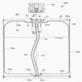
도1에 도시한 바와 같이 본 실시형태의 액체 취출 시스템(100)은, 플러그(10)(액체 취출장치)와, 내측용기(20)(제1용기)와, 외측용기(30)(제2용기)와, 소켓(40)을 구비한다. 도1은, 소켓(40)이 플러그(10)에 접속되지 않은 상태를 나타내고 있다. 또한, 도1에 도시한 액체 취출 시스템(100)은, 내측용기(20)의 내부공간(S1)과 내측용기(20)의 외부공간(S2)이 연통하고, 각각 대기압으로 되어 있는 상태를 나타낸다. 1, the
액체 취출 시스템(100)은, 소켓(40)을 통해 내측용기(20)의 내부공간(S1)에 가압용 기체를 인도하여 내부공간(S1)을 가압하고, 플러그(10)및 소켓(40)을 통해 액체(반도체제조 장치에서 이용하는 약액 등)를 외부로 취출하는 시스템이다. The
플러그(10)는, 도2에 도시한 바와 같이, 원통접촉부(11)와, 걸림돌기(12)와, 원통 가이드부(13)와, 사이펀 관(14)과, 유로부(15)와, 플랜지부(16)와, 패킹(17)(탄성부재)을 갖는다. 2, the
원통접촉부(11)와 걸림돌기(12)와 원통 가이드부(13)와 유로부(15)와 플랜지부(16)는, 수지재료 (예를 들면, HDPE(고밀도 폴리에틸렌))에 의해 일체성형된 대략 원통형상의 부재이다. The
도1에 도시한 바와 같이, 플러그(10)는 내측용기(20)의 개구부(21)에 장착된다. As shown in Fig. 1, the
플러그(10)가 갖는 원통접촉부(11)는, 내측용기(20)의 개구부(21)에 장착된 상태에서 개구부(21)의 내주면(21a)과 접촉하는 원통형상의 부재이다. The
플러그(10)가 갖는 걸림돌기(12)는, 원통접촉부(11)의 하단에 접속되는 동시에 개구부(21)의 내주면(21a)을 따라 삽입될 때에 내측으로 탄성변형되며, 개구부(21)를 통과한 후에 개구부(21)의 하단(21d) (도1참조)에 걸리는 부재이다. The
플러그(10)가 갖는 원통 가이드부(13)는, 걸림돌기(12)의 하단에 접속되는 동시에 개구부(21)의 내주면(21a)을 따라 삽입될 때에 내주면(21a)과 접촉하는 원통형상의 부재이다. 후술하는 바와 같이, 원통 가이드부(13)는, 사이펀 관(14)의 선단(14a)이 내측용기(20)의 밑면(20b)에 마련된 요부(22)에 확실하게 삽입되도록 안내하기 위한 부재이다. The
원통접촉부(11)와 걸림돌기(12)와 원통 가이드부(13)의 축선 X2둘레의 복수개소 (예를 들면, 90°마다 4개소)에는, 원통 가이드부(13)의 하단(13a)에서 원통접촉부(11)까지 축선 X2를 따라 연장되는 슬릿(미도시)이 마련되어 있다. 복수의 슬릿을 플러그(10)에 마련하는 것에 의해, 걸림돌기(12)가 개구부(21)의 내주면(21a)을 따라 삽입될 때에 걸림돌기(12)을 내측에 탄성변형시킬 수 있다. The
플러그(10)가 갖는 사이펀 관(14)은, 축선 X2방향으로 연장되는 동시에 내측용기(20)의 밑면(20b)을 향해 삽입되는 관상의 부재이다. 사이펀 관(14)은, 예를 들면, 내약품성이 우수한 PFA (4불화에틸렌과 퍼플루오르알콕시에틸렌의 공중합체)에 의해 형성되어 있다. 사이펀 관(14)은, 탄성변형이 가능한 부재로 되어 있다. The siphon
도2에 도시한 바와 같이 사이펀 관(14)은, 유로부(15)의 액체유로(15a)를 형성하는 부분을 둘러싸는 것과 같이 삽입되어 있다. 사이펀 관(14)과 유로부(15)에 형성된 에지부(15e)는, 이것들이 접촉하는 접촉 위치에 축선 X2둘레의 엔드레스 형상의 씰 영역을 형성한다. 이 씰 영역에 의해, 사이펀 관(14)의 내부와 내측용기(20)의 내부공간(S1)이 연통하지 않게 되어 있다. As shown in Fig. 2, the siphon
도2에 도시한 바와 같이, 사이펀 관(14)의 선단(14a)에는, 선단(14a)이 내측용기(20)의 요부(22)의 저부(22a)에 접촉한 상태에서 사이펀 관(14)의 내부와 요부(22)를 연통시키는 절결부(14b)가 형성되어 있다. The siphon
도1에 도시한 액체 취출 시스템(100)은, 내측용기(20)의 내부공간(S1)과 내측용기(20)의 외부공간(S2)이 연통하고, 각각 대기압인 상태를 도시한다. 이 상태에서 사이펀 관(14)은, 선단(14a)(도2참조)이 요부(22)의 저부(22a)에 접촉하여 탄성변형된 상태로 되어 있다. The
플러그(10)가 가지는 유로부(15)는, 도2에 도시한 바와 같이, 액체유로(15a)와 기체유로(15b)와 관통홀(15c)과, 밸브 조작부(15d)를 갖는다. The
액체유로(15a)는, 내측용기(20)에 수용된 액체를 사이펀 관(14)의 선단(14a)에서 관통홀(15c)로 인도하는 유로이다. The
기체유로(15b)는, 소켓(40)에 접속되는 가압용 기체의 공급원(미도시)에서 공급되는 가압용 기체를 내측용기(20)의 내부공간(S1)으로 인도하는 유로이다. 가압용 기체가 내부공간(S1)으로 인도되는 것에 의해, 사이펀 관(14)의 선단(14a)에서 액체유로(15a)를 향해 액체가 밀려나온다. 기체유로(15b)는, 축선 X2둘레의 복수개소(예를 들면, 120°씩 3개소)에 마련되어 있다. The
관통홀(15c)은, 액체유로(15a)에서 인도되는 액체를 소켓(40)의 액체유로(41a)로 인도하는 구멍이다. 관통홀(15c)은, 축선 X2둘레의 복수개소(예를 들면, 90°씩 4개소)에 마련되어 있다. The through
밸브 조작부(15d)는 플러그(10)에 소켓(40)이 장착될 때에, 소켓(40)이 가지는 밸브(43)를 축선 X2을 따라 밀어 올리는 부재이다. 소켓(40)이 갖는 밸브(43)를 밀어 올리는 것에 의해, 관통홀(15c)에서 소켓(40)의 액체유로(41a)를 향해 액체가 인도된다. The
플러그(10)가 갖는 플랜지부(16)는, 원통접촉부(11)의 상단에 접속되는 동시에 내측용기(20)의 개구부(21)의 내주면(21a)의 지름보다도 대경의 환형부재이다. The
플러그(10)가 갖는 패킹(17)은, 플랜지부(16)의 하면에 장착되는 축선 X2둘레로 연장되는 환형의 탄성부재이다. 패킹(17)은, 예를 들면, 발포폴리에틸렌이나, 내약품성이 있는 불소고무 등의 탄성체에 의해 형성되어 있다. The packing 17 of the
플러그(10)가 내측용기(20)의 개구부(21)에 장착된 상태에서, 플랜지부(16)의 하면이 패킹(17)을 통해 개구부(21)의 상단(21c)에 걸린다. 이것에 의해, 플러그(10)는, 개구부(21)에서 내부공간(S1)까지 끌려 들어가지 않게 된다. The lower surface of the
플러그(10)가 내측용기(20)의 개구부(21)에 장착된 상태에서, 개구부(21)의 상단(21c)의 둘레 전체에 걸쳐 패킹(17)이 접촉된 상태가 된다. 개구부(21)의 상단(21c)과 패킹(17)이 접촉하는 것에 의해, 축선 X2둘레로 연장되는 엔드레스 형상의 씰 영역이 형성된다. 이로 인해, 내측용기(20)의 내부공간(S1)을 가압용 기체에 의해 가압하는 경우에도, 내측용기(20)의 개구부(21)와 플러그(10)의 틈에서 가압용 기체가 외부로 새어나가는 불량을 억제할 수 있다. The packing 17 is in contact with the entire circumference of the
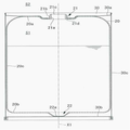
내측용기(20)는, 도3에 도시한 바와 같이, 연직방향으로 연장되는 축선 X1을 따라 원통형상으로 형성되는 용기이며, 액체를 내부에 수용 가능하게 되어 있다. 내측용기(20)는 내약품성이 있는 수지재(예를 들면, HDPE(고밀도 폴리에틸렌))에 의해 형성되어 있다. 내측용기(20)는, 상면(20a)과 밑면(20b)과 측면(20c)이 일체성형된 용기이다. As shown in Fig. 3, the
내측용기(20)의 상면(20a)의 중앙부에는, 축선 X1방향으로 연장되는 개구부(21)가 형성되어 있다. 또한, 내측용기(20)의 밑면(20b)의 중앙부에는, 요부(22)가 형성되어 있다. 이와 같이, 개구부(21)의 위치와 요부(22)의 위치는 축선 X1에 직교하는 경방향에서 일치한 위치로 되어 있다. An
개구부(21)는, 내측용기(20)의 내부공간(S1)과 외부공간(S2)과의 사이에서 액체를 유통시키는 부분으로 되어 있다. 도3에 도시한 바와 같이, 내측용기(20)의 개구부(21)의 외주면에는 수나사(2lb)가 형성되어 있다. The
수나사(2lb)에 캡(미도시)을 장착하는 것에 의해, 내부공간(S1)과 외부공간(S2)이 연통되지 않도록 하여 액체를 보관할 수 있다. 또한, 수나사(2lb)에 소켓(40)을 장착하는 것에 의해, 소켓(40)을 개구부(21)에 고정할 수 있다. By mounting a cap (not shown) on the
요부(22)는, 내측용기(20)의 내부공간(S1)에 수용되는 액체가 적어진 경우에, 액체가 고이는 부분이다. 요부(22)에 플러그(10)의 사이펀 관(14)의 선단(14a)을 삽입하는 것에 의해, 내측용기(20)에 잔액을 모으지 않고, 액체를 확실하게 취출할 수 있다. The
외측용기(30)는, 도3에 도시한 바와 같이, 연직방향으로 연장되는 축선 X1를 따라 원통형상으로 형성되는 금속제(예를 들면, 철제)의 용기이다. 외측용기(30)는, 원통형상의 측면(30c)의 하단에 밑면(30b)을 장착한 상태에서 내측용기(20)를 측면(30c)의 상단에서 삽입하고, 그 후에 측면(30c)의 상단에 상면(30a)을 장착하는 것에 의해, 내측용기(20)를 내부에 수용한다. 상면(30a)의 중앙부에는, 개구부(21)를 삽입하는 구멍이 마련되어 있다. As shown in Fig. 3, the
도3에 도시한 바와 같이, 외측용기(30)는, 개구부(21)를 외측용기(30)의 상면(30a)에서 노출하며 측면(30c)의 내주면이 내측용기(20)의 측면(20c)의 외주면과 접촉한 상태에서 내측용기(20)을 수용한다. 3, the
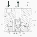
소켓(40)은, 외부의 가압용 기체의 공급원(미도시)에서 공급되는 가압용 기체를 내측용기(20)의 내부공간(S1)으로 인도하는 동시에, 내부공간(S1)의 가압에 의해 내측용기(20)로부터 취출되는 액체를 외부로 인도하는 장치이다. The
소켓(40)은, 소켓 본체(41)와, 슬리브(42)와, 밸브(43)와, O링(44)과, O링(45)을 가진다. The
소켓 본체(41)는, 축선 X1방향을 따라 대략 원통형상으로 형성되는 부재이다. The
소켓 본체(41)의 내부에는, 축선 X1방향으로 연장되는 액체유로(41a)가 형성되어 있다. 액체유로(41a)의 상단에는 내주면에 암나사가 형성된 배관 설치부(4lb)가 마련되어 있다. 배관 설치부(4lb)에는 외부로 액체를 인도하는 배관(미도시)을 장착할 수 있다. Inside the
소켓 본체(41)의 내부에는, 소켓 본체(41)를 상단에서 하단까지 관통하는 기체유로(41c)가 형성되어 있다. 기체유로(41c)의 상단에는 내주면에 암나사가 형성된 배관 설치부(41d)가 마련되어 있다. 배관 설치부(41d)에는, 외부의 공급원(미도시)에서 공급되는 가압용 기체를 플러그(10)로 인도하는 배관(미도시)을 장착할 수 있다. A
소켓 본체(41)의 액체유로(41a)의 아래쪽으로는, 밸브시트(41e)가 마련되어 있다. 도4에 도시한 바와 같이, 플러그(10)에 장착되지 않은 상태의 소켓(40)의 밸브시트(41e)에는 밸브(43)의 스프링(43c)의 부세력에 의해 밸브바디(43a)가 접촉된 상태로 되어 있다. 도4에 도시한 상태에서는, 밸브시트(41e)와 밸브바디(43a)가 접촉하는 위치가 씰 영역이 되고, 씰 영역에서 액체의 유통이 차단되게 되어 있다. A
소켓 본체(41)의 외주면에는 축선 X1둘레로 연장되는 엔드레스 형상의 환형 홈부(41f)가 형성되어 있다. 환형 홈부(41f)에는, 슬리브(42)의 환형 돌기부(42a)가 체결되어 있다. An endless
슬리브(42)는, 소켓 본체(41)을 내측용기(20)의 개구부(21)에 고정하기 위한 부재이다. 슬리브(42)는, 축선X1를 따라 원통형상으로 형성되는 부재이다. The
슬리브(42)에는, 축선 X1둘레로 연장되는 엔드레스 형상의 환형돌기부(42a)가 형성되어 있다. 도4에 도시한 바와 같이 환형돌기부(42a)는, 소켓 본체(41)에 형성된 환형 홈부(41f)와 체결되어 있다. 이로 인해, 슬리브(42)는 소켓 본체(41)에 대하여 축선 X1둘레에 상대적으로 회전가능한 상태가 된다. The
슬리브(42)의 아래 쪽의 내주면에는 암나사(42b)가 형성되어 있다. 도7에 도시한 바와 같이, 슬리브(42)의 암나사(42b)를 내측용기(20)의 개구부(21)의 외주면에 형성된 수나사(2lb)에 체결하는 것에 의해, 소켓(40)이 개구부(21)에 고정된다. A
밸브(43)는, 플러그(10)의 액체유로(15a)와 소켓(40)의 액체유로(41a)를 연통 시킬지 차단할지를 변환하는 기구이다. 밸브(43)는, 밸브바디(43a)와, 지단부(止端部)(toe of weld)(43b)와, 스프링(43c)을 갖는다. The
지단부(43b)는 외주면에 수나사가 형성된 원통형상부재이며, 소켓 본체(41)의 액체유로(41a)의 아래 쪽의 내주면에 형성된 암나사와 체결되어 있다. 지단부(43b)는 스프링(43c)의 일단을 지지하도록 되어 있다. 스프링(43c)의 타단은 밸브바디(43a)에 유지되어 있다. 이로 인해, 밸브바디(43a)에는, 스프링(43c)에 의해 축선 X1를 따라 밸브시트(41e)에 접촉하는 방향의 부세력이 가해진다. The
도7에 도시한 바와 같이 소켓(40)이 내측용기(20)의 개구부(21)에 장착된 경우, 플러그(10)의 밸브 조작부(15d)(도2참조)가 밸브바디(43a)의 선단부(43d)에 접촉하여 밸브바디(43a)를 축선 X1을 따른 위쪽으로 밀어 올린다. The
밸브바디(43a)가 위쪽으로 밀려 올라가는 것에 의해, 소켓(40)의 액체유로(41a)와 플러그(10)의 액체유로(15a)가 관통홀(15c)을 통해 연통 된 상태가 된다. The
O링(44)은, 소켓 본체(41)의 요부(41g)에 플러그(10)의 유로부(15)가 삽입된 경우에, 소켓 본체(41)와 유로부(15)의 외주면과의 사이에 씰 영역을 형성하는 탄성부재이다. The O-
O링(45)은, 소켓(40)이 내측용기(20)의 개구부(21)에 장착된 경우에, 소켓 본체(41)와 플러그(10)의 플랜지부(16)의 상단의 사이에 씰 영역을 형성하는 탄성부재이다. The O-
다음으로, 작업자가 내측용기(20)의 개구부(21)에 플러그(10)을 장착하는 공정에 대해서 설명한다. Next, a process for mounting the
본 실시형태의 액체 취출 시스템(100)을 이용하는 작업자는, 도3에 도시한 플러그(10)가 장착되지 않은 상태의 내측용기(20)의 개구부(21)에, 플러그(10)의 사이펀 관(14)의 선단(14a)을 삽입하고, 도5에 도시한 상태로 한다. 도5에 도시한 상태는, 원통 가이드부(13)의 하단(13a)을 개구부(21)의 상단(21c)에 삽입한 상태이다. An operator using the
도5에 도시한 바와 같이, 내측용기(20)의 개구부(21)의 상단(21c)에서 밑면(20b)까지의 축선 X1방향의 길이를 제1길이(L1)로 하고, 원통 가이드부(13)의 하단(13a)에서 사이펀 관(14)의 선단(14a)까지의 축선 X2방향의 길이를 제2길이(L2)로 하고 걸림돌기(12)의 하단에서 사이펀 관(14)의 선단(14a)까지의 축선 X2방향의 길이를 제3길이(L3)로 한다. 5, the length in the direction of the axis X1 from the
도5에 도시한 바와 같이, 제1길이(L1)보다도 제2길이(L2)가 짧게 되어 있다. 이로 인해, 원통 가이드부(13)의 하단(13a)을 개구부(21)에 삽입하는 시점에서 사이펀 관(14)의 선단(14a)은 내측용기(20)의 밑면(20b)의 위치(도5에 도시한 요부(22)의 상단)에 도달되지 않는다. 따라서, 사이펀 관(14)의 축선 X2를 내측용기(20)의 축선 X1에서 기울인 상태에서 사이펀 관(14)을 개구부(21)에 삽입했다 하더라도, 원통 가이드부(13)의 하단(13a)을 개구부(21)에 삽입하는 시점에서, 사이펀 관(14)의 선단(14a)을, 내측용기(20)의 밑면(20b)의 요부(22)에 확실하게 수용할 수 있는 위치에 배치할 수 있다. As shown in Fig. 5, the second length L2 is shorter than the first length L1. The
작업자는, 도5에 도시한 상태에서 더욱 플러그(10)를 축선 X1을 따라 아래 쪽으로 밀어 내리면, 도6에 도시한 상태가 된다. 도6에 도시한 상태는, 사이펀 관(14)의 선단(14a)이 요부(22)의 저부(22a)에 도달한 상태를 도시한다. When the operator further pushes the
도6에 도시한 바와 같이, 제2길이(L2)보다도 제3길이(L3)가 길게 되어 있다. 이로 인해, 사이펀 관(14)의 선단(14a)이 요부(22)의 저부(22a)에 도달한 상태에서는, 걸림돌기(12)의 하단이 개구부(21)의 상단(21c)에 도달되지 않는다. As shown in Fig. 6, the third length L3 is longer than the second length L2. The lower end of the engaging
도5에 도시한 상태에서 도6에 도시한 상태로 되는 동안에 있어서, 플러그(10)는, 원통 가이드부(13)가 개구부(21)의 내주면(21a)에 접촉한 상태가 된다. 원통 가이드부(13)에 의해 사이펀 관(14)이 축선 X1을 따라 안내되므로, 사이펀 관(14)의 선단(14a)을 내측용기(20)의 요부(22)에 확실하게 삽입하는 것이 가능해 진다. The state in which the
작업자가 도6에 도시한 상태에서 플러그(10)를 더욱 아래쪽으로 밀어 내리면, 사이펀 관(14)의 선단(14a)이 요부(22)의 저부(22a)에 접촉한 상태로 사이펀 관(14)이 탄성변형되고, 걸림돌기(12)의 하단이 개구부(21)의 상단(21c)에 도달한다. When the operator pushes the
작업자는, 걸림돌기(12)의 하단이 개구부(21)의 상단(21c)에 도달한 후에 플러그(10)를 더욱 아래 쪽으로 밀어 내리면, 걸림돌기(12)가 내측으로 탄성변형되면서 개구부(21)의 내주면(21a)을 통과한다. When the lower end of the locking
걸림돌기(12)의 상단이 개구부(21)의 내주면(21a)을 통과하고, 개구부(21)의 하단(21d)에 도달하면, 내측에 탄성변형된 걸림돌기(12)가 외측을 향해 복원된다. When the upper end of the locking
도1에 도시한 바와 같이, 개구부(21)의 내주면(21a)의 직경(D1)보다도 걸림돌기(12)의 외주면의 직경(D2)이 크게 되어 있다. 이로 인해, 걸림돌기(12)가 외측을 향해 복원된 상태에서, 걸림돌기(12)의 상단이 개구부(21)의 하단(21d)에 걸린다. 이것에 의해, 플러그(10)는, 개구부(21)의 상단(21c)에 플랜지부(16)가 걸리고 개구부(21)의 하단(21d)에 걸림돌기(12)가 걸린 상태에서, 개구부(21)에 장착된다. The diameter D2 of the outer peripheral surface of the engaging
걸림돌기(12)가 개구부(21)의 내주면(21a)을 통과할 때에, 사이펀 관(14)의 선단(14a)이 요부(22)의 저부(22a)에 접촉한 상태로 되어 있다. 이로 인해, 사이펀 관(14)이 탄성변형되나, 요부(22)에서 사이펀 관(14)의 선단(14a)이 다른 위치로 이동되지 않는다. 따라서, 도1에 도시한 바와 같이, 플러그(10)를 개구부(21)에 장착한 상태에서, 사이펀 관(14)의 선단(14a)은 요부(22)에 삽입된 상태가 된다. The
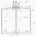
다음으로, 도7을 참조하여 내측용기(20)의 내부공간(S1)을 가압한 상태의 액체 취출 시스템(100)에 대해서 설명한다. Next, the
도7에 도시한 액체 취출 시스템(100)은, 도1에 도시한 바와 같이 내측용기(20)의 개구부(21)에 플러그(10)을 장착하고, 더욱 개구부(21)에 소켓(40)을 장착한 상태에서, 외부에서 가압용 기체를 내부공간(S1)에 도입한 상태를 나타낸다. 7, the
소켓(40)의 기체유로(41c)에 가압용 기체가 인도되면, 플러그(10)의 기체유로(15b)를 통해 내측용기(20)의 내부공간(S1)에 가압용 기체가 인도된다. 내부공간(S1)이 가압용 기체에 의해 가압되면, 수지재료에 의해 형성된 내측용기(20)가 팽창된다. The pressurizing gas is delivered to the inner space S1 of the
수지제의 내측용기(20)는 금속제의 외측용기(30)에 수용되는 동시에, 내측용기(20)의 측면(20c)의 외주면과 외측용기(30)의 측면(30c)의 내주면이 접촉한 상태로 되어 있다. 내측용기(20)는, 축선 X1에 직교하는 경방향의 팽창이 금속제의 외측용기(30)에 의해 규제되므로, 가압용 기체의 압력에 의해 축선 X1방향으로 팽창된다. The
도1에 도시한 바와 같이, 내측용기(20)의 상면(20a)과 밑면(20b)의 요부(22)의 저부(22a)는, 각각 외측용기(30)의 상면(30a)와 밑면(30b)과 접촉한다. 가압용 기체의 압력에 의해 내측용기(20)가 축선 X1방향으로 팽창하면, 외측용기(30)의 상면(30a)을 위쪽을 향해 변형시켜, 외측용기의 밑면(30b)을 아래쪽을 향해 변형시킨다. 1, the
도7에 도시한 바와 같이, 내측용기(20)가 축선 X1방향으로 팽창하고, 개구부(21)와 요부(22)의 저부(22a)까지의 거리가 길어지면, 탄성변형된 사이펀 관(14)이 서서히 복원된다. 예를 들면, 도7에 도시한 바와 같이, 사이펀 관(14)의 탄성변형이 해소되어, 사이펀 관(14)의 축선 X2가 내측용기(20)의 축선 X1과 일치된 상태가 된다. 내측용기(20)의 축선 X1방향으로 팽창하는 길이가 일정한 범위내이면, 도7에 도시한 바와 같이, 사이펀 관(14)의 선단(14a)이 요부(22)에 삽입된 상태가 된다. 이로 인해, 내측용기(20)의 내부공간(S1)을 가압한 상태에서도, 요부(22)에 잔액을 모으지 않고, 사이펀 관(14)에 의해 액체를 확실하게 취출할 수 있다. 7, when the
이상 설명한 본 실시형태가 나타내는 작용 및 효과에 대해서 설명한다. The functions and effects of the present embodiment described above will be described.
본 실시형태의 액체 취출 시스템(100)은, 상면(20a)에 축선 X1방향으로 연장되는 개구부(21)가 형성되고 밑면(20b)에 있어서의 개구부(21)와 일치하는 위치에 요부(22)가 형성된 원통형상의 내측용기(20)의 개구부(21)에 플러그(10)를 장착한 것이다. 플러그(10)를 내측용기(20)의 개구부(21)에 장착할 때에는, 원통 가이드부(13)의 하단(13a)을 개구부(21)에 삽입하고, 걸림돌기(12)를 내측으로 탄성변형시키면서 삽입하여 개구부(21)의 하단(21d)에 건다. The
본 실시형태의 액체 취출 시스템(100)은, 내측용기(20)의 개구부(21)의 상단(21c)에서 밑면(20b)까지의 축선 X1방향의 제1길이(L1)보다도 원통 가이드부(13)의 하단(13a)에서 사이펀 관(14)의 선단(14a)까지의 축선 X2방향의 제2길이(L2)가 짧다. The
이로 인해, 원통 가이드부(13)의 하단(13a)을 개구부(21)에 삽입하는 시점에서 사이펀 관(14)의 선단(14a)은 내측용기(20)의 밑면(20b)에 도달하지 않는다. 따라서, 원통 가이드부(13)의 하단(13a)을 개구부(21)에 삽입하는 시점에서, 사이펀 관(14)의 선단(14a)을, 내측용기(20)의 밑면(20b)의 요부(22)에 확실하게 수용할 수 있는 위치에 배치할 수 있다. The
또한, 원통 가이드부(13)에 의해 사이펀 관(14)이 축선 X1을 따라 안내되므로, 사이펀 관(14)의 선단(14a)을 내측용기(20)의 요부(22)에 확실하게 삽입하는 것이 가능해 진다. Since the siphon
또, 본 실시형태의 액체 취출 시스템(100)은, 제1길이(L1)보다도 걸림돌기(12)에서 사이펀 관(14)의 선단(14a)까지의 축선 X2방향의 제3길이(L3)가 길다. 이로 인해, 걸림돌기(12)가 개구부(21)의 상단(21c)을 통과하는 시점에서 사이펀 관(14)의 선단(14a)는 내측용기(20)의 요부(22)에 삽입된 상태가 된다. The
걸림돌기(12)를 개구부(21)의 상단(21c)에서 하단(21d)까지 이동시키기 위해서는, 걸림돌기(12)를 내측으로 탄성변형시키도록 플러그(10)를 밀어 넣을 필요가 있다. 이 때에, 사이펀 관(14)의 선단(14a)이 요부(22)에 삽입되어 있으므로, 플러그(10)를 밀어 넣는 동작에 의해 사이펀 관(14)의 선단(14a)이 요부(22) 이외의 장소로 이동되지 않는다. It is necessary to push the
따라서, 사이펀 관(14)의 선단(14a)이 요부(22)에 삽입된 상태에서 내측용기(20)의 개구부(21)에 플러그(10)를 장착할 수 있다. The
또한, 본 실시형태에 의하면, 플러그(10)의 유로부(15)의 기체유로(15b)를 통해 내측용기(20)의 내부공간(S1)에 가압용 기체가 인도되면, 수지제의 내측용기(20)가 팽창한다. 수지제의 내측용기(20)는 금속제의 외측용기(30)에 수용되는 동시에, 내측용기(20)의 측면(20c)의 외주면과 외측용기(30)의 측면(30c)의 내주면이 접촉된 상태가 된다. 내측용기(20)는, 축선 X1에 직교하는 경방향의 팽창이 금속제의 외측용기(30)에 의해 규제되므로, 가압용 기체의 압력에 의해 축선 X1방향으로 팽창한다. According to the present embodiment, when the pressurizing gas is delivered to the inner space S1 of the
본 실시형태에 의하면, 사이펀 관(14)의 선단(14a)이 요부(22)에 삽입된 상태에서 플러그(10)가 내측용기(20)에 장착되어 있다. 이로 인해, 내측용기(20)가 축선 X1방향으로 팽창하여 개구부(21)과 요부(22)의 저부(22a)까지의 축선 X1방향의 길이가 소정 길이만큼 길어졌다 하더라도, 소정 길이가 일정한 범위내이면, 사이펀 관(14)의 선단(14a)이 요부(22)에 삽입된 상태를 유지할 수 있다. 이로 인해, 내측용기(20)의 내부가 가압용 기체로 가압된 상태에서도, 요부(22)에 잔액을 모으지 않고 액체를 확실하게 취출할 수 있다. The
본 실시형태의 액체 취출 시스템(100)에 있어서, 사이펀 관(14)의 선단(14a)에는, 선단(14a)이 요부(22)의 저부(22a)에 접촉된 상태에서 사이펀 관(14)의 내부와 요부(22)을 연통시키는 절결부(14b)가 형성되어 있다. The
이와 같이 하는 것으로, 사이펀 관(14)의 선단(14a)이 요부(22)의 저부(22a)에 접촉된 상태에서도, 절결부(14b)를 통해 요부(22)의 액체를 사이펀 관(14)의 내부로 인도하여 취출할 수 있다. By doing so, the liquid in the
본 실시형태의 액체 취출 시스템(100)에 있어서, 플러그(10)는, 원통접촉부(11)의 상단에 접속되는 동시에 개구부(21)의 내주면(21a)의 지름보다도 대경의 플랜지부(16)을 갖는다. 그리고, 플러그(10)가 개구부(21)에 장착된 상태에서 플랜지부(16)의 하면이 개구부(21)의 상단(21c)에 걸린다. The
이와 같이 하는 것으로, 플러그(10)가 개구부(21)에 장착된 상태에서 플랜지부(16)의 하면이 개구부(21)의 상단(21c)에 걸린다. 따라서, 플러그(10)를 내측용기(20)의 개구부(21)에 확실하게 고정할 수 있다. The lower surface of the
본 실시형태의 액체 취출 시스템(100)에 있어서, 플랜지부(16)의 하면에는 축선 X1둘레로 연장되는 엔드레스 형상의 패킹(17)이 장착되어 있다. In the liquid take-out
이와 같이 하는 것으로, 플랜지부(16)의 하면과 개구부(21)의 상단이 접촉하는 위치에 축선 X1둘레로 연장되는 엔드레스 형상의 씰 영역이 형성된다. 이로 인해, 내측용기(20)의 내부공간(S1)을 가압용 기체에 의해 가압하는 경우에도, 내측용기(20)의 개구부(21)와 플러그(10)의 틈에서 가압용 기체가 외부에 새어나가는 불량을 억제할 수 있다. In this manner, an endless seal area extending around the axial line X1 is formed at a position where the lower surface of the
〔다른 실시형태〕 [Other Embodiments]
이상의 설명에 있어서, 내측용기(20)의 개구부(21)및 요부(22)는, 내측용기(20)의 중앙부(중심축인 축선 X1이 통과하는 위치)에 형성되는 것으로 하였으나, 다른 태양일 수 있다. The
예를 들면, 개구부(21)및 요부(22)는, 중앙부 이외의 다른 위치에 형성되도록 할 수 있다. 이 경우, 내측용기(20)의 밑면(20b)에 형성되는 요부(22)의 위치는, 내측용기(20)의 상면(20a)에 형성되는 개구부(21)의 위치와 일치시키는 것으로 한다. For example, the
그 외, 본 발명은 상술한 실시형태에 한정되지 않으며, 그 요지를 일탈하지 않는 범위 내에서 적절히 변경할 수 있다. In addition, the present invention is not limited to the above-described embodiment, and can be appropriately changed within the scope not deviating from the gist of the present invention.
100: 액체 취출 시스템
10: 플러그(액체 취출장치)
20: 내측용기(제1용기)
30: 외측용기(제2용기)
40: 소켓100: liquid extraction system
10: Plug (liquid take-out device)
20: inner container (first container)
30: outer container (second container)
40: Socket
Claims (7)
상기 개구부에 장착되는 액체 취출장치를 구비하고,
상기 액체 취출장치는,
상기 개구부에 장착된 상태에서 상기 개구부의 내주면과 접촉하는 원통형상의 원통접촉부와,
상기 원통접촉부의 하단에 접속되는 동시에 상기 개구부의 내주면을 따라 삽입될 때에 내측으로 탄성변형되고 상기 개구부를 통과한 후에 상기 개구부의 하단에 걸리는 걸림돌기와,
상기 걸림돌기의 하단에 접속되는 동시에 상기 개구부의 내주면을 따라 삽입될 때에 상기 내주면과 접촉하는 원통형상의 원통 가이드부와,
제2축선 방향으로 연장되는 동시에 상기 제1용기의 상기 밑면을 향해 삽입되는 사이펀 관과,
상기 사이펀 관에 연결되는 액체유로와 상기 제1용기의 외부에서 공급되는 가압용 기체를 상기 제1용기의 내부 공간으로 인도하는 기체유로가 형성된 유로부를 가지며,
상기 제1용기의 상기 개구부의 상단에서 상기 밑면까지의 상기 제1축선 방향의 제1길이보다도 상기 원통 가이드부의 하단에서 상기 사이펀 관의 선단까지의 상기 제2축선 방향의 제2길이가 짧고, 상기 제1길이보다도 상기 걸림돌기에서 상기 사이펀 관의 선단까지의 상기 제2축선 방향의 제3길이가 긴 액체 취출 시스템. A first container formed in a cylindrical shape along a first axis extending in a vertical direction and having an opening extending in the first axial direction on an upper surface thereof and having a concave portion formed at a position coinciding with the opening in the bottom surface;
And a liquid take-out device mounted on the opening,
The liquid take-
A cylindrical cylindrical contact portion which is in contact with the inner peripheral surface of the opening portion in a state of being mounted on the opening portion,
A latching protrusion connected to a lower end of the cylindrical contact portion and elastically deformed inward when inserted along the inner circumferential surface of the opening portion and hooked to a lower end of the opening portion after passing through the opening portion;
A cylindrical cylindrical guide portion connected to a lower end of the locking projection and contacting with the inner peripheral surface when inserted along the inner peripheral surface of the opening portion,
A siphon tube extending in a second axial direction and inserted toward the bottom surface of the first container,
And a gas flow path for guiding a pressurizing gas supplied from the outside of the first container to the inner space of the first container is formed,
The second length in the second axial direction from the lower end of the cylindrical guide portion to the tip of the siphon tube is shorter than the first axial length in the first axial direction from the upper end of the opening portion of the first container to the lower surface, And the third length in the second axial direction from the locking projection to the distal end of the siphon tube is longer than the first length.
상기 제1축선 방향을 따라 원통형상으로 형성되는 동시에 상기 개구부를 노출하며, 내주면이 상기 제1용기의 외주면과 접촉된 상태에서 상기 제1용기를 수용하는 제2용기를 구비하고,
상기 제1용기는 수지제이며 상기 제2용기는 금속제인 액체 취출 시스템. The method according to claim 1,
And a second container which is formed in a cylindrical shape along the first axial direction and exposes the opening portion and accommodates the first container in a state in which the inner peripheral surface thereof is in contact with the outer peripheral surface of the first container,
Wherein the first container is made of resin and the second container is made of metal.
상기 개구부에 장착된 상태에서 상기 개구부의 내주면과 접촉하는 원통형상의 원통접촉부와,
상기 원통접촉부의 하단에 접속되는 동시에 상기 개구부의 내주면을 따라 삽입될 때에 내측으로 탄성변형되고, 상기 개구부를 통과한 후에 상기 개구부의 하단에 걸리는 걸림돌기와,
상기 걸림돌기의 하단에 접속되는 동시에 상기 개구부의 내주면을 따라 삽입될 때에 상기 내주면과 접촉하는 원통형상의 원통 가이드부와,
제2축선 방향으로 연장되는 동시에 상기 제1용기의 상기 밑면을 향해 삽입되는 사이펀 관과,
상기 사이펀 관에 연결되는 액체유로와 상기 제1용기의 외부에서 공급되는 가압용 기체를 상기 제1용기의 내부공간으로 인도하는 기체유로가 형성된 유로부를 가지며,
상기 제1용기의 상기 개구부의 상단에서 상기 밑면까지의 상기 제1축선 방향의 제1길이보다도 상기 원통 가이드부의 하단에서 상기 사이펀 관의 선단까지의 상기 제2축선 방향의 제2길이가 짧고, 상기 제1길이보다도 상기 걸림돌기에서 상기 사이펀 관의 선단까지의 상기 제2축선 방향의 제3길이가 긴 액체 취출장치. The first container is formed in a cylindrical shape along a first axis extending in the vertical direction and is formed with an opening extending in the first axial direction on the upper surface thereof and mounted on the first container in which the concave portion is formed at a position coinciding with the opening in the bottom surface A liquid take-
A cylindrical cylindrical contact portion which is in contact with the inner peripheral surface of the opening portion in a state of being mounted on the opening portion,
A latching protrusion connected to a lower end of the cylindrical contact portion and elastically deformed inward when inserted along the inner circumferential surface of the opening portion and engaged with a lower end of the opening portion after passing through the opening portion,
A cylindrical cylindrical guide portion connected to a lower end of the locking projection and contacting with the inner peripheral surface when inserted along the inner peripheral surface of the opening portion,
A siphon tube extending in a second axial direction and inserted toward the bottom surface of the first container,
And a gas flow path for guiding a pressurizing gas supplied from the outside of the first container to the inner space of the first container is formed,
The second length in the second axial direction from the lower end of the cylindrical guide portion to the front end of the siphon tube is shorter than the first axial length in the first axial direction from the upper end of the opening portion of the first container to the lower surface, And the third length in the second axial direction from the locking projection to the distal end of the siphon tube is longer than the first length.
상기 제1용기는, 상기 제1축선 방향을 따라 원통형상으로 형성되는 제2용기에, 상기 개구부가 노출되며 외주면이 상기 제2용기의 내주면과 접촉된 상태에서 수용되어 있고,
상기 제1용기는 수지제이며 상기 제2용기는 금속제인 액체 취출장치. 4. The method of claim 3,
Wherein the first container is accommodated in a second container formed in a cylindrical shape along the first axial line direction so that the opening is exposed and the outer peripheral surface is in contact with the inner peripheral surface of the second container,
Wherein the first container is made of resin and the second container is made of metal.
상기 사이펀 관의 선단에는, 상기 선단이 상기 요부의 저부에 접촉된 상태에서 상기 사이펀 관의 내부와 상기 요부를 연통 시키는 절결부가 형성되어 있는 액체 취출장치. The method according to claim 3 or 4,
Wherein a tip portion of the siphon tube is provided with a cutout portion for communicating the inside of the siphon tube with the recessed portion in a state where the tip is in contact with the bottom of the recessed portion.
상기 원통접촉부의 상단에 접속되는 동시에 상기 개구부의 내주면의 지름보다도 대경의 플랜지부를 가지며,
상기 개구부에 장착된 상태에서 상기 플랜지부의 하면이 상기 개구부의 상단에 걸리는 액체 취출장치. The method according to claim 3 or 4,
And a flange portion connected to an upper end of the cylindrical contact portion and having a larger diameter than an inner peripheral surface of the opening portion,
And a lower surface of the flange portion is engaged with an upper end of the opening portion in a state where the flange portion is mounted on the opening portion.
상기 플랜지부의 하면에는 상기 제2축선 둘레로 연장되는 엔드레스 형상의 탄성부재가 장착되어 있는 액체 취출장치.
The method according to claim 6,
And an endless elastic member extending around the second axis is mounted on a lower surface of the flange portion.
Applications Claiming Priority (2)
| Application Number | Priority Date | Filing Date | Title |
|---|---|---|---|
| JP2014238772A JP6486666B2 (en) | 2014-11-26 | 2014-11-26 | Liquid take-out system and liquid take-out device |
| JPJP-P-2014-238772 | 2014-11-26 |
Publications (2)
| Publication Number | Publication Date |
|---|---|
| KR20160063243A true KR20160063243A (en) | 2016-06-03 |
| KR102536124B1 KR102536124B1 (en) | 2023-05-23 |
Family
ID=54557282
Family Applications (1)
| Application Number | Title | Priority Date | Filing Date |
|---|---|---|---|
| KR1020150158876A Active KR102536124B1 (en) | 2014-11-26 | 2015-11-12 | Liquid withdrawing system and liquid withdrawing device |
Country Status (4)
| Country | Link |
|---|---|
| US (1) | US20160146391A1 (en) |
| EP (1) | EP3026008B1 (en) |
| JP (1) | JP6486666B2 (en) |
| KR (1) | KR102536124B1 (en) |
Families Citing this family (6)
| Publication number | Priority date | Publication date | Assignee | Title |
|---|---|---|---|---|
| BR112018008530A2 (en) * | 2015-11-25 | 2018-10-30 | United Technologies Corp | pressure vessel set |
| CN109094925A (en) * | 2017-06-20 | 2018-12-28 | 瀚宇彩晶股份有限公司 | Liquid containing barrel |
| GB2568062B (en) * | 2017-11-02 | 2021-05-05 | Packaging Innovation Ltd | A container |
| IT201800006011A1 (en) * | 2018-06-04 | 2019-12-04 | THREADED ADAPTER FOR RAPID EMPTYING OF BARRELS / BINS CONTAINING LIQUIDS | |
| WO2019234515A1 (en) * | 2018-06-04 | 2019-12-12 | Tagliareni Daniele | Threaded adaptor for the rapid emptying of barrels/bins containing a liquid |
| JP7264429B2 (en) * | 2018-12-21 | 2023-04-25 | テクノアート有限会社 | beverage container |
Citations (8)
| Publication number | Priority date | Publication date | Assignee | Title |
|---|---|---|---|---|
| JPH0540200U (en) * | 1991-10-29 | 1993-05-28 | 麒麟麦酒株式会社 | Liquid pouring device |
| US5299608A (en) * | 1992-03-16 | 1994-04-05 | The Hoover Company | Sealed coupling for a fluid container |
| JP2005528293A (en) * | 2002-04-23 | 2005-09-22 | マウザー−ヴェルケ ゲゼルシャフト ミット ベシュレンクテル ハフツング ウント コンパニー コマンディートゲゼルシャフト | Plastic container |
| JP2009173292A (en) | 2008-01-21 | 2009-08-06 | Surpass Kogyo Kk | Connector for liquid tank |
| US20090230132A1 (en) * | 2006-06-28 | 2009-09-17 | Tokyo Ohka Kogyo Co., Ltd. | Fluid container and fluid-containing container using the same |
| US20110108580A1 (en) * | 2009-11-12 | 2011-05-12 | Koh Teng Hwee | Pump |
| JP2011121645A (en) * | 2009-11-16 | 2011-06-23 | Sekisui Seikei Ltd | Resin container and composite container, and manufacturing method for resin container |
| JP2013091515A (en) * | 2011-10-27 | 2013-05-16 | Kodama Jushi Kogyo Kk | Resin container |
Family Cites Families (17)
| Publication number | Priority date | Publication date | Assignee | Title |
|---|---|---|---|---|
| US2969161A (en) * | 1958-03-24 | 1961-01-24 | Ceeco Products Pty Ltd | Bung for beer barrels and the like |
| US3129730A (en) * | 1961-07-14 | 1964-04-21 | John F Simon | Tapping system for liquid container or the like |
| US3371825A (en) * | 1966-05-12 | 1968-03-05 | Multiform Desiccant Products I | Sorptive getter for pressure discharge dispensers |
| US3698417A (en) * | 1970-03-11 | 1972-10-17 | Republic Corp | Keg tapping device with automatic gas shutoff valve |
| GB2101090B (en) * | 1979-02-28 | 1983-08-17 | Cadbury Schweppes Ltd | Dispensing container |
| US4470526A (en) * | 1981-08-10 | 1984-09-11 | Jungkeun Cha | Siphon dispensing bottle |
| JPS60163271U (en) * | 1983-11-11 | 1985-10-30 | 東京コカコ−ラボトリング株式会社 | Liquid storage and distribution container |
| US4694975A (en) * | 1984-05-10 | 1987-09-22 | Mckesson Corporation | Method and apparatus for storing and dispensing fluids containered under gas pressure |
| IT1254482B (en) * | 1992-02-28 | 1995-09-25 | Sar Spa | SPRAY BOTTLE WITH OPERABLE PUMP FOR CRUSHING ITSELF |
| US5335821A (en) * | 1992-09-11 | 1994-08-09 | Now Technologies, Inc. | Liquid chemical container and dispensing system |
| PT977702E (en) * | 1997-04-25 | 2002-04-29 | Riedel De Haen Gmbh | CONTAINER CLOSURE |
| JPH1142697A (en) * | 1997-07-25 | 1999-02-16 | Dainippon Printing Co Ltd | Blow molding method and apparatus and blow molded container |
| US6109480A (en) * | 1998-07-27 | 2000-08-29 | Ecolab Inc. | Liquid dispenser and docking station for mating container |
| EP1760385B1 (en) * | 2004-06-01 | 2015-05-06 | Surpass Industry Co., Ltd. | Connector to be attached to liquid tank and liquid tank provided with the connector |
| JP5607360B2 (en) * | 2007-06-25 | 2014-10-15 | サーパス工業株式会社 | Plug structure and plug / socket structure |
| JP5454849B2 (en) * | 2008-12-25 | 2014-03-26 | 株式会社吉野工業所 | Container body for pump |
| JP5462012B2 (en) * | 2010-02-03 | 2014-04-02 | サーパス工業株式会社 | Siphon tube structure |
-
2014
- 2014-11-26 JP JP2014238772A patent/JP6486666B2/en active Active
-
2015
- 2015-11-12 KR KR1020150158876A patent/KR102536124B1/en active Active
- 2015-11-13 EP EP15194584.7A patent/EP3026008B1/en active Active
- 2015-11-18 US US14/944,646 patent/US20160146391A1/en not_active Abandoned
Patent Citations (8)
| Publication number | Priority date | Publication date | Assignee | Title |
|---|---|---|---|---|
| JPH0540200U (en) * | 1991-10-29 | 1993-05-28 | 麒麟麦酒株式会社 | Liquid pouring device |
| US5299608A (en) * | 1992-03-16 | 1994-04-05 | The Hoover Company | Sealed coupling for a fluid container |
| JP2005528293A (en) * | 2002-04-23 | 2005-09-22 | マウザー−ヴェルケ ゲゼルシャフト ミット ベシュレンクテル ハフツング ウント コンパニー コマンディートゲゼルシャフト | Plastic container |
| US20090230132A1 (en) * | 2006-06-28 | 2009-09-17 | Tokyo Ohka Kogyo Co., Ltd. | Fluid container and fluid-containing container using the same |
| JP2009173292A (en) | 2008-01-21 | 2009-08-06 | Surpass Kogyo Kk | Connector for liquid tank |
| US20110108580A1 (en) * | 2009-11-12 | 2011-05-12 | Koh Teng Hwee | Pump |
| JP2011121645A (en) * | 2009-11-16 | 2011-06-23 | Sekisui Seikei Ltd | Resin container and composite container, and manufacturing method for resin container |
| JP2013091515A (en) * | 2011-10-27 | 2013-05-16 | Kodama Jushi Kogyo Kk | Resin container |
Also Published As
| Publication number | Publication date |
|---|---|
| EP3026008B1 (en) | 2018-06-27 |
| US20160146391A1 (en) | 2016-05-26 |
| KR102536124B1 (en) | 2023-05-23 |
| EP3026008A1 (en) | 2016-06-01 |
| JP6486666B2 (en) | 2019-03-20 |
| JP2016098032A (en) | 2016-05-30 |
Similar Documents
| Publication | Publication Date | Title |
|---|---|---|
| KR20160063243A (en) | Liquid withdrawing system and liquid withdrawing device | |
| KR101585423B1 (en) | Pipe joint | |
| US7677608B2 (en) | Quick connector | |
| US6568427B2 (en) | Connector for fluid container | |
| EP3324096B1 (en) | Filling device | |
| EP4023929B1 (en) | Filling device | |
| CN101878390A (en) | Tube connection systems for pressurized fluid systems | |
| CN102444757A (en) | Connecting element for a fluid connection | |
| WO2016031726A1 (en) | Valve case mounting structure | |
| US9517925B2 (en) | Valve-integrating container, liquid withdrawing device equipped with the same, and method for manufacturing valve-integrating container | |
| KR101366473B1 (en) | Connector for liquid tank | |
| EP3719381B1 (en) | Filling device | |
| JP4986520B2 (en) | Coupling device for fluid transfer | |
| US6505863B2 (en) | Connector | |
| US20190040987A1 (en) | A domestic appliance system with push-fit fluid coupling | |
| JP2016098032A5 (en) | ||
| KR20240134158A (en) | Container connection system and fluid container | |
| JP7450450B2 (en) | Discharge container | |
| JP2008001253A (en) | Bent tube | |
| KR101634506B1 (en) | one touch style pipe coupling device | |
| JP4072291B2 (en) | Chemical tank connection structure | |
| JP7004998B2 (en) | Plugs and connectors | |
| JP2007127265A (en) | Fluid supplying system and fluid coupling | |
| JP2026511980A (en) | Plug connector | |
| JP2011011795A (en) | Liquid take-out device |
Legal Events
| Date | Code | Title | Description |
|---|---|---|---|
| PA0109 | Patent application |
Patent event code: PA01091R01D Comment text: Patent Application Patent event date: 20151112 |
|
| PG1501 | Laying open of application | ||
| A201 | Request for examination | ||
| PA0201 | Request for examination |
Patent event code: PA02012R01D Patent event date: 20201006 Comment text: Request for Examination of Application Patent event code: PA02011R01I Patent event date: 20151112 Comment text: Patent Application |
|
| E902 | Notification of reason for refusal | ||
| PE0902 | Notice of grounds for rejection |
Comment text: Notification of reason for refusal Patent event date: 20220506 Patent event code: PE09021S01D |
|
| E90F | Notification of reason for final refusal | ||
| PE0902 | Notice of grounds for rejection |
Comment text: Final Notice of Reason for Refusal Patent event date: 20221122 Patent event code: PE09021S02D |
|
| E701 | Decision to grant or registration of patent right | ||
| PE0701 | Decision of registration |
Patent event code: PE07011S01D Comment text: Decision to Grant Registration Patent event date: 20230512 |
|
| GRNT | Written decision to grant | ||
| PR0701 | Registration of establishment |
Comment text: Registration of Establishment Patent event date: 20230519 Patent event code: PR07011E01D |
|
| PR1002 | Payment of registration fee |
Payment date: 20230519 End annual number: 3 Start annual number: 1 |
|
| PG1601 | Publication of registration |