KR20160056771A - Method and apparatus for requesting uplink resource allocation - Google Patents
Method and apparatus for requesting uplink resource allocation Download PDFInfo
- Publication number
- KR20160056771A KR20160056771A KR1020150079463A KR20150079463A KR20160056771A KR 20160056771 A KR20160056771 A KR 20160056771A KR 1020150079463 A KR1020150079463 A KR 1020150079463A KR 20150079463 A KR20150079463 A KR 20150079463A KR 20160056771 A KR20160056771 A KR 20160056771A
- Authority
- KR
- South Korea
- Prior art keywords
- resource allocation
- base station
- information
- uplink
- terminal
- Prior art date
Links
Images


Classifications
-
- H04W72/0413—
-
- H04W72/14—
Abstract
The UE allocates a resource for transmitting at least one scheduling request indicating a resource amount of data to be transmitted from the BS and transmits the at least one scheduling request indicating the amount of resources required for transmission of the data to the BS.
Description
The present invention relates to a method and apparatus for requesting uplink resource allocation, and more particularly, to a method and apparatus for requesting uplink resource allocation for a service requiring a short transmission delay.
Long Term Evolution (LTE) systems are designed to meet the data traffic transmission delay requirement of 10ms or less, but depending on various conditions such as system load condition, packet size, and channel condition, actual data transmission experiences a longer transmission delay do. Also, the delay time from the uplink to the data transmission is variable depending on the connection with the base station of the UE and the uplink resource allocation state.
In a conventional LTE (Long Term Evolution) / LTE-A (LTE Advanced) system, when a UE needs allocation of resources for uplink data transmission to a base station, the UE determines whether uplink synchronization is maintained, Or requests an uplink resource allocation to a base station using a random access procedure or an already allocated Physical Uplink Control Channel or a Physical Uplink Shared Channel.
If there is no uplink shared channel allocated to the UE and only the uplink control channel is allocated, the UE transmits a Scheduling Request (SR) through the allocated uplink control channel to inform the BS of the necessity of resource allocation . However, the SR indicates that the UE has data to be transmitted, but does not include other information on the data to be transmitted by the UE. Therefore, the base station receiving the SR only allocates resources of a fixed size to the terminal that transmitted the SR.
The MS transmits a buffer status report (BSR) to the BS using uplink resources allocated from the BS.
After receiving the BSR from the terminal, the base station can check the buffer status information of the terminal and allocate resources to the terminal using the buffer status information.
In the uplink resource allocation procedure through the SR and BSR transmission of the existing LTE / LTE-A system, a delay time of data transmission occurs due to the SR allocation period of the UE and additional transmission of the BSR thereafter. A delay time of 20.5 ms occurs from SR transmission to uplink data transmission even if a minimum value of the SR allocation period is 1 ms and a processing time is 3 ms and there is no transmission error. This is not only larger than 10ms, which is a requirement for LTE data traffic transmission delay, but also requires increased transmission capacity and radio range delay reduction technology compared to 4G mobile communication so that people / objects / information can be connected at any time and anywhere organically. It is not suitable for 4G or later mobile communication.
SUMMARY OF THE INVENTION It is an object of the present invention to provide an uplink resource allocation requesting method and apparatus which can reduce a delay time required for performing a procedure of requesting resource allocation in an uplink and allocating resources from a base station.
According to an embodiment of the present invention, a method is provided in which a terminal requests an uplink resource allocation to a base station. A method for requesting an uplink resource allocation comprises the steps of: allocating, from a base station, a resource for transmitting at least one scheduling request indicating a resource amount of data to be transmitted; and transmitting the at least one scheduling request To the base station.
According to the embodiment of the present invention, it is possible to reduce a delay time required to perform a procedure for requesting resource allocation in an uplink and allocating resources from a base station, and it is possible to support a low-delay service between a base station and a terminal.
FIG. 1 is a diagram illustrating an uplink resource request and allocation procedure when only a PUCCH is allocated in a state where a terminal is registered in a base station in an LTE / LTE-A system.
2 is a diagram illustrating an uplink resource allocation request and an uplink allocation procedure in a mobile communication system according to an embodiment of the present invention.
3 is a diagram illustrating a resource allocation method for SR transmission in the uplink resource allocation procedure shown in FIG.
FIGS. 4, 5, and 6 are diagrams illustrating a method of allocating resources for a plurality of SR allocation and transmission according to an embodiment of the present invention. Referring to FIG.
7 is a flowchart illustrating an uplink resource allocation request method of a UE according to an embodiment of the present invention.
8 is a diagram illustrating an uplink resource allocation apparatus according to an embodiment of the present invention.
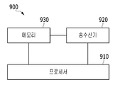
9 is a diagram illustrating an apparatus for requesting uplink resource allocation according to an embodiment of the present invention.
Hereinafter, embodiments of the present invention will be described in detail with reference to the accompanying drawings so that those skilled in the art can easily carry out the present invention. The present invention may, however, be embodied in many different forms and should not be construed as limited to the embodiments set forth herein. In order to clearly illustrate the present invention, parts not related to the description are omitted, and similar parts are denoted by like reference characters throughout the specification.
Throughout the specification and claims, when a section is referred to as "including " an element, it is understood that it does not exclude other elements, but may include other elements, unless specifically stated otherwise.
Throughout the specification, a terminal is referred to as a mobile terminal (MT), a mobile station (MS), an advanced mobile station (AMS), a high reliability mobile station (HR- A subscriber station (SS), a portable subscriber station (PSS), an access terminal (AT), a user equipment (UE) , HR-MS, SS, PSS, AT, UE, and the like.
Also, a base station (BS) is an advanced base station (ABS), a high reliability base station (HR-BS), a node B, an evolved node B, eNodeB), an access point (AP), a radio access station (RAS), a base transceiver station (BTS), a mobile multihop relay (MMR) (RS), a relay node (RN) serving as a base station, an advanced relay station (ARS) serving as a base station, a high reliability relay station (HR) A femto BS, a home Node B, a HNB, a pico BS, a metro BS, a micro BS, ), Etc., and may be all or part of an ABS, a Node B, an eNodeB, an AP, a RAS, a BTS, an MMR-BS, an RS, an RN, an ARS, It may include a negative feature.
Now, a method and apparatus for requesting an uplink resource allocation according to an embodiment of the present invention will be described in detail with reference to the drawings.
FIG. 1 is a diagram illustrating an uplink resource request and allocation procedure when only a PUCCH is allocated in a state where a terminal is registered in a base station in an LTE / LTE-A system.
In the existing LTE / LTE-A system, the resource request and resource allocation procedure for data transmission in the uplink varies depending on the connection status of the
The uplink resource allocation procedure shown in FIG. 1 is performed in a state (RRC_CONNECTED) where there is an active connection between the
Referring to FIG. 1, the MS 100 transmits a scheduling request (SR) through an allocated PUCCH in order to request an uplink resource allocation for data transmission to the BS 200 (S110). The SR is used to indicate that there is data to be transmitted by the UE, and has a value of 1 bit indicating whether resource allocation is necessary.
Upon receiving the SR from the
The
When the UE 100 can not transmit all the data to be transmitted by the UL resource, the UE 100 requests UL resource allocation to the
The
The
1, the delay time from transmission of the SR to transmission of the uplink data through the BSR transmission procedure depends on the period of the SR allocated to the
In order to support low-delay services requiring a minimum transmission delay in the radio section, the delay time required for uplink data transmission through the additional transmission procedure of the BSR after the SR transmission is reduced, Will be described in detail with reference to FIG.
2 is a diagram illustrating an uplink resource allocation request and an uplink allocation procedure in a mobile communication system according to an embodiment of the present invention.
2, the MS 100 includes information on a BSR corresponding to information on a resource allocation requested by the MS 100 to the SR in the SR, and transmits an SR including information on the BSR to the BS 200 (S210). SR has a value of 1 bit. The
The
The MS 100 transmits uplink data using uplink resources allocated through UL grant (S230).
That is, in the existing LTE / LTE-A system, the MS 100 transmits 1-bit information to the BS through a resource (PUCCH) capable of transmitting an SR allocated with a predetermined periodic value. The 1-bit information can indicate only the necessity of resource allocation and can not transmit information on the resource requested to the
A method of transmitting BSR information through a plurality of SR assignments will be described below.
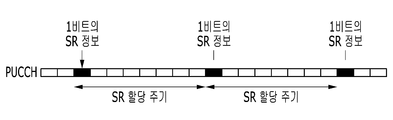
3 is a diagram illustrating a resource allocation method for SR transmission in the uplink resource allocation procedure shown in FIG.
Referring to FIG. 3, the
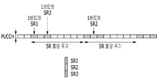
FIGS. 4, 5, and 6 are diagrams illustrating a method of allocating resources for a plurality of SR allocation and transmission according to an embodiment of the present invention. Referring to FIG. At this time, each SR uses the PUCCH format 1 of the PUCCH transmission format for transmitting 1-bit information in the same manner as in FIG.
As shown in FIG. 4, the
The
As shown in FIG. 5, the
The
The resource allocation method of FIGS. 4 and 5 can minimize the influence on the LTE system standard since the SR allocation period for each UE can be the same value as that of the existing (for example, FIG. 1).
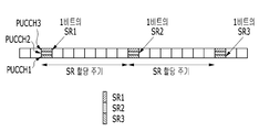
Also, as shown in FIG. 6, the
The
In the resource allocation method shown in FIG. 6, the SR related overhead of the LTE system is maintained at the same level, while the delay decreasing performance may be variable according to the SR allocation period value.
Meanwhile, the terminal 100 and the
According to another embodiment of the present invention, the
In case of transmitting N-bit SR using PUCCH format 2 or PUCCH format 3 instead of PUCCH format 1, the terminal 100 may be configured to use an extended (shortened) BSR, A new N-bit SR can be constructed to convey the information of the BSR. First, a new N-bit SR is a 1-bit D [dynamic (one time request)] / S (1), which is information indicating whether the resource request of the
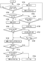
7 is a flowchart illustrating an uplink resource allocation request method of a UE according to an embodiment of the present invention.
Referring to FIG. 7, if there is data to be transmitted to the buffer in the terminal 100 (S702), the terminal 100 checks whether there is an allocated PUSCH (S704). If there is a PUSCH allocated to the terminal 100, it is confirmed whether the allocated PUSCH is enough to transmit data (S724).
If the PUSCH is allocated to the terminal 100, the terminal 100 transmits the data using the assigned PUSCH (S730).
Meanwhile, if the allocated PUSCH is not enough to transmit data, the terminal 100 triggers the BSR (S726). The
On the other hand, if there is no PUSCH allocated to the terminal 100, the terminal 100 triggers the BSR (S706). When the BSR is triggered, the terminal 100 checks whether there is a PUCCH resource allocated in advance (S708). If there is no PUCCH resource allocated in advance, the terminal 100 performs a random access procedure (S722).
Meanwhile, if there is an allocated PUCCH resource, the
In step S712, the
The
When the PUSCH resource allocation is performed in the
8 is a diagram illustrating an uplink resource allocation apparatus according to an embodiment of the present invention.
8, the uplink
The
The
The
The
9 is a diagram illustrating an apparatus for requesting uplink resource allocation according to an embodiment of the present invention.
9, the uplink resource
The
The
The
The
The embodiments of the present invention are not limited to the above-described apparatuses and / or methods, but may be implemented through a program for realizing functions corresponding to the configuration of the embodiment of the present invention or a recording medium on which the program is recorded, Such an embodiment can be readily implemented by those skilled in the art from the description of the embodiments described above.
While the present invention has been particularly shown and described with reference to exemplary embodiments thereof, it is to be understood that the invention is not limited to the disclosed exemplary embodiments, It belongs to the scope of right.
Claims (1)
Allocating, from a base station, a resource for transmitting at least one scheduling request indicating a resource amount of data to be transmitted; and
Transmitting the at least one scheduling request indicating the amount of resources required for transmission of the data to the base station
And transmitting the uplink resource allocation request message.
Applications Claiming Priority (2)
| Application Number | Priority Date | Filing Date | Title |
|---|---|---|---|
| KR20140156380 | 2014-11-11 | ||
| KR1020140156380 | 2014-11-11 |
Publications (1)
| Publication Number | Publication Date |
|---|---|
| KR20160056771A true KR20160056771A (en) | 2016-05-20 |
Family
ID=56103869
Family Applications (1)
| Application Number | Title | Priority Date | Filing Date |
|---|---|---|---|
| KR1020150079463A KR20160056771A (en) | 2014-11-11 | 2015-06-04 | Method and apparatus for requesting uplink resource allocation |
Country Status (1)
| Country | Link |
|---|---|
| KR (1) | KR20160056771A (en) |
Cited By (3)
| Publication number | Priority date | Publication date | Assignee | Title |
|---|---|---|---|---|
| KR20170000776A (en) * | 2015-06-23 | 2017-01-03 | 한국전자통신연구원 | Method and for apparatus for transmitting data in direct device to device communication |
| WO2019015157A1 (en) * | 2017-07-18 | 2019-01-24 | 华为技术有限公司 | Data transmission method and apparatus |
| WO2022255680A1 (en) * | 2021-06-01 | 2022-12-08 | 삼성전자 주식회사 | Method for transmitting contention-based data in non-terrestrial-network-based communication system, and electronic device for performing same |
-
2015
- 2015-06-04 KR KR1020150079463A patent/KR20160056771A/en unknown
Cited By (4)
| Publication number | Priority date | Publication date | Assignee | Title |
|---|---|---|---|---|
| KR20170000776A (en) * | 2015-06-23 | 2017-01-03 | 한국전자통신연구원 | Method and for apparatus for transmitting data in direct device to device communication |
| WO2019015157A1 (en) * | 2017-07-18 | 2019-01-24 | 华为技术有限公司 | Data transmission method and apparatus |
| US11134378B2 (en) | 2017-07-18 | 2021-09-28 | Huawei Technologies Co., Ltd. | Data transmission method and apparatus |
| WO2022255680A1 (en) * | 2021-06-01 | 2022-12-08 | 삼성전자 주식회사 | Method for transmitting contention-based data in non-terrestrial-network-based communication system, and electronic device for performing same |
Similar Documents
| Publication | Publication Date | Title |
|---|---|---|
| US10986662B2 (en) | Conditional uplink radio resource utilization in a cellular network | |
| US10652923B2 (en) | Method for indicating the allocated resources for a HARQ message in a random access procedure for a low-complexity, narrowband terminal | |
| US20190159236A1 (en) | Resource scheduling method and apparatus | |
| CN110945945B (en) | Radio Resource Control (RRC) messages for enhanced scheduling requests | |
| TWI521996B (en) | Method and apparatus for selecting and reselecting an uplink primary carrier | |
| US9572139B2 (en) | Contention based transmission and collision avoidance | |
| CN107113756B (en) | Scheduling assignment transmission timing for user equipment supporting device-to-device communication | |
| EP3869719B1 (en) | Method and device for transmitting uplink control information | |
| WO2015114952A1 (en) | Base station, transmission method, mobile station, and retransmission control method | |
| US11297614B2 (en) | Collision avoidance for uplink radio resource allocation in reoccurring time intervals | |
| KR20220037492A (en) | Method and apparatus for sidelink transmission in a wireless communication system | |
| US20220232618A1 (en) | Methods, communications devices, and infrastructure equipment | |
| JP2022084639A (en) | Communication device and method in wireless network | |
| US10587493B2 (en) | Device to device discovery resource allocation | |
| JP2023065547A (en) | Terminal device, network device, and method | |
| US10251181B2 (en) | Methods and apparatuses for buffer status reporting for device-to-device communications | |
| US11672014B2 (en) | Transmission of a short contention resolution identifier | |
| JP2014030117A (en) | Mobile station and wireless base station | |
| KR20160056771A (en) | Method and apparatus for requesting uplink resource allocation | |
| JP7400964B2 (en) | Power allocation method and device | |
| CN107432025B (en) | Node and execution method thereof, relay node and execution method thereof | |
| US10887907B2 (en) | Method and apparatus for performing scheduling request for uplink data transmission in wireless communication system | |
| JP2017529794A (en) | Coordinated distributed scheduling for inter-device (D2D) communication | |
| US20210400640A1 (en) | Communications with preconfigured uplink resources |