KR20160055256A - Soot load determination system - Google Patents
Soot load determination system Download PDFInfo
- Publication number
- KR20160055256A KR20160055256A KR1020167009626A KR20167009626A KR20160055256A KR 20160055256 A KR20160055256 A KR 20160055256A KR 1020167009626 A KR1020167009626 A KR 1020167009626A KR 20167009626 A KR20167009626 A KR 20167009626A KR 20160055256 A KR20160055256 A KR 20160055256A
- Authority
- KR
- South Korea
- Prior art keywords
- particulate filter
- control module
- ammonia
- soot accumulation
- sensor
- Prior art date
Links
Images
Classifications
-
- F—MECHANICAL ENGINEERING; LIGHTING; HEATING; WEAPONS; BLASTING
- F01—MACHINES OR ENGINES IN GENERAL; ENGINE PLANTS IN GENERAL; STEAM ENGINES
- F01N—GAS-FLOW SILENCERS OR EXHAUST APPARATUS FOR MACHINES OR ENGINES IN GENERAL; GAS-FLOW SILENCERS OR EXHAUST APPARATUS FOR INTERNAL COMBUSTION ENGINES
- F01N3/00—Exhaust or silencing apparatus having means for purifying, rendering innocuous, or otherwise treating exhaust
- F01N3/02—Exhaust or silencing apparatus having means for purifying, rendering innocuous, or otherwise treating exhaust for cooling, or for removing solid constituents of, exhaust
- F01N3/021—Exhaust or silencing apparatus having means for purifying, rendering innocuous, or otherwise treating exhaust for cooling, or for removing solid constituents of, exhaust by means of filters
- F01N3/023—Exhaust or silencing apparatus having means for purifying, rendering innocuous, or otherwise treating exhaust for cooling, or for removing solid constituents of, exhaust by means of filters using means for regenerating the filters, e.g. by burning trapped particles
- F01N3/025—Exhaust or silencing apparatus having means for purifying, rendering innocuous, or otherwise treating exhaust for cooling, or for removing solid constituents of, exhaust by means of filters using means for regenerating the filters, e.g. by burning trapped particles using fuel burner or by adding fuel to exhaust
-
- F—MECHANICAL ENGINEERING; LIGHTING; HEATING; WEAPONS; BLASTING
- F01—MACHINES OR ENGINES IN GENERAL; ENGINE PLANTS IN GENERAL; STEAM ENGINES
- F01N—GAS-FLOW SILENCERS OR EXHAUST APPARATUS FOR MACHINES OR ENGINES IN GENERAL; GAS-FLOW SILENCERS OR EXHAUST APPARATUS FOR INTERNAL COMBUSTION ENGINES
- F01N11/00—Monitoring or diagnostic devices for exhaust-gas treatment apparatus, e.g. for catalytic activity
- F01N11/007—Monitoring or diagnostic devices for exhaust-gas treatment apparatus, e.g. for catalytic activity the diagnostic devices measuring oxygen or air concentration downstream of the exhaust apparatus
-
- F—MECHANICAL ENGINEERING; LIGHTING; HEATING; WEAPONS; BLASTING
- F01—MACHINES OR ENGINES IN GENERAL; ENGINE PLANTS IN GENERAL; STEAM ENGINES
- F01N—GAS-FLOW SILENCERS OR EXHAUST APPARATUS FOR MACHINES OR ENGINES IN GENERAL; GAS-FLOW SILENCERS OR EXHAUST APPARATUS FOR INTERNAL COMBUSTION ENGINES
- F01N13/00—Exhaust or silencing apparatus characterised by constructional features ; Exhaust or silencing apparatus, or parts thereof, having pertinent characteristics not provided for in, or of interest apart from, groups F01N1/00 - F01N5/00, F01N9/00, F01N11/00
- F01N13/009—Exhaust or silencing apparatus characterised by constructional features ; Exhaust or silencing apparatus, or parts thereof, having pertinent characteristics not provided for in, or of interest apart from, groups F01N1/00 - F01N5/00, F01N9/00, F01N11/00 having two or more separate purifying devices arranged in series
-
- F—MECHANICAL ENGINEERING; LIGHTING; HEATING; WEAPONS; BLASTING
- F01—MACHINES OR ENGINES IN GENERAL; ENGINE PLANTS IN GENERAL; STEAM ENGINES
- F01N—GAS-FLOW SILENCERS OR EXHAUST APPARATUS FOR MACHINES OR ENGINES IN GENERAL; GAS-FLOW SILENCERS OR EXHAUST APPARATUS FOR INTERNAL COMBUSTION ENGINES
- F01N3/00—Exhaust or silencing apparatus having means for purifying, rendering innocuous, or otherwise treating exhaust
- F01N3/02—Exhaust or silencing apparatus having means for purifying, rendering innocuous, or otherwise treating exhaust for cooling, or for removing solid constituents of, exhaust
- F01N3/021—Exhaust or silencing apparatus having means for purifying, rendering innocuous, or otherwise treating exhaust for cooling, or for removing solid constituents of, exhaust by means of filters
- F01N3/033—Exhaust or silencing apparatus having means for purifying, rendering innocuous, or otherwise treating exhaust for cooling, or for removing solid constituents of, exhaust by means of filters in combination with other devices
- F01N3/035—Exhaust or silencing apparatus having means for purifying, rendering innocuous, or otherwise treating exhaust for cooling, or for removing solid constituents of, exhaust by means of filters in combination with other devices with catalytic reactors, e.g. catalysed diesel particulate filters
-
- F—MECHANICAL ENGINEERING; LIGHTING; HEATING; WEAPONS; BLASTING
- F01—MACHINES OR ENGINES IN GENERAL; ENGINE PLANTS IN GENERAL; STEAM ENGINES
- F01N—GAS-FLOW SILENCERS OR EXHAUST APPARATUS FOR MACHINES OR ENGINES IN GENERAL; GAS-FLOW SILENCERS OR EXHAUST APPARATUS FOR INTERNAL COMBUSTION ENGINES
- F01N3/00—Exhaust or silencing apparatus having means for purifying, rendering innocuous, or otherwise treating exhaust
- F01N3/08—Exhaust or silencing apparatus having means for purifying, rendering innocuous, or otherwise treating exhaust for rendering innocuous
- F01N3/10—Exhaust or silencing apparatus having means for purifying, rendering innocuous, or otherwise treating exhaust for rendering innocuous by thermal or catalytic conversion of noxious components of exhaust
- F01N3/103—Oxidation catalysts for HC and CO only
-
- F—MECHANICAL ENGINEERING; LIGHTING; HEATING; WEAPONS; BLASTING
- F01—MACHINES OR ENGINES IN GENERAL; ENGINE PLANTS IN GENERAL; STEAM ENGINES
- F01N—GAS-FLOW SILENCERS OR EXHAUST APPARATUS FOR MACHINES OR ENGINES IN GENERAL; GAS-FLOW SILENCERS OR EXHAUST APPARATUS FOR INTERNAL COMBUSTION ENGINES
- F01N3/00—Exhaust or silencing apparatus having means for purifying, rendering innocuous, or otherwise treating exhaust
- F01N3/08—Exhaust or silencing apparatus having means for purifying, rendering innocuous, or otherwise treating exhaust for rendering innocuous
- F01N3/10—Exhaust or silencing apparatus having means for purifying, rendering innocuous, or otherwise treating exhaust for rendering innocuous by thermal or catalytic conversion of noxious components of exhaust
- F01N3/18—Exhaust or silencing apparatus having means for purifying, rendering innocuous, or otherwise treating exhaust for rendering innocuous by thermal or catalytic conversion of noxious components of exhaust characterised by methods of operation; Control
- F01N3/20—Exhaust or silencing apparatus having means for purifying, rendering innocuous, or otherwise treating exhaust for rendering innocuous by thermal or catalytic conversion of noxious components of exhaust characterised by methods of operation; Control specially adapted for catalytic conversion ; Methods of operation or control of catalytic converters
- F01N3/2066—Selective catalytic reduction [SCR]
- F01N3/208—Control of selective catalytic reduction [SCR], e.g. dosing of reducing agent
-
- F—MECHANICAL ENGINEERING; LIGHTING; HEATING; WEAPONS; BLASTING
- F01—MACHINES OR ENGINES IN GENERAL; ENGINE PLANTS IN GENERAL; STEAM ENGINES
- F01N—GAS-FLOW SILENCERS OR EXHAUST APPARATUS FOR MACHINES OR ENGINES IN GENERAL; GAS-FLOW SILENCERS OR EXHAUST APPARATUS FOR INTERNAL COMBUSTION ENGINES
- F01N9/00—Electrical control of exhaust gas treating apparatus
- F01N9/002—Electrical control of exhaust gas treating apparatus of filter regeneration, e.g. detection of clogging
-
- F—MECHANICAL ENGINEERING; LIGHTING; HEATING; WEAPONS; BLASTING
- F01—MACHINES OR ENGINES IN GENERAL; ENGINE PLANTS IN GENERAL; STEAM ENGINES
- F01N—GAS-FLOW SILENCERS OR EXHAUST APPARATUS FOR MACHINES OR ENGINES IN GENERAL; GAS-FLOW SILENCERS OR EXHAUST APPARATUS FOR INTERNAL COMBUSTION ENGINES
- F01N2560/00—Exhaust systems with means for detecting or measuring exhaust gas components or characteristics
- F01N2560/02—Exhaust systems with means for detecting or measuring exhaust gas components or characteristics the means being an exhaust gas sensor
- F01N2560/021—Exhaust systems with means for detecting or measuring exhaust gas components or characteristics the means being an exhaust gas sensor for measuring or detecting ammonia NH3
-
- F—MECHANICAL ENGINEERING; LIGHTING; HEATING; WEAPONS; BLASTING
- F01—MACHINES OR ENGINES IN GENERAL; ENGINE PLANTS IN GENERAL; STEAM ENGINES
- F01N—GAS-FLOW SILENCERS OR EXHAUST APPARATUS FOR MACHINES OR ENGINES IN GENERAL; GAS-FLOW SILENCERS OR EXHAUST APPARATUS FOR INTERNAL COMBUSTION ENGINES
- F01N2560/00—Exhaust systems with means for detecting or measuring exhaust gas components or characteristics
- F01N2560/02—Exhaust systems with means for detecting or measuring exhaust gas components or characteristics the means being an exhaust gas sensor
- F01N2560/026—Exhaust systems with means for detecting or measuring exhaust gas components or characteristics the means being an exhaust gas sensor for measuring or detecting NOx
-
- F—MECHANICAL ENGINEERING; LIGHTING; HEATING; WEAPONS; BLASTING
- F01—MACHINES OR ENGINES IN GENERAL; ENGINE PLANTS IN GENERAL; STEAM ENGINES
- F01N—GAS-FLOW SILENCERS OR EXHAUST APPARATUS FOR MACHINES OR ENGINES IN GENERAL; GAS-FLOW SILENCERS OR EXHAUST APPARATUS FOR INTERNAL COMBUSTION ENGINES
- F01N2560/00—Exhaust systems with means for detecting or measuring exhaust gas components or characteristics
- F01N2560/06—Exhaust systems with means for detecting or measuring exhaust gas components or characteristics the means being a temperature sensor
-
- Y—GENERAL TAGGING OF NEW TECHNOLOGICAL DEVELOPMENTS; GENERAL TAGGING OF CROSS-SECTIONAL TECHNOLOGIES SPANNING OVER SEVERAL SECTIONS OF THE IPC; TECHNICAL SUBJECTS COVERED BY FORMER USPC CROSS-REFERENCE ART COLLECTIONS [XRACs] AND DIGESTS
- Y02—TECHNOLOGIES OR APPLICATIONS FOR MITIGATION OR ADAPTATION AGAINST CLIMATE CHANGE
- Y02T—CLIMATE CHANGE MITIGATION TECHNOLOGIES RELATED TO TRANSPORTATION
- Y02T10/00—Road transport of goods or passengers
- Y02T10/10—Internal combustion engine [ICE] based vehicles
- Y02T10/12—Improving ICE efficiencies
-
- Y02T10/24—
-
- Y—GENERAL TAGGING OF NEW TECHNOLOGICAL DEVELOPMENTS; GENERAL TAGGING OF CROSS-SECTIONAL TECHNOLOGIES SPANNING OVER SEVERAL SECTIONS OF THE IPC; TECHNICAL SUBJECTS COVERED BY FORMER USPC CROSS-REFERENCE ART COLLECTIONS [XRACs] AND DIGESTS
- Y02—TECHNOLOGIES OR APPLICATIONS FOR MITIGATION OR ADAPTATION AGAINST CLIMATE CHANGE
- Y02T—CLIMATE CHANGE MITIGATION TECHNOLOGIES RELATED TO TRANSPORTATION
- Y02T10/00—Road transport of goods or passengers
- Y02T10/10—Internal combustion engine [ICE] based vehicles
- Y02T10/40—Engine management systems
Abstract
연소 엔진으로부터 배출된 배기가스를 처리하기 위한 후처리 시스템은, 미립자 필터, 환원제 주입 시스템, 암모니아 센서 및 제어 모듈을 포함할 수 있다. 미립자 필터는 연소 엔진으로부터 배출된 배기가스를 여과하도록 구성될 수 있다. 환원제 주입 시스템은 미립자 필터 상류의 배기가스 스트림 내로 환원제를 주입하도록 구성될 수 있다. 암모니아 센서는 미립자 필터 하류의 배기가스 스트림 내의 암모니아 농도를 감지하도록 구성될 수 있다. 제어 모듈은 암모니아 센서와 통신할 수 있고, 암모니아 센서로부터 수신된 데이터에 기반하여 미립자 필터의 검댕 축적을 확인할 수 있다.The post-treatment system for treating the exhaust gas discharged from the combustion engine may include a particulate filter, a reducing agent injection system, an ammonia sensor and a control module. The particulate filter may be configured to filter the exhaust gas discharged from the combustion engine. The reducing agent injection system can be configured to inject the reducing agent into the exhaust gas stream upstream of the particulate filter. The ammonia sensor may be configured to sense the ammonia concentration in the exhaust gas stream downstream of the particulate filter. The control module can communicate with the ammonia sensor and can determine the soot accumulation of the particulate filter based on the data received from the ammonia sensor.

Description
본 개시는, 연소 엔진의 후처리 시스템을 위한 검댕 축적 확인 시스템에 관한 것이다.The present disclosure relates to a soot accumulation confirmation system for a post-treatment system of a combustion engine.
이 항목은 본 개시와 관련된 배경 정보를 제공하며, 반드시 선행 기술에 해당되는 것은 아니다.This section provides background information related to this disclosure and is not necessarily prior art.
내연기관 작동 중 대기 중으로 방출되는 입자상 물질 및 NOx의 양을 감소시키려는 시도로, 다수의 배기가스 후처리 장치가 개발되어 왔다. 배기가스 후처리 시스템에 대한 필요는 특히 디젤 연소 과정이 시행되는 경우에 발생한다. 디젤 엔진 배기가스를 위한 전형적인 후처리 시스템은, 디젤 미립자 필터(DPF), 선택적 촉매 환원(SCR) 시스템, 탄화수소(HC) 인젝터, 및 디젤 산화 촉매(DOC) 중 하나 이상을 포함할 수 있다.Numerous exhaust gas aftertreatment devices have been developed in an attempt to reduce the amount of particulate matter and NO x released to the atmosphere during operation of the internal combustion engine. The need for an exhaust gas aftertreatment system occurs particularly when a diesel combustion process is in progress. A typical post-treatment system for diesel engine exhaust may include one or more of a diesel particulate filter (DPF), a selective catalytic reduction (SCR) system, a hydrocarbon (HC) injector, and a diesel oxidation catalyst (DOC).
엔진 작동 중, DPF는 엔진에 의해 방출된 검댕을 포획하고 입자상 물질(PM)의 방출을 감소시킨다. 시간의 경과에 따라, DPF는 검댕이 축적되어 막히기 시작한다. 적절한 작동을 위해서는 DPF에 포획된 검댕의 주기적인 재생 및 산화가 요구된다. DPF를 재생시키려면, 필터에 포획된 검댕을 산화시키기 위해 배기가스 스트림 내에서의 충분한 양의 산소와 함께 비교적 높은 배기가스 온도가 필요할 수 있다.During engine operation, the DPF captures the soot emitted by the engine and reduces the emission of particulate matter (PM). Over time, the DPF accumulates soot and begins to clog. Periodic regeneration and oxidation of captured soot in the DPF is required for proper operation. To regenerate the DPF, a relatively high exhaust gas temperature may be required with a sufficient amount of oxygen in the exhaust gas stream to oxidize the soot trapped in the filter.
DOC는 전형적으로 열을 생성하여 검댕이 축적된 DPF를 재생하는 데에 사용된다. 특정 라이트 오프 온도 이상에서 탄화수소(HC)가 DOC 상에 살포되면, HC는 산화된다. 이러한 반응은 발열성이 높고, 배기가스는 라이트 오프 동안 가열된다. 가열된 배기가스는 DPF를 재생하는 데에 사용된다.DOC is typically used to regenerate soot-accumulated DPF by generating heat. When the hydrocarbon (HC) is sprayed on the DOC above a certain light-off temperature, the HC is oxidized. This reaction is highly exothermic, and the exhaust gas is heated during the light-off. The heated exhaust gas is used to regenerate the DPF.
그러나, 많은 엔진 작동 조건 하에서, 배기가스는 대략 300℃의 DOC 라이트 오프 온도에 도달할 만큼 충분히 뜨겁지 않다. 이에 따라, DPF 재생은 수동적으로 일어나지 않을 수 있다. 또한, NOx 흡착기 및 선택적 촉매 환원 시스템은 전형적으로 적절히 작동하기 위한 최소 배기가스 온도를 필요로 한다. 그러므로, 다양한 후처리 장치들 상류의 배기가스 스트림을, 후처리 장치들의 재생 및 효율적인 작동을 용이하게 하기 위한 적정 온도로 가열하기 위해, 버너가 제공될 수 있다.However, under many engine operating conditions, the exhaust gas is not hot enough to reach a DOC light-off temperature of approximately 300 ° C. Accordingly, DPF regeneration may not occur manually. In addition, NO x adsorbers and selective catalytic reduction systems typically require a minimum exhaust gas temperature for proper operation. Therefore, a burner may be provided to heat the exhaust stream upstream of the various post-treatment units to a suitable temperature to facilitate regeneration and efficient operation of the post-treatment units.
미리 결정된 양의 검댕이 DPF에 축적되었다고 시스템이 확인한 경우, DPF 재생(예를 들어, 탄화수소 주입 및/또는 버너 점화)이 촉발될 수 있다. 후처리 시스템이 종래에 검댕 축적 확인 시스템을 포함하였지만, 다양한 엔진 작동 조건에서 DPF의 검댕 축적을 정확하게 확인하는, 개선된 검댕 축적 확인 시스템을 제공하는 것이 바람직할 수 있다.DPF regeneration (e.g., hydrocarbon injection and / or burner ignition) may be triggered if the system identifies that a predetermined amount of soot has accumulated in the DPF. Although the aftertreatment system conventionally includes a soot accumulation confirmation system, it may be desirable to provide an improved soot accumulation confirmation system that accurately ascertains the soot accumulation of the DPF under various engine operating conditions.
이 항목은 본 개시의 전반적인 요약을 제공하며, 그 전체 범주 또는 특징부들 전부를 포괄적으로 개시하는 것은 아니다.This section provides a general summary of the present disclosure and does not necessarily disclose the full scope of all its features or features.
일 양태에서, 본 개시는 연소 엔진으로부터 배출된 배기가스를 처리하기 위한 후처리 시스템을 제공한다. 후처리 시스템은 미립자 필터, 환원제 주입 시스템, 암모니아 센서 및 제어 모듈을 포함할 수 있다. 미립자 필터는 연소 엔진으로부터 배출된 배기가스를 여과하도록 구성될 수 있다. 환원제 주입 시스템은 미립자 필터 상류의 배기가스 스트림 내로 환원제를 주입하도록 구성될 수 있다. 암모니아 센서는 미립자 필터 하류의 배기가스 스트림 내의 암모니아 농도를 감지하도록 구성될 수 있다. 제어 모듈은 암모니아 센서와 통신할 수 있으며, 암모니아 센서로부터 수신된 데이터에 기반하여 미립자 필터의 검댕 축적을 확인할 수 있다.In one aspect, the present disclosure provides a post-treatment system for treating exhaust gas discharged from a combustion engine. The post-treatment system may include a particulate filter, a reducing agent injection system, an ammonia sensor and a control module. The particulate filter may be configured to filter the exhaust gas discharged from the combustion engine. The reducing agent injection system can be configured to inject the reducing agent into the exhaust gas stream upstream of the particulate filter. The ammonia sensor may be configured to sense the ammonia concentration in the exhaust gas stream downstream of the particulate filter. The control module can communicate with the ammonia sensor and can determine the soot accumulation of the particulate filter based on the data received from the ammonia sensor.
일부 실시예에서, 후처리 시스템은, 제어 모듈과 통신하며 배기가스 트림 내의 NOx 농도를 감지하도록 구성된 NOx 센서를 포함할 수 있다.In some embodiments, the post-treatment system may include a NO x sensor in communication with the control module and configured to sense the NO x concentration in the exhaust gas stream.
일부 실시예에서, 제어 모듈은 NOx 센서로부터 수신된 데이터에 기반하여 미립자 필터의 검댕 축적을 확인할 수 있다.In some embodiments, the control module can ascertain the soot accumulation of the particulate filter based on the data received from the NO x sensor.
일부 실시예에서, NOx 센서는 미립자 필터의 입구에서 또는 미립자 필터의 상류에서 NOx의 농도를 확인하도록 위치될 수 있다.In some embodiments, the NO x sensor may be positioned to identify the concentration of NO x at the inlet of the particulate filter or upstream of the particulate filter.
일부 실시예에서, 제어 모듈은 암모니아와 NOx의 비율에 기반하여 미립자 필터의 검댕 축적을 확인할 수 있다.In some embodiments, the control module can ascertain the soot accumulation of the particulate filter based on the ratio of ammonia to NO x .
일부 실시예에서, 후처리 시스템은, 미립자 필터의 상류에 배치되어 제어 모듈과 통신하는 재생 장치를 포함할 수 있다. 제어 모듈은, 미립자 필터의 검댕 축적이 미리 결정된 임계값을 초과한다고 제어 모듈이 확인한 것에 응답하여 재생 장치를 구동시킬 수 있다. 재생 장치는 탄화수소 인젝터 및/또는 버너를 포함할 수 있다.In some embodiments, the post-treatment system may include a regenerator disposed upstream of the particulate filter and in communication with the control module. The control module can drive the reproducing apparatus in response to the confirmation by the control module that the soot accumulation of the particulate filter exceeds a predetermined threshold value. The regenerator may include a hydrocarbon injector and / or a burner.
일부 실시예에서, 제어 모듈은 환원제 주입 시스템과 통신할 수 있으며, 미립자 필터의 하류에서 원하는 암모니아 농도를 달성하기 위해 배기가스 스트림 내로 주입되는 환원제의 양을 조절할 수 있다.In some embodiments, the control module can communicate with the reducing agent injection system and adjust the amount of reducing agent injected into the exhaust gas stream to achieve the desired ammonia concentration downstream of the particulate filter.
일부 실시예에서, 제어 모듈은 원하는 암모니아 농도 및 미립자 필터의 상류에서 감지된 NOx의 농도에 기반하여 암모니아와 NOx의 비율을 확인할 수 있다. 제어 모듈은 상기 비율에 근거하여 미립자 필터의 검댕 축적을 확인할 수 있다.In some embodiments, the control module can determine the ratio of ammonia to NO x based on the desired ammonia concentration and the concentration of NO x detected upstream of the particulate filter. The control module can confirm the soot accumulation of the particulate filter based on the ratio.
일부 실시예에서, 제어 모듈은 예상되는 알루미늄 슬립 값에 대한 실제 암모니아 슬립 값에 기반하여 미립자 필터의 검댕 축적을 확인할 수 있다.In some embodiments, the control module can ascertain the soot accumulation of the particulate filter based on the actual ammonia slip value for the anticipated aluminum slip value.
일부 실시예에서, 미립자 필터는 선택적 촉매 환원 코팅을 포함할 수 있다.In some embodiments, the particulate filter may comprise a selective catalytic reduction coating.
다른 양태에서, 본 개시는 연소 엔진의 후처리 시스템의 미립자 필터를 위한 검댕 축적 확인 시스템을 제공한다. 검댕 축적 확인 시스템은 암모니아 센서 및 제어 모듈을 포함할 수 있다. 암모니아 센서는 미립자 필터 하류의 배기가스 중의 암모니아 농도를 감지하도록 구성될 수 있다. 제어 모듈은 암모니아 센서와 통신할 수 있으며, 암모니아 센서로부터 수신된 데이터를 기반으로 미립자 필터의 검댕 축적을 확인할 수 있다.In another aspect, the present disclosure provides a soot accumulation confirmation system for a particulate filter of a post-treatment system of a combustion engine. The soot accumulation confirmation system may include an ammonia sensor and a control module. The ammonia sensor may be configured to detect the ammonia concentration in the exhaust gas downstream of the particulate filter. The control module can communicate with the ammonia sensor and can determine the soot accumulation of the particulate filter based on the data received from the ammonia sensor.
일부 실시예에서, 검댕 축적 확인 시스템은, 제어 모듈과 통신하며 배기가스 중의 NOx 농도를 감지하도록 구성된 NOx 센서를 포함할 수 있다.In some embodiments, the soot accumulation confirmation system may include a NO x sensor in communication with the control module and configured to sense the NO x concentration in the exhaust gas.
일부 실시예에서, 제어 모듈은 NOx 센서로부터 수신된 데이터를 기반으로 미립자 필터의 검댕 축적을 확인할 수 있다.In some embodiments, the control module can ascertain the soot accumulation of the particulate filter based on the data received from the NO x sensor.
일부 실시예에서, NOx 센서는 미립자 필터의 입구에서 또는 미립자 필터의 상류에서 NOx의 농도를 확인하도록 위치될 수 있다.In some embodiments, the NO x sensor may be positioned to identify the concentration of NO x at the inlet of the particulate filter or upstream of the particulate filter.
일부 실시예에서, 제어 모듈은 암모니아와 NOx의 비율을 기반으로 미립자 필터의 검댕 축적을 확인할 수 있다.In some embodiments, the control module can ascertain the soot accumulation of the particulate filter based on the ratio of ammonia to NO x .
일부 실시예에서, 검댕 축적 확인 시스템은, 미립자 필터의 상류에 배치되어 제어 모듈과 통신하는 재생 장치를 포함할 수 있다. 제어 모듈은, 미립자 필터의 검댕 축적이 미리 결정된 임계값을 초과한다고 제어 모듈이 확인한 것에 응답하여 재생 장치를 구동시킬 수 있다. 재생 장치는 탄화수소 인젝터 및/또는 버너를 포함할 수 있다.In some embodiments, the soot accumulation confirmation system may include a regenerator disposed upstream of the particulate filter and in communication with the control module. The control module can drive the reproducing apparatus in response to the confirmation by the control module that the soot accumulation of the particulate filter exceeds a predetermined threshold value. The regenerator may include a hydrocarbon injector and / or a burner.
일부 실시예에서, 제어 모듈은 환원제 주입 시스템과 통신할 수 있으며, 미립자 필터의 하류에서 원하는 암모니아 농도를 달성하기 위해 배기가스 내로 주입되는 환원제의 양을 조절할 수 있다.In some embodiments, the control module can communicate with the reducing agent injection system and adjust the amount of reducing agent injected into the exhaust gas to achieve the desired ammonia concentration downstream of the particulate filter.
일부 실시예에서, 제어 모듈은 원하는 암모니아 농도 및 미립자 필터의 상류에서 감지된 NOx의 농도에 기반하여 암모니아와 NOx의 비율을 확인할 수 있다. 제어 모듈은 상기 비율에 기반하여 미립자 필터의 검댕 축적을 확인할 수 있다.In some embodiments, the control module can determine the ratio of ammonia to NO x based on the desired ammonia concentration and the concentration of NO x detected upstream of the particulate filter. The control module can confirm the soot accumulation of the particulate filter based on the ratio.
일부 실시예에서, 제어 모듈은 예상되는 알루미늄 슬립 값에 대한 실제 암모니아 슬립 값에 근거하여 미립자 필터의 검댕 축적을 확인할 수 있다.In some embodiments, the control module can ascertain the soot accumulation of the particulate filter based on the actual ammonia slip value for the anticipated aluminum slip value.
일부 실시예에서, 미립자 필터는 선택적 촉매 환원 코팅을 포함할 수 있다.In some embodiments, the particulate filter may comprise a selective catalytic reduction coating.
또 다른 양태에서, 본 개시는 연소 엔진을 위한 후처리 시스템의 디젤 미립자 필터의 검댕 축적을 확인하기 위한 방법을 제공한다. 이러한 방법은, 디젤 미립자 필터 하류의 배기가스 스트림 내의 암모니아 양을 나타내는 암모니아 센서로부터 데이터를 수신하는 단계; 디젤 미립자 필터 하류의 배기가스 스트림 내의 NOx 양을 확인하는 단계; NOx 센서 및 암모니아 센서로부터 수신된 데이터에 기반하여 암모니아와 NOx의 비율을 확인하는 단계; 및 이러한 비율에 근거하여 디젤 미립자 필터의 검댕 축적을 확인하는 단계를 포함할 수 있다.In another aspect, the present disclosure provides a method for ascertaining the soot accumulation of a diesel particulate filter of a post-treatment system for a combustion engine. The method includes receiving data from an ammonia sensor indicative of the amount of ammonia in the exhaust stream downstream of the diesel particulate filter; Identifying the amount of NO x in the exhaust stream downstream of the diesel particulate filter; Determining a ratio of ammonia to NO x based on data received from the NO x sensor and the ammonia sensor; And confirming the soot accumulation of the diesel particulate filter based on this ratio.
일부 실시예에서, 이러한 방법은 또한, 검댕 축적에 기반하여 디젤 미립자 필터 상류의 배기가스 스트림 내에 배치된 재생 장치를 제어하는 단계를 포함할 수 있다.In some embodiments, the method may also include controlling a regenerator disposed in the exhaust gas stream upstream of the diesel particulate filter based on soot accumulation.
본원에 제공되는 설명으로부터 추가적인 응용 분야들이 명백해질 것이다. 이러한 요약에서의 설명 및 구체적인 예는 오직 예시적인 목적을 위한 것이며, 본 개시의 범주를 한정하려는 것이 아니다.Additional application fields will become apparent from the description provided herein. The description and specific examples in such summary are for illustrative purposes only and are not intended to limit the scope of this disclosure.
본원에 기술된 도면은 모든 가능한 구현예를 예시하는 것이 아니라 오직 선택된 실시예를 예시하고자 하는 목적을 위한 것이며, 본 개시의 범주를 한정하려는 것이 아니다.
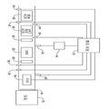
도 1은 본 개시의 원리에 따른 검댕 축적 확인 시스템을 구비한 배기가스 후처리 시스템 및 엔진의 개략도이다.
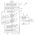
도 2는 후처리 시스템의 미립자 필터의 검댕 축적을 확인하는 방법을 도시한 흐름도이다.
도면들 중 일부 도면들에 걸쳐서 상응하는 참조 번호들은 상응하는 부분들을 나타낸다.The drawings described herein are for illustrative purposes only, and are not intended to limit the scope of the present disclosure, but rather to illustrate all possible implementations.
1 is a schematic diagram of an exhaust aftertreatment system and engine with a soot accumulation confirmation system in accordance with the principles of the present disclosure;
Fig. 2 is a flow chart showing a method for confirming soot accumulation of a particulate filter in a post-treatment system.
Corresponding reference numerals throughout the several figures of the drawings represent corresponding parts.
이제 첨부 도면을 참조하여 예시적인 실시예들을 더욱 충분히 설명하기로 한다.Exemplary embodiments will now be described more fully with reference to the accompanying drawings.
본 개시가 완전해지고 당업자에게 그 범주를 충분히 전달하도록 예시적인 실시예들이 제공된다. 본 개시의 실시예가 완전히 이해할 수 있도록 특정 구성요소, 장치 및 방법의 예와 같은 다수의 구체적인 상세가 제시된다. 구체적인 상세가 이용되지 않아도 되고, 예시적인 실시예들이 다수의 여러 가지 양태로 구현될 수 있으며, 어떤 것도 본 개시의 범주를 한정하는 것으로 해석되지 않아야 한다는 것이 당업자에게 명백할 것이다. 일부 예시적인 실시예에서, 주지의 공정, 주지의 장치 구조 및 주지의 기술은 상세하게 설명되지 않는다.Exemplary embodiments are provided so that this disclosure will be thorough and fully convey the scope of the invention to those skilled in the art. Numerous specific details are set forth such as examples of specific elements, devices, and methods in order that the embodiments of the disclosure may be fully understood. It will be apparent to those skilled in the art that the specific details may not be utilized and that the exemplary embodiments may be implemented in numerous different manners and that nothing should be construed as limiting the scope of the present disclosure. In some exemplary embodiments, well-known processes, well-known device structures, and well-known techniques are not described in detail.
본원에서 사용된 용어는 오직 예시적인 특정 실시예를 설명하는 목적을 위한 것이며, 한정하고자 하는 것이 아니다. 본원에서 사용되는 바와 같이, 문맥에서 명확히 다르게 표시하지 않는다면, 단수형("a", "an" 및 "the")은 복수형 또한 포함하는 것으로 의도될 수 있다. "포함한다(comprises)", "포함하는(comprising, including)" 및 "갖는(having)"이라는 용어는 포괄적인 의미이므로, 언급된 특징, 정수, 단계, 작동, 요소 및/또는 구성요소의 존재를 명시하지만, 하나 이상의 다른 특징, 정수, 단계, 작동, 요소, 구성요소 및/또는 이들의 그룹의 존재 및 추가를 배제하지 않는다. 본원에 설명된 방법 단계, 과정 및 작동은, 수행 순서로서 분명히 나타나 있지 않은 경우, 반드시 논의되거나 예시된 특정 순서로 수행할 필요가 있는 것으로 해석되지 않는다. 또한, 추가적이거나 대안적인 단계가 이용될 수 있음을 이해할 것이다.The terminology used herein is for the purpose of describing particular exemplary embodiments only, and is not intended to be limiting. As used herein, " a ", "an ", and" the ", may be intended to also include the plural, unless the context clearly dictates otherwise. The terms " comprises, " " including, "and" having "are intended to be inclusive, and the presence of stated features, integers, steps, operations, elements and / But do not preclude the presence or addition of one or more other features, integers, steps, operations, elements, components, and / or groups thereof. The method steps, processes, and operations described herein are not necessarily to be interpreted as needing to be performed in the specific order discussed or illustrated, unless clearly indicated as a sequence of acts. It will also be appreciated that additional or alternative steps may be used.
어떤 요소 또는 층이 다른 요소 또는 층 "위에(on)" 있거나, 이에 "맞물려(engaged to)" 있거나, "연결되어(connected to)" 있거나, "결합되어(coupled to)" 있다고 지칭되는 경우, 이는 다른 요소 또는 층의 바로 위에 있거나, 직접적으로 맞물리거나, 연결되거나, 결합되어 있을 수 있고, 또는 그 사이에 개재된 요소 또는 층이 존재할 수 있다. 반대로, 어떤 요소가 다른 요소 또는 층의 "바로 위에" 있거나, "직접적으로 맞물려" 있거나, "직접적으로 연결되어" 있거나, "직접 결합되어" 있는 것으로 지칭될 때, 그 사이에 개재된 요소 또는 층이 존재하지 않을 수 있다. 요소들 간의 관계를 기술하는 데 사용되는 다른 단어들은 마찬가지의 방식으로(예를 들면, "사이에"와 "사이에 직접적으로", "인접하여"와 "직접적으로 인접하여" 등) 해석되어야 한다. 본원에 사용되는 바와 같이, "및/또는"이라는 용어는 연관된 열거 항목들 중 하나 이상의 모든 조합을 포함한다.When an element or layer is referred to as being "on", "engaged to", "connected to", or "coupled to" another element or layer, It may be directly on top of another element or layer, be directly engaged, connected, coupled, or there may be an intervening element or layer therebetween. Conversely, when an element is referred to as being "directly on", "directly in", "directly connected", or "directly coupled" to another element or layer, May not exist. Other words used to describe the relationship between elements should be interpreted in a similar manner (e.g., between "between" and "directly", "adjacent", and "directly adjacent") . As used herein, the term "and / or" includes all combinations of one or more of the associated enumerated items.
본원에서 다양한 요소, 구성요소, 영역, 층 및/또는 부분을 기술하기 위해, 제1, 제2, 제3 등의 용어가 사용될 수 있지만, 이들 요소, 구성요소, 영역, 층 및/또는 부분이 이들 용어에 의해 한정되지 않아야 한다. 이 용어들은 하나의 요소, 구성요소, 영역, 층 또는 부분을 다른 영역, 층 또는 부분과 구별하기 위해서만 사용될 수 있다. 문맥에 의해 명확하게 나타나지 않는다면, "제1", "제2"와 같은 용어 및 숫자를 나타내는 다른 용어는 본원에서 사용될 때 차례 또는 순서를 의미하지 않는다. 따라서, 하기에 논의되는 제1 요소, 구성요소, 영역, 층 또는 부분은, 예시적인 실시예의 교시를 벗어나지 않으면서 제2 요소, 구성요소, 영역, 층 또는 부분으로 칭할 수 있다.Although the terms first, second, third, etc. may be used herein to describe various elements, components, regions, layers, and / or portions, And should not be limited by these terms. These terms may only be used to distinguish one element, element, region, layer or section from another region, layer or section. Unless specifically stated by context, terms such as " first, "" second, " and other terms that refer to numbers do not mean a turn or order when used herein. Thus, a first element, component, region, layer or section discussed below may be referred to as a second element, component, region, layer or section without departing from the teachings of the exemplary embodiments.
"내측", "외측", "아래", "하부", "하측", "상부", "상측" 등과 같이 공간적으로 상대적인 용어들이, 도면에 예시된 바와 같이, 하나의 요소 또는 특징부와 다른 요소 또는 특징부의 관계를 기술하기 위한 설명을 용이하게 하기 위해 본원에서 사용될 수 있다. 공간적으로 상대적인 용어들은 도면에 도시된 배향 외에도 사용 또는 작동 시의 장치의 상이한 배향들을 포함하는 것으로 의도될 수 있다. 예를 들면, 도면에서 장치가 뒤집어진다면, 다른 요소 또는 특징부의 "아래" 또는 "하부"에 있는 것으로 기술된 요소가 다른 요소 또는 특징부의 "상부"에 배향될 것이다. 따라서, "하부"라는 예시적인 용어는 상부 및 하부의 배향을 둘 다 포함할 수 있다. 장치는 다르게 배향되어(90도 또는 다른 배향으로 회전됨), 본원에 사용된 공간적으로 상대적인 설명 어구가 이에 따라 해석될 수 있다.Spatially relative terms such as "inner "," outer ", "lower "," lower ", & May be used herein to facilitate describing the relationship of elements or features. Spatially relative terms may be intended to encompass different orientations of the device in use or operation in addition to the orientation shown in the figures. For example, if the device is inverted in the figures, elements described as being "under" or "under" another element or feature will be oriented "above" another element or feature. Thus, an exemplary term "lower" may include both upper and lower orientations. The device may be oriented differently (rotated in 90 degrees or other orientations) and the spatially relative description phrase used herein may be interpreted accordingly.
도 1은 예시적인 엔진(12)으로부터 배기가스 통로(14)로의 배기가스 출력을 처리하기 위한 배기가스 후처리 시스템(10)을 도시한다. 터보차저(16)는 배기가스 스트림에 위치된 피동 부재(미도시)를 포함한다. 엔진 작동 중, 배기가스 스트림은 피동 부재를 회전시켜 엔진(12)의 흡기 통로(미도시)로 압축 공기를 제공하게 한다. 배기가스 후처리 시스템(10)은 자연 흡기 엔진 또는 터보차저를 포함하지 않는 임의의 다른 엔진으로부터의 배기가스 출력을 처리하는 데에도 사용될 수 있음을 이해할 것이다.1 shows an exhaust aftertreatment system 10 for processing the exhaust gas output from an exemplary engine 12 to an exhaust gas passage 14. The exhaust aftertreatment system 10 is shown in FIG. The turbocharger 16 includes a driven member (not shown) located in the exhaust gas stream. During engine operation, the exhaust stream causes the driven member to rotate to provide compressed air to the intake passage (not shown) of the engine 12. It will be appreciated that the exhaust aftertreatment system 10 may also be used to process the exhaust gas output from any other engine that does not include a natural intake engine or turbocharger.
배기가스 후처리 시스템(10)은 버너(18), 탄화수소 인젝터(20), 디젤 산화 촉매(DOC)(22), 디젤 배기 유체(DEF) 주입 시스템(24), 하나 이상의 혼합기(26), SCR 촉매(28), 디젤 미립자 필터(DPF)(30), 및 제어 모듈(32)을 포함할 수 있다. DPF(30)는 SCR 코팅 디젤 미립자 필터일 수 있으며, 배기가스 스트림으로부터 검댕(즉, 디젤 미립자)을 여과하여 주위 환경으로의 입자상 물질(PM) 배출을 감소시킨다. 시간의 경과에 따라, 검댕이 DPF(30)에 축적될 수 있고, 이는 엔진(12), DPF(30) 및/또는 배기가스 후처리 시스템(10)의 다른 구성요소들의 성능을 저해할 수 있다.The exhaust aftertreatment system 10 includes a burner 18, a
탄화수소 인젝터(20)는 DOC(22) 상에 탄화수소를 분무할 수 있으며, 이는 전술된 바와 같이 DPF(30)를 재생(즉, 이로부터 검댕을 제거)하기 위해 열을 생성할 수 있다. 버너(18)는 터보차저(16)의 하류이자 DOC(22)의 상류에 위치될 수 있고, DOC(22)에서의 열-생성 반응을 촉진하기 위해 미리 결정된 온도로 배기가스 통로(14) 내의 배기가스를 가열하도록 선택적으로 작동될 수 있다.The
DEF 주입 시스템(24)은 인젝터(33) 및 환원제 탱크(34)를 포함할 수 있다. 인젝터(33)는 환원제 탱크(34)로부터 SCR 촉매(28) 상류의 배기가스 스트림 내로 환원제(예컨대, 요소)를 주입할 수 있다. 혼합기(26)는, 주입된 환원제가 SCR 촉매(28)에 도달하기 전에, 환원제를 배기가스와 혼합할 수 있다. SCR 촉매(28)는 배기가스 중의 질소 산화물(NOx)을 이원자 질소(N2), 물 및/또는 이산화탄소(CO2)로 전환시킬 수 있다.The DEF injection system 24 may include an
제어 모듈(32)은 하나 이상의 소프트웨어 또는 펌웨어 프로그램을 실행하는 주문형 반도체(ASIC), 전자 회로, 프로세서(공유, 전용 또는 그룹) 및/또는 메모리(공유, 전용 또는 그룹), 및/또는 조합 논리 회로, 및/또는, 예를 들어, 기술된 기능을 제공하는 다른 적합한 구성요소들을 포함하거나 또는 이의 일부일 수 있다. 제어 모듈(32)은 하나 이상의 다른 차량 시스템을 제어하는 제어부를 포함하거나 또는 이의 일부일 수 있다. 대안적으로, 제어 모듈(32)은 배기가스 후처리 시스템(10) 전용의 제어부일 수 있다.
제어 모듈(32)은 버너(18), 탄화수소 인젝터(20)(및/또는 탄화수소 인젝터(20)를 통해 탄화수소를 강제 주입하는 제1 펌프), 및/또는 DEF 주입 시스템(24)(예컨대, 인젝터(33)를 통해 환원제를 강제 주입하는 제2 펌프)의 제어 동작과 통신할 수 있다. 제어 모듈(32)은 또한 제1 및 제2 온도 센서(36, 37), 배기가스 압력 센서(40), 제1 및 제2 NOx 센서(42, 43), 및 암모니아 센서(44)와 통신할 수 있다. 제1 온도 센서는 DOC(22)에서의 또는 그 근처의 온도를 측정할 수 있다. 제2 온도 센서(37)는 SCR 촉매(28)에서의 또는 그 근처의 온도를 측정할 수 있다. 배기가스 질량 유량 센서(미도시)는 SCR 촉매(28)와 DPF(30) 사이의 배기가스 통로(14)를 통해 흐르는 배기가스 스트림의 질량 유량을 측정할 수 있다. 대안적으로, 이러한 질량 유량 값은 엔진 속도 및/또는 다른 엔진 작동 파라미터에 기반하여 계산되거나 또는 엔진 제어 시스템으로부터 확인될 수 있다. 배기가스 압력 센서(40)는 DOC(22)와 DPF(30) 사이의 배기가스 스트림의 압력을 측정할 수 있다. 제1 NOx 센서(42)는 DOC(22)의 입구에서의 또는 그 근처의 배기가스 스트림 내의 NOx의 양을 측정할 수 있다. 제2 NOx 센서(43)는 SCR 촉매(28)의 출구에서의 또는 그 근처의 배기가스 스트림 내의 NOx의 양을 측정할 수 있다. 암모니아 센서(44)는 DPF(30)의 출구에서의 또는 DPF(30)의 하류의 배기가스 스트림 내 암모니아의 양을 측정할 수 있다. 제어 모듈(32)은 제1 및 제2 온도 센서(36, 37), 배기가스 압력 센서(40), 제1 및 제2 NOx 센서(42, 43), 및/또는 암모니아 센서(44)로부터 수신된 배기가스 질량 유량 및 데이터에 기반하여 DEF 주입 시스템(24)의 작동을 제어하고 DPF(30)의 검댕 축적을 확인할 수 있다.The
이제 도 1 및 도 2를 참조하면, DEF 주입 시스템(24)의 작동을 제어하고 DPF(30)의 검댕 축적을 확인하는 방법(100)이 제공된다. 단계 110에서, 제어 모듈(32)은 SCR 촉매(28)의 온도, SCR 촉매(28)와 DPF(30) 사이의 배기가스 통로(14)를 통해 흐르는 배기가스 스트림의 질량 유량, SCR 촉매(28)와 DPF(30) 사이의 배기가스 스트림의 압력, 및 DPF(30)의 입구에서의 또는 그 상류의 배기가스 스트림 내 NOx의 양을 확인할 수 있다. 이들 파라미터는 예를 들어 센서(37, 40, 42)에 의해 측정되고/되거나 엔진(12) 및/또는 후처리 시스템(10)의 하나 이상의 작동 파라미터에 기반하여 계산될 수 있다Referring now to Figures 1 and 2, a
단계 120에서, 제어 모듈(32)은 미리 결정된 알파 비(즉, 배기가스 스트림 내 암모니아와 NOx의 미리 결정된 비율)를 달성하게 되는 DEF 주입 시스템(24)의 초기 주입 속도를 계산할 수 있다. 일부 실시예에서, 미리 결정된 알파 비는 예를 들어 1일 수 있다. 주입 속도는, 단계 110에서 센서(40, 42)로부터 수신된 배기가스 질량 유량 속도 및 데이터에 기반하여 결정될 수 있다. 주입 속도는 미리 결정된 알파 비에 더하여 또는 그 대신에 하나 이상의 파라미터에 기반하여 결정될 수 있음을 이해할 것이다. 초기 주입 속도를 결정한 후, 제어 모듈(32)은 DEF 주입 시스템(24)으로 하여금 초기 주입 속도로 환원제를 배기가스 스트림 내에 주입하게 할 수 있다.In
단계 130에서, 제어 모듈(32)은 암모니아 슬립 값(즉, DPF(30) 하류의 미반응 암모니아의 양)을 확인할 수 있다. 암모니아 슬립 값은 암모니아 센서(44)로부터 수신된 측정 값일 수 있다. 그 후, 단계 140에서, 제어 모듈(32)은 측정된 암모니아 슬립 값이 미리 결정되거나 예상된 암모니아 슬립 값보다 큰지 여부를 확인할 수 있다. 측정된 암모니아 슬립 값이 미리 결정된 값보다 큰 경우, 제어 모듈(32)은, 단계 150에서, DEF 주입 시스템(24)의 주입 속도를 감소시킬 수 있다. 주입 속도를 감소시킨 후, 제어 모듈(32)은 단계 130에서 암모니아 센서(44)로부터 갱신된 암모니아 슬립 측정값을 획득할 수 있다. 그 후, 단계 140에서, 제어 모듈(32)은 갱신된 암모니아 슬립 값이 미리 결정된 값보다 큰지 여부를 확인할 수 있다. 갱신된 암모니아 슬립 값이 미리 결정된 값보다 크지 않다고 제어 모듈(32)이 확인한 경우, 제어 모듈(32)은, 단계 160에서, 갱신된 암모니아 슬립 값이 미리 결정된 값보다 작은지를 확인할 수 있다. 갱신된 암모니아 슬립 값이 미리 결정된 값보다 작은 경우, 제어 모듈(32)은 단계 170에서 DEF 주입 시스템(24)의 주입 속도를 증가시키고, 그 후 필요에 따라 단계 130, 140, 150, 160 및 170을 반복할 수 있다. 제어 모듈(32)이 단계 140 전에 단계 160을 수행하거나 또는 제어 모듈(32)이 단계 140 및 160을 실질적으로 동시에 수행할 수 있으며, 암모니아 센서(44)에 의해 측정된 암모니아 슬립 값이 미리 결정된 값과 동일하거나 대략 동일할 때까지 주입 속도를 조정할 수 있음을 이해할 것이다.At
일단 주입 속도가 원하는 암모니아 슬립을 달성하도록 설정되면, 제어 모듈(32)은 단계 180에서 이러한 주입 속도에 기반하여 알파 비를 계산할 수 있다. 단계 190에서, 제어 모듈(32)은 단계 180에서 계산된 알파 비(즉, 암모니아 센서(44)에서 원하는 암모니아 슬립 값을 산출하는 주입 속도에 상응하는 알파 비)에 기반하여 DPF(30)의 검댕 축적을 확인할 수 있다. 검댕 축적은 단계 180에서 계산된 알파 비에 반비례할 수 있다. 제어 모듈(32)은 제어 모듈(32)의 메모리에 저장된 룩업 테이블로부터 검댕 축적을 확인할 수 있다. 룩업 테이블에 저장된 값은 실험을 통해 결정될 수 있다. 주어진 DPF에 대한 검댕 축적 값이 단계 180에서 계산된 알파 비와 미리 결정된 알파 비의 차이와 관련하여 변한다는 것을 알 수 있다.Once the infusion rate is set to achieve the desired ammonia slip, the
일부 실시예에서, 단계 190에서 확인된 검댕 축적 값에 가중 인자가 부여될 수 있고, 계산된 검댕 축적 값은 시간 경과에 따라 통합되어 신호 잡음 및 필터 노화의 원인이 될 수 있다. 예를 들어 가중 인자는 마지막 DPF 재생 이벤트 이후의 시간 및 SCR 촉매(28) 또는 DPF(30)의 사용 연수에 해당될 수 있다.In some embodiments, weighting factors may be assigned to the soot accumulation values identified in
DPF(30)의 검댕 축적을 확인한 후, 제어 모듈(32)은, 단계 200에서, 검댕 축적이 미리 결정된 임계값보다 큰지 확인할 수 있다. DPF(30) 상의 검댕 축적이 미리 결정된 임계값보다 크다고 제어 모듈(32)이 확인하는 경우, 제어 모듈(32)은, 단계 210에서, 재생 이벤트를 촉발할 수 있다. 미리 결정된 임계값은 DPF(30), 엔진(12) 및/또는 배기가스 후처리 시스템(10)의 임의의 다른 하나 이상의 구성요소의 원하는 수준의 성능을 달성하도록 선택될 수 있다. 재생 이벤트 동안, 제어 모듈(32)은 전술된 바와 같이 탄화수소 인젝터(20)로 하여금 DOC(22) 상류의 배기가스 스트림 내로 탄화수소를 분무하게 할 수 있고, 그리고/또는 제어 모듈(32)은 버너(18)가 점화되어 DPF(30)의 재생을 촉진하도록 할 수 있다. 방법(100)의 일부 또는 전부가 연속적으로 또는 단속적으로 반복될 수 있음을 이해할 것이다.After confirming the soot accumulation of the
실시예의 상기 설명이 예시 및 설명의 목적으로 제공되었다. 이는 포괄적이거나 본 개시를 한정하기 위한 것은 아니다. 특정 실시예의 개별 요소 또는 특징부는 전반적으로 그러한 특정 실시예에 한정되지 않지만, 구체적으로 도시되거나 설명되지 않더라도, 적용 가능한 경우, 상호 교환 가능하며, 선택된 실시예에서 사용될 수 있다. 이는 또한 다수의 방식으로 변경될 수 있다. 이러한 변경은 본 개시로부터 벗어난 것으로 간주되지 않으며, 이러한 모든 변형은 본 개시의 범주 내에 포함되는 것으로 의도된다.The foregoing description of the embodiments has been presented for purposes of illustration and description. It is not intended to be exhaustive or to limit the present disclosure. The individual elements or features of a particular embodiment are not limited to such specific embodiments in general, but, if not specifically shown or described, they are interchangeable, if applicable, and may be used in selected embodiments. It can also be modified in a number of ways. Such variations are not to be regarded as a departure from the present disclosure, and all such variations are intended to be included within the scope of this disclosure.
Claims (22)
상기 연소 엔진으로부터 배출된 배기가스를 여과하도록 구성된 미립자 필터;
상기 미립자 필터 상류의 배기가스 스트림 내로 환원제를 주입하도록 구성된 환원제 주입 시스템;
상기 미립자 필터 하류의 배기가스 스트림의 암모니아 농도를 감지하도록 구성된 암모니아 센서; 및
상기 암모니아 센서와 통신하며, 상기 암모니아 센서로부터 수신된 데이터에 기반하여 상기 미립자 필터의 검댕 축적을 확인하는 제어 모듈을 포함하는, 후처리 시스템.A post-treatment system for treating exhaust gas discharged from a combustion engine,
A particulate filter configured to filter the exhaust gas discharged from the combustion engine;
A reducing agent injection system configured to inject a reducing agent into the exhaust gas stream upstream of the particulate filter;
An ammonia sensor configured to detect an ammonia concentration of the exhaust gas stream downstream of the particulate filter; And
And a control module communicating with the ammonia sensor and verifying the soot accumulation of the particulate filter based on data received from the ammonia sensor.
상기 제어 모듈과 통신하며 배기가스 스트림 내의 NOx 농도를 감지하도록 구성된 NOx 센서를 더 포함하며,
상기 제어 모듈은 상기 NOx 센서로부터 수신된 데이터에 기반하여 상기 미립자 필터의 검댕 축적을 확인하는, 후처리 시스템.The method according to claim 1,
Further comprising a NO x sensor in communication with the control module and configured to sense NO x concentration in the exhaust stream,
Wherein the control module confirms the soot accumulation of the particulate filter based on the data received from the NO x sensor.
상기 NOx 센서는 상기 미립자 필터의 상류에서 NOx의 농도를 확인하도록 위치되는, 후처리 시스템.3. The method of claim 2,
Wherein the NO x sensor is positioned to identify the concentration of NO x upstream of the particulate filter.
상기 제어 모듈은 암모니아와 NOx의 비율에 기반하여 상기 미립자 필터의 검댕 축적을 확인하는, 후처리 시스템.3. The method of claim 2,
Wherein the control module identifies the soot accumulation of the particulate filter based on a ratio of ammonia to NO x .
상기 제어 모듈은, 상기 미립자 필터 하류의 배기가스 스트림 내 암모니아의 양에 기반하여 상기 미립자 필터의 검댕 축적을 확인하는, 후처리 시스템.The method according to claim 1,
Wherein the control module identifies the soot accumulation of the particulate filter based on the amount of ammonia in the exhaust stream downstream of the particulate filter.
상기 미립자 필터의 상류에 배치되어 상기 제어 모듈과 통신하는 재생 장치를 더 포함하며,
상기 제어 모듈은, 상기 미립자 필터의 검댕 축적이 미리 결정된 임계값을 초과한다고 상기 제어 모듈이 확인한 것에 응답하여 상기 재생 장치를 구동시키는, 후처리 시스템.The method according to claim 1,
Further comprising a playback device disposed upstream of the particulate filter and in communication with the control module,
Wherein the control module drives the playback device in response to the check confirmed by the control module that the soot accumulation of the particulate filter exceeds a predetermined threshold value.
상기 재생 장치는 탄화수소 인젝터 또는 버너, 또는 상기 탄화수소 인젝터와 상기 버너를 포함하는, 후처리 시스템.The method according to claim 6,
Wherein the regenerator comprises a hydrocarbon injector or burner, or the hydrocarbon injector and the burner.
상기 제어 모듈은 상기 환원제 주입 시스템과 통신하며, 원하는 암모니아 농도를 달성하기 위해 배기가스 스트림 내로 주입되는 환원제의 양을 조절하는, 후처리 시스템.The method according to claim 1,
Wherein the control module is in communication with the reducing agent injection system and regulates the amount of reducing agent injected into the exhaust gas stream to achieve a desired ammonia concentration.
상기 제어 모듈은 원하는 암모니아 농도 및 상기 미립자 필터의 상류에서 감지된 NOx의 농도에 근거하여 암모니아와 NOx의 비율을 확인하며, 상기 제어 모듈은 상기 비율에 근거하여 상기 미립자 필터의 검댕 축적을 확인하는, 후처리 시스템.9. The method of claim 8,
The control module checks the ratio of ammonia to NO x based on the desired ammonia concentration and the concentration of NO x detected upstream of the particulate filter, and the control module checks the soot accumulation of the particulate filter based on the ratio Post processing system.
상기 제어 모듈은 예상되는 알루미늄 슬립 값에 대한 실제 암모니아 슬립 값에 기반하여 상기 미립자 필터의 검댕 축적을 확인하는, 후처리 시스템.The method according to claim 1,
Wherein the control module identifies the soot accumulation of the particulate filter based on an actual ammonia slip value for an anticipated aluminum slip value.
상기 미립자 필터 하류의 배기가스 중의 암모니아 농도를 감지하도록 구성된 암모니아 센서; 및
상기 암모니아 센서와 통신하며, 상기 암모니아 센서로부터 수신된 데이터를 기반으로 상기 미립자 필터의 검댕 축적을 확인하는 제어 모듈을 포함하는, 검댕 축적 확인 시스템.A soot accumulation confirmation system for a particulate filter of a post-treatment system of a combustion engine,
An ammonia sensor configured to detect an ammonia concentration in the exhaust gas downstream of the particulate filter; And
And a control module communicating with the ammonia sensor and verifying the soot accumulation of the particulate filter based on the data received from the ammonia sensor.
상기 제어 모듈과 통신하며 배기가스 중의 NOx 농도를 감지하도록 구성된 NOx 센서를 더 포함하며,
상기 제어 모듈은 상기 NOx 센서로부터 수신된 데이터를 기반으로 상기 미립자 필터의 검댕 축적을 확인하는, 검댕 축적 확인 시스템.12. The method of claim 11,
Further comprising a NO x sensor in communication with the control module and configured to sense the NO x concentration in the exhaust gas,
Wherein the control module confirms soot accumulation of the particulate filter based on data received from the NO x sensor.
상기 NOx 센서는 상기 미립자 필터의 상류에서 NOx의 농도를 확인하도록 위치된, 검댕 축적 확인 시스템.13. The method of claim 12,
Wherein the NO x sensor is positioned to ascertain the concentration of NO x upstream of the particulate filter.
상기 제어 모듈은 암모니아와 NOx의 비율에 기반하여 상기 미립자 필터의 검댕 축적을 확인하는, 검댕 축적 확인 시스템.13. The method of claim 12,
Wherein the control module confirms the soot accumulation of the particulate filter based on the ratio of ammonia to NO x .
상기 제어 모듈은, 상기 미립자 필터 하류의 배기가스 스트림 내 암모니아의 양에 기반하여 상기 미립자 필터의 검댕 축적을 확인하는, 검댕 축적 확인 시스템.12. The method of claim 11,
Wherein the control module identifies the soot accumulation of the particulate filter based on the amount of ammonia in the exhaust stream downstream of the particulate filter.
상기 미립자 필터의 상류에 배치되어 상기 제어 모듈과 통신하는 재생 장치를 더 포함하며,
상기 제어 모듈은, 상기 미립자 필터의 검댕 축적이 미리 결정된 임계값을 초과한다고 상기 제어 모듈이 확인한 것에 응답하여 상기 재생 장치를 구동시키는, 검댕 축적 확인 시스템.12. The method of claim 11,
Further comprising a playback device disposed upstream of the particulate filter and in communication with the control module,
And the control module drives the playback device in response to the control module's confirmation that the soot accumulation of the particulate filter exceeds a predetermined threshold value.
상기 재생 장치는 탄화수소 인젝터 또는 버너, 또는 상기 탄화수소 인젝터와 상기 버너를 포함하는, 검댕 축적 확인 시스템.17. The method of claim 16,
Wherein the recycling apparatus comprises a hydrocarbon injector or burner, or the hydrocarbon injector and the burner.
상기 제어 모듈은 환원제 주입 시스템과 통신하며, 원하는 암모니아 농도를 달성하기 위해 배기가스 내로 주입되는 환원제의 양을 조절하는, 검댕 축적 확인 시스템.12. The method of claim 11,
Wherein the control module communicates with the reducing agent injection system and regulates the amount of reducing agent injected into the exhaust gas to achieve a desired ammonia concentration.
상기 제어 모듈은 원하는 암모니아 농도 및 상기 미립자 필터의 상류에서 감지된 NOx의 농도에 기반하여 암모니아와 NOx의 비율을 확인하며, 상기 제어 모듈은 상기 비율에 기반하여 상기 미립자 필터의 검댕 축적을 확인하는, 검댕 축적 확인 시스템.19. The method of claim 18,
The control module checks the ratio of ammonia to NO x based on the desired ammonia concentration and the NO x concentration sensed upstream of the particulate filter, and the control module checks the soot accumulation of the particulate filter based on the ratio , Soot accumulation confirmation system.
상기 제어 모듈은 예상되는 알루미늄 슬립 값에 대한 실제 암모니아 슬립 값에 근거하여 상기 미립자 필터의 검댕 축적을 확인하는, 검댕 축적 확인 시스템.12. The method of claim 11,
Wherein the control module confirms the soot accumulation of the particulate filter based on the actual ammonia slip value for the anticipated aluminum slip value.
상기 디젤 미립자 필터 하류의 배기가스 스트림 내의 암모니아 양을 나타내는 암모니아 센서로부터 데이터를 수신하는 단계;
상기 디젤 미립자 필터 하류의 배기가스 스트림 내의 NOx 양을 확인하는 단계;
상기 NOx 센서 및 상기 암모니아 센서로부터 수신된 데이터에 기반하여 암모니아와 NOx의 비율을 확인하는 단계; 및
상기 비율에 근거하여 상기 디젤 미립자 필터의 검댕 축적을 확인하는 단계를 포함하는 방법.A method for confirming soot accumulation of a diesel particulate filter of a post-treatment system for a combustion engine,
Receiving data from an ammonia sensor indicative of the amount of ammonia in the exhaust stream downstream of the diesel particulate filter;
Identifying the amount of NO x in the exhaust stream downstream of the diesel particulate filter;
Determining a ratio of ammonia to NO x based on data received from the NO x sensor and the ammonia sensor; And
And confirming soot accumulation of the diesel particulate filter based on the ratio.
상기 검댕 축적에 기반하여 상기 디젤 미립자 필터 상류의 배기가스 스트림 내에 배치된 재생 장치를 제어하는 단계를 더 포함하는 방법.22. The method of claim 21,
And controlling the regenerator disposed in the exhaust gas stream upstream of the diesel particulate filter based on the soot accumulation.
Applications Claiming Priority (3)
| Application Number | Priority Date | Filing Date | Title |
|---|---|---|---|
| US14/032,665 | 2013-09-20 | ||
| US14/032,665 US9371767B2 (en) | 2013-09-20 | 2013-09-20 | Soot load determination system |
| PCT/US2014/056208 WO2015042217A1 (en) | 2013-09-20 | 2014-09-18 | Soot load determination system |
Publications (1)
| Publication Number | Publication Date |
|---|---|
| KR20160055256A true KR20160055256A (en) | 2016-05-17 |
Family
ID=52689368
Family Applications (1)
| Application Number | Title | Priority Date | Filing Date |
|---|---|---|---|
| KR1020167009626A KR20160055256A (en) | 2013-09-20 | 2014-09-18 | Soot load determination system |
Country Status (6)
| Country | Link |
|---|---|
| US (1) | US9371767B2 (en) |
| JP (1) | JP2016530423A (en) |
| KR (1) | KR20160055256A (en) |
| CN (1) | CN105556076B (en) |
| DE (1) | DE112014004319T5 (en) |
| WO (1) | WO2015042217A1 (en) |
Cited By (1)
| Publication number | Priority date | Publication date | Assignee | Title |
|---|---|---|---|---|
| KR102054214B1 (en) * | 2018-10-26 | 2019-12-10 | (주)세라컴 | System for after-treatment of exhaust gas, and method for controlling of the same |
Families Citing this family (22)
| Publication number | Priority date | Publication date | Assignee | Title |
|---|---|---|---|---|
| ES2892151T3 (en) * | 2011-11-22 | 2022-02-02 | Deutz Ag | Device and procedure for the purification of exhaust gases from diesel engines |
| US9334773B2 (en) * | 2013-10-31 | 2016-05-10 | Cummins Ip, Inc. | Particulate matter sensor regeneration |
| WO2015188189A1 (en) * | 2014-06-06 | 2015-12-10 | Filter Sensing Technologies, Inc. | Radio frequency state variable measurement system and method |
| WO2017023766A1 (en) | 2015-08-03 | 2017-02-09 | Cummins Emission Solutions Inc. | Sensor configuration for aftertreatment system including scr on filter |
| US9879580B2 (en) * | 2015-08-19 | 2018-01-30 | Cummins, Inc. | Diagnostic methods for a high efficiency exhaust aftertreatment system |
| EP3184769B1 (en) * | 2015-12-25 | 2018-07-18 | Kubota Corporation | Exhaust apparatus for diesel engine |
| JP6586377B2 (en) * | 2016-02-23 | 2019-10-02 | 日野自動車株式会社 | Exhaust purification device |
| WO2018057170A1 (en) * | 2016-09-20 | 2018-03-29 | Caterpillar Inc. | After-treatment system |
| CN107024444A (en) * | 2017-02-15 | 2017-08-08 | 武汉启呈环保技术有限公司 | A kind of diesel engine denitration the escaping of ammonia tests reponse system |
| CN106896078B (en) * | 2017-02-15 | 2019-06-04 | 武汉启呈环保技术有限公司 | A kind of diesel engine vent gas denitration the escaping of ammonia test device |
| CN108131188B (en) * | 2018-01-29 | 2020-10-27 | 中国第一汽车股份有限公司 | Particulate filter control system |
| DE112018007113T5 (en) * | 2018-02-19 | 2020-11-05 | Cummins Emission Solutions Inc. | Improved diesel particulate filter linearity with thin ash layer |
| CN108645964B (en) * | 2018-04-23 | 2020-11-06 | 华北电力科学研究院有限责任公司 | Method and system for measuring ammonia escape mean value of SCR (Selective catalytic reduction) denitration device based on urea reducing agent |
| US20190353071A1 (en) * | 2018-05-18 | 2019-11-21 | GM Global Technology Operations LLC | Selective catalytic reduction device control |
| US11008917B2 (en) * | 2018-08-24 | 2021-05-18 | International Engine Intellectual Property Company, Llc. | DEF dosing using multiple dosing locations while maintaining high passive soot oxidation |
| JP7003878B2 (en) * | 2018-08-30 | 2022-01-21 | トヨタ自動車株式会社 | Exhaust purification device for internal combustion engine |
| DE102018220715A1 (en) * | 2018-11-30 | 2020-06-04 | Volkswagen Aktiengesellschaft | Exhaust gas aftertreatment system and method for exhaust gas aftertreatment of an internal combustion engine |
| US11286838B2 (en) * | 2019-06-26 | 2022-03-29 | Ford Global Technologies, Llc | Methods for vehicle emissions control |
| DE102020123028A1 (en) * | 2019-09-13 | 2021-03-18 | Ngk Spark Plug Co., Ltd. | Gas sensor control device, gas sensor device and control device for an internal combustion engine |
| DE102020202551A1 (en) * | 2020-02-28 | 2021-09-02 | Vitesco Technologies GmbH | Method and device for diagnosing a coated particle filter arranged in an exhaust gas duct of a motor vehicle |
| US11339702B2 (en) * | 2020-09-15 | 2022-05-24 | Ford Global Technologies, Llc | Methods and systems for an exhaust gas aftertreatment system |
| CN114964793A (en) * | 2022-04-24 | 2022-08-30 | 潍柴动力股份有限公司 | SDPF ash loading amount detection method and device, SDPF ash loading amount monitoring method and device, and vehicle |
Family Cites Families (15)
| Publication number | Priority date | Publication date | Assignee | Title |
|---|---|---|---|---|
| US6978604B2 (en) | 2003-11-06 | 2005-12-27 | International Engine Intellectual Property Company, Llc | Soot burn-off control strategy for a catalyzed diesel particulate filter |
| WO2008103113A1 (en) | 2007-02-21 | 2008-08-28 | Volvo Lastvagnar Ab | On-board-diagnosis method for an exhaust aftertreatment system and on-board-diagnosis system for an exhaust aftertreatment system |
| US8316635B2 (en) | 2008-06-13 | 2012-11-27 | Cummins Filtration Ip, Inc. | Methods of increasing accuracy of soot load estimates |
| AU2008361679B2 (en) | 2008-09-10 | 2014-06-05 | Mack Trucks, Inc. | Method for estimating soot loading in a diesel particulate filter, and engine and aftertreatment system |
| EP2406473B1 (en) * | 2009-03-12 | 2018-02-28 | Volvo Lastvagnar AB | Operating method for an exhaust aftertreatment system and exhaust aftertreatment system |
| US8316634B2 (en) | 2009-03-24 | 2012-11-27 | GM Global Technology Operations LLC | Ammonia load control for SCR catalyst prior to DPF regeneration |
| US8516804B2 (en) | 2010-02-26 | 2013-08-27 | Corning Incorporated | Systems and methods for determining a particulate load in a particulate filter |
| US9273576B2 (en) * | 2010-08-17 | 2016-03-01 | Ford Global Technologies, Llc | Method for reducing urea deposits in an aftertreatment system |
| US8447461B2 (en) | 2010-10-01 | 2013-05-21 | Deere & Company | Particulate filter ash loading prediction method and vehicle with same |
| US8660741B2 (en) * | 2010-10-01 | 2014-02-25 | Deere & Company | Particulate filter ash loading prediction method and vehicle with same |
| US9151202B2 (en) | 2010-10-13 | 2015-10-06 | Cummins Intellectual Property, Inc. | Multi-leg exhaust aftertreatment system and method |
| US20120204537A1 (en) * | 2011-02-11 | 2012-08-16 | Caterpillar Inc. | Adaptive diesel particulate filter regeneration control and method |
| US9051858B2 (en) * | 2011-03-30 | 2015-06-09 | Caterpillar Inc. | Compression ignition engine system with diesel particulate filter coated with NOx reduction catalyst and stable method of operation |
| DE102011085952A1 (en) * | 2011-11-08 | 2013-05-08 | Robert Bosch Gmbh | SCR catalyst system and method of operation |
| US9222389B2 (en) | 2012-02-02 | 2015-12-29 | Cummins Inc. | Systems and methods for controlling reductant delivery to an exhaust stream |
-
2013
- 2013-09-20 US US14/032,665 patent/US9371767B2/en active Active
-
2014
- 2014-09-18 CN CN201480051489.3A patent/CN105556076B/en active Active
- 2014-09-18 DE DE112014004319.2T patent/DE112014004319T5/en not_active Withdrawn
- 2014-09-18 JP JP2016515496A patent/JP2016530423A/en not_active Abandoned
- 2014-09-18 WO PCT/US2014/056208 patent/WO2015042217A1/en active Application Filing
- 2014-09-18 KR KR1020167009626A patent/KR20160055256A/en not_active Application Discontinuation
Cited By (1)
| Publication number | Priority date | Publication date | Assignee | Title |
|---|---|---|---|---|
| KR102054214B1 (en) * | 2018-10-26 | 2019-12-10 | (주)세라컴 | System for after-treatment of exhaust gas, and method for controlling of the same |
Also Published As
| Publication number | Publication date |
|---|---|
| WO2015042217A1 (en) | 2015-03-26 |
| DE112014004319T5 (en) | 2016-07-07 |
| CN105556076B (en) | 2017-11-24 |
| JP2016530423A (en) | 2016-09-29 |
| CN105556076A (en) | 2016-05-04 |
| US20150086426A1 (en) | 2015-03-26 |
| US9371767B2 (en) | 2016-06-21 |
Similar Documents
| Publication | Publication Date | Title |
|---|---|---|
| KR20160055256A (en) | Soot load determination system | |
| JP5552488B2 (en) | Method for operating an exhaust gas purification device comprising an SCR catalytic converter and an exhaust gas purification component with oxidation catalytic action mounted upstream thereof | |
| US8720189B2 (en) | Apparatus and method for onboard performance monitoring of oxidation catalyst | |
| US8857154B2 (en) | Exhaust aftertreatment for NOx-containing exhaust from an internal combustion engine | |
| US9476341B2 (en) | Exhaust treatment system that generates debounce duration for NOx sensor offset | |
| US20070160508A1 (en) | Exhaust gas purification device | |
| US8910466B2 (en) | Exhaust aftertreatment system with diagnostic delay | |
| US20120144802A1 (en) | Exhaust system having doc regeneration strategy | |
| US20150240695A1 (en) | Detecting over-temperature in exhaust system | |
| US20160108791A1 (en) | Aftertreatment Control for Detection of Fuel Contaminant Concentration | |
| US9562452B2 (en) | System and method for controlling regeneration within an after-treatment component of a compression-ignition engine | |
| WO2006041402A1 (en) | Engine-driven vehicle with exhaust emission control | |
| JP6236529B2 (en) | Fluid injection control system | |
| US8505284B2 (en) | Stratified particulate filter regeneration system | |
| JP4174685B1 (en) | Exhaust gas purification device for internal combustion engine | |
| US9068495B2 (en) | Oxidation catalyst/hydrocarbon injector testing system | |
| EP3106641B1 (en) | Catalytic device detection system | |
| US8864875B2 (en) | Regeneration of a particulate filter based on a particulate matter oxidation rate | |
| US8387365B2 (en) | Method and device for the control of the operating state of the catalytic converter of the exhaust line of an internal combustion engine | |
| JP2008519194A (en) | Apparatus for controlling the operating state of a catalytic converter in an exhaust passage attached to an internal combustion engine and an engine equipped with the apparatus | |
| US9523974B2 (en) | Method of controlling operation of an exhaust fluid treatment apparatus | |
| US9133747B2 (en) | Selective catalyst reduction filter washcoat thickness ammonia compensation system | |
| US20150068192A1 (en) | Enhanced crt enablement based on soot mass stored in particulate filter | |
| US8959898B2 (en) | Regeneration methods and systems for particulate filters |
Legal Events
| Date | Code | Title | Description |
|---|---|---|---|
| A201 | Request for examination | ||
| E902 | Notification of reason for refusal | ||
| E601 | Decision to refuse application |