KR20160054398A - Vehicle driven by motor and control method of charging and discharging of secondary battery provided in vehicle - Google Patents
Vehicle driven by motor and control method of charging and discharging of secondary battery provided in vehicle Download PDFInfo
- Publication number
- KR20160054398A KR20160054398A KR1020150147090A KR20150147090A KR20160054398A KR 20160054398 A KR20160054398 A KR 20160054398A KR 1020150147090 A KR1020150147090 A KR 1020150147090A KR 20150147090 A KR20150147090 A KR 20150147090A KR 20160054398 A KR20160054398 A KR 20160054398A
- Authority
- KR
- South Korea
- Prior art keywords
- secondary battery
- power
- amount
- vehicle
- storage amount
- Prior art date
Links
Images


Classifications
-
- B—PERFORMING OPERATIONS; TRANSPORTING
- B60—VEHICLES IN GENERAL
- B60L—PROPULSION OF ELECTRICALLY-PROPELLED VEHICLES; SUPPLYING ELECTRIC POWER FOR AUXILIARY EQUIPMENT OF ELECTRICALLY-PROPELLED VEHICLES; ELECTRODYNAMIC BRAKE SYSTEMS FOR VEHICLES IN GENERAL; MAGNETIC SUSPENSION OR LEVITATION FOR VEHICLES; MONITORING OPERATING VARIABLES OF ELECTRICALLY-PROPELLED VEHICLES; ELECTRIC SAFETY DEVICES FOR ELECTRICALLY-PROPELLED VEHICLES
- B60L58/00—Methods or circuit arrangements for monitoring or controlling batteries or fuel cells, specially adapted for electric vehicles
- B60L58/10—Methods or circuit arrangements for monitoring or controlling batteries or fuel cells, specially adapted for electric vehicles for monitoring or controlling batteries
- B60L58/12—Methods or circuit arrangements for monitoring or controlling batteries or fuel cells, specially adapted for electric vehicles for monitoring or controlling batteries responding to state of charge [SoC]
-
- H—ELECTRICITY
- H01—ELECTRIC ELEMENTS
- H01M—PROCESSES OR MEANS, e.g. BATTERIES, FOR THE DIRECT CONVERSION OF CHEMICAL ENERGY INTO ELECTRICAL ENERGY
- H01M10/00—Secondary cells; Manufacture thereof
- H01M10/42—Methods or arrangements for servicing or maintenance of secondary cells or secondary half-cells
- H01M10/44—Methods for charging or discharging
- H01M10/446—Initial charging measures
-
- B60L11/1809—
-
- B—PERFORMING OPERATIONS; TRANSPORTING
- B60—VEHICLES IN GENERAL
- B60L—PROPULSION OF ELECTRICALLY-PROPELLED VEHICLES; SUPPLYING ELECTRIC POWER FOR AUXILIARY EQUIPMENT OF ELECTRICALLY-PROPELLED VEHICLES; ELECTRODYNAMIC BRAKE SYSTEMS FOR VEHICLES IN GENERAL; MAGNETIC SUSPENSION OR LEVITATION FOR VEHICLES; MONITORING OPERATING VARIABLES OF ELECTRICALLY-PROPELLED VEHICLES; ELECTRIC SAFETY DEVICES FOR ELECTRICALLY-PROPELLED VEHICLES
- B60L1/00—Supplying electric power to auxiliary equipment of vehicles
-
- B60L11/1801—
-
- B60L11/1896—
-
- B—PERFORMING OPERATIONS; TRANSPORTING
- B60—VEHICLES IN GENERAL
- B60L—PROPULSION OF ELECTRICALLY-PROPELLED VEHICLES; SUPPLYING ELECTRIC POWER FOR AUXILIARY EQUIPMENT OF ELECTRICALLY-PROPELLED VEHICLES; ELECTRODYNAMIC BRAKE SYSTEMS FOR VEHICLES IN GENERAL; MAGNETIC SUSPENSION OR LEVITATION FOR VEHICLES; MONITORING OPERATING VARIABLES OF ELECTRICALLY-PROPELLED VEHICLES; ELECTRIC SAFETY DEVICES FOR ELECTRICALLY-PROPELLED VEHICLES
- B60L15/00—Methods, circuits, or devices for controlling the traction-motor speed of electrically-propelled vehicles
- B60L15/20—Methods, circuits, or devices for controlling the traction-motor speed of electrically-propelled vehicles for control of the vehicle or its driving motor to achieve a desired performance, e.g. speed, torque, programmed variation of speed
- B60L15/2009—Methods, circuits, or devices for controlling the traction-motor speed of electrically-propelled vehicles for control of the vehicle or its driving motor to achieve a desired performance, e.g. speed, torque, programmed variation of speed for braking
-
- B—PERFORMING OPERATIONS; TRANSPORTING
- B60—VEHICLES IN GENERAL
- B60L—PROPULSION OF ELECTRICALLY-PROPELLED VEHICLES; SUPPLYING ELECTRIC POWER FOR AUXILIARY EQUIPMENT OF ELECTRICALLY-PROPELLED VEHICLES; ELECTRODYNAMIC BRAKE SYSTEMS FOR VEHICLES IN GENERAL; MAGNETIC SUSPENSION OR LEVITATION FOR VEHICLES; MONITORING OPERATING VARIABLES OF ELECTRICALLY-PROPELLED VEHICLES; ELECTRIC SAFETY DEVICES FOR ELECTRICALLY-PROPELLED VEHICLES
- B60L3/00—Electric devices on electrically-propelled vehicles for safety purposes; Monitoring operating variables, e.g. speed, deceleration or energy consumption
- B60L3/0023—Detecting, eliminating, remedying or compensating for drive train abnormalities, e.g. failures within the drive train
- B60L3/0046—Detecting, eliminating, remedying or compensating for drive train abnormalities, e.g. failures within the drive train relating to electric energy storage systems, e.g. batteries or capacitors
-
- B—PERFORMING OPERATIONS; TRANSPORTING
- B60—VEHICLES IN GENERAL
- B60L—PROPULSION OF ELECTRICALLY-PROPELLED VEHICLES; SUPPLYING ELECTRIC POWER FOR AUXILIARY EQUIPMENT OF ELECTRICALLY-PROPELLED VEHICLES; ELECTRODYNAMIC BRAKE SYSTEMS FOR VEHICLES IN GENERAL; MAGNETIC SUSPENSION OR LEVITATION FOR VEHICLES; MONITORING OPERATING VARIABLES OF ELECTRICALLY-PROPELLED VEHICLES; ELECTRIC SAFETY DEVICES FOR ELECTRICALLY-PROPELLED VEHICLES
- B60L50/00—Electric propulsion with power supplied within the vehicle
- B60L50/10—Electric propulsion with power supplied within the vehicle using propulsion power supplied by engine-driven generators, e.g. generators driven by combustion engines
-
- B—PERFORMING OPERATIONS; TRANSPORTING
- B60—VEHICLES IN GENERAL
- B60L—PROPULSION OF ELECTRICALLY-PROPELLED VEHICLES; SUPPLYING ELECTRIC POWER FOR AUXILIARY EQUIPMENT OF ELECTRICALLY-PROPELLED VEHICLES; ELECTRODYNAMIC BRAKE SYSTEMS FOR VEHICLES IN GENERAL; MAGNETIC SUSPENSION OR LEVITATION FOR VEHICLES; MONITORING OPERATING VARIABLES OF ELECTRICALLY-PROPELLED VEHICLES; ELECTRIC SAFETY DEVICES FOR ELECTRICALLY-PROPELLED VEHICLES
- B60L58/00—Methods or circuit arrangements for monitoring or controlling batteries or fuel cells, specially adapted for electric vehicles
- B60L58/10—Methods or circuit arrangements for monitoring or controlling batteries or fuel cells, specially adapted for electric vehicles for monitoring or controlling batteries
- B60L58/12—Methods or circuit arrangements for monitoring or controlling batteries or fuel cells, specially adapted for electric vehicles for monitoring or controlling batteries responding to state of charge [SoC]
- B60L58/13—Maintaining the SoC within a determined range
-
- B—PERFORMING OPERATIONS; TRANSPORTING
- B60—VEHICLES IN GENERAL
- B60L—PROPULSION OF ELECTRICALLY-PROPELLED VEHICLES; SUPPLYING ELECTRIC POWER FOR AUXILIARY EQUIPMENT OF ELECTRICALLY-PROPELLED VEHICLES; ELECTRODYNAMIC BRAKE SYSTEMS FOR VEHICLES IN GENERAL; MAGNETIC SUSPENSION OR LEVITATION FOR VEHICLES; MONITORING OPERATING VARIABLES OF ELECTRICALLY-PROPELLED VEHICLES; ELECTRIC SAFETY DEVICES FOR ELECTRICALLY-PROPELLED VEHICLES
- B60L58/00—Methods or circuit arrangements for monitoring or controlling batteries or fuel cells, specially adapted for electric vehicles
- B60L58/30—Methods or circuit arrangements for monitoring or controlling batteries or fuel cells, specially adapted for electric vehicles for monitoring or controlling fuel cells
-
- B—PERFORMING OPERATIONS; TRANSPORTING
- B60—VEHICLES IN GENERAL
- B60L—PROPULSION OF ELECTRICALLY-PROPELLED VEHICLES; SUPPLYING ELECTRIC POWER FOR AUXILIARY EQUIPMENT OF ELECTRICALLY-PROPELLED VEHICLES; ELECTRODYNAMIC BRAKE SYSTEMS FOR VEHICLES IN GENERAL; MAGNETIC SUSPENSION OR LEVITATION FOR VEHICLES; MONITORING OPERATING VARIABLES OF ELECTRICALLY-PROPELLED VEHICLES; ELECTRIC SAFETY DEVICES FOR ELECTRICALLY-PROPELLED VEHICLES
- B60L58/00—Methods or circuit arrangements for monitoring or controlling batteries or fuel cells, specially adapted for electric vehicles
- B60L58/40—Methods or circuit arrangements for monitoring or controlling batteries or fuel cells, specially adapted for electric vehicles for controlling a combination of batteries and fuel cells
-
- B—PERFORMING OPERATIONS; TRANSPORTING
- B60—VEHICLES IN GENERAL
- B60L—PROPULSION OF ELECTRICALLY-PROPELLED VEHICLES; SUPPLYING ELECTRIC POWER FOR AUXILIARY EQUIPMENT OF ELECTRICALLY-PROPELLED VEHICLES; ELECTRODYNAMIC BRAKE SYSTEMS FOR VEHICLES IN GENERAL; MAGNETIC SUSPENSION OR LEVITATION FOR VEHICLES; MONITORING OPERATING VARIABLES OF ELECTRICALLY-PROPELLED VEHICLES; ELECTRIC SAFETY DEVICES FOR ELECTRICALLY-PROPELLED VEHICLES
- B60L7/00—Electrodynamic brake systems for vehicles in general
- B60L7/10—Dynamic electric regenerative braking
- B60L7/18—Controlling the braking effect
-
- H—ELECTRICITY
- H01—ELECTRIC ELEMENTS
- H01M—PROCESSES OR MEANS, e.g. BATTERIES, FOR THE DIRECT CONVERSION OF CHEMICAL ENERGY INTO ELECTRICAL ENERGY
- H01M10/00—Secondary cells; Manufacture thereof
- H01M10/42—Methods or arrangements for servicing or maintenance of secondary cells or secondary half-cells
- H01M10/44—Methods for charging or discharging
- H01M10/448—End of discharge regulating measures
-
- B—PERFORMING OPERATIONS; TRANSPORTING
- B60—VEHICLES IN GENERAL
- B60L—PROPULSION OF ELECTRICALLY-PROPELLED VEHICLES; SUPPLYING ELECTRIC POWER FOR AUXILIARY EQUIPMENT OF ELECTRICALLY-PROPELLED VEHICLES; ELECTRODYNAMIC BRAKE SYSTEMS FOR VEHICLES IN GENERAL; MAGNETIC SUSPENSION OR LEVITATION FOR VEHICLES; MONITORING OPERATING VARIABLES OF ELECTRICALLY-PROPELLED VEHICLES; ELECTRIC SAFETY DEVICES FOR ELECTRICALLY-PROPELLED VEHICLES
- B60L2240/00—Control parameters of input or output; Target parameters
- B60L2240/10—Vehicle control parameters
- B60L2240/12—Speed
-
- B—PERFORMING OPERATIONS; TRANSPORTING
- B60—VEHICLES IN GENERAL
- B60L—PROPULSION OF ELECTRICALLY-PROPELLED VEHICLES; SUPPLYING ELECTRIC POWER FOR AUXILIARY EQUIPMENT OF ELECTRICALLY-PROPELLED VEHICLES; ELECTRODYNAMIC BRAKE SYSTEMS FOR VEHICLES IN GENERAL; MAGNETIC SUSPENSION OR LEVITATION FOR VEHICLES; MONITORING OPERATING VARIABLES OF ELECTRICALLY-PROPELLED VEHICLES; ELECTRIC SAFETY DEVICES FOR ELECTRICALLY-PROPELLED VEHICLES
- B60L2240/00—Control parameters of input or output; Target parameters
- B60L2240/10—Vehicle control parameters
- B60L2240/26—Vehicle weight
-
- B—PERFORMING OPERATIONS; TRANSPORTING
- B60—VEHICLES IN GENERAL
- B60L—PROPULSION OF ELECTRICALLY-PROPELLED VEHICLES; SUPPLYING ELECTRIC POWER FOR AUXILIARY EQUIPMENT OF ELECTRICALLY-PROPELLED VEHICLES; ELECTRODYNAMIC BRAKE SYSTEMS FOR VEHICLES IN GENERAL; MAGNETIC SUSPENSION OR LEVITATION FOR VEHICLES; MONITORING OPERATING VARIABLES OF ELECTRICALLY-PROPELLED VEHICLES; ELECTRIC SAFETY DEVICES FOR ELECTRICALLY-PROPELLED VEHICLES
- B60L2240/00—Control parameters of input or output; Target parameters
- B60L2240/40—Drive Train control parameters
- B60L2240/54—Drive Train control parameters related to batteries
-
- B—PERFORMING OPERATIONS; TRANSPORTING
- B60—VEHICLES IN GENERAL
- B60L—PROPULSION OF ELECTRICALLY-PROPELLED VEHICLES; SUPPLYING ELECTRIC POWER FOR AUXILIARY EQUIPMENT OF ELECTRICALLY-PROPELLED VEHICLES; ELECTRODYNAMIC BRAKE SYSTEMS FOR VEHICLES IN GENERAL; MAGNETIC SUSPENSION OR LEVITATION FOR VEHICLES; MONITORING OPERATING VARIABLES OF ELECTRICALLY-PROPELLED VEHICLES; ELECTRIC SAFETY DEVICES FOR ELECTRICALLY-PROPELLED VEHICLES
- B60L2260/00—Operating Modes
- B60L2260/40—Control modes
- B60L2260/44—Control modes by parameter estimation
-
- B—PERFORMING OPERATIONS; TRANSPORTING
- B60—VEHICLES IN GENERAL
- B60Y—INDEXING SCHEME RELATING TO ASPECTS CROSS-CUTTING VEHICLE TECHNOLOGY
- B60Y2200/00—Type of vehicle
- B60Y2200/90—Vehicles comprising electric prime movers
- B60Y2200/91—Electric vehicles
-
- H—ELECTRICITY
- H01—ELECTRIC ELEMENTS
- H01M—PROCESSES OR MEANS, e.g. BATTERIES, FOR THE DIRECT CONVERSION OF CHEMICAL ENERGY INTO ELECTRICAL ENERGY
- H01M2220/00—Batteries for particular applications
- H01M2220/20—Batteries in motive systems, e.g. vehicle, ship, plane
-
- Y—GENERAL TAGGING OF NEW TECHNOLOGICAL DEVELOPMENTS; GENERAL TAGGING OF CROSS-SECTIONAL TECHNOLOGIES SPANNING OVER SEVERAL SECTIONS OF THE IPC; TECHNICAL SUBJECTS COVERED BY FORMER USPC CROSS-REFERENCE ART COLLECTIONS [XRACs] AND DIGESTS
- Y02—TECHNOLOGIES OR APPLICATIONS FOR MITIGATION OR ADAPTATION AGAINST CLIMATE CHANGE
- Y02E—REDUCTION OF GREENHOUSE GAS [GHG] EMISSIONS, RELATED TO ENERGY GENERATION, TRANSMISSION OR DISTRIBUTION
- Y02E60/00—Enabling technologies; Technologies with a potential or indirect contribution to GHG emissions mitigation
- Y02E60/10—Energy storage using batteries
-
- Y—GENERAL TAGGING OF NEW TECHNOLOGICAL DEVELOPMENTS; GENERAL TAGGING OF CROSS-SECTIONAL TECHNOLOGIES SPANNING OVER SEVERAL SECTIONS OF THE IPC; TECHNICAL SUBJECTS COVERED BY FORMER USPC CROSS-REFERENCE ART COLLECTIONS [XRACs] AND DIGESTS
- Y02—TECHNOLOGIES OR APPLICATIONS FOR MITIGATION OR ADAPTATION AGAINST CLIMATE CHANGE
- Y02T—CLIMATE CHANGE MITIGATION TECHNOLOGIES RELATED TO TRANSPORTATION
- Y02T10/00—Road transport of goods or passengers
- Y02T10/60—Other road transportation technologies with climate change mitigation effect
- Y02T10/64—Electric machine technologies in electromobility
-
- Y—GENERAL TAGGING OF NEW TECHNOLOGICAL DEVELOPMENTS; GENERAL TAGGING OF CROSS-SECTIONAL TECHNOLOGIES SPANNING OVER SEVERAL SECTIONS OF THE IPC; TECHNICAL SUBJECTS COVERED BY FORMER USPC CROSS-REFERENCE ART COLLECTIONS [XRACs] AND DIGESTS
- Y02—TECHNOLOGIES OR APPLICATIONS FOR MITIGATION OR ADAPTATION AGAINST CLIMATE CHANGE
- Y02T—CLIMATE CHANGE MITIGATION TECHNOLOGIES RELATED TO TRANSPORTATION
- Y02T10/00—Road transport of goods or passengers
- Y02T10/60—Other road transportation technologies with climate change mitigation effect
- Y02T10/70—Energy storage systems for electromobility, e.g. batteries
-
- Y—GENERAL TAGGING OF NEW TECHNOLOGICAL DEVELOPMENTS; GENERAL TAGGING OF CROSS-SECTIONAL TECHNOLOGIES SPANNING OVER SEVERAL SECTIONS OF THE IPC; TECHNICAL SUBJECTS COVERED BY FORMER USPC CROSS-REFERENCE ART COLLECTIONS [XRACs] AND DIGESTS
- Y02—TECHNOLOGIES OR APPLICATIONS FOR MITIGATION OR ADAPTATION AGAINST CLIMATE CHANGE
- Y02T—CLIMATE CHANGE MITIGATION TECHNOLOGIES RELATED TO TRANSPORTATION
- Y02T10/00—Road transport of goods or passengers
- Y02T10/60—Other road transportation technologies with climate change mitigation effect
- Y02T10/72—Electric energy management in electromobility
-
- Y—GENERAL TAGGING OF NEW TECHNOLOGICAL DEVELOPMENTS; GENERAL TAGGING OF CROSS-SECTIONAL TECHNOLOGIES SPANNING OVER SEVERAL SECTIONS OF THE IPC; TECHNICAL SUBJECTS COVERED BY FORMER USPC CROSS-REFERENCE ART COLLECTIONS [XRACs] AND DIGESTS
- Y02—TECHNOLOGIES OR APPLICATIONS FOR MITIGATION OR ADAPTATION AGAINST CLIMATE CHANGE
- Y02T—CLIMATE CHANGE MITIGATION TECHNOLOGIES RELATED TO TRANSPORTATION
- Y02T10/00—Road transport of goods or passengers
- Y02T10/80—Technologies aiming to reduce greenhouse gasses emissions common to all road transportation technologies
- Y02T10/92—Energy efficient charging or discharging systems for batteries, ultracapacitors, supercapacitors or double-layer capacitors specially adapted for vehicles
-
- Y—GENERAL TAGGING OF NEW TECHNOLOGICAL DEVELOPMENTS; GENERAL TAGGING OF CROSS-SECTIONAL TECHNOLOGIES SPANNING OVER SEVERAL SECTIONS OF THE IPC; TECHNICAL SUBJECTS COVERED BY FORMER USPC CROSS-REFERENCE ART COLLECTIONS [XRACs] AND DIGESTS
- Y02—TECHNOLOGIES OR APPLICATIONS FOR MITIGATION OR ADAPTATION AGAINST CLIMATE CHANGE
- Y02T—CLIMATE CHANGE MITIGATION TECHNOLOGIES RELATED TO TRANSPORTATION
- Y02T90/00—Enabling technologies or technologies with a potential or indirect contribution to GHG emissions mitigation
- Y02T90/40—Application of hydrogen technology to transportation, e.g. using fuel cells
Abstract
Description
본 발명은, 모터에 의해 구동되는 차량 및 차량에 탑재되는 이차 전지의 충방전 제어 방법에 관한 것이다. The present invention relates to a charge / discharge control method for a vehicle driven by a motor and a secondary battery mounted on a vehicle.
종래부터, 연료 전지 차량이나 하이브리드 차량 등, 모터에 전력을 공급하는 이차 전지를 탑재하는 차량에 있어서, 이차 전지의 축전량(SOC:State of Charge)이, 미리 설정된 상한값과 하한값 사이에 유지되도록 이차 전지의 충방전을 제어하는 기술이 알려져 있다. 이 기술에 관해서, 차량의 제동 시의 회생 에너지를 보다 효율적으로 취득하기 위해, 차량의 주행 경로 상에 존재하는 소정 표고차의 내리막 구간을 특정하고, 특정한 구간을 주행할 때에 이 상한값과 하한값 사이의 관리 폭을 확대시키는 구동 제어 장치가 알려져 있다(일본 특허 공개 제2005-160269). Description of the Related Art [0002] Conventionally, in a vehicle equipped with a secondary battery that supplies electric power to a motor such as a fuel cell vehicle or a hybrid vehicle, the secondary battery is charged with a secondary battery such that the charge amount (SOC: State of Charge) of the secondary battery is maintained between a preset upper limit value and a lower limit value A technique for controlling charge and discharge of a battery is known. With respect to this technique, in order to more efficiently acquire the regenerative energy at the time of braking of the vehicle, a downhill section of a predetermined altitude difference existing on the running route of the vehicle is specified, and when a specific section is traveled, management between the upper limit value and the lower limit value (Japanese Patent Application Laid-Open No. 2005-160269).
그러나, 이차 전지의 충방전을 제어하는 기술에 관해서는, 또한, 개선의 여지가 있었다. 예를 들어, 일본 특허 공개 제2005-160269와 같이 이차 전지의 축전량(SOC)의 관리 폭을 변경하는 경우, 이 관리 폭의 변경에 수반하여, 관리 폭에 영향을 받는 구동 제어 장치의 다른 부분에 대해서도 설정의 변경이 필요해져, 제어가 번잡하다고 하는 문제가 있었다. 또한, 예를 들어, 일본 특허 공개 제2005-160269에서는, 차량의 현재의 운동 에너지를 회생한 경우에 얻어지는 회생 에너지에 대해 충분히 고려되어 있지 않았다. However, the technology for controlling the charging and discharging of the secondary battery also has room for improvement. For example, in the case of changing the management width of the storage amount (SOC) of the secondary battery as in Japanese Patent Application Laid-Open No. 2005-160269, with the change of the management width, It is necessary to change the setting, and the control is troublesome. Further, for example, in Japanese Patent Laid-Open No. 2005-160269, the regenerative energy obtained when the present kinetic energy of the vehicle is regenerated is not sufficiently taken into consideration.
본 발명은, 상술한 과제를 해결하기 위해 이루어진 것이며, 이하의 형태로서 실현하는 것이 가능하다. The present invention has been made to solve the above-described problems, and can be realized as the following modes.
(1) 본 발명의 일 형태에 의하면, 모터에 의해 구동되는 차량이 제공된다. 이 차량은, 상기 모터에 전력을 공급하는 이차 전지와, 상기 차량의 제동 시에 회수한 회생 전력을 상기 이차 전지에 공급하는 전력 회생부와, 상기 이차 전지의 축전량을 검출하는 축전량 검출부와, 상기 이차 전지의 충방전을 제어하는 제어부를 구비하고, 상기 제어부는, 상기 차량이 얻어지는 회생 전력을 추정하고, 추정한 상기 회생 전력을 상기 이차 전지에 공급했을 때의 상기 축전량의 증가량에 상당하는 예상 축전 증가량을 추정하고, 상기 축전량 검출부에 의해 검출된 실제 축전량과, 추정한 상기 예상 축전 증가량과의 합계로부터 가상 축전량을 산출하고, 상기 가상 축전량에 기초하여 상기 이차 전지의 충방전을 행하도록 구성되어 있다. 이 구성에 의하면, 차량의 운동 에너지를 회생시켰을 때의 이차 전지 예상 축전 증가량을 고려하여, 이차 전지의 충방전 제어를 행할 수 있다. 예를 들어, 회생 전력에 의한 이차 전지의 축전량의 증가를 예상할 수 있는 경우에는, 예상할 수 없는 경우보다도 충전을 억제할 수 있다. 이에 의해, 그 후의 회생 전력의 회수 시에, 이차 전지의 포화에 의한 회생 전력의 파기량을 저감할 수 있어, 운동 에너지의 회수 효율의 향상을 도모할 수 있다. 또한, 회생 전력에 의한 이차 전지의 축전량의 증가를 예상할 수 있는 경우에는, 예상할 수 없는 경우보다도 이차 전지를 보다 적극적으로 방전시킬 수 있다. 이에 의해, 이 구성을 연료 전지 차량이나 하이브리드 차량에 적용한 경우에는, 이차 전지로부터 모터에의 전력 공급량을 증가시킴으로써 연료 전지나 엔진에 의한 발전량을 억제하여, 연비의 향상을 도모할 수 있다. 또한, 이 구성에 의하면, 축전량의 상한값이나 하한값의 관리 폭을 변경할 필요가 없으므로, 관리 폭을 변경하는 경우보다도 제어가 간이하다. 또한, 축전량의 상한값이나 하한값의 관리 폭을 변경하지 않으므로, 충방전의 제어 맵 자체는 기존의 맵을 이용할 수 있다. (1) According to one aspect of the present invention, a vehicle driven by a motor is provided. The vehicle includes a secondary battery for supplying electric power to the motor, a power regeneration unit for supplying regenerative power recovered during braking of the vehicle to the secondary battery, a power storage amount detecting unit for detecting a power storage amount of the secondary battery, And a control unit for controlling charge / discharge of the secondary battery, wherein the control unit estimates a regenerative power at which the vehicle is obtained, and calculates a regenerative electric power corresponding to an increase in the storage amount when the estimated regenerative electric power is supplied to the secondary battery And estimating a predicted power generation increase amount of the secondary battery based on the sum of the estimated power storage amount detected by the power storage amount detecting unit and the estimated power storage increase amount, Discharge is performed. According to this configuration, the charge / discharge control of the secondary battery can be performed in consideration of the amount of increase in the estimated secondary battery charge when the kinetic energy of the vehicle is regenerated. For example, when an increase in the storage capacity of the secondary battery due to the regenerative power can be expected, the charging can be suppressed more than can be expected. Thereby, at the time of recovery of the subsequent regenerative electric power, the amount of regenerative electric power generated due to saturation of the secondary battery can be reduced, and the recovery efficiency of the kinetic energy can be improved. Further, when it is possible to predict an increase in the storage capacity of the secondary battery due to the regenerative power, the secondary battery can be discharged more positively than can be expected. Thus, when this configuration is applied to a fuel cell vehicle or a hybrid vehicle, by increasing the amount of electric power supplied from the secondary battery to the motor, the amount of power generated by the fuel cell or the engine can be suppressed, and the fuel consumption can be improved. According to this configuration, since it is not necessary to change the management width of the upper limit value or the lower limit value of the storage amount, the control is simpler than when the management width is changed. In addition, since the management width of the upper limit value and the lower limit value of the storage amount is not changed, the control map itself can use the existing map.
(2) 상기 형태의 차량에 있어서, 상기 제어부는, 추정한 상기 예상 축전 증가량이, 미리 설정된 상기 예상 축전 증가량의 상한값보다 큰지 여부를 판정하고, 추정한 예상 축전 증가량이 상기 예상 축전 증가량의 상한값보다도 큰 경우에는, 상기 예상 축전 증가량의 상한값과 상기 실제 축전량과의 합계로부터 상기 가상 축전량을 산출하도록 구성되어 있어도 좋다. 이 구성에 의하면, 추정한 예상 축전 증가량과, 실제로 얻어진 회수 에너지에 의한 축전량의 증가량과의 오차에 의한 과도한 SOC 저하나 이차 전지의 열화를 억제할 수 있다. (2) In the vehicle of the above type, the control unit may determine whether the estimated estimated power generation increase amount is larger than a predetermined upper limit value of the predicted power generation increase amount, and if the estimated power generation increase amount is larger than the upper limit value The virtual storage amount may be calculated from the sum of the upper limit value of the predicted storage increase amount and the actual storage amount. According to this configuration, it is possible to suppress excessive SOC reduction and deterioration of the secondary battery due to an error between the estimated amount of increase in the storage amount and the increase amount of the storage amount due to the actually obtained recovered energy.
(3) 상기 형태의 차량은, 상기 모터 및 상기 이차 전지에 전력을 공급 가능한 전력 발생부를 더 구비하고 있고, 상기 제어부는, 상기 전력 발생부를 사용해서 상기 이차 전지의 충전을 행함과 함께, 상기 이차 전지 및 상기 전력 발생부로부터 상기 모터에 공급되는 전력의 제어를 행하도록 구성되어 있어도 좋다. 이 구성에 의하면, 이차 전지의 충방전을 용이하게 행할 수 있다. (3) The vehicle of the above-described type further comprises a power generation unit capable of supplying power to the motor and the secondary battery, wherein the control unit charges the secondary battery using the power generation unit, And to control the electric power supplied to the motor from the battery and the power generation unit. According to this configuration, charging and discharging of the secondary battery can be easily performed.
(4) 상기 형태의 차량은, 상기 차량의 속도를 검출하는 속도 검출부를 더 구비하고 있고, 상기 제어부는, 상기 속도 검출부에 의해 검출된 상기 차량의 속도를 사용해서, 상기 속도에 상당하는 상기 차량의 운동 에너지를 상기 전력 회생부에 의해 회생시킨 경우에 얻어지는 전력을 상기 차량이 얻어지는 회생 전력으로서 추정함과 함께, 상기 가상 축전량이, 미리 설정된 상기 가상 축전량의 상한값과 하한값 사이가 되도록, 상기 이차 전지의 충방전을 행하도록 구성되어 있어도 좋다. 이 구성에 의하면, 차속으로부터, 차량의 운동 에너지를 회생시켰을 때의 이차 전지 예상 축전 증가량을 추정할 수 있다. 또한, 가상 축전량에 기초하여 용이하게 이차 전지의 충방전 제어를 행할 수 있다. (4) The vehicle of the above-described aspect further includes a speed detecting section that detects the speed of the vehicle, and the control section controls the speed of the vehicle based on the speed of the vehicle detected by the speed detecting section, Is estimated as the regenerative power to be obtained by the vehicle and the virtual electric storage amount is set to be between the upper limit value and the lower limit value of the preset virtual storage amount, And charge / discharge of the battery may be performed. According to this configuration, it is possible to estimate the secondary battery estimated power increase amount when the kinetic energy of the vehicle is regenerated from the vehicle speed. In addition, charge / discharge control of the secondary battery can be easily performed based on the virtual storage amount.
(5) 본 발명의 다른 형태에 의하면, 차량에 탑재되는 이차 전지의 충방전 제어 방법이 제공된다. 이 제어 방법은, 상기 이차 전지의 축전량을 검출함과 함께, 상기 차량이 얻어지는 회생 전력을 추정하고, 추정한 상기 회생 전력을 상기 이차 전지에 공급했을 때의 상기 축전량의 증가량에 상당하는 예상 축전 증가량을 추정하고, 검출한 실제 축전량과, 추정한 상기 예상 축전 증가량과의 합계로부터 가상 축전량을 산출하고, 상기 가상 축전량에 기초하여 상기 이차 전지의 충방전을 행하도록 구성되어 있다. 이 구성에 의하면, 차량의 운동 에너지를 회생시켰을 때의 이차 전지 예상 축전 증가량을 고려하여, 이차 전지의 충방전 제어를 행할 수 있으므로, 상술한 바와 같이, 운동 에너지의 회수 효율의 향상을 도모할 수 있다. 또한, 이 구성을 연료 전지 차량이나 하이브리드 차량에 적용한 경우에는, 연비의 향상을 도모할 수 있다. 또한, 이 구성에 의하면, 축전량의 관리 폭을 변경하는 경우보다도 제어가 간이하고, 충방전의 제어 맵 자체는 기존의 맵을 이용할 수 있다. (5) According to another aspect of the present invention, there is provided a charge / discharge control method for a secondary battery mounted on a vehicle. The control method includes the steps of: detecting a storage capacity of the secondary battery; estimating a regenerative power at which the vehicle is obtained; estimating an estimated amount of the storage capacity when the estimated regenerative power is supplied to the secondary battery; Estimates the accumulation increase amount, calculates a virtual accumulation amount from the sum of the detected actual accumulation amount and the estimated estimated accumulation increase amount, and charges / discharges the secondary battery based on the virtual accumulation amount. According to this configuration, the charge / discharge control of the secondary battery can be performed in consideration of the increase in the estimated secondary battery charge when the kinetic energy of the vehicle is regenerated, so that the recovery efficiency of the kinetic energy can be improved have. Further, when this configuration is applied to a fuel cell vehicle or a hybrid vehicle, fuel economy can be improved. Further, according to this configuration, the control is simpler than in the case of changing the management width of the storage amount, and the existing map can be used for the charge / discharge control map itself.
또한, 본 발명은, 다양한 형태로 실현하는 것이 가능하고, 예를 들어, 연료 전지 차량, 하이브리드 자동차, 전기 자동차, 차량에 탑재되는 이차 전지의 제어 장치 등의 형태로 실현할 수 있다.Further, the present invention can be realized in various forms and can be realized in the form of, for example, a fuel cell vehicle, a hybrid vehicle, an electric vehicle, and a control device for a secondary battery mounted on a vehicle.
본 발명의 특징, 이점 및 예시적인 실시예들의 기술적 및 산업적 의의는, 동등한 구성 요소에 대하여 동등한 부호를 부여하는 이하의 첨부 도면을 참조하여 설명된다.
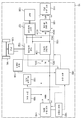
도 1은 제1 실시 형태의 연료 전지 차량의 구성을 도시하는 개략도이다.
도 2는 제어 장치에 의한 SOC 보정 제어를 설명하기 위한 흐름도이다.
도 3은 SOC 보정 제어 맵을 설명하기 위한 도면이다.
도 4는 이차 전지 어시스트 제어 맵을 설명하기 위한 도면이다.
도 5는 연료 전지에 있어서의 발전 효율과 출력 전압과의 관계를 예시한 설명도이다.
도 6은 제2 실시 형태의 SOC 보정 제어 맵을 설명하기 위한 도면이다.
도 7은 제2 실시 형태의 이차 전지 어시스트 제어 맵을 설명하기 위한 도면이다.
도 8은 변형예의 SOC 보정 제어 맵을 설명하기 위한 도면이다.BRIEF DESCRIPTION OF THE DRAWINGS The features, advantages, and technical and industrial significance of the present invention will be described with reference to the accompanying drawings, in which like reference numerals refer to like elements throughout.
1 is a schematic view showing a configuration of a fuel cell vehicle according to the first embodiment.
2 is a flowchart for explaining SOC correction control by the control apparatus.
3 is a diagram for explaining the SOC correction control map.
4 is a diagram for explaining a secondary battery assist control map.
5 is an explanatory diagram illustrating the relationship between the power generation efficiency and the output voltage in the fuel cell.
6 is a diagram for explaining an SOC correction control map according to the second embodiment.
7 is a diagram for explaining the secondary battery assist control map of the second embodiment.
8 is a diagram for explaining the SOC correction control map of the modified example.
A. 제1 실시 형태: A. First Embodiment:
도 1은, 제1 실시 형태에 있어서의 연료 전지 차량(10)의 구성을 도시하는 개략도이다. 연료 전지 차량(10)은, 연료 전지(110)와, FC 승압 컨버터(120)와, 파워 컨트롤 유닛(PCU)(130)과, 모터(136)와, 에어콤프레서(ACP)(138)와, 차속 검출부(139)와, 이차 전지(140), SOC 검출부(142)와, FC 보조 기기(150)와, 공조 장치(160)와, 제어 장치(180)와, 차륜(WL)을 구비한다. 연료 전지 차량(10)은, 연료 전지(110) 및 이차 전지(140)로부터 공급되는 전력에 의해 모터(136)를 구동시켜 주행한다. 1 is a schematic view showing a configuration of a
연료 전지(110)는, 반응 가스로서 수소와 산소의 공급을 받아서 발전하는 고체 고분자형 연료 전지이다. 또한, 연료 전지(110)로서는, 고체 고분자형 연료 전지에 한정되지 않고, 다른 다양한 타입의 연료 전지를 채용할 수 있다. 연료 전지(110)는, FC 승압 컨버터(120)를 통하여 고압 직류 배선(DCH)에 접속되고, 고압 직류 배선(DCH)을 통하여 PCU(130)에 포함되는 모터 드라이버(132)에 접속되어 있다. FC 승압 컨버터(120)는, 연료 전지(110)의 출력 전압(VFC)을 모터 드라이버(132)에서 이용 가능한 고압 전압(VH)으로 승압한다. The
모터 드라이버(132)는 삼상 인버터 회로에 의해 구성되고, 모터(136)에 접속되어 있다. 모터 드라이버(132)는, FC 승압 컨버터(120)를 통하여 공급되는 연료 전지(110)의 출력 전력 및 DC/DC 컨버터(134)를 통하여 공급되는 이차 전지(140)의 출력 전력을 삼상 교류 전력으로 변환해서 모터(136)에 공급한다. 모터(136)는, 삼상 코일을 구비하는 동기 모터에 의해 구성되고, 기어 등을 통하여 차륜(WL)을 구동한다. 또한, 모터(136)는 연료 전지 차량(10)의 제동 시에서, 연료 전지 차량(10)의 운동 에너지를 회생시켜 회생 전력을 발생시키는 발전기로서도 기능한다. 차속 검출부(139)는 연료 전지 차량(10)의 차속(Vve)을 검출하고, 제어 장치(180)에 송신한다. The
DC/DC 컨버터(134)는 제어 장치(180)로부터의 구동 신호에 따라서 고압 직류 배선(DCH)의 전압 레벨을 조정하고, 이차 전지(140)의 충전/방전의 상태를 전환한다. 또한, 모터(136)에 있어서 회생 전력이 발생하는 경우에는, 그 회생 전력은 모터 드라이버(132)에 의해 직류 전력으로 변환되고, DC/DC 컨버터(134)를 통하여 이차 전지(140)에 충전된다. The DC /
ACP 드라이버(137)는 삼상 인버터 회로에 의해 구성되고, ACP(138)에 접속되어 있다. ACP 드라이버(137)는 FC 승압 컨버터(120)를 통하여 공급되는 연료 전지(110)의 출력 전력 및 DC/DC 컨버터(134)를 통하여 공급되는 이차 전지(140)의 출력 전력을 삼상 교류 전력으로 변환해서 ACP(138)에 공급한다. ACP(138)는, 삼상 코일을 구비하는 동기 모터에 의해 구성되고, 공급된 전력에 따라서 모터를 구동시켜, 발전에 사용되는 산소(공기)를 연료 전지(110)에 공급한다. The
이차 전지(140)는 전력 에너지를 축적하고, 충전과 방전을 반복할 수 있는 축전 장치이며, 예를 들어, 리튬 이온 전지로 구성할 수 있다. 또한, 이차 전지(140)로서는, 연축 전지, 니켈 카드뮴 전지, 니켈 수소 전지 등 다른 종류의 전지이어도 좋다. 이차 전지(140)는, 저압 직류 배선(DCL)을 통하여 PCU(130)에 포함되는 DC/DC 컨버터(134)에 접속되고, 또한, DC/DC 컨버터(134)를 통하여 고압 직류 배선(DCH)에 접속되어 있다. The
SOC 검출부(142)는 이차 전지(140)의 축전량(SOC)을 검출하고, 제어 장치(180)에 송신한다. 또한, 본 명세서에 있어서 「축전량(SOC)」이란, 이차 전지(140)의 현재의 충전 용량에 대한 충전 잔량의 비율을 의미한다. 이후, SOC 검출부(142)에 의해 검출되는 이차 전지(140)의 축전량(SOC)을 「축전량 Rsoc」라고도 칭한다. SOC 검출부(142)는 이차 전지(140)의 온도(Tba)나, 출력 전압, 출력 전류를 검출하고, 그들 검출값에 기초하여, 축전량(Rsoc)을 검출한다. 또한, 본 실시 형태의 SOC 검출부(142)는, 이차 전지(140)의 온도(Tba)에 대해서도 제어 장치(180)에 송신한다. The
FC 보조 기기(150)와 공조 장치(160)는, 각각, 저압 직류 배선(DCL)에 접속되고, 연료 전지(110)나 이차 전지(140)로부터 공급되는 전력에 의해 구동한다. FC 보조 기기(150)는, 연료 전지(110)에 반응 가스를 공급하는 연료 펌프 및 연료 전지(110)에 냉매를 공급하는 냉매 펌프 등의 연료 전지(110)의 발전을 위한 보조 기기류이다. 공조 장치(160)는 에어컨 등의 공조 기기이다. The FC
제어 장치(180)는, 중앙 처리 장치와 주기억 장치를 구비하는 마이크로컴퓨터에 의해 구성되어 있다. 제어 장치(180)는 운전자에 의한 액셀러레이터 조작 등의 조작을 검출하면, 그 조작 내용에 따라서, 연료 전지(110)의 발전이나 이차 전지(140)의 충방전을 제어한다. 제어 장치(180)는 모터 드라이버(132)와, DC/DC 컨버터(134)에 각각, 액셀러레이터 개방도에 따른 구동 신호를 생성해서 송신한다. 모터 드라이버(132)는 제어 장치(180)의 구동 신호에 따라서, 교류 전압의 펄스 폭을 조정하는 등으로 하여, 모터(136)에 액셀러레이터 개방도에 따른 회전 구동을 시킨다. 제어 장치(180)는 이차 전지 어시스트율과, 이차 전지(140)의 축전량(SOC)과의 관계가 도시된 이차 전지 어시스트 제어 맵과, HV 요구 전력과 이차 전지 출력과의 관계가 도시되어, 시스템의 손실이 최소가 되는 전력 배분이 도시된 맵을 구비하고 있다. 제어 장치(180)는 모터(136)를 액셀러레이터 개방도에 따른 회전 구동시키기 위해 필요한 전력(요구 전력)에 대해, 이차 전지 어시스트 제어 맵으로부터 산출되는 이차 전지 어시스트율과, HV 요구 전력과 이차 전지 출력과의 관계가 도시된 맵(HV 요구 전력-이차 전지 출력 맵)으로부터 산출되는 이차 전지 출력과의 곱에 의해 이차 전지의 출력을 결정한다. 이차 전지 어시스트 제어 맵의 구성에 대해서는 후술한다. The
제어 장치(180)는 SOC 검출부(142)가 검출된 축전량(Rsoc)을 취득하고, 취득한 축전량(Rsoc)에 기초하여, 이차 전지(140)의 축전량이 소정의 범위 내에 수용되도록, 이차 전지(140)의 충방전을 제어한다. 이 제어 장치(180)에 의한 SOC의 검출값에 기초하는 이차 전지(140)의 충방전 제어를 「SOC 보정 제어」라고도 칭한다. 제어 장치(180)는 SOC 피드백 제어를 개시할 때에, 이차 전지(140)의 축전량의 허용 범위를 규정하기 위한 기준이 되는 상한값과 하한값을 미리 설정한다. 제어 장치(180)는 이차 전지(140)의 축전량(SOC)과, 이차 전지(140)의 축전량을 소정의 범위 내로 하기 위해 필요한 충방전량과의 관계가 도시된 SOC 보정 제어 맵을 구비하고 있고, 이 맵을 사용해서, 이차 전지(140)의 충방전량을 결정한다. SOC 보정 제어 맵의 구성에 대해서는 후술한다. The
도 2는, 제어 장치(180)에 의한 SOC 보정 제어를 설명하기 위한 흐름도이다. 제어 장치(180)는 드라이버에 의한 이그니션 ON 등의 특정 조작을 검출하면 SOC 보정 제어를 개시한다. 먼저, 제어 장치(180)는 차속 검출부(139)로부터 차속(Vve)을 취득하고, SOC 검출부(142)로부터 이차 전지(140)의 축전량(Rsoc)을 취득한다(스텝 S110). 본 실시 형태의 제어 장치(180)는, 이때, SOC 검출부(142)로부터 이차 전지(140)의 온도(Tba)도 취득한다. Fig. 2 is a flowchart for explaining SOC correction control by the
적어도 차속(Vve)을 취득한 후, 제어 장치(180)는, 예상 축전 증가량(ΔCsoc)의 추정을 행한다(스텝 S120). 예상 축전 증가량(ΔCsoc)이란, 차속 검출부(139)에 의해 검출된 차속(Vve)에 있어서, 연료 전지 차량(10)을 제동시킨 경우에 얻어지는 회생 전력을 이차 전지(140)에 공급했을 때의 축전량(Rsoc)의 증가량에 상당한다. 바꿔 말하면, 차속(Vve)에 상당하는 연료 전지 차량(10)의 운동 에너지를 모터(136)에 의해 회생시켰을 때의 축전량(Rsoc)의 예상 증가량이다. 이와 같이, 제어 장치(180)는, 연료 전지 차량(10)이 얻어지는 회생 전력을 추정하는 회생량 추정부로서의 기능도 포함하고 있다. 또한, 회생량 추정부로서의 제어 장치(180)는, 예를 들어, 네비게이터 정보에 의해 이제부터 내리막길이 이어질 때에는, 그 정보로부터 연료 전지 차량(10)이 얻어지는 회생 전력을 추정해도 좋다. After acquiring at least the vehicle speed Vve, the
본 실시 형태에서는, 예상 축전 증가량(ΔCsoc)은 검출된 차속(Vve)을 사용해서, 하기의 수학식 1에 의해 산출된다. In the present embodiment, the predicted power generation increase amount? Csoc is calculated by the following formula (1) using the detected vehicle speed Vve.

여기서, Wve는, 연료 전지 차량(10)의 중량이다. ErcㆍEtrㆍEch는, 연료 전지 차량(10)의 운동 에너지가 이차 전지(140)에 축적되는 전기 에너지(회생 에너지)가 될 때까지의 사이의 에너지 효율이며, 기지의 값으로서 설정되어 있다. Erc는 모터(136)에 있어서 운동 에너지를 회생 에너지로 변환할 때의 효율(회생 회수 효율)이다. Etr은 모터(136)에서 발생한 회생 전력이 모터 드라이버(132)나 DC/DC 컨버터(134)를 통과할 때의 효율이다. Ech는 회생 전력을 이 차 전지(140)에 충전할 때의 효율(충전 효율)이다. Uco는 이차 전지(140)에 축적되는 회생 에너지를 이차 전지(140)의 축전량(SOC)으로 환산하기 위한 계수(단위 환산 계수)이다. Win은 이차 전지(140)의 온도(Tba)에 따라서 변화되는 이차 전지(140)의 충전 능력에 대응시키기 위한 충전 제한율이며, SOC 검출부(142)에 의해 검출된 온도(Tba)로부터 일의적으로 산출된다. ΔCsoc의 산출식에 Win을 포함함으로써, 이차 전지(140)의 충전 능력에 제약이 있는 경우에는, 예상 축전 증가량(ΔCsoc)을 저감시킬 수 있다.Here, Wve is the weight of the
예상 축전 증가량(ΔCsoc)을 추정한 후, 제어 장치(180)는 예상 축전 증가량(ΔCsoc)이 가드값으로서 설정되어 있는 상한값(Tsoc)보다 큰지 여부의 판정을 행한다(스텝 S130). 상한값(Tsoc)이란, 예상 축전 증가량(ΔCsoc)과, 그 후의 제동에 의해 얻어지는 축전량(Rsoc)의 실제의 증가량과의 오차에 의해 과도한 SOC 저하나 이차 전지(140)가 열화되는 것을 억제하기 위한 값이다. 추정한 예상 축전 증가량(ΔCsoc)이 상한값(Tsoc)보다 큰 경우, 제어 장치(180)는 상한값(Tsoc)을 축전 증가량(ΔCsoc)으로서 설정한다(스텝 S140). 이에 의해, 실제로 차량의 제동 시에 얻어진 회생 에너지가 예상보다도 대폭으로 작았던 경우라도, 축전량(Rsoc)이 축전량의 허용 하한값을 하회하기 어렵게 할 수 있다. 이에 의해, 이차 전지(140)의 보호를 도모할 수 있다. After estimating the estimated power generation increase amount [Delta] Csoc, the
예상 축전 증가량(ΔCsoc)을 추정한 후, 제어 장치(180)는 예상 축전 증가량(ΔCsoc)과, 축전량(Rsoc)을 사용해서, 가상 축전량(Vsoc)의 산출을 행한다(스텝 S150). 가상 축전량(Vsoc)은 이차 전지(140)의 실제 축전량(Rsoc)에, 장래 회생 에너지로서 회수된다고 예상되는 연료 전지 차량(10)의 운동 에너지를 예상한 이차 전지(140)의 가상 축전량이다. 가상 축전량(Vsoc)은, 이하의 수학식 2에 의해 산출된다. After estimating the predicted power generation increase amount? Csoc, the
![]()
![]()
제어 장치(180)는 산출한 가상 축전량(Vsoc)을 SOC 보정 제어 맵에 적용함으로써, 이차 전지(140)의 충방전을 행하는지 여부 및 충방전을 행하는 경우의 충방전량을 결정한다. 구체적으로는, 제어 장치(180)는, 먼저, 가상 축전량(Vsoc)이, 하기의 수학식 3을 만족하는지 여부, 즉, 가상 축전량(Vsoc)이, 축전량의 상한값(Uth)과 하한값(Dth) 사이에 있는지 여부의 판정을 행한다(스텝 S160). The
![]()
![]()
가상 축전량(Vsoc)이 상한값(Uth)과 하한값(Dth) 사이에 있는 경우에는, 가상 축전량(Vsoc)이 목표로 하는 축전량 부근에 있으므로, 제어 장치(180)는 이차 전지(140)의 축전량을 조정하기 위한 충방전을 행하지 않는다. 그리고, 제어 장치(180)는, 다시, 스텝 S110의 처리를 실시한다. 한편, 가상 축전량(Vsoc)이 상한값(Uth)과 하한값(Dth) 사이에 없는 경우에는, 가상 축전량(Vsoc)을 목표로 하는 축전량에 근접하기 위해, 이차 전지(140)의 충방전을 행한다(스텝 S170). 이차 전지(140)의 충방전량은, 가상 축전량(Vsoc)과 SOC 보정 제어 맵으로부터 결정된다. 그 후, 제어 장치(180)는, 다시, 스텝 S110의 처리를 실시한다. 이와 같이, 제어 장치(180)는, 도 2의 각 처리를 반복 행함으로써, 가상 축전량(Vsoc)이 상한값(Uth)과 하한값(Dth) 사이에 유지되도록 이차 전지(140)의 충방전을 행한다. When the virtual storage amount Vsoc is between the upper limit value Uth and the lower limit value Dth and the virtual storage amount Vsoc is near the target storage amount, Charge and discharge for regulating the electric storage amount are not performed. Then, the
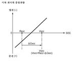
도 3은 SOC 보정 제어 맵을 설명하기 위한 도면이다. SOC 보정 제어 맵에는 이차 전지(140)의 축전량(SOC)과, SOC 보정을 위한 이차 전지(140)의 충방전량과의 관계가 도시되어 있다. 도 3의 횡축은 이차 전지(140)의 축전량(SOC)을 도시하고 있고, 종축은 이차 전지(140)의 충방전량을 도시하고 있다. 또한, 도 3에는 이차 전지(140)의 실제 축전량(Rsoc)과, 산출된 가상 축전량(Vsoc)이 예시되어 있다. 3 is a diagram for explaining the SOC correction control map. The SOC correction control map shows the relationship between the storage amount SOC of the
제어 장치(180)는 SOC 보정 제어 맵에 있어서의 가상 축전량(Vsoc)의 위치에 기초하여, 이차 전지(140)의 충방전 제어를 행한다. 도 3에서는, 가상 축전량(Vsoc)은 상한값(Uth)과 하한값(Dth) 사이에 있으므로, 제어 장치(180)는 이차 전지(140)의 충방전을 행하지 않는다. 한편, 종래와 같이, 실제 축전량(Rsoc)에 기초하여 이차 전지(140)의 충방전 제어를 행한 경우에는, 축전량(Rsoc)은 하한값(Dth)보다도 작으므로, 이차 전지(140)에의 충전이 행해진다. 이와 같이, 가상 축전량(Vsoc)에 의해 제어를 행함으로써, 회생 전력에 의한 이차 전지(140)의 축전량의 증가를 예상할 수 있는 경우에는, 예상할 수 없는 경우보다도 이차 전지(140)에의 충전을 억제할 수 있다. 이에 의해, 연료 전지(110)가 불필요한 발전을 억제하여 연비의 향상을 도모할 수 있다. 또한, 그 후의 회생 전력의 공급 시에, 그 불필요한 발전에 의해 SOC가 상승하여, SOC가 방전측(도 3의 우측)으로 흔들림으로써 효율이 좋은 전력 분배를 따른 이차 전지로부터의 출력 공급으로 되지 않고 연비 악화되는 장면을 저감할 수 있다. 또한, 회생 전력에 의한 이차 전지의 축전량의 증가를 예상할 수 있는 경우에는, 이차 전지(140)를 보다 적극적으로 방전시킬 수 있다. 이에 의해, 이차 전지(140)로부터 모터(136)에의 전력 공급량을 증가시킴으로써 연료 전지(110)에 의한 발전량을 억제하여, 연료 전지 차량(10)의 연비의 향상을 도모할 수 있다. The
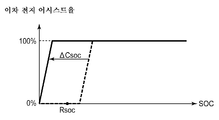
도 4는 이차 전지 어시스트 제어 맵을 설명하기 위한 도면이다. 이차 전지 어시스트 제어 맵에는, 이차 전지(140)의 축전량(SOC)과, 이차 전지 어시스트율과의 관계가 도시되어 있다. 이차 전지(140)의 출력은 이차 전지 어시스트율과, HV 요구 전력-이차 전지 출력 맵으로부터 산출되는 이차 전지 출력과의 곱에 의해 결정된다. 예를 들어, 이차 전지 어시스트율이 0%일 때는, 연료 전지(110)로부터만 전력이 모터(136)에 공급되는 것을 의미한다. 도 4의 횡축은 이차 전지(140)의 축전량(SOC)을 나타내고 있고, 종축은 이차 전지 어시스트율을 나타내고 있다. 또한, 도 4에는 이차 전지(140)의 실제 축전량(Rsoc)과, 산출된 가상 축전량(Vsoc)이 예시되고, 또한, SOC 보정 제어 맵이 파선으로 예시되어 있다. 4 is a diagram for explaining a secondary battery assist control map. The secondary battery assist control map shows the relationship between the storage amount (SOC) of the
제어 장치(180)는 이차 전지 어시스트 제어 맵에 있어서의 가상 축전량(Vsoc)의 위치에 기초하여, 이차 전지 어시스트율을 결정한다. 즉, 도 4에서는 가상 축전량(Vsoc)의 위치로부터, 이차 전지 어시스트율이 100%가 된다. 즉, 이차 전지(140)로부터만 전력이 모터(136)에 공급되고, 연료 전지(110)로부터 모터(136)에 전력은 공급되지 않는다. 한편, 종래와 같이, 실제 축전량(Rsoc)에 기초하여 이차 전지 어시스트율을 결정한 경우에는, 도 4에서는 이차 전지 어시스트율은 0%가 된다. 즉, HV 요구 전력-이차 전지 출력 맵으로부터 산출되는 이차 전지 출력이 이차 전지(140)의 출력이 된다. 이와 같이, 가상 축전량(Vsoc)에 기초하여 어시스트율을 결정함으로써, 회생 전력에 의한 이차 전지(140)의 축전량의 증가를 예상할 수 있는 경우에는, 예상할 수 없는 경우보다도 이차 전지 어시스트율을 높게 할 수 있다. 이에 의해, 연료 전지(110)에 의한 모터(136)에의 전력의 부담 비율을 저감시킬 수 있어, 연비의 향상을 도모할 수 있다. The
도 5는 연료 전지(110)에 있어서의 발전 효율과 출력 전압과의 관계를 예시한 설명도이다. 연료 전지(110)는 비교적 저부하의 출력 전압 V1일 때에 가장 발전 효율이 높아지고, 거기서 부하가 높아질수록 발전 효율이 저하된다. 모터(136)의 요구 전력에 대한 이차 전지(140)의 어시스트율을 높임으로써, 연료 전지(110)의 부하가 경감되므로, 연료 전지(110)를 고효율로 운전할 수 있다. 이에 의해, 연료 전지(110)의 연비의 향상을 도모할 수 있다. 5 is an explanatory diagram illustrating the relationship between the power generation efficiency and the output voltage of the
이상 설명한, 본 실시 형태의 연료 전지 차량(10)에 의하면, 연료 전지 차량(10)이 갖는 운동 에너지를 회생시켰을 때의 이차 전지(140)의 예상 축전 증가량(ΔCsoc)을 고려하여, 이차 전지(140)의 충방전 제어를 행할 수 있으므로, 운동 에너지의 회수 효율의 향상을 도모할 수 있다. 예를 들어, 도 3으로부터 알 수 있는 바와 같이, 회생 전력에 의한 이차 전지(140)의 축전량의 증가를 예상할 수 있는 경우[예상 축전 증가량(ΔCsoc)>>0]에는, 예상할 수 없는 경우[예상 축전 증가량(ΔCsoc)≒0]보다도 연료 전지(110)의 발전에 의한 충전이 억제된다. 이에 의해, 불필요한 발전에 의한 수소 소비를 억제하고, 그 후의 회생 전력의 공급 시에, 이차 전지(140)의 포화에 의한 회생 전력의 파기량을 저감할 수 있다. 즉, 본 실시 형태에 따르면, 이차 전지(140)의 축전량(Rsoc)을 파탄시키지 않고, 충방전량을 증가시킬 수 있다. 또한, 이차 전지(140)의 축전량(Rsoc)으로부터 산출한 가상 축전량(Vsoc)에 기초하여 충방전을 행하는 본 실시 형태의 구성은, SOC 보정 제어 맵의 상한값(Uth)이나 하한값(Dth)의 관리 폭을 변경하는 구성보다도, 제어가 간이하므로, 제어 장치의 간소화를 도모할 수 있다. 또한, 본 실시 형태는, 상한값(Uth)이나 하한값(Dth)의 관리 폭을 변경하지 않으므로, SOC 보정 제어 맵 자체는 기존의 맵을 이용할 수 있다. According to the
B. 제2 실시 형태: B. Second Embodiment:
도 6은, 제2 실시 형태의 SOC 보정 제어 맵을 설명하기 위한 도면이다. 제1 실시 형태에서는, 제어 장치(180)는 이차 전지(140)의 실제 축전량(Rsoc)으로부터 가상 축전량(Vsoc)을 산출하고, 산출한 가상 축전량(Vsoc)을 SOC 보정 제어 맵에 적용함으로써 이차 전지(140)의 충방전 제어를 행했다. 제2 실시 형태의 제어 장치(180)는, 수학식 1에 의해 예상 축전 증가량(ΔCsoc)을 추정한 후, 추정한 예상 축전 증가량(ΔCsoc)에 따라서 SOC 보정 제어 맵의 수정을 행한다. 구체적으로는, 도 6에 도시하는 바와 같이, 제어 장치(180)는 SOC 보정 제어 맵에 있어서, 이차 전지(140)의 축전량(SOC)과, SOC 보정을 위한 이차 전지(140)의 충방전량과의 대응 관계를, 예상 축전 증가량(ΔCsoc)의 분만큼 어긋나게 하여(여기서는, 좌측 방향으로 이동시켜) 새롭게 SOC 보정 제어 맵을 작성한다. 제어 장치(180)는 검출된 실제 축전량(Rsoc)을 새롭게 작성된 SOC 보정 제어 맵에 적용함으로써 이차 전지(140)의 충방전 제어를 행한다. 6 is a diagram for explaining the SOC correction control map of the second embodiment. In the first embodiment, the
도 7은, 제2 실시 형태의 이차 전지 어시스트 제어 맵을 설명하기 위한 도면이다. 상술한 제2 실시 형태의 SOC 보정 제어 맵과 마찬가지로, 제어 장치(180)는, 추정한 예상 축전 증가량(ΔCsoc)에 따라서 이차 전지 어시스트 제어 맵의 수정을 행한다. 구체적으로는, 도 7에 도시하는 바와 같이, 제어 장치(180)는 이차 전지 어시스트 제어 맵에 있어서, 이차 전지(140)의 축전량(SOC)과, 이차 전지 어시스트율과의 대응 관계를, 예상 축전 증가량(ΔCsoc)의 분만큼 어긋나게 하여(여기서는, 좌측 방향으로 이동시켜) 새롭게 이차 전지 어시스트 제어 맵을 작성한다. 제어 장치(180)는 검출된 실제 축전량(Rsoc)을 새롭게 작성된 이차 전지 어시스트 제어 맵에 적용함으로써 이차 전지(140)의 어시스트율을 결정한다. 7 is a diagram for explaining the secondary battery assist control map of the second embodiment. Similar to the SOC correction control map of the second embodiment described above, the
이와 같은, 구성이어도, 연료 전지 차량(10)이 갖는 운동 에너지를 회생시켰을 때의 이차 전지(140)의 예상 축전 증가량(ΔCsoc)을 고려하여, 이차 전지(140)의 충방전 제어를 행할 수 있으므로, 운동 에너지의 회수 효율의 향상을 도모할 수 있다. 회생 전력에 의한 이차 전지(140)의 축전량의 증가를 예상할 수 있는 경우에는 연료 전지(110)의 발전에 의한 충전이 억제되기 때문이다. 또한, 이차 전지(140)를 보다 적극적으로 방전시킬 수 있으므로, 이차 전지(140)로부터 모터(136)에의 전력 공급량을 증가시킬 수 있다. 이에 의해, 연료 전지(110)에 의한 발전량을 억제할 수 있어, 연비의 향상을 도모할 수 있다. Even in such a configuration, the charge / discharge control of the
C. 변형예: C. Modifications:
또한, 본 발명은 상기의 실시 형태나 실시예에 한정되는 것이 아니라, 그 요지를 일탈하지 않는 범위에서 다양한 형태에 있어서 실시하는 것이 가능하고, 예를 들어, 다음과 같은 변형도 가능하다. The present invention is not limited to the above-described embodiments and examples but may be carried out in various forms without departing from the gist of the invention. For example, the following modifications are possible.
C-1. 변형예 1: C-1. Modified Example 1:
본 실시 형태에서는, 연료 전지 차량(10)으로서 실현되어 있지만, 본 발명은, 연료 전지를 구비하고 있지 않은 차량에 대해서도 적용이 가능하다. 예를 들어, 본 발명은 하이브리드 차량에도 적용이 가능하다. 이 경우라도, 하이브리드 차량이 갖는 운동 에너지를 회생시켰을 때의 이차 전지 예상 축전 증가량(ΔCsoc)을 고려하여, 이차 전지의 충방전 제어를 행할 수 있으므로, 운동 에너지의 회수 효율의 향상을 도모할 수 있다. 또한, 이차 전지를 보다 적극적으로 방전시킬 수 있으므로, 이차 전지로부터 모터에의 전력 공급량을 증가시킬 수 있다. 이에 의해, 엔진에 의한 발전량을 억제할 수 있어, 연비의 향상을 도모할 수 있다. Although the present embodiment is realized as the
C-2. 변형예 2: C-2. Modified Example 2:
연료 전지 차량(10)은, 차속(Vve)을 검출하는 차속 검출부(139)를 구비하고 있지만, 차속 검출부(139) 대신에, 모터(136)의 회전수나, 모터(136)에 공급되는 전력량 등, 차속(Vve)과 상관성이 있는 파라미터를 검출하는 검출부를 구비하고 있어도 좋다. 또한, 연료 전지 차량(10)은 이차 전지(140)를 구비하고 있지만, 이차 전지(140) 대신에, 캐패시터, 플라이휠, 초전도 코일, 축압기 등 에너지를 전기적으로 축적하여 방전하는 기능을 갖고 있는 장치를 구비하고 있어도 좋다. 또한, 연료 전지 차량(10)은, 차륜(WL)을 구동하는 모터(136)가 연료 전지 차량(10)의 운동 에너지를 회생하는 발전기로서도 기능하고 있지만, 모터(136)와는 별도로 발전기를 구비하고 있어도 좋다. The
C-3. 변형예 3: C-3. Modified Example 3:
본 실시 형태에서는, 제어 장치(180)는 차속(Vve)으로부터, 차속(Vve)에 상당하는 연료 전지 차량(10)의 운동 에너지를 모터(136)에 의해 회생시켰을 때의 축전량(Rsoc)의 예상 증가량[예상 축전 증가량(ΔCsoc)]을 산출한다. 그러나, 제어 장치(180)는 차속(Vve) 이외로부터 예상 축전 증가량(ΔCsoc)을 추정해도 좋다. 예를 들어, 제어 장치(180)는 네비게이터 정보에 의해 이제부터 내리막길이 이어질 때에는, 그 정보로부터 예상 축전 증가량(ΔCsoc)을 추정해도 좋다. In the present embodiment, the
C-4. 변형예 4: C-4. Modified Example 4:
도 8은 변형예의 SOC 보정 제어 맵을 설명하기 위한 도면이다. 제1 실시 형태에서는, 제어 장치(180)는 가상 축전량(Vsoc)이, 축전량의 상한값(Uth)과 하한값(Dth) 사이에 위치하도록 이차 전지(140)의 충방전 제어를 행하는 것으로서 설명했다. 그러나, SOC 보정 제어 맵에는, 축전량의 상한값(Uth)과 하한값(Dth)이 설정되어 있지 않아도 좋다. 이 경우, 제어 장치(180)는 가상 축전량(Vsoc)의 위치에 기초하여, 이차 전지(140)의 충방전 제어를 행한다. 8 is a diagram for explaining the SOC correction control map of the modified example. In the first embodiment, the
Claims (5)
상기 제어부(180)는, 추정한 상기 예상 축전 증가량이, 미리 설정된 상기 예상 축전 증가량의 상한값보다 큰지 여부를 판정하고, 추정한 예상 축전 증가량이 상기 예상 축전 증가량의 상한값보다도 큰 경우에는, 상기 예상 축전 증가량의 상한값과 상기 실제 축전량과의 합계로부터 상기 가상 축전량을 산출하는, 차량. The method according to claim 1,
The control unit (180) determines whether or not the estimated power generation increase amount is larger than an upper limit value of the predicted power generation increase amount set in advance, and when the estimated power generation increase amount is larger than the upper limit value of the predicted power generation increase amount, And the virtual storage amount is calculated from the sum of the upper limit value of the increase amount and the actual storage amount.
상기 모터(136) 및 상기 이차 전지(140)에 전력을 공급 가능한 전력 발생부(110)를 더 구비하고 있고, 상기 제어부(180)는, 상기 전력 발생부(110)를 사용해서 상기 이차 전지(140)의 충전을 행함과 함께, 상기 이차 전지(140) 및 상기 전력 발생부(110)로부터 상기 모터에 공급되는 전력의 제어를 행하는, 차량. 3. The method according to claim 1 or 2,
The control unit 180 may further include a power generation unit 110 capable of supplying power to the motor 136 and the secondary battery 140. The control unit 180 may control the power generation unit 110, 140) and controls the power supplied from the secondary battery (140) and the power generation unit (110) to the motor.
상기 차량의 속도를 검출하는 속도 검출부(139)를 더 구비하고 있고, 상기 제어부(180)는, 상기 속도 검출부(139)에 의해 검출된 상기 차량의 속도를 사용해서, 상기 속도에 상당하는 상기 차량의 운동 에너지를 상기 전력 회생부(130)에 의해 회생시킨 경우에 얻어지는 전력을 상기 차량이 얻어지는 회생 전력으로서 추정함과 함께, 상기 가상 축전량이, 미리 설정된 상기 가상 축전량의 상한값과 하한값 사이가 되도록, 상기 이차 전지(140)의 충방전을 행하는, 차량. 4. The method according to any one of claims 1 to 3,
The control unit 180 further includes a speed detection unit 139 that detects the speed of the vehicle and the control unit 180 controls the speed of the vehicle based on the speed of the vehicle detected by the speed detection unit 139, Is estimated as the regenerative electric power obtained by the vehicle and the electric power obtained when the virtual electric storage amount is between the upper limit value and the lower limit value of the preset virtual storage amount , And the secondary battery (140) is charged and discharged.
Applications Claiming Priority (2)
| Application Number | Priority Date | Filing Date | Title |
|---|---|---|---|
| JP2014225678A JP6319053B2 (en) | 2014-11-06 | 2014-11-06 | Vehicle driven by motor, and control method of charge / discharge of secondary battery mounted on vehicle |
| JPJP-P-2014-225678 | 2014-11-06 |
Related Child Applications (1)
| Application Number | Title | Priority Date | Filing Date |
|---|---|---|---|
| KR1020180027549A Division KR102007360B1 (en) | 2014-11-06 | 2018-03-08 | Vehicle driven by motor and control method of charging and discharging of secondary battery provided in vehicle |
Publications (1)
| Publication Number | Publication Date |
|---|---|
| KR20160054398A true KR20160054398A (en) | 2016-05-16 |
Family
ID=55803493
Family Applications (2)
| Application Number | Title | Priority Date | Filing Date |
|---|---|---|---|
| KR1020150147090A KR20160054398A (en) | 2014-11-06 | 2015-10-22 | Vehicle driven by motor and control method of charging and discharging of secondary battery provided in vehicle |
| KR1020180027549A KR102007360B1 (en) | 2014-11-06 | 2018-03-08 | Vehicle driven by motor and control method of charging and discharging of secondary battery provided in vehicle |
Family Applications After (1)
| Application Number | Title | Priority Date | Filing Date |
|---|---|---|---|
| KR1020180027549A KR102007360B1 (en) | 2014-11-06 | 2018-03-08 | Vehicle driven by motor and control method of charging and discharging of secondary battery provided in vehicle |
Country Status (5)
| Country | Link |
|---|---|
| US (1) | US10099557B2 (en) |
| JP (1) | JP6319053B2 (en) |
| KR (2) | KR20160054398A (en) |
| CN (1) | CN105591169B (en) |
| DE (1) | DE102015118112B4 (en) |
Families Citing this family (11)
| Publication number | Priority date | Publication date | Assignee | Title |
|---|---|---|---|---|
| JP6789866B2 (en) * | 2017-03-28 | 2020-11-25 | 京セラ株式会社 | Power storage device and power management system |
| JP6855902B2 (en) * | 2017-04-24 | 2021-04-07 | トヨタ自動車株式会社 | Fuel cell system |
| CN107171418A (en) * | 2017-07-26 | 2017-09-15 | 深圳天珑无线科技有限公司 | Data processing method, device and non-transitory computer-readable medium |
| WO2019120570A1 (en) * | 2017-12-22 | 2019-06-27 | Volvo Truck Corporation | A method of controlling a state of charge operation range of a vehicle electrical system |
| CN110182105A (en) * | 2018-10-18 | 2019-08-30 | 丰疆智能科技研究院(常州)有限公司 | Tractor and its energy supply management system and application |
| JP7159812B2 (en) * | 2018-11-27 | 2022-10-25 | トヨタ自動車株式会社 | fuel cell vehicle |
| CN109849678A (en) * | 2019-01-25 | 2019-06-07 | 云南航天神州汽车有限公司 | A kind of electric car regenerative braking safety control |
| JP7207007B2 (en) * | 2019-02-26 | 2023-01-18 | トヨタ自動車株式会社 | vehicle controller |
| JP7135984B2 (en) * | 2019-04-12 | 2022-09-13 | トヨタ自動車株式会社 | Fuel cell system and control method |
| JP7409905B2 (en) * | 2020-02-28 | 2024-01-09 | 株式会社シマノ | Control device for human-powered vehicles |
| GB2617698A (en) * | 2022-04-11 | 2023-10-18 | Hydrogen Vehicle Systems Ltd | A system for the optimization of powertrain subsystems to account for cargo load variations in a hybrid electric vehicle |
Family Cites Families (29)
| Publication number | Priority date | Publication date | Assignee | Title |
|---|---|---|---|---|
| JP3882485B2 (en) | 2000-09-04 | 2007-02-14 | 日産自動車株式会社 | Fuel cell vehicle |
| JP4051911B2 (en) * | 2001-10-03 | 2008-02-27 | 日産自動車株式会社 | Control device for hybrid vehicle |
| JP4100335B2 (en) | 2003-11-28 | 2008-06-11 | 株式会社エクォス・リサーチ | Drive control device and hybrid vehicle |
| JP2006248431A (en) * | 2005-03-11 | 2006-09-21 | Nissan Motor Co Ltd | Onboard battery apparatus, and method for controlling its temperature |
| JP4202379B2 (en) * | 2006-10-11 | 2008-12-24 | トヨタ自動車株式会社 | HYBRID VEHICLE, HYBRID VEHICLE CONTROL METHOD, PROGRAM FOR CAUSING COMPUTER TO EXECUTE THE CONTROL METHOD, AND COMPUTER-READABLE RECORDING MEDIUM CONTAINING THE PROGRAM |
| JP4353305B2 (en) | 2008-03-21 | 2009-10-28 | トヨタ自動車株式会社 | Power control circuit |
| JP5332907B2 (en) * | 2009-05-27 | 2013-11-06 | 日産自動車株式会社 | Battery charging control device for electric vehicle |
| US8228035B2 (en) * | 2009-05-29 | 2012-07-24 | GM Global Technology Operations LLC | Regeneration capacity control method for a battery |
| JP5570782B2 (en) | 2009-10-16 | 2014-08-13 | 三洋電機株式会社 | POWER SUPPLY DEVICE, VEHICLE EQUIPPED WITH THE SAME, AND CHARGING / DISCHARGE CONTROL METHOD FOR POWER SUPPLY DEVICE |
| CN102405150B (en) | 2010-05-27 | 2014-04-09 | 丰田自动车株式会社 | Fuel cell system |
| JP2012070554A (en) * | 2010-09-24 | 2012-04-05 | Ihi Corp | Riding type lawn mowing vehicle and control method thereof |
| JP5048824B2 (en) * | 2010-10-25 | 2012-10-17 | 三菱電機株式会社 | Vehicle power generation control device |
| JP2012106652A (en) * | 2010-11-18 | 2012-06-07 | Toyota Motor Corp | Vehicle control device |
| WO2012093545A1 (en) * | 2011-01-05 | 2012-07-12 | 三菱電機株式会社 | Motor control device |
| JP2013005485A (en) * | 2011-06-13 | 2013-01-07 | Nissan Motor Co Ltd | Charge control device of vehicle battery |
| US9751424B2 (en) | 2011-07-14 | 2017-09-05 | Ford Global Technologies, Llc | Method and system for determining a target state of charge to charge a battery in a vehicle using external electric power |
| JP5803507B2 (en) | 2011-09-28 | 2015-11-04 | トヨタ自動車株式会社 | Hybrid vehicle control device and hybrid vehicle |
| JP5765194B2 (en) * | 2011-11-08 | 2015-08-19 | トヨタ自動車株式会社 | Vehicle and vehicle control method |
| JP5652378B2 (en) * | 2011-11-17 | 2015-01-14 | 株式会社デンソー | Battery control device |
| JP5803849B2 (en) * | 2012-08-27 | 2015-11-04 | トヨタ自動車株式会社 | Power storage system |
| KR101448755B1 (en) * | 2012-12-18 | 2014-10-08 | 현대자동차 주식회사 | Method and system for controlling speed reduction while coasting of electric vehicle |
| EP2847027A4 (en) * | 2012-12-18 | 2015-12-30 | Emerald Automotive Llc | Optimization of extended range electric vehicle |
| JP6051857B2 (en) * | 2012-12-28 | 2016-12-27 | コベルコ建機株式会社 | Construction machinery |
| US9043085B2 (en) * | 2013-01-11 | 2015-05-26 | Johnson Controls Technology Company | Vehicle accessory load controller and method |
| JP2014150704A (en) | 2013-02-04 | 2014-08-21 | Toyota Industries Corp | Apparatus and method for charging |
| US9266529B2 (en) * | 2013-03-05 | 2016-02-23 | Toyota Motor Engineering & Manufacturing North America, Inc. | Known route HV control compensation |
| KR20150133539A (en) * | 2014-05-20 | 2015-11-30 | 현대자동차주식회사 | Regenerative braking method for vehicle and apparatus of the same |
| US9889764B2 (en) * | 2015-09-17 | 2018-02-13 | Hyundai Motor Company | Apparatus and method for controlling battery of green car |
| JP6249003B2 (en) * | 2015-09-30 | 2017-12-20 | トヨタ自動車株式会社 | Control device for hybrid vehicle |
-
2014
- 2014-11-06 JP JP2014225678A patent/JP6319053B2/en active Active
-
2015
- 2015-10-22 KR KR1020150147090A patent/KR20160054398A/en active Application Filing
- 2015-10-23 DE DE102015118112.6A patent/DE102015118112B4/en active Active
- 2015-10-28 US US14/925,004 patent/US10099557B2/en active Active
- 2015-11-04 CN CN201510740507.5A patent/CN105591169B/en active Active
-
2018
- 2018-03-08 KR KR1020180027549A patent/KR102007360B1/en active IP Right Grant
Also Published As
| Publication number | Publication date |
|---|---|
| US10099557B2 (en) | 2018-10-16 |
| JP2016092987A (en) | 2016-05-23 |
| US20160129804A1 (en) | 2016-05-12 |
| DE102015118112A1 (en) | 2016-05-12 |
| CN105591169B (en) | 2019-04-05 |
| KR20180030403A (en) | 2018-03-22 |
| KR102007360B1 (en) | 2019-08-05 |
| CN105591169A (en) | 2016-05-18 |
| JP6319053B2 (en) | 2018-05-09 |
| DE102015118112B4 (en) | 2023-03-02 |
Similar Documents
| Publication | Publication Date | Title |
|---|---|---|
| KR102007360B1 (en) | Vehicle driven by motor and control method of charging and discharging of secondary battery provided in vehicle | |
| KR101742392B1 (en) | Method for controlling external electric power supply system of fuel cell-mounted vehicle, and external electric power supply system | |
| US9421867B2 (en) | Electric vehicle | |
| US8639413B2 (en) | Vehicle power supply system and method for controlling the same | |
| KR101924252B1 (en) | Electric power supply device | |
| US8600599B2 (en) | Fuel cell vehicle | |
| JP4774430B2 (en) | Electric vehicle and power storage device control method | |
| JP5720538B2 (en) | Storage device control device | |
| JPWO2016151695A1 (en) | Vehicle power control device | |
| US20150343909A1 (en) | Charge/discharge system | |
| US8501360B2 (en) | Fuel cell output control device | |
| JP5510283B2 (en) | Power storage unit protection system for vehicles | |
| CN105633437A (en) | Fuel cell system, fuel cell vehicle, and method of controlling fuel cell system | |
| EP2789493B1 (en) | Apparatus for cooling electric storage apparatus, and method for controlling cooling of electric storage apparatus | |
| US20150336466A1 (en) | Charge/discharge system | |
| JP2012075280A (en) | Power supply device for vehicle | |
| CN107097647A (en) | Method of supplying power to and electric power system | |
| CN104067438A (en) | Control device for lithium-ion battery and recovery method for lithium-ion battery | |
| JP2007300774A (en) | Controller of fuel cell vehicle | |
| JP2019170022A (en) | vehicle | |
| JPH09308117A (en) | Battery residual capacity measuring device | |
| JP2001157307A (en) | Control device of hybrid vehicle | |
| JP3772875B2 (en) | Control device for hybrid vehicle | |
| JP3772876B2 (en) | Control device for hybrid vehicle | |
| JP5169479B2 (en) | Vehicle control device |
Legal Events
| Date | Code | Title | Description |
|---|---|---|---|
| A201 | Request for examination | ||
| E902 | Notification of reason for refusal | ||
| E601 | Decision to refuse application | ||
| E801 | Decision on dismissal of amendment | ||
| A107 | Divisional application of patent |