KR20160053983A - Test system having a compliant actuator assembly and iteratively obtained drive - Google Patents
Test system having a compliant actuator assembly and iteratively obtained drive Download PDFInfo
- Publication number
- KR20160053983A KR20160053983A KR1020167009132A KR20167009132A KR20160053983A KR 20160053983 A KR20160053983 A KR 20160053983A KR 1020167009132 A KR1020167009132 A KR 1020167009132A KR 20167009132 A KR20167009132 A KR 20167009132A KR 20160053983 A KR20160053983 A KR 20160053983A
- Authority
- KR
- South Korea
- Prior art keywords
- test
- drive signal
- error
- response
- physical
- Prior art date
Links
Images


Classifications
-
- G—PHYSICS
- G01—MEASURING; TESTING
- G01M—TESTING STATIC OR DYNAMIC BALANCE OF MACHINES OR STRUCTURES; TESTING OF STRUCTURES OR APPARATUS, NOT OTHERWISE PROVIDED FOR
- G01M17/00—Testing of vehicles
-
- G—PHYSICS
- G05—CONTROLLING; REGULATING
- G05B—CONTROL OR REGULATING SYSTEMS IN GENERAL; FUNCTIONAL ELEMENTS OF SUCH SYSTEMS; MONITORING OR TESTING ARRANGEMENTS FOR SUCH SYSTEMS OR ELEMENTS
- G05B17/00—Systems involving the use of models or simulators of said systems
- G05B17/02—Systems involving the use of models or simulators of said systems electric
Abstract
테스트 시스템 및 방법은 테스트 시편(18)에 부하를 부가하기 위하여 테스트 구동 신호를 컴플라이언트 액추에이터 조립체(150)를 갖는 물리적 테스트 리그(10, 200)에 인가하는 것을 포함한다. 물리적 테스트 리그(10) 및 테스트 구동 신호에 대한 테스트 시편(18)의 실제 응답 신호가 얻어지며 그리고 실제 응답 신호 및 선택된 응답 신호의 함수로서의 오류가 계산된다. 만일, 오류가 선택된 임계값에 도달하지 않으면, 오류 그리고 완화 이득 계수에 기초한 새로운 구동 신호가 얻어진다. 오류가 선택된 임계값에 도달할 때까지 새로운 구동 신호가 얻어지며 그리고 가해진다. The test system and method includes applying a test drive signal to a physical test rig 10, 200 having a compliant actuator assembly 150 to add a load to the test specimen 18. The actual response signal of the physical test rig 10 and the test specimen 18 for the test drive signal is obtained and an error is calculated as a function of the actual response signal and the selected response signal. If the error does not reach the selected threshold, a new drive signal is obtained based on the error and the relaxation gain factor. A new drive signal is obtained and applied until the error reaches the selected threshold value.
Description
본 출원은 2013년 9월 9일자로 출원된 미국 예비특허출원 제61/875,645호를 우선권으로 주장한다. This application claims priority from U.S. Provisional Patent Application No. 61 / 875,645 filed on September 9, 2013.
본 발명은 시스템, 기계 또는 공정의 제어에 관한 것이다. 특히, 본 발명은 진동 또는 다른 제어된 시스템에 대한 입력으로서 구동 신호를 발생시키기 위하여 사용될 모델을 계산하는 것에 관한 것이다. The present invention relates to the control of a system, machine or process. In particular, the present invention relates to calculating a model to be used to generate a drive signal as an input to a vibration or other controlled system.
테스트 시편에 가해진 부하 및/또는 움직임을 시뮬레이션할 수 있는 진동 시스템이 일반적으로 공지되어 있다. 진동 시스템은 제품 개발에 매우 효과적이기 때문에 성능 평가, 내구성 테스트 그리고 다양한 다른 목적을 위하여 널리 사용된다. 예를 들어, 자동차, 모터사이클 등의 개발에 있어 차량 또는 그의 하부 구조를, 도로 또는 테스트 트랙과 같은 작동 조건을 시뮬레이션하는 실험 환경을 겪게 하는 것이 상당히 흔하다. 작동 환경을 재현하도록 진동 시스템에 가해질 수 있는 구동 신호를 성장시키기 위하여 실험실 내에서의 물리적 시뮬레이션은 잘 알려진 데이터 습득 및 분석 방법을 포함한다. 이 방법은 동작 환경의 물리적 입력부에 대해 "원격" 트랜스듀서를 차량에 장착하는 단계를 포함한다. 통상적인 원격 트랜스듀서는 관심있는 작동 환경을 암시적으로 규정하는 스트레인 게이지(strain guage), 가속도계 그리고 변위 센서를 포함하지만, 이에 한정되는 것은 아니다. 원격 트랜스듀서 응답(내부 하중 및/또는 움직임)이 기록되는 동안, 차량은 동일한 작동 환경에서 구동된다. 진동 시스템에 장착된 차량을 시뮬레이션하는 동안 기록된 원격 트랜스듀서 응답을 연구실 내의 차량 상에 재현하도록 진동 시스템의 액추에이터가 구동된다. A vibration system capable of simulating the load and / or motion applied to a test specimen is generally known. Because vibration systems are very effective in product development, they are widely used for performance evaluation, durability testing and various other purposes. For example, in the development of automobiles, motorcycles, etc., it is quite common to have a vehicle or its infrastructure undergo an experimental environment that simulates operating conditions, such as roads or test tracks. Physical simulations within a laboratory to grow drive signals that can be applied to a vibrating system to reproduce the operating environment include well known data acquisition and analysis methods. The method includes the step of mounting a "remote" transducer in the vehicle to a physical input of the operating environment. Conventional remote transducers include, but are not limited to, strain gauges, accelerometers, and displacement sensors that implicitly define the operating environment of interest. While a remote transducer response (internal load and / or motion) is recorded, the vehicle is driven in the same operating environment. An actuator of the vibration system is driven to reproduce the recorded remote transducer response on the vehicle in the laboratory while simulating the vehicle mounted on the vibration system.
그러나, 시뮬레이션된 실험이 일어날 수 있기 전에, 진동 시스템에 대한 입력 구동 신호와 원격 트랜스듀서의 응답 사이의 관계가 연구실에서 특징지어져야 한다. 전형적으로, 이 "시스템 식별(system identification)" 절차는 완전한 물리적 시스템(예를 들어, 진동 시스템, 테스트 시편 및 원격 트랜스듀서; 이하 "물리적 시스템"이라 함)의 각각의 모델 또는 전달 함수를 획득하는 것; 물리적 시스템의 역 모델 또는 역 전달 함수를 계산하는 것; 이 역모델 또는 역전달 함수를 사용하여 진동 시스템을 위한 적절한 구동 신호를 반복적으로 취득하고 작동 환경에서 찾아지는 바와 같은 연구실 상황에서의 테스트 시편 상에서 원격 트랜스듀서로부터의 동일한 응답을 실질적으로 획득하는 것을 포함한다.However, before a simulated experiment can occur, the relationship between the input drive signal to the oscillating system and the response of the remote transducer must be characterized in the laboratory. Typically, this "system identification" procedure is used to obtain each model or transfer function of a complete physical system (e.g., vibration system, test specimen, and remote transducer that; Computing an inverse model or inverse transfer function of the physical system; Repeatedly acquiring an appropriate drive signal for the vibration system using this inverse model or inverse transfer function and substantially obtaining the same response from the remote transducer on a test specimen in a laboratory situation as found in an operating environment do.
본 기술 분야의 지식을 가진 자가 인식할 바와 같이, 원격 트랜스듀서가 테스트 시스템 입력부로부터 물리적으로 떨어져 있지 않을 때(예를 들어, "원격" 트랜스듀서가 진동 시스템 컨트롤러의, 힘 또는 움직임과 같은 피드백 변수인 경우), 적절한 구동 신호를 획득하는 이 과정은 변하지 않는다.It will be appreciated by those skilled in the art that when a remote transducer is not physically separated from a test system input (e.g., a "remote" , This process of obtaining an appropriate drive signal remains unchanged.
진동 시스템을 위한 구동 신호를 얻기 위한 위에서 설명된 시스템과 방법이 실질적인 성공을 누리고 있을지라도, 이러한 시스템을 연속적으로 개선할 필요가 있다. 특히, 구동 신호를 얻기 위하여 물리적 시스템의 모델 그리고 방법을 개선할 필요가 있다. Although the systems and methods described above for obtaining drive signals for an oscillating system have enjoyed substantial success, there is a continuing need to improve such systems. In particular, there is a need to improve the model and method of the physical system to obtain drive signals.
이 요약 및 개념은 상세한 설명에서 이하에서 더 설명되는 간략한 형태의 개념의 선택을 도입하기 위하여 제공된다. 이 요약 및 개념은 청구된 대상물의 핵심 특징 또는 필수적인 특징을 확인하도록 의도된 것이 아니며 또한 이들은 청구된 대상물의 범위를 결정하는데 도움을 주는 것으로 사용되도록 의도된 것은 아니다. 청구된 대상물은 발명의 배경 설명에서 언급된 어떠한 또는 모든 단점을 해결하는 실행을 제한하는 것은 아니다. This summary and concepts are presented to introduce a selection of the concepts in a simplified form that are further described below in the Detailed Description. The summary and concept are not intended to identify key features or essential features of the claimed subject matter, nor are they intended to be used as an aid in determining the scope of the claimed subject matter. The claimed subject matter is not intended to limit the practice of solving any or all of the drawbacks mentioned in the background of the invention.
본 발명의 제 1 태양은 구동 신호에 반응하는 컴플라이언트 액추에이터 조립체를 갖는 물리적 리그를 포함하는 테스트 시스템이며, 여기서 컴플라이언트 액추에이터 조립체는 자신에 작동적으로 연결된 테스트 시편에도 반응한다. 비일시적 컴퓨터 저장 장치가 제공되며 그리고 비일시적 컴퓨터 저장 장치는 프로세서와 함께 작동하도록 구성되어 물리적 테스트 리그에 테스트 구동 신호를 가하기 위하여 저장된 명령을 실행한다. 물리적 테스트 리그 및 테스트 구동 신호에 대한 테스트 시편의 실제 응답 신호가 얻어지며 그리고 실제 응답 신호 및 선택된 응답 신호의 함수로서의 오류가 계산된다. 오류가 선택된 임계값에 도달하지 않으면, 오류와 완화 이득 계수에 기초한 새로운 구동 신호가 획득된다. 오류가 선택된 임계값에 도달할 때까지 새로운 테스트 구동 신호가 얻어지고 인가된다.A first aspect of the present invention is a test system comprising a physical rig having a compliant actuator assembly responsive to a drive signal, wherein the compliant actuator assembly is also responsive to a test specimen operatively connected to the compliant actuator assembly. A non-volatile computer storage device is provided and the non-volatile computer storage device is configured to operate with the processor to execute the stored instructions to apply a test drive signal to the physical test rig. The actual response signal of the test specimen for the physical test rig and the test drive signal is obtained and an error is calculated as a function of the actual response signal and the selected response signal. If the error does not reach the selected threshold, a new drive signal based on the error and the mitigation gain factor is obtained. A new test drive signal is obtained and applied until the error reaches the selected threshold value.
제 2 태양은 테스트 시편에 부하를 부여하기 위한 컴플라이언트 액추에이터 조립체를 갖는 물리적 테스트 리그에 테스트 구동 신호를 인가하는 것을 포함하는 테스트 시스템 작동 방법이다. 테스트 구동 신호에 대한 물리적 테스트 리그 그리고 테스트 시편의 실제 응답 신호가 얻어지며, 그리고 실제 응답 신호와 선택된 응답 신호의 함수로서의 오류가 계산된다. 오류가 선택된 임계값에 도달하지 않으면, 오류와 완화 이득 계수에 기초한 새로운 구동 신호가 얻어진다. 오류가 선택된 임계값에 도달할 때까지 새로운 구동 신호가 얻어지고 그리고 가해진다. A second aspect is a method of operating a test system comprising applying a test drive signal to a physical test rig having a compliant actuator assembly for applying a load to the test specimen. The actual response signal of the physical test rig and the test specimen for the test drive signal is obtained and an error is calculated as a function of the actual response signal and the selected response signal. If the error does not reach the selected threshold value, a new drive signal based on the error and relaxation gain factor is obtained. A new drive signal is obtained and applied until the error reaches the selected threshold value.
하기 특징들 중 하나 이상이 위에서 설명된 태양의 다른 실시예에 제공될 수 있다.One or more of the following features may be provided in other embodiments of the aspects described above.
완화 이득 계수는 0.5보다 크며, 그리고 바람직하게는 0.65보다 크며, 그리고 더 바람직하게는 0.75보다 크며, 그리고 더욱 바람직하게는 0.8보다 크다. 전에 이미 사용된 것보다는 완화 이득 계수를 사용할 수 있음에 의하여, 이러한 컴플라이언트 액추에이터 조립체를 갖고 있지 않은 테스트 시스템과 비교할 때, 이하에서 설명된 것과 같은 반복적인 과정을 이용하여 구동 신호를 얻는데 필요한 반복의 전체 횟수는 현저하게 줄어든다. The relaxation gain factor is greater than 0.5, and preferably greater than 0.65, and more preferably greater than 0.75, and more preferably greater than 0.8. The ability to use relaxation gain factors rather than those previously used makes it possible to reduce the number of iterations required to obtain a drive signal using an iterative process as described below, as compared to a test system that does not have such a compliant actuator assembly The total number of times is significantly reduced.
방법 및 테스트 시스템은 사용된 모델의 형태에 의하여 제한되지 않는다. 예를 들어 그리고 제한 없이, 물리적 리그와 테스트 시편과 함께 사용하기 위하여 선형 또는 비선형 모델이 구성될 수 있으며, 여기서 새로운 구동 신호는 오류, 선형 또는 비선형 모델 그리고 완화 이득 계수에 근거하여 얻어진다.The method and test system is not limited by the type of model used. For example and without limitation, linear or non-linear models can be constructed for use with physical rigs and test specimens, where new drive signals are obtained based on error, linear or nonlinear models and relaxation gain factors.
컴플라이언트 액추에이터 조립체는 하나 이상의 액추에이터를 포함할 수 있으며, 각 액추에이터는 컴플라이언스(compliance)를 제공하기 위하여 액추에이터를 테스트 시편에 연결하기 위한 스프링을 가지며; 그리고/또는 어큐뮬레이터를 포함한다. 어큐뮬레이터는 유체적으로 또는 기계적으로 이중 작동 액추에이터의 각 챔버 또는 피스톤에 연결될 수 있다. 어큐뮬레이터(들)는 다른 실질적으로 단단한 액추에이터에 탄성효과를 도입한다. 각 어큐뮬레이터는 압축성 유체(전형적으로, 질소와 같은 가스, 기계적 스프링 또는 다른 탄성 매체 또는 장치)의 제 1 부분 그리고 (가스와 비교하여 실질적으로 비압축성인) 액체로 채워진 제 2 부분을 포함한다. 각 어큐뮬레이터의 제 2 부분은 보어에 유체적으로 연결되거나 피스톤에 기계적으로 연결된다. 공통적으로, 다이아프램(또는 피스톤과 같은 동등한 분리 장치)이 각 어큐뮬레이터 내에 제공되어 탄성 장치 또는 매체와 액체의 분리를 유지시킨다. 전형적으로 그러나 전적이지 않은, 질소 가스가 미리 채워진 유압 어큐뮬레이터 또는 기계적 요소를 사용하는 것은 액추에이터 조립체의 탄성 강성(즉, 컴플라이언스)의 조정을 허용하여 특정 테스트 시편의 요구 조건을 맞춘다.The compliant actuator assembly may include one or more actuators, each actuator having a spring for connecting the actuator to the test specimen to provide compliance; And / or an accumulator. The accumulator may be fluidly or mechanically connected to each chamber or piston of the dual actuating actuator. The accumulator (s) introduce an elastic effect to the other substantially rigid actuator. Each accumulator includes a first portion of a compressible fluid (typically a gas such as nitrogen, a mechanical spring or other resilient medium or device) and a second portion filled with liquid (which is substantially incompressible as compared to the gas). The second portion of each accumulator is fluidly connected to the bore or mechanically connected to the piston. Commonly, a diaphragm (or an equivalent separation device such as a piston) is provided in each accumulator to maintain separation of the elastic device or medium and liquid. Typically but not exclusively, the use of a nitrogen gas pre-filled hydraulic accumulator or mechanical element allows adjustment of the elastic stiffness (i.e., compliance) of the actuator assembly to meet the requirements of a particular test specimen.
컴플라이언트 액추에이터 조립체의 컴플라이언스는 조정 가능하며, 그리고/또는 필요하다면 컴플라이언트 액추에이터의 조립체는 하나 이상의 자유도에서 테스트 시편보다 더 부합한다. Compliance of the compliant actuator assembly is adjustable, and / or if necessary, the assembly of the compliant actuator conforms to the test specimen at one or more degrees of freedom.
원하는 성능을 얻기 위하여 액추에이터 조립체의 다른 설계 고려 사항이 또한 이용될 수 있다. 예를 들어, 아직은 실질적으로 비활성화되는 저주파수에서 효과적이 되도록 또는 더 적은 컴플라이언스와 더 큰 강성을 보장하는 고주파수에서 적어도 실질적으로 더 강해지도록 컴플라이언스를 조정하기 위하여 어큐뮬레이터 유효 면적과 피스톤 면적 사이의 어느 면적비 또는 전체 면적비, 어큐뮬레이터 피스톤의 질량 및/또는 어큐뮬레이터로 들어가는/에서 나가는 오일의 속도가 이용될 수 있다.Other design considerations of the actuator assembly may also be used to achieve the desired performance. For example, to adjust compliance to be effective at low frequencies that are yet to be substantially deactivated or at least substantially stronger at high frequencies ensuring less compliance and greater stiffness, any area ratio or all of the area between the accumulator effective area and the piston area The area ratio, the mass of the accumulator piston and / or the speed of the oil exiting the / into the accumulator can be used.
설명된 어떠한 실시예에서 설명된 방법 및 테스트 시스템의 특별한 이점은 테스트 시스템 내의 테스트 시편이 유사하지만 테스트 시편과는 다른 새로운 테스트 시편으로 대체될 수 있다는 것이다. 선택된 임계값에 도달한 오류에 대응하는 구동 신호가 인가되어 새로운 테스트 시편에 테스트를 수행한다. 선행 기술의 시스템에서, 새로운 구동 신호는 발생될 필요가 있을 것이며, 이는 현저한 양의 시간이 걸린다. 대신에, 컴플라이언트 액추에이터 때문에 유사하지만 다른 테스트 시편에 동일한 구동 신호가 사용될 수 있다.A particular advantage of the method and test system described in any of the described embodiments is that test specimens in the test system are similar but can be replaced with new test specimens different from the test specimen. A driving signal corresponding to an error that has reached the selected threshold value is applied to perform a test on a new test specimen. In prior art systems, a new drive signal will need to be generated, which takes a significant amount of time. Instead, the same drive signal can be used for similar but different test specimens due to the compliant actuator.
본 명세서 내에서 사용된 바와 같이, "유사하지만 다른 테스트 시편"은 테스트 시편 내에서 사용을 위하여 전체적으로 동일한 구조를 갖는 테스트 시편이나, 각 유사하지만 다른 테스트 시편은 제한되지는 않지만, 다른 구조, 요소, 재료, 작동 파라미터 특징, 값, 설정(setting) 또는 조정과 같은 적어도 하나의 사항이 다르다. 다시 말해, 테스트 시편 각각을 테스트하기 위하여 동일한 구동 신호가 사용될 때 각 테스트 시편으로부터 획득된 테스트 결과가 적절하다면, 2개의 시편은 유사하지만 다르다. 그렇지 않으면 실질적으로 동일하지만 하나 이상의 컴플라이언트 액추에이터 조립체를 포함하지 않는 테스트 시스템 내에서 위에서 언급된 동일한 테스트 시편들이 사용된다면 그리고 동일한 구동 신호가 각 테스트 시편에 가해진다면 얻어진 테스트 결과는 적절하지 않을 것이며, 그후 2개의 테스트 시편은 유사하지만 다르다.As used herein, "similar but different test specimen" refers to a test specimen having generally the same structure for use in a test specimen, or a similar, but not necessarily different, test specimen, At least one thing is different, such as material, operating parameter characteristics, value, setting or adjustment. In other words, if the test results obtained from each test specimen are appropriate when the same drive signal is used to test each test specimen, the two specimens are similar but different. If the same test specimens mentioned above are used in a test system that is otherwise substantially the same but does not include one or more compliant actuator assemblies and the same drive signal is applied to each test specimen, then the obtained test results will not be appropriate, The two test specimens are similar but different.
차량의 적어도 한 부분인 테스트 시편을 위하여 본 방법 및 테스트 시스템은 특히 유리하며, 여기서 컴플라이언트 액추에이터 조립체들 중 적어도 하나는 차량의 적어도 한 부분 상에 차량의 전방 움직임에 또는 차량의 전방 움직임에 측면적인 움직임에 실질적으로 대응하는 방향으로 부하를 가하도록 구성된다. The method and the test system are particularly advantageous for test specimens which are at least part of the vehicle, wherein at least one of the compliant actuator assemblies is adapted to move in a forward motion of the vehicle on at least a part of the vehicle, And to load in a direction substantially corresponding to the movement.
도 1은 종래 기술에 따른 테스트 시스템의 개략적인 블록도.
도 2는 적절한 컴퓨팅 환경의 개략적인 블록도.
도 3a는 종래 기술의 진동 테스트 방법의 식별 단계에 포함된 단계를 도시한 플로우 차트.
도 3b는 종래 기술의 진동 테스트 방법의 반복 단계에 포함된 단계를 도시한 플로우 차트.
도 3c는 종래 기술의 진동 테스트 방법의 다른 반복 단계에 포함된 단계를 도시한 플로우 차트.
도 4a는 조절기를 갖는 진동 시스템용 구동 신호를 얻기 위한 종래 기술의 반복 과정의 세부 블록도.
도 4b는 본 발명의 조절기를 갖는 진동 시스템용 구동 신호를 얻기 위한 다른 종래 기술의 반복 과정의 세부 블록도.
도 5는 본 발명의 태양을 갖는 테스트 시스템의 개략적인 블록도.
도 6은 컴플라이언트 액추에이터 조립체의 개략적인 도면.
도 7은 본 발명의 태양을 갖는 물리적 테스트 리그의 개략적인 블록도.
도 8은 종래 기술의 진동 테스트 방법의 식별 단계를 설명하는 개략적인 블록도.
도 9는 종래 기술의 진동 테스트 방법의 반복 단계를 설명하는 개략적인 블록도. 1 is a schematic block diagram of a test system according to the prior art;
2 is a schematic block diagram of a suitable computing environment.
FIG. 3A is a flow chart illustrating the steps involved in the identification step of the prior art vibration testing method. FIG.
FIG. 3B is a flow chart illustrating the steps involved in the iterative steps of the vibration testing method of the prior art; FIG.
3C is a flow chart illustrating the steps involved in other iterative steps of the vibration testing method of the prior art.
4A is a detailed block diagram of an iterative process of the prior art for obtaining a drive signal for a vibration system having a regulator;
4b is a detailed block diagram of another prior art iterative process for obtaining a drive signal for a vibration system having a regulator of the present invention.
5 is a schematic block diagram of a test system having an aspect of the present invention.
6 is a schematic illustration of a compliant actuator assembly;
Figure 7 is a schematic block diagram of a physical test rig with an aspect of the present invention;
Figure 8 is a schematic block diagram illustrating the identification steps of a prior art vibration testing method;
Figure 9 is a schematic block diagram illustrating the iterative steps of a vibration testing method of the prior art;
도 1은 물리적 시스템(10)을 도시한다. 물리적 시스템(10)은 전체적으로 서보 컨트롤러(14)와 액추에이터(15)를 포함하는 진동 시스템(13)을 포함한다. 도 1의 개략적인 도시에서, 액추에이터(15)는 적절한 기계적 인터페이스(16)를 통하여 테스트 시편(18)에 연결된 하나 이상의 액추에이터를 나타낸다. 서보 컨트롤러(14)는 액추에이터(15)에 액추에이터 명령 신호(19)를 제공하며, 이 액추에이터는 결과적으로 테스트 시편(18)을 여기한다. 적절한 패드백(15A)이 액추에이터(15)에서 서보 컨트롤러(15)로 제공된다. 변위 센서, 스트레인 게이지, 가속도계 등과 같은, 테스트 시편(18) 상의 하나 이상의 원격 트랜스듀서(20)가 측정된 또는 실제 응답(21)을 제공한다. 물리적 시스템 컨트롤러(23)는 피드백으로서의 실제 응답(21)을 수신하여 물리적 시스템(10)에 대한 입력으로서의 구동 신호(17)를 계산한다. 아래에 설명된 예시적인 반복 과정의 한 실시예에서, 물리적 시스템 컨트롤러(23)는 (22)에서 제공된 원하는 응답과 테스트 시편(18) 상의 원격 트랜스듀서(20)의 실제 응답(21)의 비교에 기초하여 물리적 시스템(10)을 위한 구동 신호(17)를 발생시킨다. 단일 채널 경우를 위한 구조가 도 1에 도시되어 있을지라도, N개의 응답 성분을 포함하는 응답(21) 그리고 M개의 구동 신호 성분을 포함하는 구동 신호(17)를 갖는 다중 채널 실시예는 전형적이며 그리고 본 발명의 다른 실시예로 고려된다.Figure 1 shows a
도 2 그리고 관련된 설명은 본 발명이 실행될 수 있는 적절한 컴퓨팅 환경의 간단하고 전반적인 설명을 제공한다. 요구되지는 않지만, 컴퓨터(30)에 의해서 실행되는, 프로그램 모듈과 같은, 컴퓨터 실행 가능한 명령의 일반적인 문맥 내에서 물리적 시스템 컨트롤러(23)가 적어도 부분적으로 설명될 것이다. 전체적으로, 프로그램 모듈은 루틴 프로그램, 객체, 요소, 데이터 구조 등을 포함하며, 이들은 특별한 과제를 수행하거나 특별한 추상 데이터형 과제를 수행한다. 프로그램 모듈은 블록도와 플로우 챠트를 이용하여 이하에서 설명된다. 본 기술 분야의 지식을 가진 자들은 컴퓨터 실행 가능한 명령에 대하여 블록도와 플로우 챠트를 실행할 수 있다. 더욱이, 본 발명이 다중 프로세서 시스템, 네트워크화된 개인용 컴퓨터, 미니컴퓨터, 메인 프레임 컴퓨터 등을 을 포함하는 다른 컴퓨터 시스템 구성과 함께 실행될 수 있다는 것을 본 기술 분야의 지식을 가진 자는 인식할 것이다. 본 발명은 또한 통신 네트워크를 통하여 연결된 원격 처리 장치에 의하여 과제(task)가 수행되는 분산형 컴퓨터 환경에서 실행될 수 있다. 분산형 컴퓨터 환경에서, 프로그램 모듈은 국부 메모리 저장 장치와 원격 메모리 저장 장치 내에 위치될 수 있다. 2 and related descriptions provide a brief, general description of a suitable computing environment in which the invention may be practiced. Although not required, the
도 2에 도시된 컴퓨터(30)는 중앙 처리 장치(CPU; 32), 메모리(34) 그리고 메모리(34)를 포함한 다양한 시스템 요소를 CPU(32)에 연결하는 시스템 버스(36)를 갖는 일반적인 개인용 또는 데스크탑 컴퓨터를 포함한다. 시스템 버스(36)는 메모리 버스 또는 메모리 컨트롤러, 주변 장치 버스 또는 다양한 버스 구조 중 어느 것을 이용하는 로컬 버스를 포함하는 다양한 형태의 버스 구조 중 어느 것일 수 있다. 메모리(34)는 리드 온리 메모리(ROM) 그리고 랜덤 억세스 메모리(RAM)를 포함한다. 시동 동안과 같이 컴퓨터(30) 내에서 요소 간의 정보를 전달하는데 도움을 주는 기본적인 루틴을 포함하는 기본 입력/출력 시스템(BIOS)이 ROM 내에 저장된다. 하드 디스크, 광학 디스크 드라이브, ROM, RAM, 플래시 메모리 카드, 디지털 비디오 디스크 등과 같은 비일시적 컴퓨터 독출 가능한 저장 장치(38)가 시스템 버스(36)에 연결되며 그리고 프로그램 및 데이터의 저장을 위하여 사용된다. 공통적으로, 프로그램이 데이터와 함께 또는 데이터 수반 없이 저장 장치(38) 중 적어도 하나로부터 메모리(34) 내로 로딩된다. The
키보드, 포인팅 장치(마우스) 등과 같은 입력 장치(40)는 사용자가 컴퓨터(30)로 명령을 제공하는 것을 가능하게 한다. 모니터(42) 또는 다른 형태의 출력 장치가 적절한 인터페이스를 통하여 시스템 버스(3)에 더 연결되며 그리고 사용자에게 피드백을 제공한다. 원하는 응답(22)이 모뎀과 같은 통신 링크를 통하여 또는 저장 장치(38)의 제거 가능한 매체를 통하여 컴퓨터(30)에 입력으로서 제공될 수 있다. 구동 신호(17)는 컴퓨터(30)에 의하여 실행된 프로그램 모듈에 기초하여 그리고 컴퓨터(30)를 진동 시스템(13)에 연결하는 적절한 인터페이스(44)를 통하여 도 10의 물리적 시스템(10)에 제공된다. 인터페이스(44) 또한 실제 응답(21)을 수신한다.An
본 발명을 설명하기 전에, 물리적 시스템(10)을 모델링하고 그리고 이에 가해질 구동 신호(17)를 획득하는 예시적으로 공지된 방법을 검토하는 것이 또한 도움이 될 수 있다. 테스트 차량에 관하여 아래에 설명되었을지라도, 이 선행 기술 방법 그리고 이하에서 논의된 본 발명이 단지 차량을 테스트하는 것에 제한되는 것이 아니라 다른 방법, 다른 테스트 시편 그리고 부구조 및 그의 요소에 사용될 수 있다는 것이 이해되어야 한다. 또한, 설명은 작동을 통한 모델링 평가 및 실행에 기초한 스펙트럼 분석이 다수의 수학적 기법((예를 들어, 적응식 역제어(AIC) 형 모델, 자동 회귀 외인성(ARX) 및 상태 공간 유형의 모델과 같은 패러매트릭 회귀 기법 또는 이러한 기법들의 조합)에 의하여 수행될 수 있다는 가정하에서 설명된다. Before describing the present invention, it may also be helpful to review the exemplary known method of modeling the
도 3a를 참고하면, 단계 52에서 테스트 차량은 원격 트랜스듀서(20)를 장착하고 있다. 단계 54에서, 차량은 관심이 있는 필드 작동 환경을 겪으며 그리고 원격 트랜스듀서 응답이 측정되고 그리고 기록된다. 예를 들어, 차량은 도로 또는 테스트 트랙 상을 주행 중일 수 있다. 일반적으로 알려져 있는 바와 같이, 전형적으로 아날로그 신호인 측정된 원격 트랜스듀서 응답은 아날로그/디지털 컨버터를 통하여 디지털 형식으로 컴퓨터(30) 내에 저장된다. Referring to FIG. 3A, in
다음에, 식별 단계에서, 물리적 시스템(10)의 입력/출력 모델이 결정된다. 이 절차는 입력으로서 구동 신호(17)를 물리적 시스템(10)에 제공하는 것 그리고 단계 56에서의 출력으로서 원격 트랜스듀서 신호(21)를 측정하는 것을 포함한다. 모델 평가를 위하여 사용된 구동 신호(17)는 선택된 대역폭 이상의 주파수 성분을 갖는 랜덤한 "백색 잡음"일 수 있다. 단계 58에서, 물리적 시스템(10)의 모델의 추정은 인가된 입력 구동 신호 그리고 단계 56에서 획득된 원격 트랜스듀서 응답에 기초하여 계산된다. 한 실시예에서, 이는 "주파수 응답 함수(frequency response function ; FRF)"로서 일반적으로 알려져 있다. 수학적으로, FRF는 N×M 매트릭스이며, 여기서 각 성분은 주파수 종속 복소수 변수(이득 및 위상 대 주파수)이다. 매트릭스의 행(column)은 입력에 대응하는 반면에, 열(row)은 출력에 대응한다. 본 기술 분야의 숙련된 자에 의하여 인식된 될 바와 같이, FRF는 또한 물리적 시스템(10) 또는 물리적 시스템(10)과 실질적으로 유사한 다른 시스템을 이용한 종래의 테스트로부터 직접적으로 획득될 수 있다. Next, in the identifying step, the input / output model of the
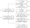
역 모델(H(f)-1)은 단계 60에서의 원격 응답의 함수로서 물리적 구동 신호(17)를 결정하기 위하여 필요하다. 본 기술 분야의 숙련된 자에 의하여 인식된 될 바와 같이, 역 모델은 직접적으로 계산될 수 있다. 또한 본 명세서 내에서 사용된 바와 같은 용어 "역(inverse)" 모델은 비정방 N×M 시스템을 위한 M×N "의사 역(pseudo inverse)" 모델을 포함한다. 더욱이, 예를 들어 스핀들 결합 차량 테스트 시스템 내에서의 "브레이크 온" 그리고 "브레이크 오프"를 갖는 영역과 같은 다른 포워드 모델(forward model; H)과 역 모델(H(f)-1)이 사용될 수 있다. 종래 기술의 이러한 점에 있어서, 이 방법은, 원하는 원격 트랜스듀서 응답(22)(이후 "원하는 응답"이라 함)을 이상적으로 복사하는 실제 응답(21)을 생성하는 구동 신호(17)를 획득하기 위해, 도 3b 및 도 4a에 도시된 반복 단계로 들어간다. 역 물리적 시스템 모델(H(f)-1)이 도면 부호 72에서 나타나는 반면에, 물리적 시스템(진동 시스템, 테스트 차량, 원격 트랜스듀서 및 계측기)은 도면 부호 10에서 나타난다. 도 3b를 참고하면, 단계 78에서, 초기 구동 신호(17; x1(t))를 결정하기 위하여 역 모델(72)이 목표 응답 보정(77)에 적용된다. 비록 목표 응답 보정이 매 흔하게 완화 이득 요소(relaxation gain factor; 95)에 의해 감소되더라도, 목표 응답 보정(77)은 초기 구동 신호를 위한 원하는 응답(22)일 수 있다. 역 모델(72)로부터의 계산된 구동 신호(17; x1(t))는 그후 단계 80에서 물리적 시스템(10)으로 인가된다. 인가된 구동 신호(17; x1(t))에 대한 물리적 시스템(10)의 실제 원격 트랜스듀서 응답(21; 이하 "실제 응답"이라 함) y1(t)는 그후 단계(86)에서 획득된다. 완전한 물리적 시스템(10)이 선형적(단위(unity)의 완화 이득(95)을 허용)이면, 그후 초기 구동 신호(17; x1(t))는 요청된 구동 신호로서 사용될 수 있다. 그러나, 물리적 시스템은 일반적으로 비선형적이기 때문에, 보정된 구동 신호(17)는 반복적인 과정에 의하여 도달되어야 한다(본 기술 분야의 지식을 가진 자에 의하여 이해하는 바와 같이, 유사한 물리적 시스템을 위한 이전 테스트에 사용된 구동 신호(17)는 초기 구동 신호로서 이용될 수 있다).The inverse model (H (f) -1 ) is needed to determine the
반복적인 프로세스는, 단계(88)에서 초기 구동 신호 (x1(t))에 기인한 제1 실제 응답(y1(t))을 기록하는 것, 제 1 실제 응답을 원하는 응답(22)과 비교하는 것, 그리고 단계 88에서 응답 오류(89; Δy1)를 차이로서 계산하는 것을 포함한다(제1 실제 응답 신호( y1(t))는 도 4a의 87에 제공됨). 단계(90)에서 응답 오류(89; Δy1)는 사전 선택된 임계값과 비교되고, 그리고 만약 응답 오류(89)가 임계값을 초과하면, 반복이 수행된다. 특히 응답 오류(89; Δy1)는 새로운 목표 응답 보정(77)을 제공하는 완화 이득 요소(95)에 의해 감소된다. 이 실시예에 있어서, 제2 구동 신호(17; x2(t))를 부여하기 위하여 제1구동 신호(17A; x1(t))에 추가되는 구동 신호 보정(94; Δx2)(단계(91)을 생성하기 위하여 역 전달 함수(H(f)-1)는 단계 92에서 새로운 목표 응답 보정(77)에 적용된다. 이 반복 과정(80 내지 92)은 응답 오류(89)가 모든 응답 채널 상의 사전 선택된 임계값 아래로 낮아질 때까지 반복된다. 원하는 응답(22)의 사전 결정된 임계값 내에 있는 응답(21)을 생성하는 최종 구동 신호(17)는 그후 시편 테스트를 수행하기 위하여 사용될 수 있다.The iterative process includes writing a first actual response y 1 (t) due to the initial driving signal x 1 (t) at
설명된 바와 같이, 응답 오류(89; Δy)는 통상적으로 완화 이득 요소(95; 또는 반복 이득)에 의하여 감소되어 목표 응답 보정(77)을 형성한다. 반복 이득(95)은 반복 과정을 안정화시키며 그리고 반복 오버슈트에 대한 수렴성비를 상충(trade off)한다. 더욱이, 반복 이득(95)은 물리적 시스템(10) 내에 존재하는 비선형성으로 인하여 반복 과정 동안 테스트 차량이 과부화(overloading)될 가능성을 최소화시킨다. 당업자가 이해하는 바와 같이, 반복 이득은 구동 신호 보정(94; Δx) 및/또는 응답 오류(89)에 적용될 수 있다. 도 4a에서 저장 장치(38)는 반복 과정 동안에 원하는 응답(22), 실제 응답(21) 그리고 이전 구동 신호(17a)를 저장하기 위해 사용될 수 있다. 물론, 메모리(34) 또한 사용될 수 있다. 또한, 점선(93)은 역 모델(72)이 물리적 시스템(10)의 반전의 평가임을 나타낸다. 위에서 설명된 바와 같이, 미네소타주 에덴 프라이리에 소재의 엠티에스 시스템즈 코포레이션의 RPCIIITM에 포함된 것과 같은 상업적으로 이용 가능한 소프트웨어 모듈을 사용하여 본 기술 분야의 지식을 가진 자가 도 4a의 블럭도를 실행할 수 있다.As described, the response error 89 (? Y) is typically reduced by the mitigation gain factor 95 (or iterative gain) to form the
이 시점에서, 구동 신호를 계산하기 위한 종래 기술의 변형된 방법이 또한 논의될 수 있다. 변형된 종래기술의 방법은 도 3a에 도시된 식별 단계 및 도 3b에 도시된 반복 위상의 다수의 단계를 포함한다. 편의상, 변형된 방법의 반복 단계는 도 3c 및 도 4b에 도시된 바와 같은 블록도에서 설명한다. 도 4b에 도시된 바와 같이, 목표 응답 보정(77)의 계산은 동일하다. 그러나, 실제 응답(21)과 원하는 응답(22) 사이의 응답 오류(89)가 선택된 임계값보다 크면, 현재의 반복을 위하여 새로운 목표 응답(79)을 얻기 위하여 단계 97에서 목표 응답 보정(77)이 이전 목표 응답(79A)에 더해진다. 역 모델(72)은 새로운 구동 신호(17)를 획득하기 위해 목표 응답(79)에 적용된다. 도 4b에 도시한 바와 같이, 위에서 설명된 이유를 위하여 반복 이득(95)이 사용될 수 있다.At this point, a modified method of the prior art for calculating the drive signal can also be discussed. The modified prior art method includes the identification step shown in FIG. 3A and the multiple phases of the repetitive phase shown in FIG. 3B. For convenience, the iterative steps of the modified method are illustrated in a block diagram as shown in Figures 3C and 4B. As shown in FIG. 4B, the calculation of the
도 4a 및 도 4b는 포괄적으로 조절기(100)를 포함하는 다른 형태의 반복 과정을 도시하며, 여기서 물리적 시스템 역 모델(72)을 개선하기 위하여 조절기는 반복 과정의 각 단계 동안에 작동한다. 이 과정은 미국특허 제7,031,949호에 상세하게 설명되어 있으며, 이 특허의 내용은 본 명세서 내에서 전체적으로 참고적으로 포함된다. 일반적으로, 도 4a에 도시된 바와 같이, 조절기(100)는 응답 오류(89)의 단순한 함수(simple function)(즉, 도 4b의 이전 목표 정보(79A) 없이)로서 목표 응답 보정(77)을 직접적으로 수신하는 역 모델(72)을 보정하며 그리고 여기서 물리적 시스템 구동 신호(17)는 이전의 구동 신호(17A)와 조합한 구동 신호 보정(94)을 포함한다. 반대로, 도 4b에 도시된 바와 같이, 역 모델(72)은 목표 응답 보정(77)과 이전의 목표 응답(79A)의 조합으로서 목표 응답(79)을 수신하며, 그리고 구동 신호(17)는 역 모델(72)을 적용함에 의하여 직접적으로 획득된다. 도 4b의 경우에 있어서, 조절기(100)는 도 4a와 개념적으로 동일한 형태로 역 모델(72)을 보정한다. 그러나, 도 4a 및 도 4b의 구성은 미국특허 제7,031,949호에 설명된 가상적 유사성 모델 과정에서 이용할 수 있는 다른 신호를 제공하며, 여기서 각 신호는 고유한 상황적 이점(inherent situational advantage)을 갖는다. 조절기(100)는 또한 반복적인 방법으로 동작할 수 있다.Figures 4A and 4B illustrate another type of iterative process that includes the
일반적으로, 본 발명의 태양이 도 5에 개략적으로 도시되며, 도 5는 도 1과유사하다; 그러나, 액추에이터(15)는 컴플라이언트 액추에이터 조립체(150)로 대체되었다. 테스트 시편에 의하여 보여지는 실제 부하를 시뮬레이션하는 테스트 시편상에 부하를 발생시키기 위하여 테스트 리그 내에 구현될 때, 컴플라이언트 액추에이터 조립체(150)는 이러한 시스템에서 공통적으로 보여지는 높은 주파수에서 큰 부하를 발생시킬 수 있어야 한다. 그러나, 컴플라이언트 액추에이터 조립체(150)는 낮은 강성 탄성 특성을 나타내어 테스트 시편(18)의 변위가 수용될 수 있다. 도 5의 개략적인 도면에서, 이러한 특성은 인식될 수 없다; 그러나, 각각이 도 7에 도시된 차량 스핀들 테스트 기구(200; 코스를 따라 주행하는 차량을 시뮬레이션하기 위하여 이는 차량 스핀들에 부하를 가한다)를 갖는 하나 이상의 차량 스핀들을 갖는 도로 시뮬레이터와 같은 다 자유도 내에서 부하를 가하기 위하여 테스트 시편 내에 적용될 때, 하나 이상의 자유도 내의, 그리고 특히 (차량의 시뮬레이션된 전방 움직임의 방향 및 이에 대한 측 방향 그리고 또한 캠버와 조향 모멘트 방향으로의) 수평 부하를 위한 이러한 컴플라이언스는 매우 유리한 것으로 알려져 있다. 차량을 테스트할 때 하나 이상의 수평 부하를 위한 부하 경로 내에 컴플라이언트 액추에이터 조립체를 제공하는 것은 테스트기가 동일한 기능을 갖지만 다른 특성을 갖는 차량 요소들, 예를 들어 다른 강성의 차축 또는 스태빌라이저 부싱을, 단계 54에서 특유의 테스트 데이터를 기록하지 않고 그리고 각각의 다른 부싱을 위하여 위에서 설명된 것과 같은 반복 과정을 이용하여 특유의 구동 신호를 발생시키지 않고 테스트하는 것을 허용할 수 있다.In general, an aspect of the present invention is schematically illustrated in Figure 5, wherein Figure 5 is similar to Figure 1; However, the
차량 스핀들에 연결된 테스트 시스템 형태로 도 7에 도시되었을지라도, 이는 하나의 예이다. 테스트 시스템에 인가되고 있는 하중에 기초한 다른 다자유도 액추에이터는, 제한되지는 않지만, 스티어링 기어 테스트 시스템, 스티어링 너클 테스트 시스템, 제어 아암 테스트 시스템 그리고 일반적으로 시편 또는 기구 움직임이 제어 채널 내로 그리고/또는 제어 채널 사이에 외란(disturbance)을 부여하는 어떠한 적용을 포함한다. Although shown in Figure 7 in the form of a test system connected to the vehicle spindle, this is an example. Other multi-degree-of-freedom actuators based on the load being applied to the test system include, but are not limited to, a steering gear test system, a steering knuckle test system, a control arm test system and, generally, And includes any application that imparts disturbance between channels.
컴플라이언트 액추에이터 조립체(150)의 제 1 실시예가 도 6에 개략적으로 도시된다. 피스톤(158)은 실린더 또는 보어(155) 내에서 슬라이딩 가능하다. 테스트 시스템 설계에 따라 단일 종단 또는 이중 종단 피스톤(158)과 보어(155)는 이중 작동 유압 액추에이터로서 작동한다. 한 쌍의 서보 컨트롤러(14)를 포함하는 흐름 제어 밸브(159)는 보어(155)에 유체적으로 연합되며 그리고 유압 유체를 보어(155)에 선택적으로 제공하여 피스톤(158)을 이동시킨다. 어큐뮬레이터(164)는 이중 작동 액추에이터의 각 챔버 또는 피스톤에 유체적으로 또는 기계적으로 연결된다. 다른 경우라면 어큐뮬레이터(164)는 강체 액추에이터에 탄성 영향(spring effect)을 도입한다. 각 어큐뮬레이터(164)는 압축성 유체(전형적으로 질소와 같은 가스, 기계적인 스프링 또는 다른 탄성 매체 또는 장치)의 제 1 부분(165)과 액체로 채워진 제 2 부분(167)을 포함하며, 이 액체는 가스와 비교하여 실질적으로 비압축성이다. 각 어큐뮬레이터(164)의 제 2 부분(167)은 보어(155)에 유체적으로 연결되거나 피스톤(158)에 기계적으로 연결된다. 공통적으로, 다이아프램(169; 또는 피스톤과 같은 동등한 분리 장치)이 각 어큐뮬레이터(164) 내에 제공되어 탄성 장치 또는 매체와 액체의 분리를 유지시킨다. 전형적으로 그러나 전적이지 않은, 질소 가스가 미리 채워진 유압 어큐뮬레이터(164) 또는 기계적 요소를 사용하는 것은 액추에이터 조립체(150)의 탄성 강성(즉, 컴플라이언스)의 조정을 허용하여 특정 테스트 시편의 요구 조건을 맞춘다.A first embodiment of a
원하는 성능을 얻기 위하여 액추에이터 조립체(150)의 다른 설계 고려 사항이 또한 이용될 수 있다. 예를 들어, 아직은 실질적으로 비활성화되는 저주파수에서 효과적이 되도록 또는 더 적은 컴플라이언스와 더 큰 강성을 보장하는 고주파수에서 적어도 실질적으로 더 강해지도록 컴플라이언스를 조정하기 위하여 어큐뮬레이터(164) 유효 면적과 피스톤(158)의 면적 간의 면적비, 어큐뮬레이터 피스톤의 질량 및/또는 어큐뮬레이터(164)로 들어가는/나가는 오일의 속도 중 어느 하나 또는 전부가 이용될 수 있다. Other design considerations of the
미국특허 제6,457,369호는 본 발명에서 이용될 수 있는 가스 스프링을 제공하기 위하여 압축성 가스의 체적을 이용한 다른 형태의 액추에이터(선형 또는 부분적으로 회전형)를 개시하며, 이는 전체적으로 본 명세서 내에 참고적으로 포함된다. 그러나, 미국특허 제6,457,369호에 설명된 컴플라이언트 액추에이터는 본 명세서에서 개시된 방식으로 사용되지 않는다. 미국특허 제6,457,369호에서, 컴플라이언트 액추에이터는 보다 높은 주파수 입력 외란에 또한 순응하는 높은 정적인 또는 낮은 주파수 부하를 제공하기 위하여 사용된다. 그러나, 필요하다면, 본 특허 내에서 설명된 바와 같은 유압 동력 공급(hydraulic powering up) 또는 동력 차단(shutting down)에 관한 일부 제어 기술이 포함될 수 있다. U.S. Patent No. 6,457,369 discloses another type of actuator (linear or partially rotatable) that utilizes the volume of compressible gas to provide a gas spring that may be used in the present invention, which is incorporated herein by reference in its entirety do. However, the compliant actuators described in U.S. Patent No. 6,457,369 are not used in the manner disclosed herein. In U.S. Patent No. 6,457,369, a compliant actuator is used to provide a high static or low frequency load that also complies with higher frequency input disturbances. However, if necessary, some control techniques relating to hydraulic powering up or shutting down as described in this patent may be included.
위에서 지시된 바와 같이, 컴플라이언트 액추에이터 조립체는 도 7에 도시된 테스트 시스템(200)과 같은 다자유도(다축성) 테스트 시스템에서 특히 유리하다. 테스트 시스템(200)이 미국특허 제6,640,638호에 상세하게 설명된다. 이 미국 특허는 본 명세서 내에 전체적으로 참고적으로 포함됨에도 불구하고 이는 도로 시뮬레이터의 한 형태이다. As indicated above, the compliant actuator assembly is particularly advantageous in a multi-degree of freedom (multi-axial) test system, such as the
도 7 그리고 그의 개략적인 묘사를 참고하면, 차량 스핀들 테스트 기구(200)는 도시되지 않은 차량의 스핀들에 선형력 그리고 회전 모멘트를 가하도록 설계된 시스템의 예이다. 차량 스핀들 테스트 기구(200)는 휠 아답터 하우징(216)을 포함하며, 이 하우징은 일반적인 방식으로 차량 스핀들에 고정된다. 제 1 로딩 조립체(213; loading assembly)는 휠 아답터 하우징(216) 그리고 수직으로 연장된 한 쌍의 로딩 링크 또는 스트러트(220)를 포함한다. 전체적으로, 제 1 로딩 조립체(213)는 액추에이터 조립체(223 및 225) 각각으로 하나의 차축을 따르는 방향으로 또는 2개의 상호 직교적인 축(222 및 224)을 따르는 방향으로 스핀들에 부하를 가한다. 또한 제 1 로딩 조립체(213)는 액추에이터(227)로 축(222 및 224)에 상호 직교적인 축(226) 주위에 모멘트 또는 토크를 가할 수 있다. Referring to FIG. 7 and a schematic depiction thereof, the vehicle
예시적인 실시예에서, 테스트 기구(200)는 또한 제 2 로딩 조립체(215)를 포함한다. 제 2 로딩 조립체(215)는 다수의 스트러트(217) 그리고 액추에이터 조립체(219A, 219B 및 229) 중 적어도 하나를 포함한다. 대체로, 제 2 로딩 조립체(215)는 액추에이터 조립체(229)를 이용하여 실질적으로 축(226)을 따라 힘을 가할 수 있을 뿐만 아니라 액추에이터 조립체(219A 및 219B)를 이용하여 축(224)에 모멘트를 가할 수 있으며 그리고 액추에이터 조립체(219A, 219B 및 229)를 이용하여 축(222)에 평행한 축 주위에 모멘트를 가할 수 있다. In an exemplary embodiment, the
각 액추에이터 조립체가 관련된 액추에이터에 직렬로 결합된, 유압 또는 전기식일 수 있는 탄성 요소(240; spring element)를 포함하고 있다는 점에서 도 7의 액추에이터 각각은 컴플라이언트 액추에이터 조립체의 제 2 형태를 포함한다. 탄성 요소는 기계적인 스프링(예를 들어, 코일 스프링) 또는 가스 또는 공기 스프링을 포함할 수 있다. 2개의 스트러드에 직렬로 연결된 탄성 요소로서 도 7에 도시되었을지라도, 이 탄성 요소가 액추에이터로부터, 제한되지는 않지만 부하 경로 내의 어떠한 레버 아암의 부분 내에 포함되는 것과 같은 시편에 대한 결합부로의, 또는 레버 아암의 컴플라이언트 선회를 제공하기 위하여 레버 아암의 부분까지의 부하 경로를 따라 어디에도 또는 부하 경로 내의 어떤 결합부 내에 포함될 수 있다는 것이 이해되어야 한다. 공통적으로, 탄성 요소는 축방향 탄성 효과를 제공할 것이며, 이 탄성 요소는 레버 아암에 작동적으로 연결되어 도시된 바와 같이 컴플라이언를 갖고 레버 아암의 선회점뿐만 아니라 축방향 탄성 요소(240)가 이동하는 것을 허용한다. 바꾸어 말해, 본 발명의 한 태양은 테스트 시스템의 강성이 실질적으로 는 테스트 시편의 강성보다 실질적으로 작도록 컴플라이언트 액추에이터 조립체를 제공한다. Each of the actuators in FIG. 7 includes a second form of compliant actuator assembly in that it includes a spring element, which may be hydraulic or electric, in which each actuator assembly is coupled in series with an associated actuator. The resilient element may comprise a mechanical spring (e. G., A coil spring) or a gas or air spring. Although shown in Fig. 7 as an elastic element connected in series to two struts, this elastic element may be connected to the coupling to the specimen, such as, but not limited to, being contained within the portion of any lever arm in the load path, or But may be included anywhere along the load path to the portion of the lever arm to provide a compliant turn of the lever arm, or in any engagement within the load path. Commonly, the resilient element will provide an axial elastic effect, which is operatively connected to the lever arm, such that the pivot point of the lever arm as well as the axial
기계적인 스프링(240)과 비교해볼 때, 액추에이터 조립체의 컴플라이언스가 제어 루프(도 5에서의 신호 라인(19 및 15A)) "안에" 있기 때문에 이중 작동 액추에이터 종단들 사이에서 작동적으로 결합된 컴플라이언스 요소 또는 고정된 그리고 단일 작용 액추에이터 종단을 갖는 컴플라이언트 액추에이터(150)가 유리할 수 있으며, 그로 인하여 결과적인 움직임의 폐루프 제어를 제공하며, 이는 제어되지 않은 공진 응답을 감소 또는 제거할 수 있다는 것이 주목되어야 한다. Compared to the
테스트 시스템 내에 컴플라이언트 액추에이터 또는 조립체를 포함시키는 것의 특별한 이점은 다수의 "유사하지만 다른" 테스트 시편을 테스트하기 위하여 새로운 구동 신호가 필요하지 않을 수 있다는 것이다. 때때로, 선행 기술의 테스트 시스템에서, 테스트될, 유사하지만 다른 테스트 시편 각각을 위한 위에서 설명된 것과 같은 반복 과정을 이용한 새로운 구동 신호는 도 3a의 단계 54에서 수집되고 그리고 기록된 각 대응 테스트 시편의 고유의 응답 신호에 기초한다. 그러나, 유사하지만 다른 테스트 시편을 단계 52에서 차량과 같은 그 작동 환경 내에 설치하고 그리고 데이터를 기록하는 것은 노동력과 시간 면에서 매우 비용이 많이 소요된다. 동일하게, 고유의 기록된 데이터에 기초한 반복 과정을 이용하여 구동 신호를 생성하는 것 또한 전형적으로 시간이 매우 소요되며 그리고 반복 과정의 특성으로 인하여 테스트 시편 및 /또는 테스트 시스템 상에서의 마모를 야기한다. 하나 이상의 컴플라이언트 액추에이터 조립체의 사용이 시스템 민감도, 특히 시편 유발 움직임에 대한 민감도를 줄일 수 있으며 따라서 제어 루프 외란 제거 능력을 증가시키고 그리고 다수의 유사한 그러나 다른 테스트 시편을 위하여 동일한 구동 신호가 사용되는 것을 허용한다는 점이 알려져 있다. A particular advantage of including a compliant actuator or assembly within a test system is that a new drive signal may not be needed to test a number of "similar but different" test specimens. Sometimes, in a prior art test system, a new drive signal using an iterative process as described above for each of the similar but different test specimens to be tested is collected in
컴플라이언트 액추에이터 조립체는 또한 테스트 동안에 때때로 다른 특징을 나타내는 테스트 시편에게 테스트를 수행하는데 도움을 준다. 컴플라이언트 부하 조립체는 또한 시간이 지남에 따라 가해진 힘 또는 부하를 더욱 일관적으로 유지할 수 있다. The compliant actuator assembly also helps to perform tests on test specimens that sometimes exhibit other features during testing. The compliant load assembly can also maintain the applied force or load more consistently over time.
테스트 시스템 내에서의 컴플라이언트 액추에이터 조립체의 사용으로 달성된 다른 중요한 이점이 이러한 컴플라이언트 액추에이터 조립체를 갖지 않은 테스트 시스템과 비교할 때 위에서 설명된 것과 같은 반복 과정을 이용하여 구동 신호를 얻는데 필요한 반복의 전체 회수가 상당히 감소된다는 것임이 주목되어야 한다. 일반적으로, 위에서 설명된 이유로, 반복 이득 또는 완화 이득 계수(95)는 작게, 예를 들어 대략 0.3으로 유지되어야 하며 오버슈트는 일어나지 않으며 그리고 테스트 시편을 손상시키지 않도록 따라서 한다. 완화 이득 계수가 작기 때문에 최종 구동 신호를 얻는데 요구되는 반복 횟수는 상당히 크다. 예를 들어 30 반복이다. 각 반복이 도로 시뮬레이터와 같은 테스트 시스템을 위하여 각 반복이 1시간 이상 걸리는 것이 흔하지 않은 것은 아니다; 이러한 이유로 최종 구동 신호를 집중시키는 것은 쉽게 30시간 이상이 걸릴 수 있다. 그러나, 테스트 시스템이 테스트 시편보다 실질적으로 덜 단단해지는 것을 사실상 허용하는 컴플라이언트 액추에이터 조립체의 사용은 (완성 차량 스핀들 결합 도로 시뮬레이터를 갖는 수평 채널, 또는 예를 들어 차량의 뒤 차축/서스펜션 또는 한 코너의 차량 서스펜션을 테스트하기 위하여 하나 이상의 스핀들 결합 로드 시뮬레이터를 이용하는 부분적인 차량 테스트 또는 하나 이상의 컴플라이언트 액추에이터 조립체에 연결된 엔진 마운트와 같은 직접적으로 결합된 요소 테스트 시편과 마찬가지로, 적어도 일부 자유도에서) 약 0.5보다 큰 완화 이득 계수가 사용되는 것을 허용하며, 그리고 다른 실시예에서는 약 0.65보다 큰 완화 이득 계수가 사용되는 것을 허용하며, 그리고 또 다른 실시예에서는 약 70.5보다 큰 완화 이득 계수가 사용되는 것을 허용하며, 그리고 다른 실시예에서는 0.8보다 큰 완화 이득 계수가 사용되는 것을 허용한다. 더 큰 완화 이득 계수의 사용은 최종 구동 신호를 집중시키는데 요구되는 반복의 횟수를 과감하게 줄이며, 그로 인하여 상당한 시간 및 비용을 절약한다. 여기서 완화 이득 계수가 증가함에 따라 필요한 반복의 횟수는 일반적으로 줄어든다; 따라서, 반복 횟수가 감소되기 때문에 완화 이득 계수의 어떠한 증가는 현저한 이점을 제공할 수 있다. Another important advantage achieved with the use of compliant actuator assemblies within a test system is that the total number of iterations required to obtain the drive signal using the iterative process as described above, when compared to a test system without such a compliant actuator assembly Is significantly reduced. Generally, for the reasons described above, the repetition gain or
이 시점에서, 위에서 언급된 이점이 새로운 구동 신호에 도달하기 위하여 처리 또는 계산 중에 사용된 어떠한 형태의 모델을 위하여 얻어진다는 점 또한 주목되어야 한다. 이는 테스트 시스템 내에서의 하나 이상의 컴플라이언트 액추에이터 조립체의 사용으로 달성된 반복 횟수 감소이기 때문에 사용된 모델의 형태는 중요하지 않다. 따라서 본 발명은 예를 들어 선형 모델 그리고 비선형 모델과 함께 사용될 수 있기 보다는, 구동 신호의 반복 동안에 사용된 예시적인 테스트 시스템 방법론에 제한되지 않는다. It should also be noted that at this point, the advantages mentioned above are obtained for any type of model used during processing or calculation to arrive at a new drive signal. The type of model used is not important because it is a reduction in the number of iterations achieved with the use of one or more compliant actuator assemblies within the test system. Thus, the present invention is not limited to the exemplary test system methodology used during repetition of drive signals, rather than being usable with, for example, linear models and non-linear models.
선행 기술의 시스템 및 방법과 컴플라이언트 액추에이터 조립체를 갖는 본 발명의 테스트 시스템 및 방법 간의 다른 차이는 예를 들어 (적어도 일부 자유도에서) 테스트 시편의 강성의 10%와 같이 테스트 시편보다 훨씬 부드럽도록 테스트 시스템을 조정함에 의하여 테스트 시편에 대하여 선택된 컴플라이언스 또는 선택된 강성을 갖도록 테스트 시스템(물리적 테스트 리그)의 컴플라이언스를 조절할 수 있다는 것이다. 이는 다시 더 큰 완화 이득 계수가 사용되는 것을 허용하며, 그로 인하여 반복 횟수를 줄인다. 테스트 시편의 강성 또는 컴플라이언스에 대한 이러한 조정은 완화 이득 계수가 유사한 테스트 시편과는 관계없게 되는 것을 허용할 수 있으며, 예를 들어 도로 시뮬레이터가 한 테스트에서 차의 강도의 10% 그리고 다른 테스트에서 트럭의 강도의 10%를 갖도록 조정되었다면, 각 차량을 위하여 동일한 반복 횟수 또는 거의 동일한 반복 횟수가 필요할 수 있다. Another difference between the prior art systems and methods and the test system and method of the present invention with compliant actuator assemblies is that the test system < RTI ID = 0.0 > (e. G., At least some degrees of freedom) To adjust the compliance of the test system (physical test rig) to have the selected compliance or selected stiffness for the test specimen. This again allows a larger relaxation gain factor to be used, thereby reducing the number of iterations. This adjustment to the stiffness or compliance of the test specimen may allow the relaxation gain factor to be independent of similar test specimens, for example, if the road simulator is used for 10% of the strength of the car in one test, If adjusted to have 10% of the strength, the same number of repetitions or almost the same number of repetitions may be required for each vehicle.
본 발명의 태양으로부터 이득을 얻을 수 있는 다른 예시적인 반복 과정 및 실시예가 미국특허 제8,135,556호; 미국특허공개 제2013/030444A1; 및 본 출원의 우선권 출원과 동일한 일자에 출원된, 발명의 명칭이 "연결된 하이브리드 동적 시스템을 테스트하는 방법 및 시스템"인 미국특허출원에 개시되어 있으며, 이 선행 문헌들은 전체적으로 참고로 포함된다. Other exemplary iterations and embodiments that may benefit from aspects of the present invention are described in U.S. Patent Nos. 8,135,556; U.S. Patent Publication No. 2013 / 030444A1; And U.S. Patent Application, entitled " Method and System for Testing a Linked Hybrid Dynamic System, " filed on the same day as the priority application of the present application, the entire contents of which are incorporated by reference in their entirety.
일반적으로, 위에서 언급된 특허 및 출원은 연결된 하이브리드 동적 시스템의 시뮬레이션을 제어하기 위한 장치를 제공한다. 한 예시적인 장치에서, 장치는 시스템의 물리적 구성 요소를 구동하도록 그리고 테스트 리그에 구동 신호 입력을 가하는 결과로서 테스트 리그 응답을 발생시키도록 구성된 물리적 테스트 리그를 포함한다. 프로세서는 물리적 요소에 대한 상호 보완적인 시스템의 가상 모델(본 명세서에서 또한 "가상 모델"이라 칭함)과 함께 구성된다(즉, 상호 보완적인 시스템의 가상 모델과 물리적 요소는 완전한 하이브리드 동적 시스템을 포함한다). 프로세서는 입력으로서 테스트 리그 응답의 제 1 부분을 수신하며 그리고 수신된 테스트 리그 응답의 제 1 부분과 가상 구동 신호를 입력으로 이용하여 상호 보완적인 시스템의 모델 응답을 발생시킨다. 프로세서는 또한 차이를 형성하기 위하여 테스트 리그 응답의 다른 제 2 부분을 상호 보완적인 시스템의 가상 모델로부터의 대응하는 응답과 비교하도록 구성되며, 여기서 이 차이는 테스트 구동 신호를 발생시키기 위하여 사용될 시스템 동적 응답을 형성하기 위하여 사용된다. Generally, the above-mentioned patents and applications provide an apparatus for controlling the simulation of a connected hybrid dynamic system. In one exemplary apparatus, the apparatus includes a physical test rig configured to drive a physical component of the system and to generate a test rig response as a result of applying a drive signal input to the test rig. A processor is configured with a virtual model of a complementary system to a physical element (also referred to herein as a "virtual model") (i.e., the virtual model and physical elements of the complementary system include a complete hybrid dynamic system ). The processor receives the first portion of the test rig response as input and generates a model response of the complementary system using the first portion of the received test rig response and the virtual drive signal as input. The processor is also configured to compare the other second portion of the test rig response to a corresponding response from a virtual model of the complementary system to form a difference wherein the difference is a system dynamic response to be used to generate the test drive signal Lt; / RTI >
실시예에서, 프로세서는 또한 테스트 구동 신호를 발생시키도록, 테스트 리그 응답을 수신하도록 그리고 상호 보완적인 시스템의 가상 모델로부터의 응답을 발생시키도록 구성되며, 또한 프로세서는 테스트 리그 응답을 상호 보완적인 시스템의 가상 모델로부터의 응답과 비교하여 하이브리드 시뮬레이션 과정 오류를 발생시킨다. 상호 보완적인 시스템의 가상 모델로부터의 응답과 테스트 리그 응답 간의 차이가 규정된 임계점 이하일 때까지 오류는 역 시스템 동적 응답 모델을 이용하여 반복적인 방식으로 감소된다. In an embodiment, the processor is also configured to receive a test rig response to generate a test drive signal, and to generate a response from a virtual model of the complementary system, To generate a hybrid simulation process error. Errors are reduced in an iterative manner using the inverse system dynamic response model until the difference between the response from the virtual model of the complementary system and the test rig response is below a prescribed threshold.
도 8은 결합된 하이브리드 동적 시스템(hybrid dynamic system)을 위한 시뮬레이션을 제어하는 예시적인 장치를 도시하며, 여기서 본 발명의 태양은 본 명세서에서 설명된 예시적인 장치에 제한되는 것이 아니라 위에서 확인된 특허 및 특허출원 내의 어떠한 다른 장치에도 적용될 수 있다는 것이 이해되어야 한다. FIG. 8 illustrates an exemplary apparatus for controlling simulation for a combined hybrid dynamic system, wherein aspects of the present invention are not limited to the exemplary apparatus described herein, but rather, It is to be understood that the invention may be applied to any other device within the patent application.
예시적인 장치에서, 상호 보완적인 차량 모델(370)은 컴퓨터의 하드 디스크와 같은 적절한 비일시적 컴퓨터 독출 가능한 매체 내에 제공되며 그리고 프로세서에 의하여 접근 가능하다. 그러나, 본 발명으로부터 벗어남이 없이 다른 시스템이 모델화될 수 있음에 따라 차량의 모델은 단지 예시적인 것이다. 또한 설명의 목적을 위하여 물리적 요소는 차량 서스펜션 시스템에 채용된 스트러트이다. 완성 차량의 테스트에 제한되지는 않지만 위에서 확인된 특허출원 내에 설명된 바와 같은 덜 실제적인 타이어와 휠을 포함하는 스트러트가 단지 물리적 요소의 예임에 따라 다른 요소가 테스트될 수 있다. 구동 신호(들)을 받아들이고 그리고 테스트 리그(372)의 부분인, 위에서 설명된 컴플라이언트 액추에이터 조립체들 중 어떠한 것에 응답(들)을 제공하는 테스트 리그(372)가 또한 제공된다. 이 예에서, 테스트 리그(372)는 테스트 리그(372) 내에 장착된 물리적 스트러트를 테스트하도록 구성된다. 그러나, 테스트 리그(372)는 다른 구조적 요소를 테스트하기 위하여 구성될 수 있다. 테스트 리그(372)는 리그 컨트롤러(374)를 갖는다.In the exemplary apparatus, the
장치는 테스트 리그(372)를 구동하기 위하여 사용된 구동 신호를 발생시키기 위하여 사용될 수 있는 시스템 동적 응답 모델을 형성 또는 확인하다. 한 예로서, 시스템 동적 응답 모델(376)은 주파수 응답 함수(FRF)일 수 있다. 상호 보완적인 시스템의 모델(370)을 운영하는 동일한 프로세서에 의하여 시스템 동적 응답 모델(376)이 또한 결정되거나 계산될 수 있다. 그러나, 개별 프로세서에서 시스템 동적 모델(376)이 또한 결정되거나 계산될 수 있다. The apparatus forms or identifies a system dynamic response model that can be used to generate the drive signals used to drive the
도 8은 시스템 동적 응답 모델(376)을 형성하기 위한 장치 및 단계를 도시한다. 이는 시스템 응답 모델링 단계라 할 수 있다. 이 시스템 동적 응답 모델(376)은 이후에 설명될 도 9의 반복 과정에서 사용될 수 있다. 도 8에서, 랜덤 테스트 구동 신호(378)는 설치된 (스트러트와 같은) 차량 요소(380)를 갖는 테스트 리그(372)의 의도대로 실행된다. 랜덤 테스트 리그 구동 신호(378)는 램덤 진폭, 광대역 주파수 구동 신호와 같은 포괄적인 구동 신호일 수 있다. 장치가 2개의 응답에 제한되지는 않지만, 개시된 실시예에서 2개의 응답이 측정된다. 랜덤 테스트 리그 힘 신호(382)와 같은, 이 응답들 중 하나는 상호 보완적인 시스템의 차량 모델(370)에 인가될 것이다. 랜덤 리그 변위(384)와 같은 다른 응답은 상호 보완적인 시스템의 가상 모델(370)의 응답과 비교될 응답이다. 도 8의 개시된 실시예에서, 제 1 응답(382)은 테스트 리그(372) 상에서 스트러트에 의하여 가해진 힘인 반면에, 제 2 응답(384)은 스트러트(380)의 변위이며, 이는 또한 리그 컨트롤러(374)에 대한 입력으로서 제공될 수 있다. 다른 응답 신호가 테스트 리그(372)로부터 제공될 수 있음에 따라 힘과 변위 신호가 단지 예시적인 것임이 주목될 것이다. FIG. 8 shows an apparatus and steps for forming a system
테스트 리그(372)로부터의, 랜덤 리그 힘(382)과 같은 응답은 랜덤 모델 구동신호(386)를 형성하기 위하여 상호 보완적인 시스템의 가상 차량 모델(70)로 공급된다. 상호 보완적인 시스템의 가상 차량 모델(370)은 스트러트(380)의 경우에 테스트 하의 요소를 배제한다. 변위인 경우에, 상호 보완적인 시스템의 가상 차량 모델(370)은 랜덤 모델 응답 신호(388)로 랜덤 모델 구동 입력 신호(386)에 응답한다. A response, such as a
과정의 제 3 단계에서, 상호 보완적인 시스템의 가상 차량 모델(370)의 랜덤 응답(388)은 관련된 테스트 리그 랜덤 응답(384)과 비교된다. 랜던 응답 차이(392; 여기서는 예를 들어, 변위)를 형성하기 위하여 비교(390)가 수행된다. 랜덤 응답 차이(392)와 랜덤 리그 구동 신호(378) 간의 관계는 시스템 동적 응답 모델(376)을 수립한다. 도 2의 반복적인 시뮬레이션 제어 과정에서의 테스트 리그 구동 신호 예측을 위하여 시스템 동적 응답 모델(376)은 역전되고 그리고 사용될 것이다. In a third step of the process, the
시스템 동적 응답 모델(376)의 결정이 오프라인 과정에서 이루어질 수 있어 고전력 그리고 고속의 연산 능력이 요구되지 않는다. 더욱이, 데이터를 획득할 필요가 없기 때문에 가상 모델 내에서 또는 물리적 환경에서 이 요소가 어떻게 응답할 것인지에 대한 이전의 지식없이 어떠한 요소가 테스트될 수 없다. 요소(380)가 물리적 시스템 내에 있을 때 시스템 동적 응답 모델(376)의 오프라인 측정은 상호 보완적인 시스템의 가상 모델의 응답(88)과 리그 입력부에 대한 리그 응답(384)에 있어서의 차이의 감도를 측정한다. 도 2에서 보여지는 바와 같이, 리그 구동 신호(378)와 시스템 응답 차이(392) 간의 관계가 모델화되면, 오프라인 반복 과정이 수행된다. 이는 테스트 구동 신호 발전 단계로 고려될 수 있다. The determination of the system
오프라인 반복인 도 2의 반복적인 과정에서, 테스트 요소(380)를 배제한 상호 보완적인 시스템의 가상 모델(370)이 작동한다. 예시적인 실시예에서, 가상 모델(370)은 가상 차량의 상호 보완적인 시스템이며, 그리고 배제된 테스트 요소는 스트러트(380)이다. 상호 보완적인 시스템의 가상 모델(370)의 응답(400)을 발생시키기 위하여 가상 차량은 테스트 도로 상에서 주행한다. 예로써, 스트러트(380)가 실제로 존재하지 않기 때문에 이는 실제로 응답(400)에 의하여 측정된 스트러트(380)에 의하여 점유될 공간의 변위임에도 불구하고, 응답(400)은 스트러트(380)의 변위를 나타낼 수 있다. 가상 테스트 도로 입력에 더하여, 상호 보완적인 시스템의 가상 모델(370)로의 부가적 입력이 도면 부호 398로서 도시된다. 상호 보완적인 시스템의 차량 모델(370)로의 부가적 모델 입력(398)은 테스트 리그(372)로부터의 테스트 리그 응답(394)에 기초한다. 테스트 리그(372)에서 측정된 힘과 같은 부가적인 모델 입력(398)은 테스트 동안에 차량 모델(370)에 동시에 인가된다. 초기 반복(N=0)을 위하여, 상호 보완적인 시스템의 가상 모델(370)로의 입력(398)은 전형적으로 0에 있을 것이다. In the iterative process of FIG. 2, which is an offline iteration, a complementary system
상호 보완적인 시스템의 가상 모델(370)의 응답(400)은 테스트 리그(372)로부터의 테스트 리그 응답(396)과 비교된다. 상호 보완적인 시스템의 가상 모델(370)의 응답(400)이 변위라면, 이 테스트 리그 응답(396) 또한 변위일 수 있다. 402에서의 비교가 테스트 리그 응답(396)과 상호 보완적인 시스템의 가상 모델(370)의 응답(400) 사이에서 이루어져 응답 차이(403)를 형성한다. The
응답 차이(403), 이 경우 변위 차이가 원하는 차이(404)와 비교된다. 전형적으로, 반복적인 제어 과정을 위하여 원하는 차이(404)는 0(zero)으로 설정될 것이다. 그러나, 또 다른 실시예에서, 본 발명의 범위를 벗어남이 없이 다른 원하는 차이가 이용될 수 있다. The
응답 차이(403)와 원하는 차이(404) 간의 비교(406)는 도 1에 도시된 단계에서 이전에 결정된 시스템 동적 반응 모델(376)의 역수(inverse; FRF- 1)에 의하여 사용된 시뮬레이션 오류(407)를 생성한다. 시스템 동적 반응 모델(376)의 역수는 도 2에서 도면 부호 408로 나타난다. 구동 신호 보정(409)이 412에서 이전 테스트 리그 구동 신호(410)에 추가되어 다음 테스트 리그 구동 신호(414)를 발생시킨다. 전형적으로, 시뮬레이션 오류(407)는 완화 이득 계수(relaxation gain factor)에 의하여 감소한다. 완화 이득 계수(또는 반복 이득)는 반복적인 과정을 안정화시키며 그리고 반복 오버슈트(iteration shoot)에 대한 수렴성비(rate of convergence)를 상충(trade off)한다. 또한, 반복 이득은 물리적 시스템 내에 존재하는 비선형성에 기인한 반복 과정 동안에 테스트 요소가 과부하될 가능성을 최소화시킨다. 당업자에 의하여 인식될 바와 같이, 필요하다면 반복 이득은 구동 신호 보정(409)에 적용될 수 있다.The
다음 테스트 리그 구동 신호(414)는 테스트 리그(372)에 인가되며 그리고 제1 및 제 2 응답이 측정된다. 차량 모델(370)에 인가될 응답(394)은 테스트 리그 응답(306)과 비교된 응답(400)을 상호 보완적인 시스템의 프로세서와 가상 모델(370)을 통하여 발생시킨다. 결과적인 시뮬레이션 오류(407)가 원하는 허용치까지 감소될 때까지 과정은 되풀이하여 반복(화살표 397과 399로 표현됨)된다. The next test
차량 모델(370)의 처리와 최종 테스트 리그 구동 신호(414)의 결정은 단일 프로세서 내에서 수행될 수 있다. 그러나, 어떤 실시예에서는, 다중 프로세서가 이용될 수 있다. 또한, 시뮬레이션 오류를 결정하는 과정과 테스트 리그 구동 신호(414)의 결정은 오프라인 상에서 수행될 수 있다. The processing of the
대상물이 구조적인 특징 및/또는 방법론적인 작용 특유의 언어로 설명되었을지라도, 법원에 의하여 간주된 바와 같이 첨부된 특허청구범위에서 한정된 대상물이 위에서 설명된 특정 특징 또는 작용을 반드시 제한하는 것이 아니라는 점이 이해된다. 더 정확하게 말하면, 위에서 설명된 특정 특징 및 작용은 특허청구범위를 실행하는 예의 형태로서 개시된다. It is to be understood that, although the subject matter has been described in language specific to structural features and / or methodological acts, it is to be understood that the subject matter defined in the appended claims is not necessarily to limit the particular features or acts described above, do. Rather, the specific features and acts described above are disclosed as example forms of implementing the claims.
Claims (21)
비일시적 컴퓨터 저장 장치;
비일시적 저장 장치와 작동 가능하며 그리고 하기 단계를 실행할 때 비일시적 컴퓨터 저장 장치 상에 저장된 명령을 실행하도록 구성된 프로세서를 포함하는 테스트 시스템.
(a) 물리적 테스트 리그에 구동 신호를 인가;
(b) 테스트 구동 신호에 대한 물리적 테스트 리그와 테스트 시편의 실제 응답 신호를 획득;
(c) 실제 응답 신호와 선택된 응답 신호의 함수로서의 오류 계산;
오류가 선택된 임계값을 초과하면,
(d) 오류와 완화 이득 계수에 기초하여 새로운 구동 신호 획득; 및
(e) 단계(a) 내지 (d)를 반복하며, 여기서 오류가 선택된 임계값에 도달할 때까지 새로운 구동 신호는 새로운 구동 신호임. A physical test rig having a compliant actuator assembly responsive to a drive signal and a test specimen automatically coupled to the compliant actuator assembly;
Non-volatile computer storage;
A processor configured to execute instructions stored on non-volatile computer storage devices, the computer system being operable with non-volatile storage and executing instructions stored on non-volatile computer storage devices when executing the following steps.
(a) applying a drive signal to a physical test rig;
(b) Acquiring the actual response signal of the physical test rig and the test specimen for the test drive signal;
(c) error calculation as a function of the actual response signal and the selected response signal;
If the error exceeds the selected threshold,
(d) acquiring a new drive signal based on the error and the relaxation gain factor; And
(e) repeating steps (a) through (d), wherein the new drive signal is a new drive signal until the error reaches a selected threshold value.
(a) 물리적 테스트 리그에 구동 신호를 가하고:
(b) 테스트 구동 신호에 대한 테스트 시스템의 실제 응답 신호를 획득하고;
(c) 프로세서로 실제 응답 신호 및 선택된 응답 신호의 함수로서 오류를 계산하고;
오류가 선택된 임계값에 도달하지 않으면;
(d) 오류와 완화 이득 계수에 기초하여 새로운 구동 신호를 획득하고; 그리고
(e) 단계 (a) 내지 (d)를 반복하되, 여기서 오류가 선택된 임계값에 도달할 때까지 테스트 구동 신호는 새로운 구동신호인 방법. A method of controlling a test system comprising a physical test rig with compliance for a load applied to a test specimen and responsive to a drive signal to generate a selected response signal,
(a) applying a drive signal to a physical test rig:
(b) obtaining an actual response signal of the test system for the test drive signal;
(c) calculating an error as a function of the actual response signal and the selected response signal to the processor;
If the error does not reach the selected threshold;
(d) obtaining a new drive signal based on the error and the relaxation gain factor; And
(e) repeating steps (a) through (d), wherein the test drive signal is a new drive signal until the error reaches a selected threshold.
(f) 선택된 임계값에 도달한 오류에 대응하는 새로운 구동 신호를 테스트 시스템에 인가하여 테스트 시편에 대한 테스트를 수행하고,
(g) 테스트 시스템 내의 테스트 시편을 테스트 시편과는 유사하지만 다른 새로운 테스트 시편으로 교체하며; 그리고
(h) 선택된 임계값에 도달한 오류에 대응하는 새로운 구동 신호를 새로운 테스트 시스템에 인가하여 새로운 테스트 시편에 대한 테스트를 수행하는 것을 더 포함하는 방법.
21. The method according to any one of claims 15 to 20, wherein after step (e)
(f) applying a new driving signal corresponding to the error that has reached the selected threshold value to the test system to test the test specimen,
(g) replacing test specimens in test systems with new test specimens similar to test specimens; And
(h) applying a new drive signal corresponding to an error that has reached the selected threshold to a new test system to perform a test on a new test specimen.
Applications Claiming Priority (3)
| Application Number | Priority Date | Filing Date | Title |
|---|---|---|---|
| US201361875645P | 2013-09-09 | 2013-09-09 | |
| US61/875,645 | 2013-09-09 | ||
| PCT/US2014/054803 WO2015035394A1 (en) | 2013-09-09 | 2014-09-09 | Test system having a compliant actuator assembly and iteratively obtained drive |
Publications (1)
| Publication Number | Publication Date |
|---|---|
| KR20160053983A true KR20160053983A (en) | 2016-05-13 |
Family
ID=51582536
Family Applications (1)
| Application Number | Title | Priority Date | Filing Date |
|---|---|---|---|
| KR1020167009132A KR20160053983A (en) | 2013-09-09 | 2014-09-09 | Test system having a compliant actuator assembly and iteratively obtained drive |
Country Status (6)
| Country | Link |
|---|---|
| US (1) | US20150073601A1 (en) |
| EP (1) | EP3044564A1 (en) |
| JP (1) | JP2016529528A (en) |
| KR (1) | KR20160053983A (en) |
| CN (1) | CN105705927A (en) |
| WO (1) | WO2015035394A1 (en) |
Families Citing this family (3)
| Publication number | Priority date | Publication date | Assignee | Title |
|---|---|---|---|---|
| US10184864B2 (en) * | 2015-12-10 | 2019-01-22 | Mechanical Testing Services, Llc | Intelligent automated load control system and method |
| JP2019526045A (en) * | 2016-06-29 | 2019-09-12 | イリノイ トゥール ワークス インコーポレイティド | Inspection system with real-time compensation of changing system parameters |
| CN109635389B (en) * | 2018-11-29 | 2022-12-20 | 中国航空工业集团公司沈阳飞机设计研究所 | Rigidity test data processing method for electric steering engine |
Family Cites Families (35)
| Publication number | Priority date | Publication date | Assignee | Title |
|---|---|---|---|---|
| US4658656A (en) * | 1985-08-28 | 1987-04-21 | Mts Systems Corporation | Multiple axis test machine reproducing road excited vehicle vibration |
| JP2681772B2 (en) * | 1985-11-07 | 1997-11-26 | 株式会社豊田中央研究所 | Vibration control device |
| JPS63235110A (en) * | 1987-03-24 | 1988-09-30 | Toyota Motor Corp | Front suspension for vehicle |
| US5598076A (en) * | 1991-12-09 | 1997-01-28 | Siemens Aktiengesellschaft | Process for optimizing control parameters for a system having an actual behavior depending on the control parameters |
| US5430645A (en) * | 1993-09-07 | 1995-07-04 | Keller; A. Scott | Robotic system for testing of electric vehicles |
| GB9319788D0 (en) * | 1993-09-24 | 1993-11-10 | Instron Ltd | Structure testing machine |
| US5650704A (en) * | 1995-06-29 | 1997-07-22 | Massachusetts Institute Of Technology | Elastic actuator for precise force control |
| WO1997011344A1 (en) * | 1995-09-18 | 1997-03-27 | Hitachi, Ltd. | Vibrating table system and control method therefor |
| JPH1011103A (en) * | 1996-06-27 | 1998-01-16 | Toyota Motor Corp | Control device for actuator and method for calculating feedback gain |
| JPH10185788A (en) * | 1996-12-27 | 1998-07-14 | Shimadzu Corp | Test device |
| US5877414A (en) * | 1997-07-11 | 1999-03-02 | Ford Motor Company | Vehicle road load simulation using effective road profile |
| JPH1137904A (en) * | 1997-07-24 | 1999-02-12 | Hitachi Ltd | Device and method for testing vehicle |
| US7031949B2 (en) * | 1998-01-22 | 2006-04-18 | Mts Systems Corporation | Method and apparatus for generating input signals in a physical system |
| EP1070282B1 (en) * | 1998-01-22 | 2004-08-18 | Mts Systems Corporation | Method and apparatus for identifying a physical system |
| US6285972B1 (en) * | 1998-10-21 | 2001-09-04 | Mts Systems Corporation | Generating a nonlinear model and generating drive signals for simulation testing using the same |
| TW526630B (en) * | 1998-11-10 | 2003-04-01 | Asml Netherlands Bv | Actuator and transducer |
| GB2359370B (en) * | 1998-11-13 | 2002-09-04 | Mts System Corp | Loading assembly having a soft actuator |
| DE19910967C1 (en) * | 1999-03-12 | 2000-09-21 | Avl Deutschland Gmbh | Method for simulating the behavior of a vehicle on a road |
| US20040255661A1 (en) * | 2001-07-26 | 2004-12-23 | Masao Nagai | Tire testing machine for real time evaluation of steering stability |
| DE10143492A1 (en) * | 2001-09-05 | 2003-03-20 | Maha Gmbh & Co Kg | Method and device for testing vehicle vibration dampers and for locating body noise |
| JP3766038B2 (en) * | 2002-04-10 | 2006-04-12 | 株式会社鷺宮製作所 | Vehicle spindle load device |
| WO2004090782A1 (en) * | 2003-03-31 | 2004-10-21 | University Of Florida | Accurate linear parameter estimation with noisy inputs |
| DE102004046912A1 (en) * | 2004-09-28 | 2006-03-30 | Daimlerchrysler Ag | Method for simulating the lifetime of a means of transport |
| US7194888B1 (en) * | 2006-04-10 | 2007-03-27 | Daimlerchrysler Corporation | Reducing drive file development time for a vehicle road test simulator |
| US20070260373A1 (en) * | 2006-05-08 | 2007-11-08 | Langer William J | Dynamic vehicle durability testing and simulation |
| US20070260372A1 (en) * | 2006-05-08 | 2007-11-08 | Langer William J | Dynamic vehicle suspension system testing and simulation |
| US20070260438A1 (en) * | 2006-05-08 | 2007-11-08 | Langer William J | Vehicle testing and simulation using integrated simulation model and physical parts |
| US20080275682A1 (en) * | 2007-05-04 | 2008-11-06 | Langer William J | Method and system for axle evaluation and tuning with loading system and vehicle model |
| US20080275681A1 (en) * | 2007-05-04 | 2008-11-06 | Langer William J | Method and system for vehicle damper system evaluation and tuning with loading system and vehicle model |
| AT9467U3 (en) * | 2007-06-14 | 2008-07-15 | Avl List Gmbh | DEVICE AND METHOD FOR SIMULATING A DEVELOPMENT SYSTEM |
| US20140107962A1 (en) * | 2008-10-02 | 2014-04-17 | Mts Systems Corporation | Method and systems for off-line control for simulation of coupled hybrid dynamic systems |
| US9477793B2 (en) * | 2008-10-02 | 2016-10-25 | Mts Systems Corporation | Method and systems for off-line control for simulation of coupled hybrid dynamic systems |
| US8135556B2 (en) * | 2008-10-02 | 2012-03-13 | Mts Systems Corporation | Methods and systems for off-line control for simulation of coupled hybrid dynamic systems |
| AT10759U3 (en) * | 2009-04-23 | 2010-07-15 | Avl List Gmbh | METHOD AND DEVICE FOR VERIFYING AN AUTOMATION SYSTEM |
| EP3044562A1 (en) * | 2013-09-09 | 2016-07-20 | MTS Systems Corporation | Methods and systems for testing coupled hybrid dynamic systems |
-
2014
- 2014-09-09 KR KR1020167009132A patent/KR20160053983A/en not_active Application Discontinuation
- 2014-09-09 WO PCT/US2014/054803 patent/WO2015035394A1/en active Application Filing
- 2014-09-09 CN CN201480055543.1A patent/CN105705927A/en active Pending
- 2014-09-09 EP EP14771485.1A patent/EP3044564A1/en not_active Withdrawn
- 2014-09-09 JP JP2016540929A patent/JP2016529528A/en active Pending
- 2014-09-09 US US14/481,659 patent/US20150073601A1/en not_active Abandoned
Also Published As
| Publication number | Publication date |
|---|---|
| EP3044564A1 (en) | 2016-07-20 |
| JP2016529528A (en) | 2016-09-23 |
| US20150073601A1 (en) | 2015-03-12 |
| WO2015035394A1 (en) | 2015-03-12 |
| CN105705927A (en) | 2016-06-22 |
Similar Documents
| Publication | Publication Date | Title |
|---|---|---|
| US5610330A (en) | Effective road profile control method for a spindle-coupled road simulator | |
| JP2010529420A (en) | Method and system for axle evaluation and adjustment using load system and vehicle model | |
| CA2347742C (en) | Generating a nonlinear model and generating drive signals for simulation testing using the same | |
| Dodds et al. | Laboratory road simulation for full vehicle testing: a review | |
| US20080275681A1 (en) | Method and system for vehicle damper system evaluation and tuning with loading system and vehicle model | |
| KR20100021580A (en) | Method and system for tire evaluation and tuning with loading system and vehicle model | |
| You et al. | Advances of virtual testing and hybrid simulation in automotive performance and durability evaluation | |
| KR102287994B1 (en) | Methods and systems for testing coupled hybrid dynamic system | |
| GB2494712A (en) | Test rig and method for testing a subsystem of a vehicle | |
| KR20160053983A (en) | Test system having a compliant actuator assembly and iteratively obtained drive | |
| US20140107962A1 (en) | Method and systems for off-line control for simulation of coupled hybrid dynamic systems | |
| CN111090959A (en) | Vehicle load spectrum acquisition method and system | |
| Vinattieri et al. | Target setting and structural design of an EPS-in-the-Loop test bench for steering feeling simulation | |
| KR102218146B1 (en) | Method and system for off-line control for simulation of coupled hybrid dynamic systems | |
| US20160363508A1 (en) | Method and system for inspecting a motor vehicle subsystem | |
| Olma et al. | Model-based method for the accuracy analysis of Hardware-in-the-Loop test rigs for mechatronic vehicle axles | |
| KR20160067859A (en) | Method of off-line hybrid system assessment for test monitoring and modification | |
| Neumann et al. | Parking-Specific Parameterization Method for FTire | |
| van der Seijs et al. | Road noise: embedding suspension test benches in sound & vibration design using virtual points and the transfer path analysis framework | |
| Toso et al. | Integration of time waveform replication process in a multibody software for reverse load identification | |
| Xu et al. | A new Nonlinear Iterative learning controller for road simulator | |
| Gao et al. | DFD Stratagem Investigation on Suspension Subframe Durability Test with Spindle Coupled Road Test Simulator | |
| Ziegenmeyer | Estimation of disturbance inputs to a tire coupled quarter-car suspension test rig | |
| Saraf et al. | Integration of real and virtual tools for suspension development | |
| Rezayat et al. | Influence of internal loads on the accuracy of durability tests of a vehicle on a test rig [C] |
Legal Events
| Date | Code | Title | Description |
|---|---|---|---|
| WITN | Application deemed withdrawn, e.g. because no request for examination was filed or no examination fee was paid |