KR20160053980A - Liquid candle system - Google Patents
Liquid candle system Download PDFInfo
- Publication number
- KR20160053980A KR20160053980A KR1020167009090A KR20167009090A KR20160053980A KR 20160053980 A KR20160053980 A KR 20160053980A KR 1020167009090 A KR1020167009090 A KR 1020167009090A KR 20167009090 A KR20167009090 A KR 20167009090A KR 20160053980 A KR20160053980 A KR 20160053980A
- Authority
- KR
- South Korea
- Prior art keywords
- cavity
- liquid fuel
- self
- wick
- candle system
- Prior art date
Links
Images


Classifications
-
- F—MECHANICAL ENGINEERING; LIGHTING; HEATING; WEAPONS; BLASTING
- F21—LIGHTING
- F21V—FUNCTIONAL FEATURES OR DETAILS OF LIGHTING DEVICES OR SYSTEMS THEREOF; STRUCTURAL COMBINATIONS OF LIGHTING DEVICES WITH OTHER ARTICLES, NOT OTHERWISE PROVIDED FOR
- F21V37/00—Details of lighting devices employing combustion as light source, not otherwise provided for
- F21V37/0004—Details of lighting devices employing combustion as light source, not otherwise provided for using liquid fuel
- F21V37/0008—Fuel containers
-
- C—CHEMISTRY; METALLURGY
- C11—ANIMAL OR VEGETABLE OILS, FATS, FATTY SUBSTANCES OR WAXES; FATTY ACIDS THEREFROM; DETERGENTS; CANDLES
- C11C—FATTY ACIDS FROM FATS, OILS OR WAXES; CANDLES; FATS, OILS OR FATTY ACIDS BY CHEMICAL MODIFICATION OF FATS, OILS, OR FATTY ACIDS OBTAINED THEREFROM
- C11C5/00—Candles
- C11C5/008—Candles characterised by their form; Composite candles, e.g. candles containing zones of different composition, inclusions, or the like
-
- C—CHEMISTRY; METALLURGY
- C11—ANIMAL OR VEGETABLE OILS, FATS, FATTY SUBSTANCES OR WAXES; FATTY ACIDS THEREFROM; DETERGENTS; CANDLES
- C11C—FATTY ACIDS FROM FATS, OILS OR WAXES; CANDLES; FATS, OILS OR FATTY ACIDS BY CHEMICAL MODIFICATION OF FATS, OILS, OR FATTY ACIDS OBTAINED THEREFROM
- C11C5/00—Candles
- C11C5/002—Ingredients
-
- C—CHEMISTRY; METALLURGY
- C11—ANIMAL OR VEGETABLE OILS, FATS, FATTY SUBSTANCES OR WAXES; FATTY ACIDS THEREFROM; DETERGENTS; CANDLES
- C11C—FATTY ACIDS FROM FATS, OILS OR WAXES; CANDLES; FATS, OILS OR FATTY ACIDS BY CHEMICAL MODIFICATION OF FATS, OILS, OR FATTY ACIDS OBTAINED THEREFROM
- C11C5/00—Candles
- C11C5/006—Candles wicks, related accessories
-
- F—MECHANICAL ENGINEERING; LIGHTING; HEATING; WEAPONS; BLASTING
- F21—LIGHTING
- F21V—FUNCTIONAL FEATURES OR DETAILS OF LIGHTING DEVICES OR SYSTEMS THEREOF; STRUCTURAL COMBINATIONS OF LIGHTING DEVICES WITH OTHER ARTICLES, NOT OTHERWISE PROVIDED FOR
- F21V35/00—Candle holders
-
- F—MECHANICAL ENGINEERING; LIGHTING; HEATING; WEAPONS; BLASTING
- F21—LIGHTING
- F21V—FUNCTIONAL FEATURES OR DETAILS OF LIGHTING DEVICES OR SYSTEMS THEREOF; STRUCTURAL COMBINATIONS OF LIGHTING DEVICES WITH OTHER ARTICLES, NOT OTHERWISE PROVIDED FOR
- F21V37/00—Details of lighting devices employing combustion as light source, not otherwise provided for
- F21V37/0004—Details of lighting devices employing combustion as light source, not otherwise provided for using liquid fuel
- F21V37/002—Wicks
-
- F—MECHANICAL ENGINEERING; LIGHTING; HEATING; WEAPONS; BLASTING
- F23—COMBUSTION APPARATUS; COMBUSTION PROCESSES
- F23D—BURNERS
- F23D3/00—Burners using capillary action
- F23D3/02—Wick burners
- F23D3/16—Wick burners using candles
Abstract
본 개시 내용은 소정의 액체 연료를 수취하도록 구성된 자가붕괴성 공동을 포함하는 연료 수취부; 및 심지를 포함하고, 자가붕괴성 공동은 공동이 소정의 액체 연료로 채워지고 심지가 점화될 때 점진적으로 붕괴되도록 구성된, 양초 시스템을 제공한다.The present disclosure includes a fuel receiving portion including a self-collapsible cavity configured to receive a predetermined liquid fuel; Wherein the self-collapsible cavity is configured to progressively collapse when the cavity is filled with a predetermined liquid fuel and the core is ignited.
Description
본 개시 내용은 일반적으로 액체 양초 시스템에 관한 것이다. 보다 특히, 본 개시 내용은 자가붕괴성 연료 수취부를 포함하는 액체 양초 시스템에 관한 것이다. The present disclosure relates generally to liquid candle systems. More particularly, this disclosure relates to a liquid candle system comprising a self-collapsible fuel receiving portion.
전기적 조명 또는 손전등과 달리, 양초는 빛의 천연 광원이다. 양초는 따뜻함과 쾌적하고, 특별한 분위기를 제공하지만, 아직 현대식 전구와 같은 양의 빛을 제공하지는 못한다.Unlike electrical lighting or flashlights, candles are the natural light source of light. Candles offer warmth, comfort and a special atmosphere, but they do not yet offer the same amount of light as a modern light bulb.
양초는 일반적으로, 두 가지 구성요소, 심지와 양초 몸통을 포함한다. 양초는 두 가지 카테고리, 고체 양초와 액체 양초로 나뉠 수 있다. 고체 양초에서, 양초 몸통은 왁스 또는 고체 파라핀과 같은 고체 연료로 만들어진다. 사용될 때, 즉, 심지가 불꽃에 의해 점화되고 불꽃의 열이 고체 연료의 일부를 녹이면 이후 모세관 운동으로 심지를 통해 위로 이동하며 최종적으로 양초의 불꽃 내에서 연소 증발된다. 액체 양초에서, 양초 몸통은 연료 수취부에 저장된 기름 또는 액체 파라핀과 같은 액체 연료로 만들어져 있다. 사용될 때, 액체 연료는 심지를 통해 직접적으로 이동하며 양초의 불꽃 내에서 증발된다.Candles generally include two components, a wick and a candle body. Candles can be divided into two categories, solid candles and liquid candles. In solid candles, the candle body is made of solid fuel such as wax or solid paraffin. When used, that is, when the wick is ignited by the flame and the heat of the flame dissolves a portion of the solid fuel, then the capillary movement moves up through the wick and eventually burns and burns in the flame of the candle. In a liquid candle, the body of the candle is made of liquid fuel such as oil or liquid paraffin stored in the fuel receiver. When used, the liquid fuel travels directly through the wick and evaporates within the flame of the candle.
일반적으로, 액체 양초에 의해, 특히 올리브 오일이 공급된 양초에 의해 생성된 빛은 전형적인 왁스 양초에 의해 생성된 빛보다 나은 미적 품질을 제공한다. 그러나 액체 양초의 사용은 아래 도 1a 내지 도 1c를 참조로 설명된 여러 가지 어려움을 나타낸다. Generally, light produced by liquid candles, especially candles fed with olive oil, provides better aesthetic quality than light produced by typical wax candles. The use of liquid candles, however, represents a number of difficulties described with reference to Figures 1A-1C below.
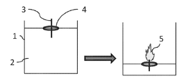
도 1a는 종래 기술에 따른 액체 양초의 제1 변형물을 도시한다. 액체 양초는 액체 연료(2)를 수취하는 연료 수취부(1), 및 액체 연료(2)의 표면에 부유하는 부유체(4) 위에 배치된 심지(3)를 포함한다. 심지(3)가 불꽃(5)에 의해 점화될 때, 액체 연료(2)가 점진적으로 소모되고, 심지(3)가 부유체(4) 위에 배치되어 있기 때문에 불꽃(5)이 점진적으로 연료 수취부(1) 내에서 하강한다. 이것은 측면에서, 즉, 도면에 대해 직교 방향으로부터 양초 시스템을 바라보는 관찰자에 대한 불꽃(5)의 가시성을 감소시킨다. 나아가, 불꽃의 가시성은 연료 수취부의 벽에 증착된 어두운 연기의 존재에 의해 추가적으로 제한될 수 있다. Figure 1A shows a first variant of a liquid candle according to the prior art. The liquid candle includes a
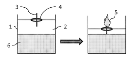
도 1b는 종래 기술에 따른 액체 양초의 제2 변형물을 도시한다. 상기에 기술된 문제점을 극복하기 위해, 연료 수취부(1) 안에 액체 연료(2)의 밀도보다 큰 밀도의 두 번째 액체(6)를 첨가하는 것이 제안되었다. 이것은 두 번째 액체(6)가 연소하지 않기 때문에 불꽃(5)가 연료 수취부(1) 바닥에 도달하는 것을 막는다. 그러나, 이 액체 양초의 제2 변형물은 액체 연료의 양이 적기 때문에 제1 변형물에 비해 감소된 연소 시간을 가지며 추가적인 액체를 필요로 하는 추가의 단점을 나타낸다. Figure 1B shows a second variant of a liquid candle according to the prior art. In order to overcome the problem described above, it has been proposed to add a
도 1c는 종래 기술에 따른 액체 양초의 제3 변형물을 도시한다. 제3 변형물에서, 심지(3)의 하단부는 연료 수취부(2)의 바닥에 고정되어 있고 심지(3)의 상부는 클립(8)에 의해 붙들려 연료 수취부(1) 밖으로 돌출되어 있다. 이것은 불꽃(5)이 연료 수취부(1) 내에서 하강하는 것을 막는다. 그러나, 액체 연료(2)와 불꽃(5) 사이의 거리가 제1 및 제2 변형물보다 멀기 때문에, 모세관 현상에 의해 불꽃(5)에 도달하는 액체 연료(2)의 양이 감소하고 따라서 생성되는 빛이 더 약해진다. Figure 1C shows a third variant of a liquid candle according to the prior art. In the third variant, the lower end of the
본 개시 내용은 종래 기술의 액체 양초 시스템의 문제점들을 적어도 일부분 극복한 신규한 액체 양초 시스템을 제공한다.The present disclosure provides a novel liquid candle system that overcomes at least in part the problems of the prior art liquid candle system.
본 출원인은 이로써 액체 양초에 의해 생성된 빛의 가시성을 개선할 수 있는 자가붕괴성 연료 수취부를 포함하는 액체 양초 시스템을 제안한다. 본 개시 내용의 주된 아이디어는 점진적으로 자가붕괴하는 연료 수취부를 사용하여 연료 수취부 내에서 연소하는 심지의 가리움을 막는 것이다. 본원에 기술될 바와 같이, 다른 기술들이 액체 양초의 연소와 함께 점진적으로 자가붕괴하는 연료 수취부를 얻기 위해 사용될 수 있다. 일부 실시양태에서, 연료 수취부는 가융성 물질로 이루어질 수 있으며 액체 양초에 의해 생성된 열이, 점화될 때, 점진적으로 연료 수취부의 에지(edge)를 융해시킨다. 일부 실시양태에서, 연료 수취부는 액체 연료가 연료 수취부 안에 수용될 때, 액체 연료에 의해 신축되고 액체 연료가 소모됨과 함께 붕괴하는 신축성 물질로 이루어질 수 있다. 일부 다른 실시양태에서, 연료 수취부는 부유 에지를 포함할 수 있고, 연료 수취부의 측벽은 액체 연료가 연소하고 부유 에지가 붕괴할 때 붕괴되도록 구성된 접을 수 있는 필름에 의해 형성될 수 있다.The Applicant proposes a liquid candle system that includes a self-collapsible fuel receiver which is thereby capable of improving the visibility of the light produced by the liquid candle. The main idea of the present disclosure is the use of a progressively self-collapsing fuel receiver to prevent clogging of the burning wick in the fuel receiver. As will be described herein, other techniques may be used to obtain a fuel receiver that progressively self-breaks with the combustion of liquid candles. In some embodiments, the fuel receiver can be made of a fusible material and the heat generated by the liquid candle gradually fuses the edge of the fuel receiver when ignited. In some embodiments, the fuel receiver may consist of a stretchable material that is stretched by the liquid fuel and collapses with the liquid fuel being consumed when the liquid fuel is received in the fuel receiver. In some other embodiments, the fuel receiver may comprise a floating edge, and the sidewall of the fuel receiver may be formed by a collapsible film configured to collapse when the liquid fuel burns and the floating edge collapses.
일반적으로, 액체 양초는 하나 이상의 심지를 포함하는 심지 배치를 포함할 수 있다. 심지는 부유체 위에 배치되거나 또는 연료 수취부에 결합될 수 있다. Generally, a liquid candle can include a wicking arrangement that includes one or more wicks. The wick can be disposed over the float or coupled to the fuel receiver.
따라서, 본 개시 내용은 소정의 액체 연료를 수취하도록 구성된 자가붕괴성 공동을 포함하는 연료 수취부; 및 심지를 포함하는 양초 시스템을 제공한다. 자가붕괴성 공동은 공동이 소정의 액체 연료로 채워지고 심지가 점화될 때 점진적으로 붕괴되도록 구성된다.Accordingly, the present disclosure provides a fuel injector comprising: a fuel receiver comprising a self-collapsible cavity configured to receive a predetermined liquid fuel; And a wick system. The self-collapsing cavity is configured to progressively collapse when the cavity is filled with a predetermined liquid fuel and the core is ignited.
일부 실시양태에서, 심지는 자가붕괴성 공동이 소정의 액체 연료로 채워질 때, 심지의 제1 단부가 공동의 개구 밖으로 돌출되도록 구성된다.In some embodiments, the wick is configured such that when the self-collapsible cavity is filled with a predetermined liquid fuel, the first end of the wick protrudes out of the cavity opening.
일부 실시양태에서, 자가붕괴성 공동은 공동 안의 소정의 액체 연료의 감소 속도와 유사한 속도로 붕괴되도록 구성된다.In some embodiments, the self-collapsible cavity is configured to collapse at a rate similar to the rate of decrease of a given liquid fuel in the cavity.
일부 실시양태에서, 자가붕괴성 공동은 신축성 물질로 이루어져, 소정의 액체 연료가 자가붕괴성 공동 안으로 수용될 때, 자가붕괴성 공동은 소정의 액체 연료에 의해 밖으로 신장되고, 자가붕괴성 공동이 소정의 액체 연료로 채워지고 심지가 점화될 때, 자가붕괴성 공동은 소정의 액체 연료가 소모됨에 따라 안으로 신축한다.In some embodiments, the self-collapsible cavity is comprised of a stretchable material such that when the desired liquid fuel is received within the self-collapsible cavity, the self-collapsible cavity is extended outwardly by the predetermined liquid fuel, Of the liquid fuel and the wick is ignited, the self-collapsible cavity expands inward as the desired liquid fuel is consumed.
일부 실시양태에서, 자가붕괴성 공동은 부유 에지에 매달린 접을 수 있는 필름에 의해 형성된 측벽에 의해 외접되어, 소정의 액체 연료로 채워질 때 자가붕괴성 공동이 팽창하고, 심지가 점화될 때 소정의 액체 연료가 소모됨에 따라 수축한다.In some embodiments, the self-collapsible cavity is circumscribed by a sidewall formed by a collapsible film suspended from the floating edge, such that when the self-collapsible cavity expands when filled with a predetermined liquid fuel and the wick is ignited, Shrinks as fuel is consumed.
일부 실시양태에서, 자가붕괴성 공동은 가융성 물질로 이루어진 측벽에 의해 외접되고 양초 시스템은, 공동이 소정의 액체 연료로 채워지고 심지의 제1 단부가 점화될 때, 측벽의 에지가 융해되도록 구성된다. In some embodiments, the self-collapsible cavity is circumscribed by a sidewall of a fusible material and the candle system is configured such that when the cavity is filled with a predetermined liquid fuel and the first end of the wick is fired, do.
일부 실시양태에서, 양초 시스템은 공동 안에 수용된 소정 부피의 액체 연료를 더 포함한다.In some embodiments, the candle system further includes a predetermined volume of liquid fuel contained within the cavity.
본 개시 내용은 또 다른 측면에서, 소정의 액체 연료를 수취하도록 구성된 자가붕괴성 공동을 포함하는 연료 수취부; 및 심지를 포함하는 양초 시스템을 제공하며; 여기서 양초 시스템은 추가로 소정 부피의 액체 연료가 자가붕괴성 공동 안에 주입될 때, 심지의 제1 단부가 액체 연료 밖으로 돌출되고, 심지의 제1 단부가 점화될 때, 자가붕괴성 공동은 공동 안의 소정의 액체 연료의 감소 속도와 유사한 속도로 붕괴되도록 구성된다.The present disclosure provides, in another aspect, a fuel cell system comprising: a fuel receiver comprising a self-collapsible cavity configured to receive a predetermined liquid fuel; And a wick; Wherein the candle system further comprises a self-collapsible cavity, wherein when a predetermined volume of liquid fuel is injected into the self-collapsible cavity, the first end of the wick protrudes out of the liquid fuel and the first end of the wick is ignited, And is configured to collapse at a rate similar to the rate of decrease of a given liquid fuel.
일부 실시양태에서, 자가붕괴성 공동은 신축성 물질로 이루어져, 소정의 액체 연료가 자가붕괴성 공동 안으로 수용될 때, 자가붕괴성 공동이 소정의 액체 연료에 의해 밖으로 신장되고, 소정의 액체 연료가 소모될 때, 자가붕괴성 공동이 붕괴한다.In some embodiments, the self-collapsible cavity is made of a stretchable material such that when the desired liquid fuel is received into the self-collapsible cavity, the self-collapsible cavity is stretched out by the predetermined liquid fuel, When it collapses, self-collapsing cavities collapse.
일부 실시양태에서, 자가붕괴성 공동은, 소정의 액체 연료 위에 부유하도록 구성된 부유 에지에 매달린 접을 수 있는 필름에 의해 형성된 측벽에 의해 외접되어 공동이 소정의 액체 연료로 채워지고 심지의 제1 단부가 점화될 때, 소정의 액체 연료가 소모됨에 따라 부유 에지가 하강한다.In some embodiments, the self-collapsing cavity is circumscribed by a sidewall formed by a collapsible film suspended from a floating edge configured to float over a predetermined liquid fuel so that the cavity is filled with the desired liquid fuel and the first end of the core When ignited, the floating edge falls as the predetermined liquid fuel is consumed.
일부 실시양태에서, 자가붕괴성 공동은 가융성 물질로 이루어진 측벽에 의해 외접되고 양초 시스템은, 공동이 소정의 액체 연료로 채워지고 심지의 제1 단부가 점화될 때, 측벽의 에지가 융해되도록 구성된다.In some embodiments, the self-collapsible cavity is circumscribed by a sidewall of a fusible material and the candle system is configured such that when the cavity is filled with a predetermined liquid fuel and the first end of the wick is fired, do.
일부 실시양태에서, 공동이 소정의 액체 연료로 채워지고 심지의 제1 단부가 점화될 때, 측벽의 에지의 융해에 의해, 공동의 개구가 공동 안의 소정의 액체 연료가 감소하는 속도와 유사한 속도로 감소하게 된다.In some embodiments, when the cavity is filled with a predetermined liquid fuel and the first end of the wick is ignited, the fusion of the edge of the sidewall causes the opening of the cavity to move at a rate similar to the rate at which certain liquid fuel in the cavity decreases .
일부 실시양태에서, 소정 양의 액체 연료가 공동의 개구까지 공동을 채운다.In some embodiments, a predetermined amount of liquid fuel fills the cavity to the cavity opening.
일부 실시양태에서, 양초 시스템은 추가로 액체 연료가 연소하는 동안 불꽃이 공동 밖에서 보이도록 구성된다.In some embodiments, the candle system is further configured so that the flame is visible outside the cavity while the liquid fuel is burning.
일부 실시양태에서, 양초 시스템은 공동 안에 수용된 소정 부피의 액체 연료를 더 포함한다.In some embodiments, the candle system further includes a predetermined volume of liquid fuel contained within the cavity.
본 개시 내용은 또 다른 측면에서, 소정의 액체 연료를 수취하도록 구성된 자가붕괴성 공동을 포함하는 연료 수취부; 저장조 표면까지 공동을 채우도록 공동 안에 수용된 소정 부피의 액체 연료; 저장조 표면 밖으로 심지의 제1 단부가 돌출되도록 구성된 심지를 포함하는 양초 시스템을 제공하며, 여기서 자가붕괴성 공동은 심지의 제1 단부가 점화될 때 점진적으로 붕괴되도록 구성된다. The present disclosure provides, in another aspect, a fuel cell system comprising: a fuel receiver comprising a self-collapsible cavity configured to receive a predetermined liquid fuel; A predetermined volume of liquid fuel contained within the cavity to fill the cavity to the reservoir surface; And a wick configured to project a first end of the wick out of the reservoir surface, wherein the self-collapsible cavity is configured to progressively collapse when the first end of the wick is ignited.
일부 실시양태에서, 심지의 제1 단부가 점화될 때, 자가붕괴성 공동이 공동 안의 소정의 액체 연료의 감소 속도와 유사한 속도로 붕괴되도록 구성된다.In some embodiments, when the first end of the wick is ignited, the self-collapsible cavity is configured to collapse at a rate similar to the rate of decrease of the predetermined liquid fuel in the cavity.
일부 실시양태에서, 자가붕괴성 공동은 신축성 물질로 이루어져, 자가붕괴성 공동은 소정의 액체 연료에 의해 밖으로 신장되고, 소정의 액체 연료가 소모될 때, 자가붕괴성 공동은 점진적으로 붕괴한다.In some embodiments, the self-collapsible cavity is made of a stretchable material, the self-collapsible cavity is stretched out by the predetermined liquid fuel, and when the predetermined liquid fuel is consumed, the self-collapsible cavity gradually collapses.
일부 실시양태에서, 자가붕괴성 공동은, 소정의 액체 연료 위에 부유하도록 구성된 부유 에지에 매달린 접을 수 있는 필름에 의해 형성된 측벽에 의해 외접되어 공동이 소정의 액체 연료로 채워지고 심지의 제1 단부가 점화될 때, 소정의 액체 연료가 소모됨에 따라 부유 에지가 하강한다.In some embodiments, the self-collapsing cavity is circumscribed by a sidewall formed by a collapsible film suspended from a floating edge configured to float over a predetermined liquid fuel so that the cavity is filled with the desired liquid fuel and the first end of the core When ignited, the floating edge falls as the predetermined liquid fuel is consumed.
일부 실시양태에서, 자가붕괴성 공동은 가융성 물질로 이루어진 측벽에 의해 외접되고 양초 시스템은, 심지의 제1 단부가 점화될 때, 측벽의 에지가 융해되도록 구성된다.In some embodiments, the self-collapsible cavity is circumscribed by a sidewall of a fusible material and the candle system is configured to melt the edge of the sidewall when the first end of the wick is ignited.
일부 실시양태에서, 저장조 표면은 공동의 개구에 도달한다.In some embodiments, the reservoir surface reaches the cavity opening.
일부 실시양태에서, 양초 시스템은 추가로 액체 연료가 연소하는 동안 불꽃이 공동 밖에서 보이도록 구성된다.In some embodiments, the candle system is further configured so that the flame is visible outside the cavity while the liquid fuel is burning.
일부 실시양태에서, 소정의 액체 연료 위에 부유할 수 있는 부유체를 더 포함하며 여기서 심지는 부유체 위에 배치된다.In some embodiments, the apparatus further includes a float capable of floating over a predetermined liquid fuel, wherein the wick is disposed over the float.
일부 실시양태에서, 심지의 제2 단부는 자가붕괴성 공동에 결합된다.In some embodiments, the second end of the wick is bonded to a self-collapsible cavity.
일부 실시양태에서, 양초 시스템은 심지를 강화하도록 구성된 심지 코팅을 더 포함한다.In some embodiments, the candle system further comprises a wicking coating configured to enhance the wick.
일부 실시양태에서, 심지 코팅은 가융성 물질로 이루어진다. In some embodiments, the wicking coating comprises a fusible material.
일부 실시양태에서, 심지 코팅은 고체 파라핀 및/또는 왁스로 만들어진다.In some embodiments, the wick coating is made of solid paraffin and / or wax.
일부 실시양태에서, 소정의 액체 연료는 올리브 오일이다.In some embodiments, the predetermined liquid fuel is olive oil.
일부 실시양태에서, 개구까지 또는 저장조 표면까지의 공동의 부피는 공동이 올리브 오일로 채워졌을 때, 30 분 내지 1 주의 범위에서 선택되는 시간의 주어진 기간에 걸쳐 양초 시스템의 조명을 가능하게 하도록 조정된다.In some embodiments, the volume of the cavity to the opening or to the reservoir surface is adjusted to allow illumination of the candle system over a given period of time selected from the range of 30 minutes to 1 week when the cavity is filled with olive oil .
일부 실시양태에서, 공동이 올리브 오일로 채워졌을 때, 개구까지 또는 저장조 표면까지의 공동의 부피가 40 분, 90 분, 3 시간, 6 시간, 8 시간, 24 시간, 48 시간, 72 시간, 1 주의 범위에서 선택되는 시간의 주어진 기간에 걸쳐 양초 시스템의 조명을 가능하게 하도록 조정된다.In some embodiments, when the cavity is filled with olive oil, the volume of the cavity to the opening or to the reservoir surface is 40 minutes, 90 minutes, 3 hours, 6 hours, 8 hours, 24 hours, 48 hours, 72 hours, 1 Is adjusted to enable illumination of the candle system over a given period of time selected in the range of interest.
일부 실시양태에서, 양초 시스템은 공동을 덮도록 구성된 가융성 커버, 가융성 커버 밖으로 돌출되도록 추가로 구성된 심지를 더 포함하며, 여기서 가융성 커버는 심지의 제1 단부가 점화될 때 융해되도록 구성된다.In some embodiments, the candle system further comprises a wicking cover configured to cover the cavity, and a wick further configured to protrude out of the fusible cover, wherein the fusible cover is configured to fuse when the first end of the wick is ignited .
일부 실시양태에서, 가융성 커버는 파라핀 및/또는 왁스로 이루어진다.In some embodiments, the fusible cover is comprised of paraffin and / or wax.
일부 실시양태에서, 양초 시스템 하나 이상의 추가적인 심지 배치를 더 포함한다.In some embodiments, the candle system further includes one or more additional wick placement.
일부 실시양태에서, 양초 시스템 하나 이상의 추가적인 연료 수취부를 더 포함한다.In some embodiments, the candle system further includes at least one additional fuel receiver.
본 개시 내용은 또 다른 측면에서, 전술한 바와 같은 하나 이상의 양초 시스템; 및 올리브 오일을 담은 하나 이상의 올리브 오일 용기를 포함하는 양초 키트를 제공한다. The present disclosure, in another aspect, provides a candle system comprising: at least one candle system as described above; And at least one olive oil container containing olive oil.
본원에 개시된 발명의 요지(subject matter)를 더 잘 이해하고 이것이 어떻게 실제로 수행될 수 있는지 예시하기 위해, 첨부된 도면들을 참조하여 오직 비제한적인 예시의 방식으로써, 실시양태들이 이제 기술될 것이다.
도 1a-1c는, 이미 기술되었듯, 종래 기술에 따른 액체 양초 시스템의 단면도를 도시한다.
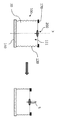
도 2a 및 도 2b는 각각 본 개시 내용의 일부 실시양태에 따른 연료 수취부의 측단면도 및 상면도를 도시한다.
도 3은 본 개시 내용의 일부 실시양태에 따른 조명 전 및 중의 양초 시스템의 측단면도를 도시한다.
도 4는 본 개시 내용의 일부 실시양태에 따른 조명 전 및 중의 양초 시스템의 측단면도를 도시한다.
도 5a 및 도 5b는 본 개시 내용의 실시양태에 따른 폐기물 수집 기작을 포함하는 양초 시스템의 측단면도를 도시한다.
도 6a 및 도 6b는 본 개시 내용의 실시양태에 따른 가융성 커버를 포함하는 양초 시스템의 측단면도를 도시한다.
도 7a 및 도 7b는 본 개시 내용의 실시양태에 따른 양초 시스템의 측단면도를 도시한다.
도 8은 본 개시 내용의 일부 실시양태에 따른 조명 전 및 중의 양초 시스템의 측단면도를 도시한다.
도 9는 본 개시 내용의 일부 실시양태에 따른 조명 전 및 중의 양초 시스템의 사시도를 도시한다.
달리 지시하지 않는 한, 다른 도면의 유사한 참조들이 유사한 구성요소를 참조할 수 있다. To better understand the subject matter of the invention disclosed herein and to illustrate how it can be carried out in practice, embodiments will now be described, by way of non-limiting example only, with reference to the accompanying drawings.
1A-1C show cross - sectional views of a liquid candle system according to the prior art, as already described.
Figure 2a and 2b show a fuel receiving portion side sectional view and a top view respectively of the some embodiments of the present disclosure.
Figure 3 shows a cross-sectional side view of a candle system during and during illumination according to some embodiments of the present disclosure;
4 shows a side cross-sectional view of a candle system during and during illumination according to some embodiments of the present disclosure;
5A and 5B show side cross-sectional views of a candle system including a waste collection mechanism in accordance with an embodiment of the present disclosure;
Figure 6a and 6b shows a cross-sectional side view of the candle system including a fusible cover according to embodiments of the present disclosure.
Figure 7a and 7b shows a side cross-sectional view of the candle system according to an embodiment of the present disclosure.
Figure 8 shows a side cross-sectional view of a candle system during and during illumination according to some embodiments of the present disclosure.
Figure 9 shows a perspective view of a candle system during and during illumination according to some embodiments of the present disclosure;
Similar references in different drawings may refer to similar elements, unless otherwise indicated.
본원에 기술된 것들은 액체 양초 시스템의 일부 예시들이다.Described herein are some examples of liquid candle systems.
용어 "가융성"은 양초 근방에서 생성된 열에 대해 쉽게 녹는 물질을 지칭하는 것으로 이해된다. 특히, 본 개시 내용에서 용어 "가융성"은 설명에 개시된 조건하에서 녹는 물질을 지칭한다. 예를 들어, 측벽은 가융성 물질로 이루어져, 점화된 심지에 의해 생성된 열이 측벽의 에지의 융해를 야기한다.The term "fusible" is understood to refer to a material that is readily soluble in heat generated near a candle. In particular, the term "fusible" in this disclosure refers to a substance that melts under the conditions described in the description. For example, the sidewall is made of a fusible material, and the heat generated by the fired wick causes the fusing of the edge of the sidewall.
용어 "붕괴하다"는 수직적 축소 (수직적 수축)를 지칭한다. 공동의 수직적 축소는 공동의 종축에 따른 축소를 지칭할 수 있는 것에 주목된다. 종축은 공동의 확장 축을 지칭할 수 있다. 이어지는 설명 및/또는 청구항에서, 용어 "수직적", "수평적," "위", "아래" 및 이와 유사한 것들은, 예를 들어 도 3 및 도 4에서 보여지는 바와 같이 (즉, 액체 연료가 연료 수취부 안에 머무를 수 있도록 연료 수취부의 개구가 이것이 붙들린 지지대에 대향하도록 배향되어 있는) 일반적으로 양초 시스템의 기준 위치를 참조하여 방향을 지칭하는 데에 사용되는 것으로 이해된다.The term "collapse" refers to vertical contraction (vertical contraction). It is noted that the vertical reduction of the cavity can refer to the reduction along the common longitudinal axis. The vertical axis may refer to the expansion axis of the cavity. In the following description and / or claims, the terms "vertical", "horizontal,""above","below", and similar things, for example, as shown in Figs. 3 and 4 (that is, the liquid fuel is fuel It is understood that the opening of the fuel receiving portion is oriented so as to face the supported support so as to be able to stay in the receiving portion) and is generally used to refer to the reference with reference to the reference position of the candle system.
나아가, 용어 "액체 연료"는 양초 조명을 위해 채택되고, 실온 및 실압 조건하에서, 특히, 점화되는 심지가 없을 때 액체인 연료를 지칭하는 것으로 이해되어야 한다. 예를 들어, 액체 연료는 올리브 오일로 구성될 수 있다. Further, the term "liquid fuel" should be understood to refer to fuels that are employed for candle lighting and that are liquid at room temperature and pressure conditions, especially when there is no ignition core. For example, the liquid fuel may be composed of olive oil.
나아가, 청구항들은 일반적으로 양초 시스템의 본래 상태, 즉, 조명 전 상태를 기술하는 것을 목적한다는 것이 주목된다. 다시 말해서, 양초 시스템을 기술하기 위해 개시된 특징들은 양초 시스템이 이미 상당 시간 동안 점화되어 이의 본래 모양 및/또는 특성이 변경된 사용 상태와 달리 미사용 상태의 양초 시스템을 기술하는 것으로 이해되어야 한다.Further, it is noted that the claims are generally intended to describe the original state of the candle system, i.e., the pre-illumination state. In other words, it should be understood that the features disclosed for describing the candle system describe the candle system in an unused state, unlike the state of use in which the candle system has already been ignited for a considerable time and its original shape and / or characteristics have changed.
이어지는 상세한 설명에서, 수많은 구체적인 세부사항들이 본 발명의 요지의 완전한 이해를 제공하기 위해 설명된다. 그러나, 발명의 요지의 일부 예시들은 이러한 구체적인 세부사항 없이 실시될 수 있음이 당업자에 의해 이해될 것이다.In the following detailed description, numerous specific details are set forth in order to provide a thorough understanding of the gist of the invention. However, it will be understood by those skilled in the art that some of the gist of the invention may be practiced without these specific details.
본원에서 사용된 바와 같이, 구 "예를 들어", "예컨대", "이를 테면" 및 이들의 변형체들은 본 발명의 요지의 비제한적인 예시를 기술한다. As used herein, the terms "for example "," for example ", "such as," and variations thereof describe non-limiting examples of the gist of the invention.
"한 예시", "일부 예시", "또 다른 예시", "다른 예시", "한 사례", "일부 사례", "또 다른 사례", "다른 사례", "한 경우", "일부 경우", "또 다른 경우", "다른 경우" 또는 이들의 변형체들에 대한 본 명세서의 참조는 기술된 특정 특징, 구조 또는 특성이 발명의 요지의 하나 이상의 예시에 포함되어 있음을 의미하지만, 동일한 용어의 출현이 반드시 동일한 예시를 참조하는 것은 아니다. It should be understood that the terms "one example", "some examples", "another example", "another example", "one case", "some cases", " Quot ;, "other case "," other case ", or variations thereof, means that a particular feature, structure, or characteristic described is included in one or more examples of the gist of the invention, Does not necessarily refer to the same example.
본원에 개시된, 명확성을 위해서, 별도의 예시들의 맥락에서 기술된 특정 특징, 구조 및/또는 성질들은 단일 예시의 조합에서도 제공될 수 있음이 이해되어야 한다. 반대로, 본원에 개시된, 간결성을 위해서, 단일 예시의 맥락에서 기술된 다양한 특징, 구조 및/또는 특성들은 별도로 또는 임의의 적절한 하위 조합으로도 제공될 수 있다. 특히, 기술된 심지 배치의 두 가지 실시양태 (즉, 연료 수취부에 결합되거나 부유체 위에 배치된 심지)는 본 개시내용에 따른 자가붕괴성 연료 수취부의 다양한 실시양태에서 파악될 수 있음이 이해된다. It should be understood that, for clarity, the specific features, structures, and / or properties described in the context of separate examples may be provided in a single combination of examples. Conversely, for simplicity, as disclosed herein, various features, structures and / or characteristics described in the context of a single example may be provided separately or in any suitable subcombination. In particular, it is understood that two embodiments of the described wicking arrangement (i. E. Wick attached to the fuel receiver or disposed above the float) can be identified in various embodiments of the self-collapsible fuel receiver in accordance with the present disclosure .
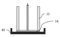
도 2a 및 도 2b는 본 개시 내용의 일부 실시양태에 따른 자가파괴성(self-destroying) 공동을 포함하는 양초 시스템의 연료 수취부(10)를 도시한다. 연료 수취부(10)는 공동(11)을 측면으로 외접하는 (둘러싸는) 측벽(12)을 포함할 수 있다. 측벽(12)의 에지(상부 크레스트(crest))(17)는 공동(11)의 개구(13)를 정의할 수 있으며 연료 수취부의 기저벽(14)은 공동(11)의 하단부를 형성할 수 있다. 공동(11)은 소정의 액체 연료, 예를 들어 올리브 오일을 수취하도록 구성된 오목부를 형성할 수 있다. 개구(13)는 공동(11) 안으로의 유체 도입을 가능하게 할 수 있다. 측벽(12)은 가융성 물질로 이루어질 수 있다. 가융성 물질은 예를 들어 다음의 물질 중 어느 하나 또는 조합으로 이루어질 수 있다: 스테아린, 밀랍, 지방 등. 기저벽(14) 역시 가융성 물질로 구성될 수 있다. 일부 실시양태에서, 기저벽(14)은 측벽(12)과 통합되어 있을 수 있다. 일부 실시양태에서, 기저벽(14)은 측벽(12)에 결합될 수 있으나, 다른 물질 (가융성 또는 비가융성)로 만들어져 있을 수 있다. 일부 실시양태에서, 측벽(12)은 환상의 수평적 단면을 가질 수 있으며 그로써 관형 공동(11)을 정의한다. 일반적으로, 측벽(12)은 공동(11)의 중심축 X (수직적 축)에 대해 축 방향으로 대칭적인 모양을 가질 수 있다. 일부 실시양태에서, 공동은 직사각형 또는 사각형의 수평적 단면을 가질 수 있다. Figure 2a and 2b show a
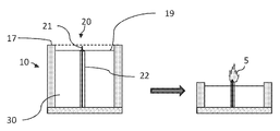
도 3은 본 개시 내용의 실시양태에 따른 양초 시스템의 제1 변형물을 도시한다. 간결성과 명확성을 위해, 연료 수취부의 특정 특성뿐만 아니라 연료 수취부의 구성요소에 관한 특정 참조 번호는 도 3 및 아래 기술에서 반복되지 않는다. 양초 시스템은 전술한 바와 같은 연료 수취부(10) 및 공동의 저장조 표면(19) 밖으로 심지(21)의 제1 단부가 돌출되도록 구성된 심지(21)를 포함할 수 있다. 도시된 바와 같이, 제1 변형물에서, 심지(21)의 제2 단부는 기저벽에 (바람직하게는 X축을 따라서) 결합될 수 있으며 저장조 표면(19) 너머 또는 바람직하게는 공동의 개구 위로 확장될 수 있다. 사실상, 저장조 표면(19)은 개구 표면 아래의 허용 수위(tolerance level)로 이해될 수 있다. 저장조 표면(19)의 수위는, 예컨대 측벽/심지 조성 및/또는 측벽의 두께와 같은 양초 시스템의 다른 특성에 의존할 수 있다. 용어 저장조 표면은 공동 내의 수위를 지칭하는 것으로 이해되며, 여기서 수위는 공동의 수직적 축, 예를 들어 이전에 정의된 X축에 대해 측정될 수 있다. 심지가 저장조 표면(19)으로부터 나타나고 액체 연료가 공동을 저장조 표면(19)까지 채울 때, 측벽의 에지의 조절된 융해라는 목적하는 효과가 일어날 수 있다. 심지가 저장조 표면(19)까지 도달하지 못하면, 목적하는 효과는 일어나지 않을 수 있다. 양초 시스템의 제1 변형물에서, 심지(21)의 제1 단부는 공동이 적어도 저장조 표면(19)까지 소정의 액체 연료(30)로 채워질 때뿐만 아니라 공동이 저장조 표면(19)까지 소정의 액체 연료(30)로 채워지지 않을 때에도 저장조 표면(19)밖으로 돌출될 수 있음이 주목된다. 저장조 표면(19)은 공동의 개구와 평행할 수 있다. 저장조 표면(19)은 공동을 마주하는 측벽(12)의 내면에 게이지 지표(gauge indication)로 표시될 수 있다. 저장조 표면(19)은 공동의 개구에 근접할 수 있어 심지(21)가 불꽃에 의해 점화될 때, 불꽃이 공동 밖에서 보인다 (또는 대부분 보인다). 저장조 표면(19)은, 심지(21)가 불꽃에 의해 점화될 때, 불꽃에 의해 생성된 열이 측벽의 에지(17)의 융해를 야기하도록 구성될 수 있다. 일부 실시양태에서, 저장조 표면(19) 및 공동의 개구는 중첩되어 있을 수 있다. 양초 시스템은 심지(21)와 함께 심지 배치(20)을 형성할 수 있는 심지(21)를 강화하도록 구성된 심지 코팅(22)을 더 포함할 수 있다. 심지 코팅(22)은 하나 이상의 가융성 물질, 예를 들어 스테아린, 밀랍, 지방 등으로 이루어질 수 있다. 심지 코팅(22)은 적어도 심지(21)의 특정 영역에서 다공성일 수 있다. 심지는 대안적으로 당업자에게 보통 쓰이는 뻣뻣한 심지일 수 있다. Figure 3 shows a first modification of the candle system according to embodiments of the present disclosure. For the sake of brevity and clarity, specific reference numbers for the components of the fuel receiver as well as specific characteristics of the fuel receiver are not repeated in FIG. 3 and the following description. The candle system may include a
측벽 및 심지(21)는, 공동이 액체 연료(30)을 담고 있고 심지(21)의 제1 단부가 불꽃(5)에 의해 점화될 때, 액체 연료(30)가 불꽃(5)에 공급되고 불꽃(5)에 의해 생성된 열이 측벽의 에지(17)가 융해되도록 구성될 수 있다. 일부 실시양태에서, 공동이 공동의 저장조 표면(19)까지 액체 연료(30)로 채워지고 심지(21)의 제1 단부가 점화될 때, 측벽의 에지(17)가 융해된다. 이것은 공동의 개구가 공동 안의 소정의 액체 유체의 줄어듦을 따르도록 야기한다. 이것은 액체 연료(30)가 연소하는 동안 불꽃(5)이 공동 밖에서 계속 보여지도록 한다. 바람직하게는, 공동의 개구는 소정의 액체 연료(30)가 감소하는 속도와 유사한 속도로 감소될 수 있다. 다시 말해서, 공동의 기하학적 구조, 심지의 위치뿐만 아니라 심지/소정의 액체 연료/측벽의 연소 특성은 심지에 의해 생성된 열이 측벽의 에지를 목적하는 속도로 융해시킬 수 있도록 설계될 수 있다. 예를 들어, 상기에 기술된 양초 시스템을 제조하는 기본적인 방법은 고전적인 촛대의 심지 주위에 관형 공동을 굴착하는 것을 포함할 수 있다. 보다 진보된 방법은 주조 및/또는 딥핑 등을 포함할 수 있다.The sidewalls and the
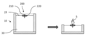
도 4는 본 개시 내용의 실시양태에 따른 양초 시스템의 제2 변형물을 도시한다. 제1 및 제2 변형물 간의 단순 차이점은 심지가 심지의 제1 단부가 저장조 표면 밖으로 돌출되도록 구성되는 방식에 관련된다. 이하의 기술은 따라서 제1 변형물에 대한 차이점에 주안점을 두며, 제1 변형물에서 기술된 세부사항들은 일반적으로 제2 변형물과 호환된다고 이해된다. 양초 시스템은 전술한 바와 같은 연료 수취부(10) 및 심지(210)를 포함할 수 있다. 양초 시스템은 소정의 액체 연료(30) 위에 부유하도록 구성된 부유체(220)를 더 포함한다. 심지(210)는 심지(210)가 부유체(220)의 제1 및 제2 면 양면 밖으로 돌출되도록 부유체(220) 위에 배치될 수 있다. 부유체(220) 및 심지(210)는 심지 배치(200)를 형성할 수 있다. 양초 시스템은 액체 연료(30)의 소정 부피가 공동 안에 수용될 때, 심지(210)의 제1 단부가 저장조 표면(19) 밖으로 돌출되도록 추가로 구성될 수 있다. 제2 변형물에서, 저장조 표면(19) 밖으로 심지의 제1 단부의 돌출은 공동 안의 소정 부피의 액체 연료의 존재에 의존하는 것이 주목된다. 나아가, 측벽(12), 심지(21) (즉, 특히 그 조성 및 크기) 및 저장조 표면(19) (즉, 공동 안에 수용될 액체 연료의 최소 부피)은 공동(11)이 액체 연료(30)를 적어도 저장조 표면(19)까지 담고 있고 심지(21)의 제1 단부가 불꽃(5)에 의해 점화될 때, 액체 연료(30)가 불꽃(5)에 공급되고 불꽃(5)에 의해 생성된 열이 측벽(12)의 에지(17)의 융해를 야기하도록 구성될 수 있다. 상술한 바와 같이, 제2 변형물에서, 심지의 위치는 공동 안에 주입된 액체 연료의 부피에 의존한다. 일부 실시양태에서, 공동이 공동의 저장조 표면(19)까지 액체 연료(30)로 채워지고 심지(21)의 제1 단부가 점화될 때, 측벽(12)의 에지(17)가 융해되고 이로써 공동의 개구가 공동 안의 소정의 액체 유체의 줄어듦을 따르도록 야기한다. 이것은 액체 연료(30)가 연소하는 동안 불꽃(5)이 공동 밖에서 계속 보여지도록 한다. 바람직하게는, 공동의 개구는 소정의 액체 연료(30)가 감소하는 속도와 유사한 속도로 감소될 수 있다. 다시 말해서, 공동의 기하학적 구조, 저장조 표면의 위치 (즉, 양초 시스템 안에 주입될 소정 부피의 액체 연료)뿐만 아니라 심지/액체 연료/측벽의 연소 특성은 심지에 의해 생성된 열이 측벽의 에지를 목적하는 속도로 융해시킬 수 있도록 선택될 수 있다. 따라서, 양초 시스템은 소정 부피의 액체 연료(30)가 공동 안에 수용되고 심지의 제1 단부가 점화될 때, 측벽의 에지(17)가 융해되고 공동의 개구가 공동 안의 소정의 액체 연료가 감소하는 속도와 유사한 속도로 감소하는 것을 야기하도록 구성될 수 있다. 액체 연료의 감소 속도뿐만 아니라 공동의 개구의 감소 속도도 예를 들어 수직적 X축에 대해 측정될 수 있음이 이해된다. 일부 실시양태에서 부유체(220)는 실질적으로 저장조 표면(19)을 덮도록 형성될 수 있다. 상기에 기술된 바와 같이, 일부 실시양태에서, 저장조 표면은 공동의 개구 위에 놓일 수 있다. 4 shows a second variant of a candle system according to an embodiment of the present disclosure; The simple difference between the first and second variants is related to the manner in which the wick is configured so that the first end of the wick protrudes out of the reservoir surface. The following description thus focuses on the differences to the first variant, and it is understood that the details described in the first variant are generally compatible with the second variant. The candle system may include the
도 5a 및 도 5b는 폐기물 수집 기작을 더 포함하는 양초 시스템의 실시양태를 도시한다. 도 5a에서 보여지는 일부 실시양태에서, 기저벽(14)은 측벽의 융해 및 액체 연료의 연소로부터 나온 폐기물을 수집하도록 측면으로 확장될 수 있다. 기저벽(14)은 임의로 주변 리지(ridge)(19)를 포함할 수 있다. 도 5b에서 보여지는 일부 대안적인 실시양태에서, 양초 시스템은 대안적으로 기저벽(14) 아래에 배치된 팬(pan)(40)을 포함할 수 있다. Figures 5A and 5B illustrate an embodiment of a candle system further comprising a waste collection mechanism. In some embodiments shown in Figure 5A , the
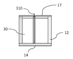
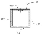
도 6a 및 도 6b는 각각 전술한 양초 시스템의, 공동의 개구를 덮도록 구성된 가융성 커버(17)를 더 포함하는 제1 및 제2 변형물의 실시양태를 도시한다. 도 6a 및 도 6b에서 보여지듯이, 양초 시스템은 소정의 액체 연료(30)를 더 포함할 수 있다. 도 6a에 기술된 제1 변형물에서, 심지(310)는 가융성 커버(17) 밖으로 돌출되도록 더 구성된다. 가융성 커버(17)는 심지(310)의 제1 단부가 점화될 때 융해되도록 구성된다. 도 6b에서 보여지듯이, 제2 변형물에 따른 양초 시스템은 심지(410)의 제1 단부가 가융성 커버(17) 밖으로 드러날 수 있도록 소정의 양의 액체를 더 포함할 수 있다. 가융성 커버(17)는 특히 양초 시스템을 쉽게 운송할 수 있게 한다. 가융성 커버(17)는 예컨대 스테아린, 지방, 왁스, 파라핀 등과 같은 하나 이상의 가융성 물질로 이루어질 수 있다. Figure 6a and 6b show a first embodiment and a second modified embodiment of water further includes a
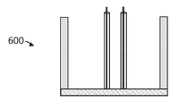
도 7a 및 도 7b는 각각 본 개시 내용의 일부 실시양태에 따른 두 개의 양초 시스템(500), (600)의 예시를 제공한다. 양초 시스템(500)은 이전에 개시된 바와 같이 다수의 양초 시스템을 포함할 수 있다. 일부 실시양태에서, 상기 양초 시스템은 공통 기저벽(18)을 공유할 수 있다. 나아가, 공유된 기저벽(18)은 공유된 기저벽(18)을 원하는 크기로 절단할 수 있게 함으로써 주어진 개수의 양초 시스템을 포함하도록 구성된 절단부(15)를 포함할 수 있다. 일부 실시양태에서, 두 개의 절단부(18)는 두 양초 시스템을 연결하는 측벽의 각 부분(15)의 양초 시스템에 인접하도록 배치될 수 있다. 양초 시스템(600)은 전술한 바와 같은 자가파괴성 연료 수취부 및 두 개의 심지를 포함한다. 일부 실시양태에서, 두 개 초과의 심지가 연료 수취부 안에 배치될 수 있다. Figures 7a and 7b provide an example of the two
도 8은 본 개시 내용의 일부 실시양태에 따른, 공동의 자가붕괴성이 부유 에지에 매달린 접을 수 있는 (바람직하게는 아코디언 형상) 측벽을 포함하는 연료 수취부를 가짐으로써 얻어지는 자가붕괴성 공동을 포함하는 제3 변형물에 의한 양초 시스템을 도시한다. 제1 및 제2 변형물이 단지 서로 심지 배치의 측면에서만 다름에 비해, 제3 변형물은 제1 및 제2 변형물과 연료 수취부의 구성의 측면에서 다름이 주목된다. 따라서, 간결성을 위해서, 이하의 기술은 제1 및 제2 변형물의 관점에서의 차이점에 주안점을 두며, 제1 및 제2 변형물에서 기술된 세부사항들은 일반적으로 제3 변형물과 호환된다고 이해된다 (그 역도 마찬가지). 특히 제3 변형물은 제1 및 제2 변형물 중 임의의 것에 따른 심지 배치를 아우른다. 도 8에서, 양초 시스템은 도 4를 참조하여 기술된 바와 같이 심지 배치(200)와 함께 보여진다. 액체 양초 시스템은 심지 배치 및 소정의 액체 연료를 수용하도록 구성된 자가붕괴성 공동(111)을 갖는 연료 수취부(100)를 포함할 수 있다. 연료 수취부(100)는 측벽(120), 기저벽(140) 및 부유 에지(170)를 포함할 수 있다. 측벽(120)은 자가붕괴성 공동(111)을 측면으로 외접 (둘러싸는)할 수 있고 접을 수 있는 (즉, 유연한, 구겨지는) 필름에 의해 형성될 수 있다. 접을 수 있는 필름은 비탄성 물질로 만들어질 수 있다. 기저벽(140)은 자가붕괴성 공동(111)의 하단부를 형성하도록 측벽(120)에 결합될 수 있다. 기저벽(140)은 경질 플라스틱으로 이루어질 수 있다. 측벽(120)의 에지는 부유 에지(170)에 결합될 수 있다. 일부 실시양태에서, 부유 에지(170)는 고리 모양을 가질 수 있고 측벽(120)의 에지는 부유 에지(170)에 래핑(wrapped)될 수 있다. 부유 에지(170)는 소정의 액체 연료(30) 위에 부유하도록 구성된 물질로 만들어질 수 있다. 공동(111)은 소정의 액체 연료(30), 예를 들어 올리브 오일을 수취하도록 구성된 소모성 오목부를 형성할 수 있다. 소정의 액체 연료(30)가 공동(111) 안에 주입될 때, 공동(111)은 (수직적 X축에 대하여) 신축성 있게(telescopically) 팽창할 수 있다. 불꽃(5)에 의해 심지가 점화되고 액체 연료가 소모될 때, 공동(111)은 액체 연료(30)의 수위가 줄어듦과 함께 신축성 있게 후퇴할 수 있다. 연료 수취부(100)는 부유 에지(170)를 지지할 수 있도록 구성된 기둥 세트 (미도시)를 더 포함할 수 있다. 일부 실시양태에서, 기둥들은 신축적(telescopic)일 수 있다. 공동의 개구는 공동(111) 안으로의 유체 도입을 가능하게 할 수 있다. 접을 수 있는 필름의 두께는 30 내지 수 백 마이크로미터 사이, 예를 들어 300 마이크로미터일 수 있다. 접을 수 있는 필름은 예를 들어 나일론 및/또는 플라스틱으로 이루어질 수 있다. 부유 에지(170)는 연소 중인 심지에 의해 생성된 열에 견딜 수 있다. 일부 실시양태에서, 제3 변형물에 따른 양초 시스템에서, 심지의 제2 단부가 기저벽(140)에 결합되며 클립 (미도시)이 심지 스탠딩(standing)을 붙들기 위해 더 제공될 수 있다. 클립은 심지가 클립 밖으로 돌출되도록 하기 위해 중앙 홀(center hole)과 함께 제공될 수 있다. 다시 말해서, 연료 수취부는 (측벽에 대해서) 주로 부드러운 붕괴성 플라스틱으로 이루어질 수 있다. 공동이 채워짐에 따라, 측벽의 꼭대기와 연결된 부유 에지가 상승하고 붕괴가능한 플라스틱 측벽을 이와 함께 집어든다. 부유 에지는 오직 측벽을 따라 (인접하여) 있을 수 있고 공동의 개구 전체를 덮지 않을 수 있다. 심지는 부유 에지 안에 주입되지 않을 수 있다. 불이 액체 연료를 연소시킴에 따라, 부유 에지가 연료 수취부의 측벽을 낮춘다. Figure 8 is a cross-sectional view of an embodiment of a self-collapsible catheter including a self-collapsible cavity obtained by having a fuel receiving portion including a collapsible (preferably accordion-shaped) Figure 3 shows a candle system with a third variant. It is noted that the third variant differs in terms of the configuration of the first and second variants and the fuel receiver, as compared with the first and second variants differing only in terms of the wick arrangement with respect to each other. Thus, for brevity, the following description focuses on the differences in terms of the first and second variants, and it is understood that the details described in the first and second variants are generally compatible with the third variant (And vice versa). In particular, the third variant encompasses the wicking arrangement along any of the first and second variants. 8, the candle system is shown with the
도 9는 본 개시 내용의 일부 실시양태에 따른 자가붕괴성 공동을 포함하는 제4 변형물에 따른 양초 시스템을 도시한다. 제4 변형물은 전술한 두 타입의 심지 배치 중 임의의 것과 함께 사용될 수 있다. 도 9에서, 양초 시스템은 도 4를 참조하여 기술된 바와 같은 심지 배치(200)와 함께 보여진다. 액체 양초 시스템은 심지 및 소정의 액체 연료를 수용하도록 구성된 자가붕괴성 공동을 갖는 연료 수취부(1000)를 포함할 수 있다. 자가붕괴성 공동은 에지 고리(1017) 위에 얹어진 탄성 측벽(1012)에 의해 형성될 수 있다. 에지 고리(1017)는 기둥(1014)에 배치될 수 있다. 기둥(1014)은 수직적으로 배치될 수 있으며 에지 고리(1017)를 기둥(1014)에 직교하도록 유지하기 위해 구성될 수 있다. 탄성 측벽(1012)은 신축성 물질로 만들어질 수 있어, 소정의 액체 연료가 자가붕괴성 공동 안으로 수용될 때, 자가붕괴성 공동은 소정의 액체 연료에 의해 밖으로 신장되고, 공동이 소정의 액체 연료로 채워지고 심지의 제1 단부가 점화될 때, 자가붕괴성 공동은 소정의 액체 연료가 소모됨에 따라 안으로 신축한다. Figure 9 illustrates a candle system in accordance with a fourth variant including a self-collapsible cavity in accordance with some embodiments of the present disclosure. The fourth variant can be used with any of the two types of wicking arrangements described above. 9, the candle system is shown with the
상기 예시와 기술들은 물론 오직 도시의 목적을 위해 제공되었으며, 어떠한 방식으로도 본 발명을 제한하려는 의도가 아니다. 당업자에 의해 이해될 바와 같이, 본 발명은 본 발명의 범위를 초과하지 않으면서 상술한 기술 중 하나 초과를 이용하는 매우 다양한 방법으로 수행될 수 있다.The above examples and techniques are provided for city purposes only and are not intended to limit the invention in any way. As will be appreciated by those skilled in the art, the present invention may be practiced in a wide variety of ways using one or more of the above-described techniques without exceeding the scope of the present invention.
Claims (35)
- 심지
를 포함하고,
여기서 자가붕괴성 공동은 공동이 소정의 액체 연료로 채워지고 심지가 점화될 때 점진적으로 붕괴되도록 구성된, 양초 시스템.A fuel receiver comprising a self-collapsible cavity configured to receive a predetermined liquid fuel; And
- Wick
Lt; / RTI >
Wherein the self-collapsible cavity is configured to progressively collapse when the cavity is filled with a predetermined liquid fuel and the core is ignited.
- 심지
를 포함하고,
여기서 소정 부피의 액체 연료가 자가붕괴성 공동 안으로 주입될 때, 심지의 제1 단부가 액체 연료 밖으로 돌출되고, 심지의 제1 단부가 점화될 때, 자가붕괴성 공동은 공동 안의 소정의 액체 연료의 감소 속도와 유사한 속도로 붕괴되도록 추가로 구성된 양초 시스템.A fuel receiver comprising a self-collapsible cavity configured to receive a predetermined liquid fuel; And
- Wick
Lt; / RTI >
When a predetermined volume of the liquid fuel is injected into the self-collapsible cavity, when the first end of the wick protrudes out of the liquid fuel and the first end of the wick is ignited, the self- The candle system further configured to collapse at a rate similar to the reduction rate.
- 저장조 표면까지 공동을 채우도록 공동 안에 수용된 소정 부피의 액체 연료;
- 저장조 표면 밖으로 심지의 제1 단부가 돌출되도록 구성된 심지
를 포함하고,
여기서 자가붕괴성 공동이 심지의 제1 단부가 점화될 때 점진적으로 붕괴되도록 구성된 양초 시스템.A fuel receiver comprising a self-collapsible cavity configured to receive a predetermined liquid fuel;
A predetermined volume of liquid fuel contained in the cavity to fill the cavity to the reservoir surface;
- a wick configured to project the first end of the wick out of the reservoir surface
Lt; / RTI >
Wherein the self-collapsible cavity is configured to progressively collapse when the first end of the wick is ignited.
- 올리브 오일을 담은 하나 이상의 올리브 오일 용기
를 포함하는 양초 키트.
- at least one candle system according to any of the claims 1 to 34; And
- One or more olive oil bottles containing olive oil
≪ / RTI >
Applications Claiming Priority (3)
| Application Number | Priority Date | Filing Date | Title |
|---|---|---|---|
| IL228306A IL228306B (en) | 2013-09-09 | 2013-09-09 | Liquid candle system |
| IL228306 | 2013-09-09 | ||
| PCT/IL2014/050799 WO2015033347A1 (en) | 2013-09-09 | 2014-09-09 | Liquid candle system |
Publications (1)
| Publication Number | Publication Date |
|---|---|
| KR20160053980A true KR20160053980A (en) | 2016-05-13 |
Family
ID=51221221
Family Applications (1)
| Application Number | Title | Priority Date | Filing Date |
|---|---|---|---|
| KR1020167009090A KR20160053980A (en) | 2013-09-09 | 2014-09-09 | Liquid candle system |
Country Status (12)
| Country | Link |
|---|---|
| US (1) | US20160223186A1 (en) |
| EP (1) | EP3044296A4 (en) |
| JP (1) | JP6556729B2 (en) |
| KR (1) | KR20160053980A (en) |
| CN (1) | CN105593355A (en) |
| AU (1) | AU2014316647B2 (en) |
| CA (1) | CA2923584A1 (en) |
| IL (1) | IL228306B (en) |
| MX (1) | MX2016003004A (en) |
| RU (1) | RU2016112967A (en) |
| SG (1) | SG11201601336TA (en) |
| WO (1) | WO2015033347A1 (en) |
Cited By (2)
| Publication number | Priority date | Publication date | Assignee | Title |
|---|---|---|---|---|
| WO2020171609A1 (en) * | 2019-02-19 | 2020-08-27 | 주식회사 엘드낙 | Apparatus for generating light |
| KR102258525B1 (en) * | 2020-02-19 | 2021-05-31 | 안상정 | Apparatus of generating light |
Families Citing this family (1)
| Publication number | Priority date | Publication date | Assignee | Title |
|---|---|---|---|---|
| GB2531493B (en) * | 2014-05-30 | 2020-02-12 | Madalura Jenny | Wicks for liquid-fuelled candles |
Family Cites Families (20)
| Publication number | Priority date | Publication date | Assignee | Title |
|---|---|---|---|---|
| US3428409A (en) * | 1966-09-06 | 1969-02-18 | James R Summers | Rigid wick,rigid core-wick and rigidized candle |
| JPS5182379U (en) * | 1974-12-25 | 1976-07-01 | ||
| CN2032675U (en) * | 1988-01-21 | 1989-02-15 | 扬祥玉 | Teardropless candle |
| CN2113275U (en) * | 1991-10-22 | 1992-08-19 | 张志刚 | Liquid candle |
| IL104344A (en) * | 1992-10-08 | 2000-07-16 | Elharar Shimon | Candle |
| CA2125118C (en) * | 1994-06-03 | 2002-03-19 | Gerard Auger | Reusable candle |
| JPH08212818A (en) * | 1994-10-27 | 1996-08-20 | Pegasus Candle Kk | Liquid burning agent for light illuminating body and light illuminating body |
| US5927964A (en) * | 1997-08-05 | 1999-07-27 | Transmet Corporation | Candle with embedded metal particulates |
| US6439880B1 (en) * | 2000-02-11 | 2002-08-27 | Robert Ray | Clear candle construction |
| US20020127507A1 (en) * | 2001-03-12 | 2002-09-12 | Billilyn Long | Gel candle in a flexible container |
| US6579090B1 (en) * | 2002-02-27 | 2003-06-17 | Robert Taubitz | Liquid fuel burner |
| US20040000088A1 (en) * | 2002-07-01 | 2004-01-01 | Wesley John N. | Cleaner-burning liquid candle fuel and candle made therefrom |
| JP3093463U (en) * | 2002-10-17 | 2003-05-09 | ムラエ商事株式会社 | Oil lamp |
| CN2746268Y (en) * | 2004-10-13 | 2005-12-14 | 王红侠 | Candlestick |
| CN2806475Y (en) * | 2005-06-28 | 2006-08-16 | 步金良 | Combined candle |
| CN2883928Y (en) * | 2006-02-23 | 2007-03-28 | 孙颖 | Clean candle |
| US20080081305A1 (en) * | 2006-09-29 | 2008-04-03 | The Procter & Gamble Company | Candle having visually distinct regions |
| CN201202989Y (en) * | 2008-04-04 | 2009-03-04 | 遂昌千赢工业品设计有限公司 | Durable candle |
| CN201416762Y (en) * | 2008-12-03 | 2010-03-03 | 胡毓瑱 | Smokeless light candle |
| US8882495B2 (en) * | 2010-04-20 | 2014-11-11 | Catalina Navarro | Environmentally friendly packaging assembly and a candle embodying the same |
-
2013
- 2013-09-09 IL IL228306A patent/IL228306B/en active IP Right Grant
-
2014
- 2014-09-09 EP EP14841525.0A patent/EP3044296A4/en not_active Withdrawn
- 2014-09-09 JP JP2016542435A patent/JP6556729B2/en not_active Expired - Fee Related
- 2014-09-09 SG SG11201601336TA patent/SG11201601336TA/en unknown
- 2014-09-09 CA CA2923584A patent/CA2923584A1/en not_active Abandoned
- 2014-09-09 KR KR1020167009090A patent/KR20160053980A/en not_active Application Discontinuation
- 2014-09-09 WO PCT/IL2014/050799 patent/WO2015033347A1/en active Application Filing
- 2014-09-09 MX MX2016003004A patent/MX2016003004A/en unknown
- 2014-09-09 US US14/917,608 patent/US20160223186A1/en not_active Abandoned
- 2014-09-09 RU RU2016112967A patent/RU2016112967A/en not_active Application Discontinuation
- 2014-09-09 CN CN201480053642.6A patent/CN105593355A/en active Pending
- 2014-09-09 AU AU2014316647A patent/AU2014316647B2/en not_active Ceased
Cited By (2)
| Publication number | Priority date | Publication date | Assignee | Title |
|---|---|---|---|---|
| WO2020171609A1 (en) * | 2019-02-19 | 2020-08-27 | 주식회사 엘드낙 | Apparatus for generating light |
| KR102258525B1 (en) * | 2020-02-19 | 2021-05-31 | 안상정 | Apparatus of generating light |
Also Published As
| Publication number | Publication date |
|---|---|
| RU2016112967A (en) | 2017-10-16 |
| IL228306B (en) | 2020-10-29 |
| JP6556729B2 (en) | 2019-08-07 |
| WO2015033347A1 (en) | 2015-03-12 |
| CN105593355A (en) | 2016-05-18 |
| SG11201601336TA (en) | 2016-03-30 |
| RU2016112967A3 (en) | 2018-06-19 |
| CA2923584A1 (en) | 2015-03-12 |
| JP2016534214A (en) | 2016-11-04 |
| MX2016003004A (en) | 2016-06-02 |
| IL228306A0 (en) | 2014-06-30 |
| US20160223186A1 (en) | 2016-08-04 |
| AU2014316647B2 (en) | 2018-04-12 |
| EP3044296A1 (en) | 2016-07-20 |
| EP3044296A4 (en) | 2017-05-17 |
| AU2014316647A1 (en) | 2016-03-24 |
Similar Documents
| Publication | Publication Date | Title |
|---|---|---|
| ES2261481T3 (en) | CANDLE UNDERSTANDING A CONTAINER AND A DATE SUSTAINER. | |
| CA2617988C (en) | Fuel charge for melting plate candle assembly and method of supplying liquefied fuel to a wick | |
| WO1998045650A1 (en) | Anti-flash wick sustainer and pedestal | |
| US10519399B2 (en) | Candle with scent | |
| KR20160053980A (en) | Liquid candle system | |
| US20030064340A1 (en) | Flame-resistant sheet with candle wick support | |
| US20080227043A1 (en) | Disposable, floating, flame heated wax melting plate for confined and unconfined conventional candles and attachment method for use in candle making | |
| US3495924A (en) | Method of manufacturing and use of combustible insert sleeves in the body of solid fuel heaters | |
| US20050227190A1 (en) | Candle with low melt temperature fuel region for extinguishing | |
| KR102173270B1 (en) | Eco-friendly Candle Structure | |
| KR20170054745A (en) | Candle | |
| KR20180006267A (en) | Floating candle | |
| KR102431646B1 (en) | Candle equipped with standing element for wick | |
| JP7284898B2 (en) | Core unit used for lamp and lamp using same | |
| KR101120595B1 (en) | Ability candle cover and candlestick | |
| KR200182528Y1 (en) | wick support is formed candle | |
| JP6608736B2 (en) | Candle | |
| JP2008257869A (en) | Oil storing container, float object, and oil float set equipped with them | |
| CN103756795A (en) | Fuel oil reflowing fixed candle | |
| CN205313500U (en) | Candle that is article font | |
| JP3185090U (en) | Candles and candles in containers, core spacers | |
| JP5958687B2 (en) | Candles and candle production methods | |
| JP3050529U (en) | Candle holder | |
| CN203683510U (en) | Returned fuel oil fixed candle | |
| JP2606225Y2 (en) | Floating candle holder |
Legal Events
| Date | Code | Title | Description |
|---|---|---|---|
| A201 | Request for examination | ||
| E902 | Notification of reason for refusal | ||
| E601 | Decision to refuse application |