KR20160052391A - An Undercarriage for a Working Machine - Google Patents
An Undercarriage for a Working Machine Download PDFInfo
- Publication number
- KR20160052391A KR20160052391A KR1020150151365A KR20150151365A KR20160052391A KR 20160052391 A KR20160052391 A KR 20160052391A KR 1020150151365 A KR1020150151365 A KR 1020150151365A KR 20150151365 A KR20150151365 A KR 20150151365A KR 20160052391 A KR20160052391 A KR 20160052391A
- Authority
- KR
- South Korea
- Prior art keywords
- traveling body
- lower traveling
- body according
- chassis
- linear actuator
- Prior art date
Links
Images


Classifications
-
- E—FIXED CONSTRUCTIONS
- E02—HYDRAULIC ENGINEERING; FOUNDATIONS; SOIL SHIFTING
- E02F—DREDGING; SOIL-SHIFTING
- E02F9/00—Component parts of dredgers or soil-shifting machines, not restricted to one of the kinds covered by groups E02F3/00 - E02F7/00
- E02F9/08—Superstructures; Supports for superstructures
- E02F9/085—Ground-engaging fitting for supporting the machines while working, e.g. outriggers, legs
-
- E—FIXED CONSTRUCTIONS
- E02—HYDRAULIC ENGINEERING; FOUNDATIONS; SOIL SHIFTING
- E02F—DREDGING; SOIL-SHIFTING
- E02F9/00—Component parts of dredgers or soil-shifting machines, not restricted to one of the kinds covered by groups E02F3/00 - E02F7/00
- E02F9/02—Travelling-gear, e.g. associated with slewing gears
-
- E—FIXED CONSTRUCTIONS
- E02—HYDRAULIC ENGINEERING; FOUNDATIONS; SOIL SHIFTING
- E02F—DREDGING; SOIL-SHIFTING
- E02F9/00—Component parts of dredgers or soil-shifting machines, not restricted to one of the kinds covered by groups E02F3/00 - E02F7/00
-
- B—PERFORMING OPERATIONS; TRANSPORTING
- B60—VEHICLES IN GENERAL
- B60K—ARRANGEMENT OR MOUNTING OF PROPULSION UNITS OR OF TRANSMISSIONS IN VEHICLES; ARRANGEMENT OR MOUNTING OF PLURAL DIVERSE PRIME-MOVERS IN VEHICLES; AUXILIARY DRIVES FOR VEHICLES; INSTRUMENTATION OR DASHBOARDS FOR VEHICLES; ARRANGEMENTS IN CONNECTION WITH COOLING, AIR INTAKE, GAS EXHAUST OR FUEL SUPPLY OF PROPULSION UNITS IN VEHICLES
- B60K25/00—Auxiliary drives
- B60K25/06—Auxiliary drives from the transmission power take-off
-
- B—PERFORMING OPERATIONS; TRANSPORTING
- B60—VEHICLES IN GENERAL
- B60K—ARRANGEMENT OR MOUNTING OF PROPULSION UNITS OR OF TRANSMISSIONS IN VEHICLES; ARRANGEMENT OR MOUNTING OF PLURAL DIVERSE PRIME-MOVERS IN VEHICLES; AUXILIARY DRIVES FOR VEHICLES; INSTRUMENTATION OR DASHBOARDS FOR VEHICLES; ARRANGEMENTS IN CONNECTION WITH COOLING, AIR INTAKE, GAS EXHAUST OR FUEL SUPPLY OF PROPULSION UNITS IN VEHICLES
- B60K8/00—Arrangement or mounting of propulsion units not provided for in one of the preceding main groups
-
- B—PERFORMING OPERATIONS; TRANSPORTING
- B62—LAND VEHICLES FOR TRAVELLING OTHERWISE THAN ON RAILS
- B62D—MOTOR VEHICLES; TRAILERS
- B62D21/00—Understructures, i.e. chassis frame on which a vehicle body may be mounted
- B62D21/18—Understructures, i.e. chassis frame on which a vehicle body may be mounted characterised by the vehicle type and not provided for in groups B62D21/02 - B62D21/17
- B62D21/186—Understructures, i.e. chassis frame on which a vehicle body may be mounted characterised by the vehicle type and not provided for in groups B62D21/02 - B62D21/17 for building site vehicles or multi-purpose tractors
-
- E—FIXED CONSTRUCTIONS
- E02—HYDRAULIC ENGINEERING; FOUNDATIONS; SOIL SHIFTING
- E02F—DREDGING; SOIL-SHIFTING
- E02F3/00—Dredgers; Soil-shifting machines
- E02F3/04—Dredgers; Soil-shifting machines mechanically-driven
- E02F3/28—Dredgers; Soil-shifting machines mechanically-driven with digging tools mounted on a dipper- or bucket-arm, i.e. there is either one arm or a pair of arms, e.g. dippers, buckets
- E02F3/30—Dredgers; Soil-shifting machines mechanically-driven with digging tools mounted on a dipper- or bucket-arm, i.e. there is either one arm or a pair of arms, e.g. dippers, buckets with a dipper-arm pivoted on a cantilever beam, i.e. boom
- E02F3/32—Dredgers; Soil-shifting machines mechanically-driven with digging tools mounted on a dipper- or bucket-arm, i.e. there is either one arm or a pair of arms, e.g. dippers, buckets with a dipper-arm pivoted on a cantilever beam, i.e. boom working downwardly and towards the machine, e.g. with backhoes
- E02F3/325—Backhoes of the miniature type
-
- E—FIXED CONSTRUCTIONS
- E02—HYDRAULIC ENGINEERING; FOUNDATIONS; SOIL SHIFTING
- E02F—DREDGING; SOIL-SHIFTING
- E02F3/00—Dredgers; Soil-shifting machines
- E02F3/04—Dredgers; Soil-shifting machines mechanically-driven
- E02F3/96—Dredgers; Soil-shifting machines mechanically-driven with arrangements for alternate or simultaneous use of different digging elements
- E02F3/963—Arrangements on backhoes for alternate use of different tools
- E02F3/964—Arrangements on backhoes for alternate use of different tools of several tools mounted on one machine
-
- E—FIXED CONSTRUCTIONS
- E02—HYDRAULIC ENGINEERING; FOUNDATIONS; SOIL SHIFTING
- E02F—DREDGING; SOIL-SHIFTING
- E02F9/00—Component parts of dredgers or soil-shifting machines, not restricted to one of the kinds covered by groups E02F3/00 - E02F7/00
- E02F9/08—Superstructures; Supports for superstructures
- E02F9/0808—Improving mounting or assembling, e.g. frame elements, disposition of all the components on the superstructures
- E02F9/0816—Welded frame structure
-
- E—FIXED CONSTRUCTIONS
- E02—HYDRAULIC ENGINEERING; FOUNDATIONS; SOIL SHIFTING
- E02F—DREDGING; SOIL-SHIFTING
- E02F9/00—Component parts of dredgers or soil-shifting machines, not restricted to one of the kinds covered by groups E02F3/00 - E02F7/00
- E02F9/08—Superstructures; Supports for superstructures
- E02F9/10—Supports for movable superstructures mounted on travelling or walking gears or on other superstructures
- E02F9/12—Slewing or traversing gears
- E02F9/121—Turntables, i.e. structure rotatable about 360°
-
- E—FIXED CONSTRUCTIONS
- E02—HYDRAULIC ENGINEERING; FOUNDATIONS; SOIL SHIFTING
- E02F—DREDGING; SOIL-SHIFTING
- E02F9/00—Component parts of dredgers or soil-shifting machines, not restricted to one of the kinds covered by groups E02F3/00 - E02F7/00
- E02F9/14—Booms only for booms with cable suspension arrangements; Cable suspensions
-
- E—FIXED CONSTRUCTIONS
- E02—HYDRAULIC ENGINEERING; FOUNDATIONS; SOIL SHIFTING
- E02F—DREDGING; SOIL-SHIFTING
- E02F3/00—Dredgers; Soil-shifting machines
- E02F3/04—Dredgers; Soil-shifting machines mechanically-driven
- E02F3/28—Dredgers; Soil-shifting machines mechanically-driven with digging tools mounted on a dipper- or bucket-arm, i.e. there is either one arm or a pair of arms, e.g. dippers, buckets
- E02F3/283—Dredgers; Soil-shifting machines mechanically-driven with digging tools mounted on a dipper- or bucket-arm, i.e. there is either one arm or a pair of arms, e.g. dippers, buckets with a single arm pivoted directly on the chassis
Abstract
Description
본 발명은 작업 기계용 하부 주행체, 하부 주행체를 갖는 작업 기계 그리고 작업 기계의 하부 주행체를 조립하는 방법에 관한 것이다. The present invention relates to a lower traveling body for a working machine, a working machine having a lower traveling body, and a method for assembling a lower traveling body of the working machine.
다양한 종류의 작업 기계가 공지되어 있다. 이러한 기계는 전형적으로 흙-옮김 작업(예를 들어, 땅 팜, 땅 고르기 그리고 흙 적재) 및 자재 취급(예를 들어, 도랑에 골재 퇴적, 자재를 들어올림 및 자재를 높아진 플랫폼으로 위치시킴)을 위하여 이용된다.Various types of working machines are known. These machines are typically used for soil-transfer operations (eg land farming, soil picking and soil loading) and material handling (eg, aggregate deposition in ditches, material lifting and material placement on raised platforms) .
기관, 기어박스, 유압 펌프 및 하부 주행체와 같은 어떠한 부품들이 다른 기계 종류에 걸쳐 공유될 수 있을지라도 이러한 기계들은 전형적으로 한 종류의 기계를 위하여 특별하게 설계된 일련의 부분 조립체로부터 제조된다.Although any parts, such as engines, gearboxes, hydraulic pumps and undercarriages, may be shared across different machine types, these machines are typically manufactured from a series of subassemblies specifically designed for one type of machine.
공지된 기계의 예는 하기 사항을 포함한다.Examples of known machines include the following.
선회 굴삭기는 하부 주행체에 대하여 제한된 형태로 회전 가능한 상부 구조를 포함한다. 상부 구조는 위에 열거된 형태의 작업 공정을 수행하기 위하여 버켓과 같은 부속 장치를 조작하기 위한 작업 아암 장치, 디젤 IC 기관과 같은 원동기, 유압 펌프 그리고 운전실을 포함한다. 작업 아암 장치를 작동하기 위해 가압된 유체를 제공하기 위하여 그리고 또한 하부 주행체 내에 위치되고 그리고 2개의 무한 궤도 또는 4개의 휠(또는 이중 휠 구성 내에서는 8개의 휠)을 선택적으로 구동하기 위하여 사용된 하나 이상의 유압 모터에 동력을 공급하기 위하여 원동기는 유압 펌프를 구동한다. The swing excavator includes a superstructure rotatable in a limited form with respect to the lower traveling body. The superstructure includes working arm devices for operating accessories such as buckets to perform work processes of the types listed above, prime movers such as diesel IC engines, hydraulic pumps and cabs. Used to provide pressurized fluid to operate the working arm device and also in a lower traveling body and used to selectively drive two endless tracks or four wheels (or eight wheels in a dual wheel configuration) The prime mover drives the hydraulic pump to power one or more hydraulic motors.
선회 링은 상부 구조와 하부 주행체를 회전 가능하게 연결하며, 그리고 중앙 로터리 조인트 장치는 상부 구조와 하부 주행체의 상대적인 위치와 관계 없이 유압 유체가 상부 구조 내의 펌프에서 유압 모터로 지나는 것을 가능하게 하며 그리고 상부 구조로 복귀하는 것을 가능하게 한다. 만일 선회 굴삭기가 추진을 위하여 트랙을 이용하면, 하부 주행체의 양 측부 상의 트랙을 다르게 구동시킴에 따라 조향은 영향을 받는다. 만일 선회 굴삭기가 추진을 위하여 휠을 이용하면, 2개의 휠 또는 4개의 휠을 위하여 조향 장치가 이용되며, 그리고 이를 위해 하부 주행체에 별도의 유압 제어부가 요구된다. The revolving ring rotatably connects the upper structure and the lower traveling body, and the central rotary joint device enables the hydraulic fluid to pass from the pump in the upper structure to the hydraulic motor regardless of the relative positions of the upper structure and the lower traveling body And to return to the superstructure. If the swing excavator uses a track for propulsion, the steering is affected by driving the track on both sides of the lower vehicle differently. If the swing excavator uses a wheel for propulsion, a steering device is used for two wheels or four wheels, and a separate hydraulic control is required for the lower vehicle for this purpose.
선회 굴삭기는 넓은 범위의 치수에 사용될 수 있다. 초소형, 소형, 중형 굴삭기는 약 750kg에서 약 12,000kg까지의 중량 범위에 걸쳐 있으며 그리고 전형적으로 작업 아암 장치를 갖는 것으로서 유명하다. 여기서, 작업 아암 장치는 상부 구조에 대한 "킹포스트" 접속부를 이용함에 의하여 상부 구조에 대하여 실질적으로 수직 축을 중심으로 선회할 수 있다. 일반적으로 소형 그리고 중형 굴삭기는 약 1,200kg 이상의 중량을 갖는다. 약 12,000kg를 초과하는 중량을 갖는 대형 굴삭기는 보통 "A-프레임" 굴삭기로 언급되며 그리고 전형적으로 수직축을 중심으로 고정된 작업 아암 장치를 가지며, 그리고 따라서 상부 구조와 함께 선회한다. 이는 보다 작은 굴삭기가 더욱 좁은 공간 내에서 작동하는 것으로 예상되고 그리고 따라서 예를 들어, 벽과 같은 장애물에 가까이에서 도랑을 파기 위하여 2개의 상호 오프셋된 차축을 중심으로 선회할 수 있는 능력이 초소형, 소형 그리고 중형 굴삭기를 위하여 더욱 바람직하다는 사실의 작용이다. Swivel excavators can be used for a wide range of dimensions. Miniature, small, medium excavators span the weight range from about 750 kg to about 12,000 kg and are typically well known for having working arm devices. Here, the working arm device may be pivotable about a substantially vertical axis with respect to the superstructure by using a "king post" connection to the superstructure. Generally, small and medium excavators have a weight of about 1,200 kg or more. Crawler excavators having a weight in excess of about 12,000 kg are commonly referred to as "A-frame" excavators and typically have a working arm arrangement fixed about a vertical axis and thus pivot with the superstructure. This is because the smaller excavator is expected to operate in a narrower space and thus has the ability to pivot around two mutually offset axles to ditch close to obstacles such as walls for example, And the fact that it is more desirable for a medium excavator.
작업 아암 장치는 일반적으로 딥퍼에 선회적으로 연결된 붐을 포함한다. 2개의 선회적으로 연결된 부분을 갖는 3중 관절 붐 그리고 단일의 대체로 만곡진 구조체로 이루어진 단일 붐을 포함하는, 이용할 수 있는 여러 가지 형태의 붐이 있다. 딥퍼는 붐에 선회적으로 연결되며 그리고 부속 장치, 예를 들어 버켓을 위한 장착부가 딥퍼 상에 제공된다. 원하는 작업 동작을 수행하기 위하여 각각에 대하여 붐, 딥퍼 그리고 장착부를 이동시키기 위한 유압 실린더가 제공된다. The working arm device generally comprises a boom which is pivotally connected to the dipping machine. There are various types of booms available, including a triple joint boom with two orbically connected parts and a single boom consisting of a single generally curved structure. The dipper is pivotally connected to the boom and the attachment for the attachment, for example a bucket, is provided on the dipper. A hydraulic cylinder is provided for moving the boom, the dipper and the mounting portion for each of them to perform a desired operation.
낮은 최대 속도 그리고 그들의 금속 트랙이 포장 도로에 야기한 손상으로 인하여 궤도 굴삭기는 상당한 거리 동안에 그들 자신의 추진력 하에서 이동할 수 없다. 그러나, 그들의 트랙은 굴삭기의 안정성을 향상시킨다. 휠이 장착된 굴삭기는 보다 높은 속도(전형적으로 시속 40 킬로미터까지)에서 그리고 눈에 띄게 포장 도로 표면을 손상을 시키지 않고 "도로 주행(roading)"을 할 수 있다. 그러나, 도로 주행 동안에 작업 아암 조립체는 필연적으로 상부 구조의 전방으로 연장되며, 이는 승차감 그리고 전방 시정을 악화시킬 수 있다. 작업 동작을 수행할 때, 공기 타이어는 안정적인 플랫폼을 제공하지 않으며, 따라서 부가적인 스태빌라이저 레그는 안정성을 위하여 전개되도록 요구된다. Due to the low maximum speed and damage caused by their metal tracks on the pavement, track excavators can not move under their own propulsion for considerable distance. However, their track improves the stability of the excavator. Wheeled excavators can do "roading" at higher speeds (typically up to 40 km / h) and without noticeably damaging the pavement surface. However, during road running, the working arm assembly inevitably extends forward of the superstructure, which can deteriorate ride comfort and forward visibility. When performing a work operation, the pneumatic tire does not provide a stable platform, so additional stabilizer legs are required to deploy for stability.
원동기, 유압 펌프, 유압 리저버 등이 상부 구조 내에 위치되기 때문에 모든 종류의 선회 굴삭기의 무게 중심은 비교적 높다. 작업 동작 중에 야기된 힘에 대한 카운터발란스로서 작용하기 위하여 이 요소들이 위치될 수 있는 반면에, 패키징 제약은 이러한 위치 선택을 차선책으로 만들 수 있으며 그리고 또한 예를 들어, 기계의 후방에 걸쳐 시선을 제한할 수 있다. Since the prime movers, hydraulic pumps, hydraulic reservoirs, etc. are located in the superstructure, the center of gravity of all types of swing excavators is relatively high. While these elements can be positioned to act as a counterbalance for forces caused during work operation, packaging constraints can make this position workaround and can also be used, for example, to limit the line of sight across the back of the machine can do.
굴삭기는 일반적으로 파기(digging)와 같은 작동을 위하여 사용된다. 그러나, 적재와 같은 작동을 수행하는 것이 바람직하다면, 대안적인 종류의 기계가 이용되어야 한다. 적재 작동을 할 수 있는 기계가 알려져 있으며 그리고 다양한 구성 방식을 갖는다. 일반적으로 "텔레스코픽 핸들러" 또는 "텔레핸들러"로 언급된 한 구성 방식에서, 상부 구조와 하부 주행체는 서로에 대하여 고정되며 그리고 2개 이상의 부분으로 이루어진 망원경식 붐 형태의 중앙 작업 아암은 기계의 앞 뒤로 연장된다. 붐은 수평축을 중심으로 기계의 후단을 향하여 선회하며, 부속 장치는 붐의 선단에 해제 가능하게 장착되어 있고 그리고 제2의 별개의 수평축을 중임으로 선회 가능하다. 공통적으로 사용된 부속 장치는 팰릿 포크(pallet forks) 그리고 셔블(shovels)을 포함한다. 텔레핸들러는 일반적인 적재 작동(예를 들어, 저장 더미에서 건설 현장의 요구되는 위치로의 골재의 운반) 그리고 높아진 플랫폼 상으로의 건축 자재의 들어올림과 같은 들어올림 작동을 위하여 사용될 수 있다. Excavators are generally used for operations such as digging. However, if it is desired to perform operations such as loading, an alternative kind of machine should be used. Machines capable of loading operations are known and have various configurations. In one configuration, commonly referred to as a "telescopic handler" or "teleprocessor, " the superstructure and the lower cruiser are fixed relative to each other and the central working arm in telescopic boom configuration, Extend backward. The boom pivots about the horizontal axis towards the rear end of the machine, the attachment is releasably mounted at the tip of the boom and pivotable about a second separate horizontal axis. Commonly used accessories include pallet forks and shovels. Telemetry handlers can be used for lifting operations such as lifting of building materials onto a common loading operation (eg, transport of aggregate from storage piles to the required location of the construction site) and elevated platforms.
텔레핸들러는 전형적으로 나아감을 위하여 2개의 차축 상에 4개의 휠을 가지며, 하나 또는 양 차축은 조향 가능하며 그리고 구동된다. 원동기(전형적으로 디젤 IC 기관)가 전륜과 후륜 사이에서 기계의 일측으로 오프셋된 포드 내에 위치될 수 있으며 그리고 정역학적 그리고 기계적 변속기에 의하여 휠에 연결된다. 보통 운전자 운전석은 원동기에 대하여 붐의 다른 측부 상에 위치되며 그리고 휠 사이에서 비교적 낮다. 의도된 적용에 따라, 기계는 전개 가능한 스태빌라이저 레그를 구비할 수 있다. The telehandler typically has four wheels on two axles for advancement, one or both axles being steerable and driven. A prime mover (typically a diesel IC engine) can be placed in the pod offset to one side of the machine between the front and rear wheels and connected to the wheel by a mechanical and mechanical transmission. Usually the driver's seat is located on the other side of the boom with respect to the prime mover and relatively low between the wheels. Depending on the intended application, the machine may have deployable stabilizer legs.
들어올림 작동을 선회 작동과 조합하기 위하여 부가적인 하중과 더 큰 높이를 희생하면서 텔레핸들러의 일부는 운전실과 붐을 회전 가능한 상부 구조에 장착한다. 이들 기계가 적재 대신에 들어올림을 위하여 원칙적으로 사용됨에 따라, 더 긴 붐을 수용하기 위하여 기계는 일반적인 텔레핸들러보다 더 긴 축간 거리를 가지며, 이는 조종 성능에 영향을 준다. 또한, 들어올림을 위하여 기계에 근접한 지면을 향한 시선은 굴삭을 위한 것보다는 덜 중요하기 때문에 이 시선은 결과적으로 상당히 좋지 않다. A portion of the telemetry handler attaches the cab and boom to the rotatable top structure at the expense of additional load and greater height to combine the lifting operation with the pivoting operation. As these machines are used principally for lifting instead of loading, in order to accommodate the longer boom, the machine has a longer inter-axis distance than a conventional tele handler, which affects steering performance. Also, since the line of sight to the ground near the machine for lifting is less important than for excavation, this line of sight is consequently quite bad.
일부 들어올림 작동, 특히 무거운 화물의 들어올림 작동을 위하여, 텔레핸들러보다는 크레인을 사용하는 것이 더 적절하다. 이동식 크레인은 일반적으로 휠 또는 궤도가 장착된 베이스 상에 제공된다. 붐, 보통 망원경식 붐은 베이스에 선회적으로 장착된다. 호이스트, 와이어 로프 또는 체인 그리고 결속 섬유는 붐에 연결되며 그리고 한 위치에서 다른 위치로 자재를 이동시키기 위하여 사용된다. 크레인을 위한 안전 규정은 보통 텔레핸들러를 위한 안전 규정보다 엄격하다. For some lifting operations, especially heavy lifting loads, it is more appropriate to use a crane rather than a telehandler. A mobile crane is usually provided on a base equipped with a wheel or track. The boom, usually a telescopic boom, is pivotally mounted on the base. Hoists, wire ropes or chains and binding fibers are connected to the boom and are used to move the material from one position to another. Safety regulations for cranes are usually more stringent than safety regulations for telehandlers.
대안적인 작업 작동에서, 이동식 고소 작업 플랫폼(mobile elevated work platform; MPWP)이 사용될 수 있는 경우에 작업자는 높아진 작업 영역으로 접근할 필요가 있을 수 있다. MPWP는 일반적으로 휠이 달린 베이스 및 이에 연결된 작업 아암을 갖는다. 작업 아암은 작업자를 위한 플랫폼을 갖는다. 예를 들어, 작업 아암은 시저 리프트(scissor lift) 또는 신장 가능한 또는 관절형 붐일 수 있다. MPWP의 사용은 높아진 높이에서의 작업을 수반하기 때문에 이전에 설명된 작업 기계의 요구 조건과 비교하여 MPEP에 부과된 다른 기술적 그리고 안전성 요건이 있다. In alternative work operations, when a mobile elevated work platform (MPWP) can be used, the worker may need to approach the increased work area. The MPWP typically has a wheeled base and a working arm connected thereto. The working arm has a platform for the operator. For example, the working arm may be a scissor lift or an elongatable or articulated boom. There are other technical and safety requirements imposed on the MPEP compared to the requirements of the work machine described earlier because the use of MPWP involves work at elevated heights.
또 다른 대안적인 작업 기계가 (또한 덤퍼 트럭으로서 알려진) 덤프 트럭이다. 덤프 트럭은 한 장소에서 다른 장소로 자재(예를 들어 굴삭기 버킷으로부터의 다수의 적재물)를 운송하기 위하여 자주 이용된다. 덤프 트럭은 덤프 몸체 또는 덤프 몸체의 내용물이 하역되는 것을 가능하도록 선회 가능한 박스 베드를 갖는다. 일반적으로 하나 이상의 유압 실린더에 의하여, 그리고 일부 경우에서 실린더와 레버 장치에 의하여 작동되는 팁핑 메커니즘(tipping mechanism)이 덤프 몸체를 기울이기 위하여 사용된다. Another alternative working machine is a dump truck (also known as a dumper truck). Dump trucks are often used to transport material (for example, multiple loads from excavator buckets) from one place to another. The dump truck has a pivotable boxbed to allow the contents of the dump body or dump body to be unloaded. Generally, a tipping mechanism operated by one or more hydraulic cylinders, and in some cases by a cylinder and lever device, is used to tilt the dump body.
다른 작업 적용을 위한 위의 기계와 같은 다른 기계를 개발하는 비용은 의미가 있다. 또한, 한 종류의 기계에서 다른 종류의 기계로의 생산 라인을 전환하는 비용 및 지체 시간 또한 의미가 있다. The cost of developing other machines such as the above machines for other work applications is significant. In addition, the cost and delay time of switching production lines from one type of machine to another are also significant.
또한, 이 기계를 위한 대형 조립체는 단일 위치에서 제조될 수 있으며 그리고 조립을 위하여 제 2 위치로 먼 거리를 수송될 수도 있다. 조립체의 큰 규모 그리고 그 형상으로 인하여 운송 비용은 높아질 수 있고, 운송을 위한 그의 포장을 비효율적으로 만든다. Also, the large assembly for this machine can be manufactured in a single location and transported over a long distance to a second location for assembly. Due to the large size and shape of the assembly, transportation costs can be high and its packaging for transportation is inefficient.
본 발명은 선행 기술의 문제점을 극복 또는 적어도 경감하는 것을 모색한다.The present invention seeks to overcome, or at least alleviate, the problems of the prior art.
본 발명의 제 1 양태는 작업 기계용 하부 주행체를 제공하며, 이 하부 주행체는 적어도 3개의 측부 상에서 밀폐된 공간을 한정하기 위하여 시트 금속 재료로부터 적어도 부분적으로 형성되며, 하부 주행체는 선행 액추에이터, 차축을 위한 장착부 그리고 선형 액추에이터의 제 1 종단을 위한 장착부를 포함한다. 여기서, 선형 액추에이터의 제 1 종단을 위한 장착부는 공간 내에 위치되어 선형 액추에이터가 적어도 부분적으로 공간 내에 수용된다.A first aspect of the present invention provides a lower running body for a working machine which is at least partially formed from a sheet metal material to define an enclosed space on at least three sides, A mounting portion for an axle, and a mounting portion for a first end of the linear actuator. Here, the mounting portion for the first end of the linear actuator is located in the space such that the linear actuator is at least partly accommodated in the space.
유리하게는 이 배치는 작업 기계의 하부 주행체의 보다 우수한 포장을 가능하게 한다. 이 장치는 또한 유압 실린더에 손상으로부터의 보호를 제공한다. Advantageously, this arrangement enables better packaging of the lower running body of the working machine. The device also provides protection against damage to the hydraulic cylinder.
한 실시예에서, 하부 주행체는 밀폐된 측부 중 적어도 하나 내의 개구를 더 포함한다. In one embodiment, the lower carriage further includes an opening in at least one of the closed sides.
한 실시예에서, 선형 액추에이터는 하부 주행체의 밀폐된 측부 내의 개구를 통하여 연장하도록 구성된다.In one embodiment, the linear actuator is configured to extend through an opening in the closed side of the lower running body.
한 실시예에서, 선형 액추에이터는 공간 내에 실질적으로 수평적으로 장착된다.In one embodiment, the linear actuator is mounted substantially horizontally within the space.
한 실시예에서, 하부 주행체는 선형 액추에이터의 제 2 종단에 부착된, 작업 기구로의 연결을 위한 연결 장치를 더 포함한다. In one embodiment, the lower carriage further comprises a connection device for connection to a work implement attached to a second end of the linear actuator.
한 실시예에서, 작업 기구는 스태빌라이저 레그 장치이다. In one embodiment, the work implement is a stabilizer leg device.
한 실시예에서, 작업 기구는 도저 블레이드 장치이다. In one embodiment, the work implement is a dozer blade device.
한 실시예에서, 작업 기구는 3-점 연결 장치이다.In one embodiment, the work implement is a three-point connection device.
한 실시예에서, 연결 장치는 액추에이터의 실질적인 수평 운동을 작업 기구의 실질적인 수직 아치형 움직임으로 변환시키도록 구성된다.In one embodiment, the connecting device is configured to convert a substantially horizontal motion of the actuator into a substantially vertical arcuate motion of the work implement.
한 실시예에서, 하부 주행체는 선단, 후단 그리고 선단과 후단 사이에서 연장된 적어도 하나의 측표면을 포함한다. In one embodiment, the lower traveling body includes a front end, a rear end, and at least one side surface extending between the front end and the rear end.
한 실시예에서, 측부 포드는 하부 주행체에 장착되며 그리고 원동기를 포함한 구동 장치를 포함한다. In one embodiment, the side pod is mounted to the lower running body and includes a drive including a prime mover.
한 실시예에서, 하부 주행체는 구동 장치를 제어하기 위한 전자 제어 유니트(ECU)를 더 포함한다. In one embodiment, the lower traveling body further includes an electronic control unit (ECU) for controlling the driving device.
한 실시예에서, 하부 주행체는 상부에 상부 구조를 장착하기 위한 장착 장치를 더 포함한다. In one embodiment, the lower traveling body further comprises a mounting device for mounting the upper structure on the upper portion.
한 실시예에서, 장착 장치는 선회 링을 포함한다. In one embodiment, the mounting device includes a pivot ring.
한 실시예에서, 하부 주행체는 메인 섀시와 적어도 하나의 보조 섀시를 포함하며, 여기서 하부 주행체를 형성하기 위하여 보조 섀시는 메인 섀시에 고정된다. In one embodiment, the lower traveling body includes a main chassis and at least one auxiliary chassis, wherein the auxiliary chassis is fixed to the main chassis to form a lower traveling body.
다양한 작업 기계에 걸쳐 실질적으로 동일할 수 있는 메인 섀시를 제공하는 것은 부품의 개수를 줄일 수 있고 그리고 단일 생산 라인이 다수의 기계를 제조하는 것을 허용하며, 그로 인하여 비용이 줄어든다. 다수의 조립체로 나누어진다면 보다 많은 섀시를 수송을 위해 주어진 체적으로 포장하는 것이 가능할 수 있음에 따라 다른 위치에서 제조 및 조립된다면 메인 섀시 그리고 보조 섀시의 운반을 더 효율적으로 함에 의하여 모듈식 장치는 또한 비용을 절감할 수 있다. Providing a main chassis that can be substantially identical across various work machines can reduce the number of parts and allow a single production line to manufacture multiple machines, thereby reducing costs. By dividing into multiple assemblies, it may be possible to package more chassis in a given volume for transport, making the delivery of the main chassis and auxiliary chassis more efficient, if manufactured and assembled at different locations, Can be saved.
한 실시예에서, 선형 액추에이터는 보조 섀시 내에 장착된다.In one embodiment, the linear actuator is mounted within the secondary chassis.
보조 섀시에 작업 기구를 장착하기 위하여 보조 섀시에 선형 액추에이터를 제공하는 것은 유리하게는 다른 적용을 위한 하부 주행체의 주문 제작을 가능하게 하며 그리고 보조 섀시에 나중에 장착된 작업 기구를 갖는 단일 보조 섀시가 제조되는 것을 허용한다. Providing the linear actuator in the secondary chassis to mount the work implement in the secondary chassis advantageously allows customization of the lower traveling body for other applications and a single secondary chassis with a work mechanism mounted later in the secondary chassis To be manufactured.
한 실시예에서, 선행 액추에이터는 유압 액추에이터이다. In one embodiment, the preceding actuator is a hydraulic actuator.
바람직하게는, 적어도 3개의 측부 중 하나는 실질적으로 공간 위에, 즉 조립된 작업 기계 내의 상부 구조체와 실질적으로 마주보는 하부 주행체의 측부 상에 위치된다. 유리하게는, 이 배치는 액추에이터를 위로부터의 손상으로부터 보호한다. Preferably, one of the at least three sides is positioned substantially above the space, i.e., on the side of the lower running body substantially opposite the upper structure in the assembled working machine. Advantageously, this arrangement protects the actuator from damage from above.
본 발명의 제 2 양태는 작업 작동을 수행할 수 있도록 구성된 작업 아암을 포함하는 상부 구조 및 제 1 양태에 따른 하부 주행체를 포함하는 작업 기계를 제공하며, 여기서 상부 구조는 하부 주행체에 장착된다. A second aspect of the present invention provides a working machine comprising a top structure including a working arm configured to perform a work operation and a bottom travel according to the first aspect wherein the top structure is mounted to the bottom travel body .
이제 본 발명의 실시예가 첨부된 도면을 참고하세 설명될 것이다. Embodiments of the present invention will now be described with reference to the accompanying drawings.
도 1은 작업 기계의 측면도.
도 2는 도 1의 작업 기계의 평면도.
도 3은 도 1의 작업 기계의 유압 및 전자 제어 시스템의 개략적인 도면.
도 4는 본 발명의 실시예에 따른 작업 기계의 측면도.
도 5는 본 발명의 실시예에 따른 작업 기계의 측면도.
도 6은 본 발명의 실시예에 따른 메인 섀시의 사시도.
도 7은 본 발명의 실시예에 따른 보조 섀시의 사시도.
도 8은 본 발명의 실시예에 따른 보조 섀시의 사시도.
도 9는 본 발명의 실시예에 따른 작업 기계의 측면도.
도 10은 본 발명의 실시예에 따른 작업 기계의 측면도.
도 11은 본 발명의 실시예에 따른 작업 기계의 부분 절단 사시도.
도 12는 본 발명의 실시예에 따른 작업 기계의 부분 절단 사시도.1 is a side view of a working machine;
2 is a plan view of the working machine of Fig.
3 is a schematic diagram of a hydraulic and electronic control system of the work machine of FIG.
4 is a side view of a working machine according to an embodiment of the present invention;
5 is a side view of a working machine according to an embodiment of the present invention.
6 is a perspective view of a main chassis according to an embodiment of the present invention;
7 is a perspective view of an auxiliary chassis according to an embodiment of the present invention;
8 is a perspective view of an auxiliary chassis according to an embodiment of the present invention;
9 is a side view of a working machine according to an embodiment of the present invention.
10 is a side view of a working machine according to an embodiment of the present invention.
11 is a partial cutaway perspective view of a working machine according to an embodiment of the present invention.
12 is a partially cutaway perspective view of a working machine according to an embodiment of the present invention.
전체적인 구성 방식Overall configuration
도 1 내지 도 3을 참고하면, 작업 기계(10)가 다소 간략화된 형태로 도시된다. 작업 기계는 (약 6 내지 12미터 톤의 운용 중량) 중형 굴삭기인 것으로 간주될 수 있다. 다른 실시예에서, 작업 기계는 (1.2 내지 6 미터 톤의 운용 중량) 소형 굴삭기일 수 있다. 기계는 베이스 조립체를 포함하며, 이 베이스 조립체는 하부 주행체(12; undercarriage)를 포함한다. 상부 구조(14)는 선회 링(16; slewing ring) 형태의 선회 메커니즘에 의하여 베이스 조립체의 하부 주행체에 연결된다. 선회 링(16)은 이 실시예에서 하부 주행체(12)에 대한 상부 구조의 제한되지 않는 회전을 허용한다. 작업자가 작업 기계를 작동시킬 수 있는 운전실(30)이 상부 구조에 호전 가능하게 장착된다. 작업 아암 장치(40)가 상부 구조에 회전 가능하게 장착되며 그리고 굴착 작동을 수행하기 위하여 제공된다. 1 to 3, the working
하부 주행체Lower traveling body
하부 주행체는 한 쌍의 이격된 샤시 레일(18a 및 18b)로 형성되며, 이 샤시 레일은 앞뒤로(fore-aft) 연장되고 그리고 전형적으로 그러나 항상 평행하지는 않거나 또는 실질적으로 평행하다. 레일은 하부 주행체(12)의 대부분의 강도를 제공한다. 하부 주행체는 지면 결합 구조체에 연결되며, 이 실시예에서 하부 주행체는 샤시 레일(18a 및 18b)에 장착된 제 1 및 제 2 구동 차축(20a 및 20b) 그리고 각 차축 종단에 회전 가능하게 부착된 휠을 포함한다. 이 실시예에서, 제 2 구동 차축(20b)은 샤시 레일(18a 및 18b)에 대하여 고정되나, 반면에 제 1 구동 차축(20a)은 제한된 관절 운동을 할 수 있으며, 그로 인하여 지면이 균일하지 않을지라도 휠이 지면에 접촉한 상태를 유지하는 것을 허용한다. 휠(19a, 19b, 19c, 19d)은 전형적으로 오프-로드(off-road) 공압 타이어를 구비한다. 양 차축(20a, 20b) 에 연결된 휠(19a, 19b, 19c, 19d)은 조향 허브(17a, 17b, 17c, 17d)를 통하여 조향 가능하다. 이 실시예에서, 축거는 2.65m이며, 전형적으로 2.0m 내지 3.5m 범위이다. The lower carriage is formed by a pair of spaced apart
본 출원의 목적을 위하여, 앞-뒤 방향(A)은 섀시 레일(18a 및 18b)의 일반적이 방향과 실질적으로 평행한 방향으로 정의된다. 일반적인 상하 방향(U)은 작업 기계가 평지에 있을 때 실질적으로 수직인 방향으로 정의된다. 일반적인 횡방향은 작업 기계가 평지에 있을 때 실질적으로 수평이고 그리고 앞-뒤 방향(A)에 실질적으로 직교하는 방향으로 정의된다. For purposes of the present application, the front-back direction A is defined as a direction substantially parallel to the general direction of the chassis rails 18a and 18b. The general up and down direction (U) is defined as a direction substantially perpendicular when the working machine is in a flat position. The general transverse direction is defined as a direction that is substantially horizontal when the working machine is in the flat position and substantially orthogonal to the front-back direction (A).
이 실시예에서, 도저 블레이드 장치(22)는 섀시 레일(18a 및 18b)의 한 종단에 선회적으로 고정된다. 이 도저 블레이드 장치는 공지된 장치를 이용한 유압 실린더(21)에 의하여 들어올려질 수도 그리고 낮아질 수 있으며, 그리고 또한 굴삭시 지면으로부터 인접하는 휠을 들어올림에 의하여 기계를 위한 스태빌라이저(stabiliser)의 역할을 수행할 수 있다. 그러나, 이는 다른 실시예에 제공될 수 없다. In this embodiment,
스태빌라이저 레그 장치(24)는 섀시 레일(18a 및 18b)의 반대 종단에 선회적으로 장착되며, 또한 공지 장치를 이용한 유압 실린더(23)에 의하여 들어올려질 수도 그리고 낮아질 수 있다. 그러나, 다른 실시예에서 이는 제거될 수 있다. The
구동Driving
이 실시예에서, 원동기를 포함하는 구동 장치와 변속기가 하부 주행체(12)에 수용되며, 여기서 원동기는 디젤 IC 기관(64)이다. In this embodiment, a drive system including a prime mover and a transmission are housed in a
열 교환기(66) 그리고 냉각 팬(68)은 엔진(64)에 인접한 하부 주행체 내에 수용된다. 다른 실시예에서 냉각 팬이 다르게 향할 수 있을지라도 팬의 회전 축(Q)이 앞-뒤 방향(A)으로 연장되도록 냉각 팬(68)이 향한다. The
연료 탱크(70)는 기관(64)에 연료 공급을 제공한다. 유압 탱크(72)는 연료 탱크(70)에 인접하게 제공된다. The
기관(64), 열 교환기(66), 냉각 팬(68), 연료 탱크(70) 그리고 유압 탱크(72)가 모두 차축들(20a 그리고 20b) 사이의 영역 내에 수용된다. 도 1에서 보여질 수 있는 바와 같이, 기관(64)은 상부 구조(14)의 하부 범위와 일치하는 높이 아래에 위치된다. 실제로, 대부분의 기관(64) 그리고 본 실시예에서 전체 기관(64)은 휠(19a, 19b, 19c, 19d)의 상부 범위에 일치하는 높이(Q) 아래에 위치된다. 본 실시예에서 대부분의 열 교환기(66), 냉각 팬(68), 연료 탱크(70) 그리고 유압 탱크(72)는 휠(19a, 19b, 19c, 19d)의 상부 범위에 일치하는 높이(Q) 아래에 위치된다. The
도 3을 참고하면, 본 실시예에서 변속기는 정압 변속기이다. 변속기는 고압 스워시 플레이트형(swash plate type) 정압 변속기 펌프(75b) 그리고 관련된 챠지 펌프(75a)를 포함한다. 결과적으로 변속기 펌프는 2개의 유압 모터(76 및 77)를 선택적으로 구동할 수 있다. 변속기 펌프(75b)는 약 350 내지 450 바(35 내지 45 MPa)의 전형적인 작동 압력을 갖는다. 3, in this embodiment, the transmission is a constant-pressure transmission. The transmission includes a high pressure swash plate type constant pressure transmission pump 75b and an associated
엔진(64)은 챠지 펌프(75a)와 변속기 펌프(76b)를 구동하도록 구성된다. 펌프(75a 및 76b)는 필요에 따라 유압 유체 탱크(72)로부터 유압 유체를 뽑아 내고 그리고 전용 공급부를 통하여 유압 모터(76 및 77)로 공급하며 그리고 호스로 돌아가도록 (즉, 흐름은 기본적으로 폐루프이나, 필요에 따라 유압 유체는 탱크(72)로부터 뽑아 내어지고 그리고 돌아간다) 구성된다. 본 실시예에서, 유압 모터(76)는 도저 블레이드 장치(22)를 향하여 위치된다. 기관(64), 유압 펌프(74) 그리고 유압 모터(77)는 스태빌라이저 장치(24)를 향하여 위치된다. The
제 1 유압 모터(76)는 예를 들어 0 내지 255 cm3/회전의 큰 배기량 범위를 갖는 고속 스와시 플레이트형 모터이며 그리고 앞 차축(20a)을 정상적인 주행 방향으로 구동한다. 모터의 출력부는 전방을 향하며 그리고 짧은 구동 샤프트(78)와 차동 장치(도시되지 않음)를 통하여 제 1 차축(20a)을 구동한다. 제 2 유압 모터(77)는 예를 들어 0 내지 125 cm3/회전의 보다 작은 배기량 범위를 갖는 비교적 저속 스와시 플레이트형 모터이다. 저속 모터(77)는 제 2 차동 장치(도시되지 않음)를 통하여 제 2 구동 샤프트(80)에 연결되어 제 2 (뒤) 차축(20b)을 구동한다. The first
다른 실시예에서, 단일 유압 모터가 앞 차축과 뒤 차축에 구동을 제공할 수 있으며, 전형적으로 2륜 구동/4륜 구동 셀렉터는 클러치를 작동시켜 하나의 차축에 구동부를 분리/결합한다. In another embodiment, a single hydraulic motor may provide drive to the front axle and rear axle, and typically the two-wheel drive / four-wheel drive selector operates the clutch to disengage / engage the drive on one axle.
챠지 펌프(75a) 그리고 변속기 펌프(75b)는 기관(64)에 인접하게 위치되며 그리고 기관에서 펌프로의 입력부가 기관에서 펌프로의 출력부와 축 방향으로 나란하도록 향한다. The
상부 구조 내에 수용될 부품들의 체적 감소를 발생시키기 위하여 위에서 설명된 바와 같이 하부 주행체 내에 구동 장치를 배치하는 것이 알려졌으며, 결과적으로 기계의 좌측부에서 운전자 시트에 앉을 때 185cm의 키를 갖는 운전자(백분위수 95%의 남성)를 위하여 (이러한 치수의 일반적인 중형 굴삭기에서의 약 22°와 비교하여) 우측 후방 코너에 걸쳐 수평선 아래에 30°를 초과(본 실시예에서는 33°)하는 시선을 야기한다. 이는 상부 구조의 부분에 의하여 가려진, 기계 주변의 지반 영역의 현저한 감소를 야기하며, 그로 인하여 기계 조종을 위한 시계를 개선한다. It has been known to place the drive in the lower carriage as described above in order to produce a volume reduction of the parts to be accommodated in the superstructure and consequently the driver having a height of 185 cm when seated on the driver's seat at the left side of the machine (In this embodiment, 33 °) below the horizon over the right rear corner (compared to about 22 ° in a typical mid-sized excavator of this dimension) This causes a significant reduction in the ground area around the machine, obscured by parts of the superstructure, thereby improving the timepiece for machine control.
구동 장치가 대체로 상부 구조 내에 위치된 일반적인 굴삭기와 비교하여, 하부 주행체 내에 구동 장치를 위치시키는 다른 이점은 기관과 운전실 사이에서의 소음, 진동 및 하쉬니스(NVH) 절연이 개선되어 운전자를 위한 안락함과 안전을 개선한다는 것이다. 또한, 유지 그리고 연료 재급유를 위한 기관, 연료 탱크, 유체 탱크 등으로의 접근이 지면에서 이루어진다.Another advantage of placing the drive in the lower cruise compared to a conventional excavator in which the drive is generally located within the superstructure is the improved noise, vibration and NVH insulation between the engine and the cab, Comfort and safety. In addition, access to the engine, fuel tank, fluid tank, etc. for maintenance and refueling of the fuel takes place on the ground.
상부 구조superstructure
상부 구조(14)는 선회 링(26) 상에 장착된 구조적 플랫폼(26)을 포함한다. 도면에서 보여질 수 있는 바와 같이, 하부 주행체에 상부 구조(14)를 중심적으로 장착하기 위하여 선회 링(16)은 앞-뒤 방향(A) 그리고 횡방향(L)으로 하부 주행체(12)에 실질적으로 중심이 된다. 선회 링(16)은 대체적인 상하 축(Z)을 중심으로 하는 하부 주행체에 대한 상부 구조(14)의 회전을 가능하게 한다. The superstructure (14) includes a structural platform (26) mounted on the pivot ring (26). As can be seen in the figure, the
로터리 조인트 장치(85)는 선회 링(16)에 중심적으로 제공되며 그리고 다수의 유압 유체 라인, 복귀 유압 유체 라인 그리고 전기 -컨트롤러 영역 네트워크(CAN)- 신호 라인을 하부 주행체로부터 상부 구조로 제공하도록 구성되며, 반면에 하부 주행체에 대하여 상부 구조의 360° 회전을 가능하게 한다. 이러한 로터리 조인트 장치는 본 기술 분야에서 알려져 있다. The rotary joint device 85 is provided centrally to the
운전실(30)은 플랫폼(26)에 장착된다. 운전실은 운전자 시트 및 (이하에 설명된) 기계 제어부를 수용한다. The
제 1 유압 모터(32)와 브레이크를 이용하여 상부 구조(14)는 하부 주행체(12)에 대하여 회전된다.The
작업 아암 장치(40)를 위하여 킹포스트(28; kingpost)가 플랫폼에 더 장착된다. 킹포스트(28) 장치는 본 기술 분야에서 공지되어 있으며 그리고 일반적인 상하 축(X)을 중심으로 하는 그리고 일반적인 횡축(W)을 중심으로 하는 작업 아암의 회전을 가능하게 한다. A
상부 구조는 킹포스트(28)에 대하여 상부 구조의 반대측 상에 위치된, 작업 아암 장치를 위한 카운터웨이트(34)를 더 포함한다. The superstructure further includes a counterweight (34) for the working arm device located on the opposite side of the superstructure with respect to the king post (28).
유압 공급부Hydraulic supply
기관(64)은 차지 펌프(75a) 그리고 변속기 펌프(75b)와 직렬로 배치된 메인 저압 유압 펌프(74)를 부가적으로 구동한다. 이 실시예에서, 메인 유압 펌프는 약 250 내지 300 바(25 내지 30MPa)의 작동 압력을 가지며 그리고 또한 가변적인 배기량 형태이다. The
메인 펌프(74)는 유압 유체를 작업 아암 장치를 작동시키기 위하여 상부 구조(14) 내의 관련된 (접미사 "a"를 갖는 동일한 도면 부호로 지시된) 밸브를 통하여 유압 실린더(50, 52, 54, 60, 62)에, 파일럿 공급 밸브(83)를 통하여 선회 브레이크에, 그리고 그랩(grabs) 등(도시되지 않음)과 같은 어떠한 부속 장치에 의한 사용을 위하여 보조 유압 유체 공급부에 공급한다. 메인 펌프(74)는 부가적으로 하부 주행체 내의 스태빌라이저/도저 밸브(79)를 통하여 도저 블레이드와 스태빌라이저 장치의 유압 실린더(21, 23)에 유압 유체를 공급한다. 그러나 대안적인 실시예에서, 모터와 유압 실린더에 유압 유체를 공급하기 위하여 단일 펌프가 이용될 수 있다. 도 3에 도시된 바와 같이, 에어컨(93)에 유압 액체를 공급하기 위하여 메인 펌프(74)가 더 이용된다. The
이 실시예에서, 기관은 조향 시스템을 위하여 개별 펌프(74')를, 냉각 팬(69b)을 구동하기 위하여 팬 펌프(69a)를, 그리고 주차 브레이크(31b)를 위하여 주차 브레이크 밸브(31a)를 부가적으로 구동한다. 이 실시예에서, 이 펌프들은 약 200 바(20MPs)의 저압에서 그리고 ECU 제어 없이도 작동 가능한 기어 펌프이다. In this embodiment, the engine includes a separate pump 74 'for the steering system, a
더욱이, 챠지 펌프(75a)는 앞 차축(20a)의 관절 운동을 선택적으로 방지하는 차축 록 밸브(33a)에 유압 유체를 부가적으로 공급한다. Further, the
작업 아암Working arm
본 실시예의 작업 아암 장치(40)는 굴삭기 아암 장치이다. 작업 아암 장치는 딥퍼(44; dipper)에 선회적으로 연결된 3중 관절 붐(42)을 포함한다. 3중 관절 붐(42)은 제 2 부분(48)에 선회적으로 연결된 제 1 부분(46)을 포함한다. 대체적으로 가로축(W)을 중심으로 킹포스트(28)에 대하여 붐(42)의 제 1 부분(46)을 들어올리고 그리고 낮추기 위하여 유압 실린더(50)가 제공된다. 대체적으로 가로축(T)을 중심으로 붐의 제 1 부분에 대하여 붐(42)의 제 2 부분(48)을 선회시키기 위하여 다른 유압 실린더(52)가 제공된다. 대체적으로 가로축(S)을 중심으로 붐(42)에 대하여 붐(42)의 딥퍼(44)를 회전시키기 위하여 또 다른 유압 실린더(54)가 제공된다. 딥퍼(44)에 부속 장치를 선회적으로 장착하기 위하여 장착부(56)가 제공되며, 여기서 본 실시예에서 부속 장치는 버킷(58)이다. 딥퍼(44)에 대하여 부착물을 회전시키기 위하여 유압 실린더(60)가 제공된다. 그러나 대안적으로, 다른 실시예에서 붐 실린더 장치(예를 들어, 트윈(twin) 실린더)가 이용될 수 있다. The working
일반적으로 상하 축(X)을 중심으로 작업 아암 장치(40)를 회전 (스윙/선회)시키기 위하여 도 2에서 가장 명확하게 도시된 또 다른 유압 실린더(62)가 제공된다. 작업 아암 장치를 회전시키기 유압 실린더 장치를 이용하는 것은 작업 아암(10)의 제조 및 작동을 단순화시킨다. There is provided another
기계 제어부Machine control section
다수의 기계 제어 입력부가 운전실(30) 내에 제공된다. 이 실시예에서, (조향 및 제동을 제외하고) 입력은 CAN 버스를 통하여 적절한 마이크로프로세서, 메모리 등을 포함하는 하나 이상의 상부 구조 전자 제어 유니트(ECU; 86)로 전송되어 작업 아암 등의 이동을 제어하기 위하여 다양한 밸브로 신호를 보내기 위해 입력을 해석하며, 그리고/또는 이 입력은 하나 이상의 다른 하부 주행체 ECU(87)로 전송되어 스태빌라이저/도저 밸브(79), 팬 모터(69b), 주차 브레이크 밸브(31a), 차축 록 밸브(33a), 메인 펌프(74), 변속기 펌프(75b), 조향 모드 밸브(97)를 포함하는 하부 주행체 내에서의 유압 기능을 궁극적으로 제어한다. A plurality of machine control input sections are provided in the
대안적인 실시예에서, ECU는 (예를 들어, 하부 주행체 내에 수용된) 베이스 조립체 내에 제공될 수 있으며, 그리고 기계 입력 제어부로부터의 신호는 상부 구조 내의 ECU(86)를 통하는 대신에 하부 주행체 내의 ECU(들)(87)로 직접적으로 보내질 수 있다. 이러한 장치를 위한 전기적 연결은 선회 링 그리고 로터리 조인트 장치를 통하여 제어 입력부에서 ECU(87)로 보내질 수 있다. In an alternative embodiment, the ECU may be provided in a base assembly (e.g., contained within a lower cruise line) and the signal from the machine input control may be provided to the lower cruise control May be sent directly to the ECU (s) 87. Electrical connections for such devices can be sent from the control input to the
제어 입력부는: 작업 아암(40)의 작동을 제어하기 위한 조이스틱(88), 다양한 이차 기능을 위한 스위치(89), 작업 작동을 위하여 기관 속도를 설정하기 위한 핸드 스로틀(90; hand throttle), 도로 주행/조종을 위하여 기관 속도를 역학적으로 설정하기 위한 풋 스로틀(foot throttle 91) 그리고 원하는 방향으로 구동부를 연결하기 위한 정/중립/역 (FNR) 셀렉터(92)를 포함한다. The control input includes: a
조향 및 제동의 안전-필수 본질로 인하여, 제동 및 조향은 브레이크 페달(94) 및 핸들(도시되지 않음)에 연결된 조향 밸브(95)에 의하여 유압적으로 제어된다. 요구에 따라, 유압 유체의 적절한 공급이 브레이크 페달(94)/조향 밸브(95)로 제공되는 것을 보장하는 로터리 조인트(85) 및 조향 우선 밸브(96)를 통하여 전용 조향 펌프(74')로부터 유압 유체가 공급된다. Due to the safety-essential nature of steering and braking, the braking and steering are hydraulically controlled by the steering
조향 밸브(95)는 그후 로터리 조인트를 통한 다른 공급부를 통하여 유압 유체를 하부 주행체(12) 내의 조향 모드 밸브(97)로 공급하며, 여기서 조향 모드 밸브는 기계가 4륜 조향(비포장 도로), 2륜 조향(포장 도로) 또는 크랩 조향 상태에서 작동하는지 여부를 제어한다. 조향 모드 밸브는 그후 선택된 모드에 따라 유압 유체를 적절한 조향 실린더(98)로 공급한다. The steering
브레이크 페달(94)은 유체를 또한 로터리 조인트를 통한 공급부를 통하여 휠 종단에서 상용 브레이크(99)에 공급한다. 팬 펌프(69a)로부터 공급된 개별 유압 유체는 상부 구조 ECU(들)(86) 및 하부 주행체 ECU(들)(87)의 제어 하에서 주차 브레이크 밸브(31a)뿐만 아니라 팬 모터(69a)와 차축 록 밸브(33a)로 공급된다. The
다른 실시예에서, 적절한 수준의 고장 허용 한계(fault tolerance)가 시스템 내로 구축된다면 제동 및 조향은 전자 제어를 통하여 영향을 받을 수 있다. In other embodiments, braking and steering can be effected through electronic control if an appropriate level of fault tolerance is built into the system.
도로에서의 고속 작동High-speed operation on the road
도로 상에서 작동("도로 주행")할 때 또는 예를 들어 수평/단단한 표면 상에서 조종할 때, 기계(10)의 이동 속도는 견인 또는 토크보다 선호된다. 따라서 제 1의 이륜 작동 모드에서, 차량 운전자는 2WD/4WD 셀렉터(도시되지 않음) 상의 2WD를 선택하여 적절한 상부 구조 ECU(86)로 신호를 보내며, 이 ECU는 결과적으로 하부 주행체 ECU(87)를 통하여 변속기 펌프(75b)로 신호를 보내 고속 모터(76)로의 유압 유체의 흐름을 가능하게 한다. The traveling speed of the
그후, 운전자는 FNR 셀렉터(92)로부터 전진 또는 후진을 선택하며, 그를 위한 신호는 유사한 방식으로 변속기 펌프(75B)로 피드스루되어 변속기 펌프를 통한 유압 유체가 정확한 흐름 방향으로 향하게 하여 고속 모터(76) 및 그에 따라 휠(19a 및 19)을 원하는 반향으로 회전시킨다.The driver then selects either forward or reverse from the
그후 운전자는 풋 스로틀(91)을 이용하여 기관 속도를 설정하며, 이는 결과적으로 원하는 속도에서 변속기 펌프(75b)를 구동한다. 하부 주행체 ECU(87)는 펌프(75b)의 스와시 각도(swash angle) 그리고 고속 모터(76)를 제어하여 고속 모터(76)의 회전 그리고 제 1 차축(20a) 상에서의 휠(19c, 19d)의 종동 회전을 야기한다. The driver then uses the
전형적으로 이는 약 시속 40킬로미터의 최대 속도로 주행을 가능하게 한다.Typically, this enables driving at a maximum speed of about 40 km / h.
저속 작동Low-speed operation
전형적으로 건설 현장과 같은 비포장 장소에서의 저속, 보다 큰 토크, 보다 높은 견인 조종을 위하여, 운전자는 2WD/4WD 셀렉터로부터 제 2의 4륜 구동 작동 모드를 선택한다. 이는 결과적으로 상부 구조 ECU(86)로 신호를 보내며, 이 ECU는 결과적으로 하부 주행체 ECU(87)를 통하여 변속기 펌프(75b)로 신호를 보내 고속 모터(76)와 저속 모터(77)로의 유압 유체의 흐름을 허용한다. The driver typically selects a second four-wheel drive mode of operation from the 2WD / 4WD selector for low speeds, greater torques, and higher traction steering in unpacked locations such as construction sites. This results in a signal to the
그후 운전자는 FNR 셀렉터(92)로부터 전진 또는 후진을 선택하며, 그를 위한 신호는 유사한 방식으로 변속기 펌프(75B)로 피드스루되어 고속 모터(76)와 저속 모터(77) 내로의 유압 유체의 흐름 방향을 결정한다. The driver then selects either forward or reverse from the
운전자는 그후 풋 스로틀(91)을 이용하여 기관 속도를 설정하며, 결과적으로 풋 스로틀은 원하는 속도에서 변속기 펌프(75b)를 구동한다. 하부 주행체 ECU(87)는 바람직하게는 펌프(75b)의 스와시 각도(swash angle)와 고속 모터(76)를 제어하여, 궁극적으로 고속 모터(76)와 저속 모터(77)의 회전 그리고 호환될 수 있는 속도에서 제 1 및 제 2 차축(20a, 20b) 상의 휠(19a, 19b, 19c, 19d)에 대한 구동을 야기한다. The driver then uses the
전형적으로, 이 작동 모드는 비포장 도로 작동를 위한, 예를 들어 시속 10킬로미터 이하의 더 낮은 최고 속도를 제공한다. Typically, this mode of operation provides a lower maximum speed for un-paved road operation, e.g., less than 10 km / h.
모듈식 하부 주행체 조립체Modular Lower Travel Assembly
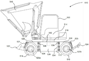
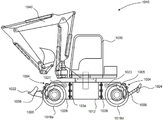
도 4 및 도 5를 참고하면, 본 발명의 실시예에 따른 작업 기계(510)가 다소 간략화된 형태로 도시된다. 본 발명의 구동 장치는 위에서 설명한 것과 실질적으로 동일한 것으로 간주될 수 있으며, 구동 장치는 하부 주행체 조립체(512) 내에 수용된다. 4 and 5, a
선회 링(516)을 통하여 하부 주행체 조립체 상에 상부 구조(514)를 장착하기 위하여 하부 주행체 조립체(512)는 장착 장치(532)를 갖는 메인 섀시(526)를 포함하여 하부 주행체에 관하여 상부 구조의 회전을 가능하게 한다. 다른 실시예에서, 상부 구조의 방향이 하부 주행체(512)에 관하여 고정되도록 장착 장치(532)는 구성될 수 있다. 메인 섀시(526)는 선단과 후단, 그리고 선단과 후단 사이를 연장하는 2개의 측부 플레이트(537)를 포함하며, 여기서 측부 플레이트는 섀시 레일의 부품으로서의 역할을 한다. 선단과 후단 각각은 선단과 후단 상에 보조 섀시(528)를 장착하기 위한 장착 접속부(534)를 갖는다. 장착 접속부(534)는 전면 및 후면의 각 코너에서의 플랜지 상에 (보이지 않는) 3개의 바를 포함하여 볼트(535) 또는 다른 적절한 패스너로 보조 섀시(528)를 메인 섀시(526)에 고정시킨다. 메인 섀시(526)의 측부 플레이트(537)는 (보이지 않는) 적절한 컷 아웃(cut-out)을 갖는 금속 시트로 구성되어 구동 샤프트, 호스 등이 통과하는 것을 허용한다. 다른 실시예에서, 장착 접속부(534)는 메인 섀시(526)에 보조 섀시(528)를 용접하기 적합한 표면을 포함할 수 있다 (아래의 도 6 내지 도 8 참조). The lower
보조 섀시(528)는 선단과 후단 그리고 선단과 후단 사이에서 길이 방향으로 연장하는 2개의 측부 플레이트(518?)를 가지며, 여기서 장착 접속부(534)는 보조 섀시(528)의 선단 또는 후단에 위치한다. 각 보조 섀시(528)의 장착 접속 부는(536) 메인 섀시(526)의 보어(534)에 상보적인 3개의 보어를 갖는 플랜지 형태이다. 다른 실시예에서, 보어의 개수는 필요에 따라 달라질 수 있으며, 그리고 또한 메인 섀시 그리고 보조 섀시의 상단 에지 및/또는 바닥 에지 상에서 가로질러 연장하는 플랜지 상에 제공된다. The
보조 섀시(528)는 장착 접속부(534)에 대해 보조 섀시(528)의 반대 종단에 선회적으로 장착된 스태빌라이저 레그 장치(524) 또는 도저 블레이드 장치(522)를 갖는다. 스태빌라이저 레그 장치(524) 또는 도저 블레이드 장치(522)를 공지된 장치를 각각 이용한 유압 실린더(523, 521)에 의하여 들어올려지거나 또는 낮아질 수 있다. 도저 블레이드 장치(522)는 또한 굴삭시 지면으로부터 인접하는 휠을 들어올림에 의하여 기계를 위한 스태빌라이저의 역할을 수행할 수 있다. The
각 보조 섀시(528)는 지면 결합 구조에 연결되며, 이 실시예에서, 지면 결합 구조는 보조 섀시에 장착된 구동 차축(520a 및 520b) 중 하나 및 각 차축 종단에 회전 가능하게 부착된 휠을 포함한다. 작업 기계(510)의 기능에 맞도록 보조 섀시(528)의 선단과 후단 사이의 길이는 선택될 수 있다. 도 4는 보다 짧은 선회 반경을 필요로 하는 그리고 한정된 공간에서 작업하는 것을 필요로 하는 굴삭기와 같은 작업 기계에 적합한, 상대적으로 짧은 길이 및 짧은 축간 거리를 갖는 작업 기계(510)를 야기하는 2개의 짧은 보조 섀시(528)를 도시한다. 반대로, 도 5는 더 안정적인 하부 주행체를 필요로 하는, 크레인 또는 회전 텔레핸들러와 같은 작업 기계에 보다 적합할 수 있는 긴 축간 거리를 야기하는 2개의 긴 보조 섀시(528')를 갖는 작업 기계(510)를 도시한다. 다른 실시예에서, 긴 보조 섀시와 짭은 보조 섀시의 조합이 이용될 수 있다. Each
도 6, 도 7 및 도 8을 참고하면, 대안적인 메인 섀시(626) 그리고 보조 섀시(728)가 도시된다. 메인 섀시(626) 는 2개의 금속성 측부 플레이트(637, 638) 그리고 상단 에지에서 측부 플레이트에 용접된 상단 플레이트(660)로 구성된다. 상단 플레이트(660)는 상단 플레이트의 중앙에 실질적으로 위치된 선회 링 형태의 장착 장치를 포함한다. 메인 섀시(626)는 상부 코너 주변에서 절곡되고 그리고 측부 플레이트(637, 638)에 용접된 2개의 종단 플레이트(662)를 더 포함한다. 변속기 구성 요소를 위한 대체적으로 사각 공간을 한정하기 위하여 종단 플레이트(662)는 연장되어 상단 플레이트(660)의 에지와 만난다.6, 7, and 8, an alternative
메인 섀시(626)는 종단 플레이트(662)에 의하여 한정된 2개의 장착 접속부(634)를 포함한다. 이 실시예에서, 도 6 및 도 7에 도시된 바와 같이 메인 섀시(626)의 장착 표면에 맞추도록 보조 섀시(728)가 제공될 수 있게 하기 위하여 그리고 그후 그에 용접될 수 있게 하기 위하여 장착 접속부(634)는 구성된다. The
메인 섀시(626)는 기관(도시되지 않음)으로부터의 출력부가 메인 섀시를 통과할 수 있도록 구성된, 측부 표면(637) 중 하나에 도면 부호 642에서 지시된 요부를 갖는다. 기관이 수용된 측부 포드의 보조 요소 또는 구조적 요소의 메인 섀시로의 장착을 위하여 또는 배관 및 케이블이 통과하는 것을 허용하기 위하여 측 표면(638)은 또한 그 표면에 다수의 구멍을 갖는다. The
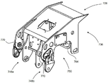
도 7을 참고하면, 보조 섀시(728)는 도면 부호 736에서 대체적으로 지시된 장착 장치를 가지며, 이 장치는 (도 6에 도시된 바와 같은) 메인 섀시(626)에 대응하는 장착 장치(634)에 맞추어지도록 그리고 이 장착 장치에 용접되도록 형상화된다. 7,
보조 섀시는 장착 장치(736)의 반대되는 표면의 가장 낮은 지점에 제공된 2개의 아암 장착 장치(748a 및 748b)를 포함한다. 아암 장착 장치(748a 및 748b) 각각은 한 쌍의 축 방향으로 정렬된 보어 형태이며, 작업 기능을 수행하기 위하여 피봇(700)에 장착된 유압 실린더(도시되지 않음)에 의하여 작동되도록 하기 위하여 이는 스태빌라이저 레그 장치, 도저 블레이드 장치 등이 보조 섀시(728) 상에 선회적으로 장착되는 것을 허용한다.The secondary chassis includes two
보조 섀시(728)는 역전된 U-채널을 한정하는 요부(750)를 가지며, 이 채널은 섀시의 측표면을 통하여 측 방향으로 연장되고 그리고 구동 차축(도시되지 않음)이 섀시에 장착되는 것을 허용하도록 구성된다. 이 실시예에서, 보조 섀시(728)는 보조 섀시의 양 표면 사이에서 연장하는 제 1 장착 프레임(764) 그리고 제 2 장착 프레임(보이지 않음)을 포함한다. 이 실시예에서, 장착 프레임은 보조 섀시(728)의 내부에 용접된다. 구동 차축은 제 1 및 제 2 장착 프레임 사이에서 연장된 피벗 부재(도시되지 않음)를 통하여 보조 섀시(728)에 고정되고, 이 배치는 구동 차축이 제한된 관절 운동을 할 수 있도록 하며, 그로 인하여 지면이 균일하지 않을지라도 휠이 지면 접촉 상태에 유지되도록 한다. The
도 8을 참고하면, 대안적인 보조 섀시(828)가 도시된다. 이 도면의 대응하는 구성 요소는 도면의 대응 구성 요소는 도면의 대응 구성 요소는 도 7에 관하여 100이 더 큰 도면 부호가 붙여지며, 그리고 단지 차이점만이 설명된다. 보조 섀시(828)의 금속 프레임은 도 7에서 설명된 것과 실질적으로 동일하다. 이 실시예에서, 금속 플레이트를 요부(850)를 따라 고정하기 위하여 플레이트(866)는 보조 섀시의 양 측부에 용접된다. 보조 섀시(828)에 관하여 구동 차축을 고정하기 위하여 그리고 관절 운동을 방지하기 위하여, 플레이트(866)는 각 종단에서의 다수의 보어(868)를 포함하여 구동 차축(도시되지 않음)의 부착을 가능하게 한다. 8, an alternative
크레인crane
도 9를 참고하면, 대안적인 작업 기계(910)가 도시되며, 이 실시예에서 작업 기계는 크레인이다. 작업 기계(910)는 도 5의 작업 기계(510)의 하부 주행체 조립체(912)와 유사한, 긴 보조 섀시를 갖는 하부 주행체 조립체(912)를 갖는다. 이 도면의 대응하는 구성 요소는 도면의 대응 구성 요소는 도면의 대응 구성 요소는 도 5에 관하여 접두사 "5" 대신에 접두사 "9"로 도면 부호가 붙여지며, 그리고 단지 차이점만이 설명된다.Referring to Fig. 9, an
상부 구조(914)는 이미 설명된 바와 같이 선회 링(916)을 통하여 하부 주행체(912)에 장착되어 상부 구조 그리고 작업 아암 장치(940)는 하부 주행체에 대하여 회전할 수 있다. The
연결된 상부 구조(914)는 도시된 바와 같이 가장 낮은 위치에서 수평적으로 위치될 수 있는 망원경식 붐(telescopic boom) 형태의 크레인 작업 아암(940)을 갖는다. 본 실시예에서, 호이스트는 케이블(901) 그리고 윈치(902)를 포함하며, 여기서 윈치는 붐의 베이스에 제공된다. 전방과 대조적으로, 붐(940)의 후방에 모터(957) 그리고 윈치(902)를 위치시키는 것은 크레인의 들어올림 용량 그리고 전방 안정성을 향상시킨다. The connected
이러한 실시예에서, 하부 주행체(912)는 하부 주행체에 연결된 4개의 스태빌라이저 레그(924)를 가지며, 그리고 들어올림 작동 동안에 스태빌라이저 레그 는 완전히 연장되어 하부 주행체의 휠(919)를 지면으로부터 들어올린다. In this embodiment, the
스태빌라이저/도저 연결 장치Stabilizer / dozer connection
도 10, 도 11 및 도 12를 참고하면, 대안적인 작업 기계(1010)가 도시된다. 본 실시예의 구동 장치는 위에서 설명된 것과 실질적으로 동일한 것으로 간주될 수 있다. 도면의 대응 구성 요소는 도면의 대응 구성 요소는 도 9에 관하여 100이 더 큰 도면 부호가 붙여지며, 그리고 단지 차이점만이 설명된다. 10, 11 and 12, an
도 10 및 도 11에 도시된 실시예에서, 유압 실린더(1021, 1023) 형태의 선형 액추에이터는 하부 주행체의 적어도 3개의 측부에 의하여 하부 주행체 내에서 밀폐되어 있으며, 여기서 적어도 3개의 측부 중 하나는 실질적으로 공간 위에, 즉 조립된 작업 기계 내의 상부 구조체와 실질적으로 마주보는 하부 주행체의 측부 상에 위치된다. 이는 도 10 내에서 보여질 수 있다. 그러나 액츄에이터를 도시하기 위하여 하부 주행체의 상부 표면은 도 11 및 도 12에서 제거된다. 도시된 실시예에서, 연결 장치(1004)를 통하여 도저 블레이드 장치(1022) 또는 스태빌라이저 레그 장치(1024)를 작동시키기 위하여 유압 실린더는 보조 섀시(1028) 내에 장착되고 그리고 보조 섀시 내의 개구 밖으로 연장된다. 다른 아암에 연결됨에도 불구하고 양 연결 장치(1004)는 실질적으로 동일하다는 것과 문자 L을 형성하는 2개의 아암의 정점에서 보조 섀시(1028)에 선회적으로 장착된, 전체적으로 L형 레버(1005)를 포함한다는 것이 보여질 수 있다. L형 부재의 한 자유단은 유압 실린더(1021, 1023)에 선회적으로 연결되고 그리고 다른 자유단은 링크 아암(1006)의 종단에 선회적으로 연결된다. 링크 아암(1006)의 제 2 종단은 도저 블레이드(1022) 또는 스태빌라이저 레그(1024)에 선회적으로 연결된다. 이 연결 장치는 실린더(1021, 1023)의 일반적인 수평 연장 및 수축을 도저 블레이드 또는 스태빌라이저 레그의 일반적인 아치형 이동으로 효과적으로 전환시킨다. 10 and 11, the linear actuators in the form of
도 12에 도시된 바와 같이, 도저 블레이드 장치(1022)를 장착할 때 다른 선형 연결 장치(1007)가 실질적으로 제공된다. 이 연결 장치(1007)는 L형 레버(1005)의 정점과 동일한 피봇점에서 보조 섀시에 선회적으로 장착된다. 연결 장치(1007)는 링크 아암(1006)과 동일한 선회점에서 도저 블레이드(1022) 또는 스태빌라이저 레그(1024)에 더 선회적으로 연결된다. 이동 동안에 연결 장치(1007)는 도저 블레이드(1022)의 상하 방향을 유지한다. As shown in Fig. 12, another linear connecting
보조 섀시(1028) 내에 유압 실린더를 제공하는 것은 하부 주행체의 전체 치수를 최소화하며 그리고 운전자의 시계를 개선할 수 있다. 더욱이, 이 배치는 유압 실린더에 손상으로부터의 보호를 제공할 것이다. Providing the hydraulic cylinders in the
크레인, 텔레핸들러 또는 굴삭기와 같은 다양한 작업 기계에 걸쳐 실질적으로 동일할 수 있는 메인 섀시를 제공하는 것은 부품의 개수를 줄일 수 있고 그리고 단일 생산 라인이 다수의 기계를 제조하는 것을 허용하며, 그로 인하여 비용이 줄어든다. 위에서 설명된 바와 같이 다수의 조립체로 나누어진다면 보다 많은 섀시를 수송을 위하여 주어진 체적으로 포장하는 것이 가능할 수 있음에 따라 다른 위치에서 제조 및 조립된다면 메인 섀시 및 보조 섀시의 운반을 더 효율적으로 함에 의하여 모듈식 장치는 또한 비용을 절감할 수 있다. Providing a main chassis that can be substantially identical across various work machines such as cranes, telemetry handlers or excavators can reduce the number of parts and allow a single production line to manufacture multiple machines, Is reduced. By dividing into a number of assemblies as described above, it may be possible to package more chassis in a given volume for transport, making it more efficient to transport the main chassis and auxiliary chassis, if manufactured and assembled at different locations, The eating device can also reduce the cost.
구동 차축 장착부를 제외하고 실질적으로 동일할 수 있는 보조 섀시를 제공하는 것은 하부 주행체 구성 요소의 더 낮은 비용 제조를 위하여 대량 생산에 의한 원가 절감이 제공되는 것을 허용할 수 있다.Providing the auxiliary chassis, which may be substantially the same except for the drive axle mount, may allow for cost savings due to mass production for lower cost manufacturing of the lower drive vehicle components.
변형예Variation example
본 발명이 하나 이상의 바람직한 실시예를 참고로 하여 위에서 설명되었을지라도, 청구범위에서 한정된 바와 같이 본 발명의 범위를 벗어나지 않고 다양한 변화 및 변형이 이루어질 수 있다는 것이 인식될 것이다. Although the invention has been described above with reference to one or more preferred embodiments, it will be appreciated that various changes and modifications can be made therein without departing from the scope of the invention as defined in the claims.
본 발명이 특별하게 유리한 것으로 간주된 특정 기계 레이아웃의 문맥에서 설명되었을지라도, 상부 구조 내에 기관 및 유압 펌프를 갖는 일반적인 휠 부착 선회 굴삭기 또는 정역학적 또는 다른 형태의 변속기를 갖는 텔레핸들러, 야지용 크레인 등과 같은 더 일반적인 기계 내에서 본 발명이 사용된다면, 본 발명의 어떤 이점이 달성될 수 있다. 또한, 다른 실시예에서, 원동기는 측부 포드(side pod) 내부 대신에 메인 또는 보조 섀시 내에 위치될 수 있다.Although described in the context of a particular machine layout in which the present invention is considered particularly advantageous, it is to be understood that the invention may be practiced with other types of transmissions, such as a telescopic handler with a mechanical or hydraulic pump in the superstructure, a telescopic handler with a mechanical or other type of transmission, If the present invention is used within the same more general machine, certain advantages of the present invention can be achieved. Also, in other embodiments, the prime mover may be located in the main or auxiliary chassis instead of inside the side pod.
대안적인 실시예에서, 메인 섀시는 블레이드 장치, 스태빌라이저 레그 장치 또는 트랙터형 유압 3-점 연결 장치 중 하나, 차축 그리고 유압 실린더를 위한 장착부를 가질 수 있다. 이 실시예에서, 메인 섀시는 메인 섀시 단지 하나의 보조 조립체를 장착하도록 구성될 수 있다.In an alternative embodiment, the main chassis may have one of a blade device, a stabilizer leg device, or a tractor type hydraulic three-point connection device, an axle, and a mount for the hydraulic cylinder. In this embodiment, the main chassis may be configured to mount only one subassembly of the main chassis.
다른 대안적인 실시예에서, 메인 섀시의 선단 및 후단에 요부를 한정하기 위하여 (예를 들어, 반대의 C-빔 형태의 섀시 레일들을 가짐에 의하여) 메인 섀시는 구성될 수 있다. 조립체가 메인 섀시 내의 요부 내로 삽입될 수 있도록 그리고 메인 섀시에 해제 가능하게 고정될 수 있도록 하기 위하여 부재들은 구성될 수 있다. 이 실시예에서, 서브 조립체는 스태빌라이저 레그 장치, 도저 아암 장치, 3-점 연결 장치 등일 수 있다. 대안적인 실시예에서, 서브 조립체는 또한 메인 섀시에 구동 차축을 장착할 수 있으며, 여기서 도 7 및 도 8에서 설명된 것과 유사한 방식으로 차축은 서브 조립체에 관하여 고정될 수도 또는 고정되지 않을 수 있다. In another alternative embodiment, the main chassis may be configured (e.g., by having chassis rails in opposite C-beam form) to define recesses at the leading and trailing ends of the main chassis. The members may be configured to allow the assembly to be inserted into the recesses in the main chassis and releasably secured to the main chassis. In this embodiment, the subassembly may be a stabilizer leg device, a dozer arm device, a three-point connection device, or the like. In an alternative embodiment, the subassembly can also mount a drive axle to the main chassis, wherein the axle may or may not be fixed with respect to the subassembly in a manner similar to that described in Figures 7 and 8.
다른 실시예에서, 일반적인 기어 박스, 파워시프트 기어박스 및/또는 토크 컨버터 기어박스와 같은 대안적인 변속기 장치가 사용된다. IC 기관, 예를 들어 전기 모터 대신에 또는 IC 기관과 함께 대안적인 원동기가 또한 사용될 수 있다. In alternate embodiments, alternative transmission devices such as general gearboxes, power shift gearboxes, and / or torque converter gearboxes are used. Alternative prime movers may also be used with or instead of IC engines, for example, electric motors, or with IC engines.
작업 기계는 수동 유압 또는 전자-유압 제어부를 이용하여 작동될 수 있다.The work machine may be operated using a manual hydraulic or electronic-hydraulic control.
본 실시예에서, 양 차축 상의 휠들이 조향 가능(즉, 작업 기계는 4륜 조향을 위하여 구성된다)하지만, 대안적인 실시예에서는 차축들 중 어느 하나의 차축 상의 휠만이 조향 가능(즉, 작업 기계는 2륜 조향을 위하여 구성된다)할 수 있다. In the present embodiment, although the wheels on both axles are steerable (i.e., the work machine is configured for four-wheel steering), in alternative embodiments, only wheels on any axle of the axles are steerable Can be configured for two-wheel steering).
Claims (20)
Applications Claiming Priority (2)
| Application Number | Priority Date | Filing Date | Title |
|---|---|---|---|
| GB1419274.4A GB2531765B (en) | 2014-10-29 | 2014-10-29 | An undercarriage for a working machine |
| GB1419274.4 | 2014-10-29 |
Publications (1)
| Publication Number | Publication Date |
|---|---|
| KR20160052391A true KR20160052391A (en) | 2016-05-12 |
Family
ID=52103602
Family Applications (1)
| Application Number | Title | Priority Date | Filing Date |
|---|---|---|---|
| KR1020150151365A KR20160052391A (en) | 2014-10-29 | 2015-10-29 | An Undercarriage for a Working Machine |
Country Status (6)
| Country | Link |
|---|---|
| US (1) | US20160122972A1 (en) |
| EP (1) | EP3015604A1 (en) |
| JP (1) | JP2016089617A (en) |
| KR (1) | KR20160052391A (en) |
| CN (1) | CN105564236A (en) |
| GB (1) | GB2531765B (en) |
Families Citing this family (6)
| Publication number | Priority date | Publication date | Assignee | Title |
|---|---|---|---|---|
| GB2531762A (en) * | 2014-10-29 | 2016-05-04 | Bamford Excavators Ltd | Working machine |
| US20180171792A1 (en) * | 2016-12-19 | 2018-06-21 | Caterpillar Global Mining Europe Gmbh | Machine and Method of Cutting Material |
| US20180179892A1 (en) * | 2016-12-22 | 2018-06-28 | Caterpillar Global Mining Europe Gmbh | Collision Avoidance Control Method and System |
| CA3034670A1 (en) * | 2018-02-27 | 2019-08-27 | Joy Global Surface Mining Inc | Shovel stabilizer appendage |
| USD931343S1 (en) * | 2019-06-26 | 2021-09-21 | J.C. Bamford Excavators Limited | Excavator undercarriage |
| US11459034B2 (en) * | 2021-01-20 | 2022-10-04 | J.C. Bamford Excavators Limited | Undercarriage |
Family Cites Families (51)
| Publication number | Priority date | Publication date | Assignee | Title |
|---|---|---|---|---|
| US2980271A (en) * | 1957-02-11 | 1961-04-18 | Yale & Towne Mfg Co | Lifting mechanism for industrial truck |
| US4077141A (en) * | 1976-09-08 | 1978-03-07 | Caterpillar Tractor Co. | Tire protector assembly for a wheel loader |
| US4151920A (en) * | 1977-07-11 | 1979-05-01 | Caterpillar Tractor Co. | Vehicle main frame |
| US4215874A (en) * | 1978-12-18 | 1980-08-05 | J. I. Case Company | Articulation lock |
| US4220215A (en) * | 1979-07-26 | 1980-09-02 | Caterpillar Tractor Co. | A-frame for carrying loads on a loader |
| US4360311A (en) * | 1979-10-22 | 1982-11-23 | Serge Dufour | Public works machine, such as a hydraulic self-propelled articulated shovel |
| US4318664A (en) * | 1980-05-20 | 1982-03-09 | Pierre Gibert | Self-stabilizing load lifting and handling vehicle |
| US4369989A (en) * | 1980-08-01 | 1983-01-25 | Standard Manufacturing Company, Incorporated | Stabilizing jack for skid steer vehicle |
| FR2488206B1 (en) * | 1980-08-07 | 1985-07-12 | Poclain Sa | CHASSIS CARRIER OF A MOBILE MACHINE AT CENTRAL BATI AND LONGERS |
| US4427334A (en) * | 1982-02-17 | 1984-01-24 | Raygo, Inc. | Load handling apparatus |
| FR2530604B1 (en) * | 1982-07-23 | 1986-06-20 | Gibert Pierre | HANDLING VEHICLE WITH ADJUSTABLE ARM AND INCORPORATED STABILIZER CHASSIS |
| US4512589A (en) * | 1982-12-27 | 1985-04-23 | Cooper Industries Inc. | Oscillating axle override system |
| US4944649A (en) * | 1986-07-21 | 1990-07-31 | Stralow Cecil J | Mechanism for coupling subordinate machine to tractor |
| US4796366A (en) * | 1987-02-27 | 1989-01-10 | Scully Robert M | Plow/scraper assembly for earth mover vehicle |
| US4836740A (en) * | 1987-12-28 | 1989-06-06 | Clark Equipment Company | Pivotal attachment structure |
| US5169278A (en) * | 1990-09-05 | 1992-12-08 | Clark Equipment Company | Vertical lift loader boom |
| US5778569A (en) * | 1995-04-02 | 1998-07-14 | Karl Schaeff Gmbh & Co. | Multi-purpose construction vehicle with at least two subframes and a self-aligning bearing between the subframes |
| JPH09209403A (en) * | 1996-02-02 | 1997-08-12 | Komatsu Zenoah Co | Center frame |
| JP3155700B2 (en) * | 1996-02-08 | 2001-04-16 | 新キャタピラー三菱株式会社 | Tracked vehicles |
| AU726297B2 (en) * | 1996-07-12 | 2000-11-02 | Caterpillar Inc. | Frame assembly for a construction machine |
| US6409459B1 (en) * | 1998-01-30 | 2002-06-25 | Caterpillar Inc. | Linkage assembly for connecting a work implement to a frame of a work machine |
| US6158525A (en) * | 1998-07-10 | 2000-12-12 | Komatsu Ltd. | Main frame structure and steering case of construction equipment |
| IES20000812A2 (en) * | 1999-10-08 | 2001-04-18 | Cornelius William O'flynn | Earth moving apparatus |
| JP3514694B2 (en) * | 2000-03-17 | 2004-03-31 | 株式会社クボタ | Undercarriage structure of turning machine |
| US6616398B2 (en) * | 2000-11-30 | 2003-09-09 | Caterpillar S.A.R.L. | Lift boom assembly |
| US6684537B2 (en) * | 2001-05-28 | 2004-02-03 | Kubota Corporation | Excavator with a piping structure for absorbing variations in hose length |
| US20030066214A1 (en) * | 2001-10-10 | 2003-04-10 | Strong Victor R. | Scraper bowl with cutting edge crowd |
| JP2003276461A (en) * | 2002-01-18 | 2003-09-30 | Kanzaki Kokyukoki Mfg Co Ltd | Working vehicle |
| JP4080974B2 (en) * | 2003-08-12 | 2008-04-23 | 株式会社クボタ | Wheeled work machine |
| US7798738B2 (en) * | 2003-12-18 | 2010-09-21 | Hitachi Construction Machinery Co., Ltd. | Swivel joint for construction machine |
| US7264435B2 (en) * | 2005-05-26 | 2007-09-04 | Caterpillar S.A.R.L. | Lift boom assembly |
| US7740254B2 (en) * | 2005-09-29 | 2010-06-22 | Kubota Corporation | Wheeled work machine |
| JP2007154519A (en) * | 2005-12-06 | 2007-06-21 | Toyota Industries Corp | Working vehicle and skid steering loader |
| EP2368787B1 (en) * | 2005-12-13 | 2014-05-14 | Cody L. Sewell | Compact tool carrier with articulation joint |
| US7854402B1 (en) * | 2007-10-02 | 2010-12-21 | Travis Tonny D | Hydraulic system valving |
| US7736117B2 (en) * | 2007-10-31 | 2010-06-15 | Caterpillar Inc. | Linkage assembly |
| CA2646032C (en) * | 2007-12-13 | 2016-06-21 | Volvo Construction Equipment Holding Sweden Ab | Manual leveling control system and method for construction equipment |
| US8545163B2 (en) * | 2008-06-26 | 2013-10-01 | Kubota Corporation | Loader work machine |
| DE202008013896U1 (en) * | 2008-10-17 | 2010-03-11 | Liebherr-Hydraulikbagger Gmbh | Mobile working device |
| JP5156693B2 (en) * | 2009-06-17 | 2013-03-06 | 日立建機株式会社 | Industrial vehicle engine speed control device |
| NL2004954C2 (en) * | 2010-05-31 | 2011-12-01 | Hudson Bay Holding B V | MOBILE DEVICE. |
| CN103857845B (en) * | 2011-10-07 | 2016-01-20 | 日立建机株式会社 | The soil-discharging device of engineering machinery |
| JP2013117145A (en) * | 2011-12-05 | 2013-06-13 | Hitachi Constr Mach Co Ltd | Wheel type work vehicle |
| WO2014098652A1 (en) * | 2012-12-17 | 2014-06-26 | Volvo Construction Equipment Ab | Front frame arrangement for a working machine and a wheel loader |
| US20140306426A1 (en) * | 2013-04-12 | 2014-10-16 | Caterpillar Inc. | Steering linkage arrangement for articulated mobile machine |
| GB2531762A (en) * | 2014-10-29 | 2016-05-04 | Bamford Excavators Ltd | Working machine |
| GB2531766A (en) * | 2014-10-29 | 2016-05-04 | Bamford Excavators Ltd | Working Machine |
| GB2531763A (en) * | 2014-10-29 | 2016-05-04 | Bamford Excavators Ltd | Working machine |
| GB2531764A (en) * | 2014-10-29 | 2016-05-04 | Bamford Excavators Ltd | Working machine |
| GB2531767A (en) * | 2014-10-29 | 2016-05-04 | Bamford Excavators Ltd | Working Machine |
| GB2531768B (en) * | 2014-10-29 | 2018-01-17 | Bamford Excavators Ltd | An Undercarriage for a Working Machine |
-
2014
- 2014-10-29 GB GB1419274.4A patent/GB2531765B/en active Active
-
2015
- 2015-10-28 JP JP2015211646A patent/JP2016089617A/en active Pending
- 2015-10-29 US US14/927,399 patent/US20160122972A1/en not_active Abandoned
- 2015-10-29 KR KR1020150151365A patent/KR20160052391A/en unknown
- 2015-10-29 CN CN201510717157.0A patent/CN105564236A/en active Pending
- 2015-10-29 EP EP15192196.2A patent/EP3015604A1/en not_active Withdrawn
Also Published As
| Publication number | Publication date |
|---|---|
| GB2531765B (en) | 2017-09-13 |
| JP2016089617A (en) | 2016-05-23 |
| US20160122972A1 (en) | 2016-05-05 |
| CN105564236A (en) | 2016-05-11 |
| GB201419274D0 (en) | 2014-12-10 |
| GB2531765A (en) | 2016-05-04 |
| EP3015604A1 (en) | 2016-05-04 |
Similar Documents
| Publication | Publication Date | Title |
|---|---|---|
| US9828049B2 (en) | Working machine | |
| US11111649B2 (en) | Working machine | |
| US9592733B2 (en) | Working machine | |
| EP3020870B1 (en) | An undercarriage for a working machine | |
| KR20160052391A (en) | An Undercarriage for a Working Machine | |
| JP2016089618A5 (en) | ||
| CN105569107B (en) | Working machine | |
| US20160122971A1 (en) | Working machine | |
| KR102657223B1 (en) | An undercarriage for a working machine |